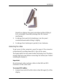
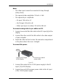
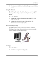
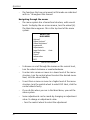
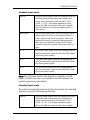
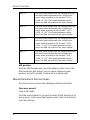
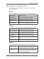
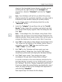
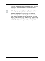
1
Coronis 2MP
Installation & User Manual
(This page intentionally left blank.)
2
Coronis 2MP
Copyright notice
Copyright notice
This document is copyrighted. All rights are reserved. Nor this
document, nor any part of it, may be reproduced or copied in any
form or by any means - graphical, electronic, or mechanical
including photocopying, taping or information storage and
retrieval systems - without written permission of Barco
© 2007 Barco N.V. All rights reserved.
3
Preface
Preface
Notice
Although every attempt has been made to achieve technical
accuracy in this document, we assume no responsibility for errors
that may be found. Our goal is to provide you with the most
accurate and usable documentation possible; if you discover
errors, please let us know.
BarcoView software products are the property of BarcoView.
They are distributed under copyright by Barco N.V. or BarcoView,
LLC., for use only under the specific terms of a software license
agreement between Barco N.V. or BarcoView LLC. and the
licensee. No other use, duplication, or disclosure of a BarcoView
software product, in any form, is authorized.
The specifications of BarcoView products are subject to change
without notice.
FCC notice
This equipment has been tested and found to comply with the
limits of a Class A digital device, pursuant to Part 15 of the FCC
rules. These limits are designed to provide reasonable protection
against harmful interference when the equipment is operated in
a commercial environment. This equipment generates, uses and
can radiate radio frequency energy and, if not installed and used
in accordance with the instruction manual, may cause harmful
interference to radio communications. Operation of this
equipment in a residential area is likely to cause harmful
interference in which case the user will be required to correct the
interference at his own expense.
Canadian notice
This Class A digital apparatus complies with Canadian ICES-003.
Cet appareil numérique de la Classe A est conforme à la norme
NMB-003 du Canada.
4
Preface
Disposal Information
The lamps inside the display contain mercury. Do not throw the
display in the trash. Dispose of it as required by local ordinances
or regulations.
5
Safety Instructions
Safety Instructions
General Recommendations
Read the safety and operating instructions before operating the
display.
Retain safety and operating instructions for future reference.
Adhere to all warnings on the display and in the operating
instructions manual.
Follow all instructions for operation and use.
Electrical shock
Type of protection (electrical):
Class I equipment
Degree of safety (flammable anesthetic mixture):
Equipment not suitable for use in the presence of a flammable
anesthetic mixture with air or with oxygen or nitrous oxide.
Power connection
6
•
Power requirements: The display must be powered using the
12 VDC power supply that is supplied with the display.
•
The 12 VDC power supply must be powered by the AC mains
voltage.
Safety Instructions
•
Power cords:
Power cord with CEE 7 plug: The colors of the mains lead are
colored in accordance with the following code: Green-andyellow: Earth (safety earth), Blue: Neutral, Brown: Line
Power cord with ANSI 73.11 plug: The wires of the power
cord are colored in accordance with the following code:
Green/yellow: ground, White: neutral, Black: line (live)
•
Do not overload wall outlets and extension cords as this may
result in fire or electric shock.
•
Mains lead protection (U.S.: Power cord): Power cords should
be routed so that they are not likely to be walked upon or
pinched by items placed upon or against them, paying
particular attention to cords at plugs and receptacles.
Water and moisture
Never expose the display to rain or moisture.
Never use the display near water - e.g. near a bathtub,
washbasin, swimming pool, kitchen sink, laundry tub or in a wet
basement.
Ventilation
Do not cover or block the ventilation openings in the cover of the
set. When installing the display in a cupboard or another closed
location, heed the necessary space between the set and the
sides of the cupboard.
Installation
Place the display on a flat, solid and stable surface that can bear
the weight of at least 3 displays. If you use an unstable cart or
stand, the display may fall, causing serious injury to a child or
adult, and serious damage to the equipment.
More warnings in the Installation chapter.
7
Safety Instructions
This apparatus conforms to:
CE, IEC 60950, UL 60950, CAN/CSA C22.2 No. 60950 (c-UL), CCC.
National Scandinavian Deviations for Cl. 1.7.2 :
Finland: "Laite on liitettävä suojamaadoituskoskettimilla
varustettuun pistorasiaan"
Norway: "Apparatet må tilkoples jordet stikkontakt"
Sweden: "Apparaten skall anslutas till jordat uttag"
Operating precautions
Continuous operation of the display with the same screen may
result in some image sticking on the LCD panel.
Over 10 hours operation with the same image content is not
recommended.
Switching on the display DPMS may decrease the risk of image
sticking (image retention).
8
Copyright notice................................................................................... 3
Preface ................................................................................................. 4
Safety Instructions............................................................................... 6
Display Controller Installation .................................................. 13
BarcoMed CORONIS display controller overview ................................ 15
BarcoMed CORONIS display controller installation ............................. 17
Display Installation ................................................................... 21
Overview............................................................................................ 23
Introduction ................................................................................ 23
Package contents ....................................................................... 25
Controls and connectors............................................................. 26
Installation ......................................................................................... 29
Precautions ................................................................................. 29
Before installing the display...................................................... 29
Portrait or landscape position.................................................... 30
Connecting the cables................................................................ 31
Routing the signal cables .......................................................... 34
Using the USB hub...................................................................... 35
Tilt and swivel positioning......................................................... 35
Starting up .................................................................................. 35
How to avoid image retention ......................................................... 37
Software Installation ................................................................ 39
Installing the BARCOMED display controller drivers and software..
41
Display Controller Tools ............................................................ 47
BarcoMed control panel settings ...................................................... 51
Accessing the Barco tab ............................................................. 51
Advanced Properties .................................................................. 53
Device details ............................................................................. 56
9
Display Operation ..................................................................... 57
Operation ........................................................................................... 59
Switching to stand-by position.................................................. 59
Controlling the display ............................................................... 59
Using the Autoset* functions..................................................... 62
Controlling Video Contrast* and Video Brightness*.................. 64
Setting the Luminance value..................................................... 66
Making adjustments .................................................................. 67
Selecting inputs.......................................................................... 69
Settings ....................................................................................... 70
Preset* ........................................................................................ 72
Getting information.................................................................... 73
Advanced functions ........................................................................... 75
About this chapter...................................................................... 75
Advanced functions in the Adjustments menu ........................ 76
Advanced functions in the Settings menu................................ 77
Advanced functions in the Preset menu................................... 80
Advanced functions in the Information menu.......................... 81
Maintenance ...................................................................................... 83
Troubleshooting ................................................................................. 85
Windows does not show the desired display settings............. 85
Pixel Faults.................................................................................. 86
Technical specifications ..................................................................... 87
GEOMETRY ................................................................................... 87
VISUAL PERFORMANCE................................................................ 87
INPUTS......................................................................................... 88
SCANNING SYSTEM...................................................................... 88
CONTROLS.................................................................................... 89
POWER SUPPLY............................................................................ 89
Dimensions (W x H x D)............................................................. 89
10
Net weight.................................................................................. 89
Operating Temperature.............................................................. 89
Storage Temperature.................................................................. 89
MediCal Software
Installation and Operation................................................... 91
MediCal Pro installation and operation ............................................ 93
MediCal Pro software installation ............................................. 93
Using MediCal Pro ...................................................................... 93
Troubleshooting........................................................................ 95
11
12
Display Controller Installation
13
Display Controller Installation
(This page intentionally left blank.)
14
BarcoMed CORONIS display controller overview
BarcoMed CORONIS display controller overview
The BarcoMed CORONIS display controller delivers a quality image
with 1024 simultaneous shades of gray for medical viewing
applications.
Minimum system requirements
•
Pentium II 266 MHz with 128 MB RAM (Pentium II 800MHz
with 256 MB RAM for cineloops)
Important: Other hardware and software installed in the
system may require more system memory for best
performance.
•
64-bit/66Mhz PCI slot with no obstructions
•
PCI 2.2 Compliant
•
Windows® XP Professional Service Pack 1, Windows® 2000
Professional Service Pack 4 or Windows NT® 4.0 Service
Pack 6
Features of the BarcoMed CORONIS display controller
•
Dual Head Configuration
•
64MB Video Memory
•
10-bit performance on LCD
•
1024 Simultaneous shades of gray
•
10-bit in/10-bit out LUT
•
Portrait or Landscape Mode
•
Hardware cursor
•
64-bit/66MHz Single slot PCI card
•
Displays VGA boot messages on CORONIS 2MP displays.
15
BarcoMed CORONIS display controller overview
Supported resolutions for each head of the BarcoMed CORONIS display
controller
For Coronis 3MP Displays
• 1536 x 2048 @ 60 HZ (primary)
• 2048 x 1536 @ 60 Hz
For all BarcoMed CORONIS display controllers
The following resolution is also available when the OS is
booted in VGA mode.
• 640x480 @ Default Refresh Rate, 16 colors
System Configuration Guidelines
Because of the low power consumption and low heat generation
of the BarcoMed CORONIS display controller, multiple controllers
may be installed in adjacent PCI slots or adjacent to other PCI
boards. Additionally there should be no need to modify either
the PC’s power supply and/or cooling system.
16
BarcoMed CORONIS display controller installation
BarcoMed CORONIS display controller installation
Caution: Wear a grounded, protective ESD strap during
installation or handling of the display controller. Electrostatic
charges can damage the display controller.
Prior to installing your BarcoMed CORONIS display controller(s) in
your PC please take a few minutes to familiarize yourself with
both the display controller and the PCI slots in your computer.
Figure 1: The BarcoMed CORONIS display controller
Jumper location
There is one user changeable jumper on the BarcoMed CORONIS.
It is used to enable or disable the VGA capabilities of the display
controller.
17
BarcoMed CORONIS display controller installation
Figure 2: VGA Jumper Enlarged View
Using the VGA capabilities of the BarcoMed CORONIS
Prior to installing the BarcoMed CORONIS, decide if you are going
to use its on-board VGA capabilities. If you are, check the setting
of the Jumper at J-1 on the display controller (see figure 2 VGA
Jumper Enlarged View). By default, VGA should be enabled, on
the top two pins.
NOTE: To use multiple BarcoMed CORONIS display controllers in a
single host with VGA enabled, you need to enable VGA on only
ONE of the BarcoMed CORONIS display controllers and disable VGA
on ALL other BarcoMed display controllers.
Examples of PCI slots
Although the BarcoMed CORONIS controller is a 64-bit board, it
may be installed in either a 64-bit or 32-bit PCI slot. However,
installing it in a 32-bit PCI slot will result in a decrease in
performance. Figure Figure 3 illustrates the types of slots so that
you can correctly identify which one to use for the
BarcoMed CORONIS.
18
BarcoMed CORONIS display controller installation
Figure 3: PCI and RAID Controller Slots
Install the BarcoMed CORONIS controller in your computer
following these steps:
1.
Turn off the power to your computer and disconnect the
power cord, however make sure that the computer chassis is
still grounded.
2.
Remove the chassis cover according to the manufacturer’s
instructions. Be sure to observe safety warnings.
3.
If you have decided to use the on-board VGA capabilities of
the BarcoMed CORONIS (see Using the VGA capabilities of
the BarcoMed CORONIS on page 18), you must now remove
any VGA display controller(s) that are currently installed in
the computer or disable any VGA controllers that are
integrated into your PC’s motherboard.
4.
Install the BarcoMed CORONIS Controller into a free PCI slot,
either 64-bit or 32-bit (see figure 3, for examples of slots).
Be sure that the display controller is seated firmly in the slot.
5.
Secure the card to the chassis with the PC’s I/O panel
mounting screw, and replace the chassis cover.
6.
Connect the primary display (left most display in a linear
configuration, top most in a vertical configuration) to the
uppermost connector on the BarcoMed CORONIS (the output
farthest from the motherboard – “Head 1” in figure 4
19
BarcoMed CORONIS display controller installation
below) using the provided DVI cable. For a dual-headed
BarcoMed CORONIS setup, connect the secondary display to
the other connector on the display controller.
7.
Replace the chassis cover, reconnect the power cord, turn on
the power, and boot the system as usual.
Running multiple BarcoMed CORONIS display controllers in a single host
The physical order of the displays may vary when you are
running multiple BarcoMed CORONIS display controllers. This is
due to the PC’s PCI bus control in the system BIOS, and not the
BarcoMed display controller. It may become necessary,
depending on how your PC’s BIOS configures the PCI bus, to
switch your DVI display connections to achieve a linear desktop
configuration.
Figure 4: The Video Outputs.
20
Display Installation
21
Display Installation
(This page intentionally left blank.)
22
Overview
Overview
Introduction
The MFGD 2320, BARCO’s 20” 2 megapixel grayscale LCD display,
guarantees perfect image quality in medical imaging
applications.
The display combines a TFT (thin film transistor) liquid crystal
display panel structure and a built-in backlight with inverter for a
better picture quality. It is designed to meet the users’ needs for
performance, consistency, and outstanding image quality
through a streamlined development process.
If the Portrait Accelerator option is installed, the display can be
used in portrait or landscape version, simply by turning the
panel. The tilt & swivel foot allows ideal positioning of the panel,
in height and viewing angle.
The panel can be adjusted by means of a control wheel on the
display.
I-Guard
I-GUARD® is Barco’s patent-pending, built-in calibration device,
continuously maintaining image quality. With I-GUARD®, QA
checks no longer need to disturb normal radiology activities, as
they can be performed while applications are running.
I-GUARD® allows radiologists or QA administrators to calibrate
their viewing stations or adjust the panel’s curve to DICOM
standards without administrator intervention.
Autoset feature
The display has an Autoset feature that helps the user to adjust
standard presets: With one single function, you can automatically
adjust the display completely.
23
Overview
Autoscan
When you connect a video signal, the display checks in the
internal memory if the signal has been adjusted before. If so, it
selects the settings and parameters that match the connected
signal.
When you connect a video signal that hasn’t been connected
before, and adjust the display to the signal, the adjustments and
signal timing parameters are stored in a programmable preset.
Best resolution
The optimum and recommended resolution is 1600 x 1200 or
1200 x 1600 (if the Portrait Accelerator option is installed).
The recommended refresh rate is 60 Hz.
Would you have trouble selecting a proper display setting in
Windows, please refer to the Troubleshooting section further.
BARCO’s BarcoMed Coronis imaging board is the best choice to
drive the MFGD 2320 display.
Power saving (DPMS)
The MFGD 2320 is equipped with a power saving system.
When left idle for a certain time, the computer connected to the
display, will power down the display. The power saving system
can be switched on or off using the on-screen menus.
This system requires a computer imaging board that supports
power saving management.
Ambient Light Compensation (ALC)
When enabled, the ALC system automatically adapts the display
light output, depending on the ambient light in the room. The
ambient light is measured by the ALC optical sensor located at
the front of the display.
24
Overview
Package contents
The package should include the following items, please check. If
some of the items are missing, please contact the reseller from
whom you have purchased the unit.
•
The MFGD 2320 display
•
Power supply
•
DVI cable
•
Analog video cable
•
USB cable
•
Two velcro strips to bind the cables
•
European power cord
•
American power cord
•
This user manual
If the display is part of a Coronis system, the package contains
more items. Please refer to the packing list on the outside of the
Coronis box.
25
Overview
Controls and connectors
1
2
Figure 5
Front
(1) Ambient Light Compensation (ALC) sensor
(2) Power LED
26
•
The LED is off when the display is off.
•
The LED is green when the display is on (when enabled in
the on-screen menus).
•
The LED is orange when the display is in Stand-by powersaving mode.
Overview
4
3
Figure 6
Side
(3) USB downstream connector
(4) Control wheel for navigating through the on-screen display
(OSD) menus and changing values in the menus
DVI
5
D15
6
VS
7
CS/HS
8
VIDEO
9
10
11
12
Figure 7
Rear
(5) Digital DVI (video and data) input
(6) D15 (VGA) video connector
(7) Vertical sync input
(8) Composite / Horizontal sync input
27
Overview
(9) Composite video input
(10) USB downstream connector
(11) USB upstream connector
(12) DC 12V power input
28
Installation
Installation
Precautions
•
Keep your original packaging. It is designed for this display
and is the ideal protection during transport.
•
Avoid reflections in the flat panel to reduce eye strain.
•
Place the display on a strong and stable table or desk.
•
Keep the display away from heat sources and provide
enough ventilation in case it is built in a rack or console.
•
Make sure all equipment is switched off before connecting
the signals.
Before installing the display
Important:
In the factory, the height-positioning system in the display foot is
blocked with a clip to prevent damage during transportation.
Before installing the display, you must remove this clip.
Clip
Figure 8
29
Installation
To remove the clip:
1.
Position the display with its rear side facing you.
2.
Lift up the 2 clips of the foot cover to release the cover from
the foot.
3.
Pull the lower side of the cover towards you and
simultaneously slide the cover downward.
4.
Pull the red clip out of the fixation holes in the foot.
You can better leave the cover off the foot while connecting the
signal cables to the display.
Portrait or landscape position
You can change the orientation of the panel at any time, but it is
more convenient to select landscape or portrait orientation
before connecting the cables.
To change the panel orientation:
30
1.
Stand at the front side of the panel and take the panel at
both sides.
2.
Very important: Tilt the panel before changing the
orientation.
Installation
Figure 9
Should you change the panel orientation without tilting it
first, you might irreversibly damage the tilt & swivel
mechanism.
3.
To change from portrait to landscape, turn the panel
counterclockwise while tilting it slightly.
4.
To change from landscape to portrait, turn clockwise.
Connecting the cables
To get access to the connectors, open the cover of the connector
compartment by pulling down the 2 clips of the cover.
The signal cables can be routed inside the display foot. Therefore,
remove the foot cover before connecting the cables (see "Before
installing the display").
Important:
Do not connect video and sync cables to the BNC and D15
connectors at the same time.
To connect DVI cables:
1.
Connect one end of the DVI cable to the DVI input (5) of the
display.
31
Installation
2.
Connect the other end of the DVI cable to the video output of
your DVI signal source.
3.
Route the cable so that it enters the connector compartment
at the place where the cover is bulged.
To connect analog video & sync cables on BNC:
Connect the video & sync output of the signal source to the video
and sync inputs (9), (8) and (7) of the display.
The inputs accept the following signals:
•
Video with separate horizontal and vertical sync.
• The connection consists of 3 cables.
• Connect the video cable to the connector Video (9).
• Connect the horizontal sync cable to the connector HS/CS
(8).
• Connect the vertical sync cable to the connector VS (7).
• Make sure the signal connected to the HS/CS connector
does not contain Composite sync.
•
Video with external composite sync.
• The connection consists of 2 cables.
• Connect the video cable to the connector Video (9).
• Connect the composite sync cable to the connector HS/CS
(8).
• Make sure no signal is connected to the VS connector.
•
Video with internal composite sync (sync on video).
• The connection consists of 1 cable.
• Connect the video (with sync) cable to the connector Video
(9).
32
Installation
Notes:
•
The video inputs cannot be connected in loop-through
(daisy-chain).
•
The required video amplitude: 700 mV ± 3 dB.
•
The required sync. amplitude:
• VS input: 700 mV to 4 V
• HS/CS input: 500 mV to 4V
• Video input (sync on video): 150 mV to 600 mV
To connect analog video & sync cables on D15:
1.
Connect one end of the VGA cable to the D15 input (6) of the
display.
2.
Connect the other end of the VGA cable to the video output
of your computer.
3.
Route the cable so that it enters the connector compartment
at the place where the cover is bulged.
To connect the power:
Connect to DC input
of the display
Connect one end of
power cable
Figure 10
1.
Connect the output of the 12V DC power supply to the DC
input (12) of the display.
2.
Connect one end of the proper power cable to the AC input
of the 12V DC power supply.
33
Installation
3.
Connect the other end of the power cord to a grounded
power outlet.
4.
Route the cable so that it enters the connector compartment
at the place where the cover is bulged.
Routing the signal cables
After connecting all cables, fix them in the cable tie at the rear of
the connector compartment. Bind the cables together above and
under the foot, by means of the 2 velcro strips included in the
package.
After fixing the cables, put the connector compartment cover
back in place. Pay attention that the signal cables are positioned
under the bulge in the cover.
Next, fix the cables in the plastic clamps on the foot. At last, put
the foot cover back in place.
To put the foot cover in place:
Connector
compartment
Push the upper side
of the cover onto
Signal cables routed under foot
cover
Figure 11
34
1.
Push the upper side of the cover onto the foot, so that the
hooks on the cover are positioned right under the holes in
the foot.
2.
Slide the cover upward while moving the lower side of the
cover towards the foot.
Installation
3.
Press the cover to the foot so that both clips make a clicking
sound.
Using the USB hub
The USB interface inside the display allows you to connect USB
devices, such as a keyboard, mouse or digital camera, to the
display.
To use the USB hub:
1.
Connect the display’s USB upstream connector (11) to the
USB port of the PC.
2.
Connect any USB device to any of the display’s USB
downstream connectors (3) or (10).
Tilt and swivel positioning
Adjust the position of the panel for best viewing conditions.
The display foot allows adjusting the horizontal viewing angle,
vertical viewing angle and panel height.
Figure 12
Starting up
Proceed as follows:
1.
Switch on the signal source (E.g., PC).
35
Installation
2.
36
If necessary, select a suitable resolution or signal format for
the signal source.
How to avoid image retention
How to avoid image retention
Image retention (image sticking, ghost image) is the phenomenon
where an image, or a part of it, seems to be ‘burnt’ in the LCD panel.
When you display e.g. a uniform light gray image you distinguish the
ghost image in the background.
This phenomenon occurs on all types of LCD panels when a static image
remains on the screen for a long time (unfortunately the exact period is
not predictable). Also parts of the image that do not change often (e.g.,
toolbars, buttons, borders) are susceptible to image retention.
Image retention may be undone in some cases, but it may also damage
the LCD panel permanently. So it is better to take precautions during
product installation to avoid it.
Here are some countermeasures you can take:
Power off, power save mode, screen saver
Very important is to use screen savers and power saving modes as
much as possible. If you do not need the display for a few hours, switch
it off. If you only need to look at it when you actually do something on
the screen, use a screen saver.
The amount of “relaxation” time should be considerable, the more you
do it the better. “Flashing” the screen for a few seconds with a screen
saver is not sufficient. Image retention is a slow process to build up, but
it also disappears slowly.
Re-Layout
In most applications, a display is used to show a layout of several
components with borders. Whereas the content in these windows can
change continuously, the borders are static images and may cause
boundary image retention. The layout of the windows (size, number of
windows, etc.) should be changed as much as possible.
37
How to avoid image retention
To activate appropriate screen saving, proceed as follows:
1. In the display OSD menus, open the Settings menu and switch
DPMS on. For more information, please consult the display
operation chapter.
2. In Windows, open the Display control panel. Open the Screen
Saver tab.
3. Select a screen saver from the Screen saver drop-down box.
4. Set the Wait time to 10 minutes.
5. Click the button Power... The Power Options Properties dialog
opens.
6. In the Turn off monitor drop-down box, select After 20 mins.
7. Click Apply.
8. Close the control panel.
38
Software Installation
39
Software Installation
(This page intentionally left blank.)
40
Installing the BARCOMED display controller drivers and software
Note: The installation dialog will display in English if your
operating system’s language is not supported.
This process applies to the following versions of Windows:
•
•
•
•
•
Windows 2000 Professional,
Windows XP Professional,
Windows Professional x64 Edition,
Windows Server 2003, and
Windows Server 2003 x64 Edition.
You will need to install the BARCO MEDICAL IMAGING DISPLAY SYSTEM
drivers and software in the following cases:
1.
• After you have installed the display controller(s) for your
BARCO MEDICAL IMAGING DISPLAY SYSTEM in your system for the
first time.
• After you have reinstalled or upgraded your operating
system.
Start your system. When the Found New Hardware Wizard
comes up, click Cancel. When the System Settings Change
window asks you to restart your computer, click No.
Note: Both displays connected to a single display controller
must have the same physical orientation and resolution in
order to be attached to the Windows desktop.
2.
Run the Barco Product Installation Wizard.
The Barco Product Installation Wizard should start
automatically when you insert the Barco System CD-ROM
into your CD drive after the operating system has started. If
your CD drive’s auto-run is not enabled or the Barco Product
Installation Wizard does not start automatically, you can run
the Barco Product Installation Wizard manually by following
these steps:
a) Click the Start button in the task bar.
b) Click Run.
41
Single Source Master
c)
Click Browse and browse to the root directory of the
BARCO MEDICAL IMAGING DISPLAY SYSTEM CD-ROM and click
on the file, Setup.exe, and click Open.
d) Click OK.
or
a) Browse to the root directory of the BARCO MEDICAL
IMAGING DISPLAY SYSTEM CD-ROM and double click on the
file, Setup.exe.
3.
Click Next on the Welcome page.
4.
Click Next on the Components to be installed page.
5.
Follow the wizard’s on-screen instructions to complete the
installation.
Note: When the page shown in figure 1 appears you may
either click Next to accept the default settings or if you know
the settings required for your viewing application, you may
select them now and then click Next. You may change these
settings later by using the Barco pages of the Windows
Display Control Panel.
Figure 1
42
Please refer to your application manuals for information on
the correct Palette and Drawing modes to select.
6.
When the driver setup is complete, click the Finish button.
The Barco Product Installation Wizard will now guide you
through the installation of MediCal QAWeb, MediCal Pro, or
NioWatch, BarcoMed SelfExam, and the Barco on-line
documentation.
7.
When the Setup complete message appears, select Reboot
System Now and click Finish.
Automated display configuration
Once the drivers, software and documentation have been
installed and your system has been rebooted, the Barco Monitor
Plug and Play Software should automatically detect your Barco
displays and attach them to the desktop with the correct
resolution. If the Barco Monitor Plug and Play Software fails to
detect your Barco displays or fails to attach them to the desktop
correctly please refer to the section, Setting the resolution of
your CORONIS 2MP display on page 97 in the Troubleshooting
section of this manual.
Reinstalling drivers
You can install new drivers or reinstall existing drivers at any
time by using the Barco Set-up wizard on your Barco system CDROM, see Installing the BARCOMED display controller drivers
and software on page 41 of this manual.
Uninstalling the drivers and software
To un-install the BARCO MEDICAL IMAGING DISPLAY SYSTEM drivers,
software or documentation, please use the Windows Add/
Remove Programs utility. This can be found in the Windows
Control Panel.
Note: If you installed your BARCO MEDICAL IMAGING DISPLAY SYSTEM
drivers with DualView enabled, the wizard may warn you that
DualView must be disabled before the drivers can be
43
Single Source Master
un-installed. This is normal, please follow the prompts from the
wizard.
Command line (Silent) Install of Drivers and Software
Specifying the silent install option causes most of the GUI
associated with the installer to disappear. A background progress
window will still be visible, but no user input will be required.
The silent install behavior is dictated by the SETUP.INI file. Each
application is allowed to have separate command-line
parameters for normal and silent installs.
To install the drivers and software silently, please follow the
steps below:
1.
Insert the BARCO MEDICAL IMAGING DISPLAY SYSTEM CD-ROM into
your CD/DVD drive. When the Barco Product Installation
Wizard starts click “Cancel”.
2.
Click the Start button in the task bar.
3.
Click Run.
4.
Click Browse and
a) browse to the root directory of the BARCO MEDICAL
IMAGING DISPLAY SYSTEM CD-ROM.
b) Click on the file, Setup.exe, and click Open.
or
a) Browse to the root directory of the location where you
saved the contents of your BARCO MEDICAL IMAGING DISPLAY
SYSTEM CD-ROM.
b) Click on the file, Setup.exe, and click Open.
5.
In the Open address window, place your cursor at the end of
the line of text that appears and add the following text after
Setup.exe, a space and -silent. Click OK.
Example (where D is the name of your CD/DVD drive):
D:\Setup.exe -silent
44
See figure 2 for an example of how the command line
window should look when using the silent install from the
BARCO MEDICAL IMAGING DISPLAY SYSTEM CD-ROM.
Figure 2
45
Single Source Master
46
Display Controller Tools
47
Display Controller Tools
(This page intentionally left blank.)
48
BarcoMed Control Panel Settings
49
Single Source Master
(This page intentionally left blank.)
50
BarcoMed control panel settings
This chapter describes how to configure the displays in your
Barco Medical Imaging Display System using the tools available
through the Advanced button on the Settings tab of the Windows
Display Control Panel.
Accessing the Barco tab
Note: You must have logged on to Windows using an account
with administrator privileges in order to use the Barco portions of
the “Windows Display Control Panel” to change any display
settings.
1.
Open the “Windows Display Control Panel” by one of the two
methods below:
a) Start > Settings > Control Panel > Display
or
b) Open the “Display Properties Control Panel” by right
clicking in an empty area on the desktop, then select
“Properties”.
2.
Click on the “Settings” tab.
3.
Select the “rectangle” that represents the Barco display
whose settings you wish to change.
4.
Click on the “Advanced” button.
5.
Select the “Barco” tab from the Properties screen.
Using the Barco tab
The Barco tab is divided into three sections. The first section
provides information about the graphics controller and allows
access to the graphics controller advanced configuration pages.
The second section provides information about the display. The
bottom section allows access to two Barco tools, Barco System
Report and Barco’s softcopy QA solution, MediCal QAWeb,
MediCal Pro or Niowatch, depending on which solution is
51
BarcoMed control panel settings
Single Source Master
installed on your system. Also, there is a active link to the Barco
Medical Imaging web site.
Figure 1 Barco Tab
Barco System Report
The Barco System Report, also known as BarcoMed SelfExam, is a
wizard based tool which collects data about the components that
are installed in your system. This information is used by the
Barco MID Support team when trying to resolve customer issues.
MediCal QAWeb/MediCal Pro/NioWatch
Clicking on the MediCal QAWeb/MediCal/NioWatch Pro button
will launch the softcopy QA application that is installed on your
system. Please refer to the MediCal QAWeb, MediCal Pro, or
NioWatch manual for information about this application.
52
Advanced Properties
To access the advanced properties configuration pages for your
Barco display controller(s), click on the Advanced button in the
Graphics Device Information section.
BarcoMed advanced configuration
There are two pages accessible from the advanced configuration
button. They are:
• Barco Drawing Modes
• Device Details
These two pages replace the following three pages found in
earlier versions of the BarcoMed display controller drivers.
• the BarcoMed Driver Tab,
• the BarcoMed Hardware Tab, and
• the BarcoMed Display Tab.
Barco Drawing Modes
The Barco Drawing Modes page of the Advanced Properties page
is divided into four sections: Palette Mode, Drawing Modes,
Monitor Configuration, Graphics Board.
Palette Mode
In the Palette Mode section you can choose one of the four
following Palette Modes. If you are using a color display in
conjunction with your Barco grayscale display(s), prior to
selecting a palette mode please make certain that you have
configured your Windows desktop correctly. (See the section
“Setting the resolution of your Coronis 2MP display”.)
Color to Gray Compatibility
Use this palette option for applications, such as Java, which
require True Color support. Such applications may not work
correctly when using one of Barco's three “Standard 8-bit (256color)” palette modes. All applications that are designed to work
53
BarcoMed control panel settings
Single Source Master
correctly with 8-bit (256-color) modes should continue to work
normally.
Note: Ditherng is not used while in this mode. Also, direct access
to the hardware through DirectDraw is not allowed in this mode.
User Modifiable Color Palette
This option allows applications to modify the palette contents
dynamically. This mode reserves the first 10 and last 10 entries
in the palette for the Windows operating system, but
applications can manipulate the middle 236 entries. This is the
standard palette mode as configured by Windows.
Static Gray Palette including standard system colors
This option sets the palette to be a static linear set of 236 gray
values. The 20 standard system colors are converted from RGB to
gray values and are added to the 236 static gray values.
Applications are denied the ability to dynamically change or
allocate palette entries.
Static Gray Palette with NO system colors
This option sets the palette to be a static linear ramp of 256
shades of gray. Applications are denied the ability to dynamically
change or allocate palette entries.
Drawing Modes
In the Drawing Mode section you can choose from the following
Drawing Modes. If any of the options in this section are grayed
out, then they are not available for the model controller with
which you are working.
Enable DirectDraw
This option allows the user to enable or disable DirectDraw.
DirectDraw is a software interface that provides direct access to
display devices while maintaining compatibility with the
54
Windows graphics device interface (GDI). DirectDraw is enabled
by default.
More information about DirectDraw is available through the online help.
Enable Dithering
This option allows the user to enable or disable dithering.
Dithering is a technique for increasing the perceived range of
colors in an image at the cost of spatial resolution.
Note: This option is only available when the User Modifiable
Palette mode is selected. If either the Static Gray Palette
including Standard System Colors mode or the Static Gray
Palette with NO System colors mode is selected, the “Enable
Dithering” check box will be grayed-out, and dithering will be
automatically disabled.
More information about Dithering is available through the online help.
Disable 10-bit grayscale
Use this option for standard Windows®-based applications that
require 8-bit color support (256 colors), such as Internet Explorer,
Excel, etc.
Do not use this option for applications that require 10-bit pixel
support (1024 simultaneous shades of gray) and use extended
depth graphic libraries such as WinBarco.
Description of 10-bit grayscale
To show 1024 simultaneous shades of gray all BarcoMed “H”
series display controllers, such as the BarcoMed 5MP2FH or
BarcoMed Coronis or example, run in extended depth (10-bit)
mode by default.
Implications
When turned on the “Disable 10-bit grayscale” option causes a
BarcoMed Coronis display controller to run in 8-bit mode, which
55
BarcoMed control panel settings
Single Source Master
results in increased performance since the frame buffer is set to
run with 8-bit pixels. While this option may be used with
applications that normally require 10-bit support, there will be a
loss of pixel depth, i.e. 256 shades of gray instead of 1024
simultaneous shades of gray.
Disable RGB To Static Gray Color Translation
Select Disable RGB To Static Gray Color Translation if you wish to
have RGB values equally weighted, with 1/3 each. When not
selected, then the International Commission on Illumination (CIE
– Commission Internationale de I’Eclairage) model will be
adapted, which weights the colors as 59% Green, 30% Red, 11%
Blue.
Monitor Configuration
If the options in this section are grayed out, then they are not
available for the model controller with which you are working.
Graphics Board
There is one option in this section, the Update Firmware button.
Clicking this button will launch the BarcoMed Hardware
Configuration utility. This program allows the user to flash
update the firmware stored in the ROM of the currently selected
BarcoMed display controller. The BarcoMed Hardware
Configuration utility is implemented in a Wizard format, which
guides the user through the flash update procedure. The user will
be prompted to select a firmware update file to use for the
update process. This file will be provided by Barco Medical
Imaging if and when a firmware update is required.
Device details
The Device Details page provides detailed information about the
display controller connected to the active display. This
information is useful in debugging issues that may occur when
using your Barco Medical Imaging Display System.
56
Display Operation
57
Display Operation
(This page intentionally left blank.)
58
Operation
Operation
Operating precautions
Continuous operation of the display with the same screen may
result in some image sticking on the LCD panel.
Over 10 hours operation with the same image content is not
recommended.
Switching on the display DPMS may decrease the risk of image
sticking (image retention).
Switching to stand-by position
When the display is on and no on-screen menus are visible, press
the control wheel (4) for a few seconds to switch the display in
stand-by.
When the display is in stand-by, press or turn the control wheel
to switch it back on.
Controlling the display
The control wheel (4) at the bottom (landscape orientation) or at
the side (portrait orientation) allows you to perform controls.
The control wheel is a rotation - click system. It provides the
following functions:
•
Short click: Enter menus, confirm selections, and toggle
between different options
•
Rotate: Browse through menus, increase or decrease
adjustment values
About the on-screen menus
•
The content of the on-screen menus depends on the
selected video input: Some of the functions are present in
the analog modes (BNC and DB15) but are not present in DVI
mode.
59
Operation
•
The functions that are not present in DVI mode are indicated
with an * throughout this manual.
Navigating through the menus
•
The menu system has a hierarchical structure, with several
levels. To display the on-screen menus, turn the wheel (4).
The Main Menu appears. This is the top level of the menu
system.
MFGD 2320
MAIN MENU
Autoset*
Video Contrast*
Video Brightness*
Luminance
Adjustments
Input Selection
Auto
Settings
Preset*
Information
EXIT
* Not in DVI mode
•
To browse or scroll through the menus on the current level,
turn the wheel clockwise or counterclockwise.
•
To enter into a menu or move to a lower level of the menu
structure, turn the control wheel to select the desired menu.
Next, click the wheel shortly.
•
To exit from a menu or move to a higher level of the menu
structure, turn the control wheel to select EXIT. Next, click the
control wheel shortly.
•
If you do this when you are in the Main Menu, you exit the
menu system.
•
Some adjustments can be made by changing an adjustment
value. To change an adjustment value:
• Turn the control wheel to select the adjustment
60
Operation
• Click the wheel shortly. The adjustment name appears, as
well as the current adjustment value
• Turn the wheel to change the value
• Click the wheel shortly to confirm the change and return to
the menu
•
Some adjustments can be made by selecting from a range of
predefined settings. To change the selection:
• Turn the control wheel to select the adjustment
• Click the wheel until the desired setting appears in the
menu.
Saving changes
When you have changed something and you wish to exit from
the main menu, the display asks if you wish to save the changes.
Save Changes?
Yes
No
1.
Turn the control wheel to select Yes (to save the changes) or
No (if you do not wish to save the changes).
2.
Click the control wheel to confirm the choice.
Info: The memory of the display contains maximum 200 fixed and 28 programmable presets.
When you connect a video signal, the display checks in the memory for a
matching preset.
If it finds one, it selects the corresponding settings and parameters from the
memory. If it does not find a matching preset, the display uses default settings
to display the image.
When you make adjustments and save the changes, the current preset is saved
as programmable preset. If this happens while all programmable presets are
occupied, the oldest programmable preset is overwritten automatically.
61
Operation
Using the Autoset* functions
* Not in DVI mode
The Autoset menu provides a set of functions to adjust the
display automatically.
When do you need to use the Autoset functions?
It is necessary to perform the Auto Gain and Auto Phase
calibrations in the following cases:
•
The first time you use the display on an analog video
•
After connecting or selecting another analog video source
It is necessary to perform the Automatic Geometry function in
case you notice the image geometry or positioning is not as
desired.
Required test pattern
To obtain good results with the autoset functions, it is necessary
to have a good image on which to perform the functions.
For Auto Geometry, the pattern should be an image that is filled
up to the edges, from left to right and top to bottom. The edges
of the image should have an intensity of at least 15% video
amplitude. E.g., a maximized Windows Explorer window would
be a good image.
For Auto Phase, the pattern should contain sharp black-white
transitions, like a line pattern or characters.
For Auto Gain, the pattern should contain parts that are
completely black (0% video amplitude) and parts that are full
white (100% video amplitude).
62
Operation
To enter the Autoset menu:
1.
In the main menu, turn the control wheel to select the
Autoset menu.
MFGD 2320
MAIN MENU
Autoset*
Video Contrast*
Video Brightness*
Luminance
Adjustments
Input Selection
Auto
Settings*
Preset*
Information
EXIT
* Not in DVI mode
2.
Click the control wheel. The Autoset menu appears.
AUTOSET
Full Autoset
Automatic Geometry
Automatic Phase
Automatic Gain
EXIT
3.
Turn the control wheel to select the function you wish to
execute.
4.
Execute the function as described below.
63
Operation
The Autoset menu contains the following items:
Full Autoset
Click the control wheel to perform all
Autoset functions (below) one after
another.
Automatic Geometry
Click the control wheel to adjust the image
geometry automatically. This function measures the start and the end of the incoming
video signal. It displays the complete active
video in the center of the screen and, if the
active video is smaller than the native panel
resolution and no scaling is selected (see
further), it puts black borders around the
active video window.
Automatic Phase
Click the control wheel to adjust the video
sampling phase and frequency automatically
Automatic Gain
Click the control wheel to adjust the video
levels (black and white) automatically
Controlling Video Contrast* and Video Brightness*
* Not in DVI mode
To enter the menu:
64
1.
In the main menu, turn the control wheel to select the Video
Contrast or Video Brightness menu.
2.
Click the control wheel to enter the Video Contrast or Video
Brightness menu. You can change the current setting
manually or select the calibrated position.
Operation
To change Video Contrast or Video Brightness manually:
1.
Turn the control wheel to select the manual Contrast
(Brightness) control.
VIDEO CONTRAST
Contrast CAL position
Man Contrast adj
EXIT
2.
Click the control wheel to enter the control.
3.
Turn the control wheel to change the Video Contrast or Video
Brightness value.
4.
Click the control wheel to confirm the change of the value.
5.
Turn the control wheel to select EXIT. Next, click the control
wheel shortly to return to the Main menu.
To select the calibrated position:
1.
Turn the control wheel to select the "Set to Cal position"
selection menu.
VIDEO CONTRAST
Contrast CAL position
Man Contrast adj
EXIT
2.
Click the control wheel to switch to the calibrated position.
3.
Turn the control wheel to select EXIT. Next, click the control
wheel shortly to return to the Main menu.
Additional information
If you change Video Contrast or Video Brightness manually, the
changed value is saved in the memory.
65
Operation
Setting the Luminance value
With this function, the backlight value is stabilized by the I-Guard
sensor. The value you enter is the target backlight luminance,
expressed in Cd/m².
Proceed as follows:
1.
In the main menu, turn the control wheel to select the
Luminance menu.
MFGD 2320
MAIN MENU
Autoset
Video Contrast*
Video Brightness*
Luminance
Adjustments
Input Selection
Auto
Settings*
Preset
Information
EXIT
66
2.
Click the control wheel. The Luminance menu appears.
3.
Turn the control wheel to adjust the luminance target value.
4.
Click the control wheel to return to the main menu.
Operation
Making adjustments
How to make the adjustments?
1.
In the main menu, turn the control wheel to select the
Adjustments menu.
MFGD 2320
MAIN MENU
Autoset
Video Contrast*
Video Brightness*
Luminance
Adjustments
Input Selection
Auto
Settings
Preset*
Information
EXIT
2.
Click the control wheel. The Adjustments menu appears.
ADJUSTMENTS
Geometry
Phase*
EXIT
* Not in DVI mode
3.
Turn the control wheel to select the adjustment menu you
wish to enter: Geometry or Phase.
4.
Click the control wheel to enter the menu.
5.
Turn the control wheel to select the adjustment you wish to
execute.
6.
Click the control wheel.
7.
Execute the adjustment as described below.
67
Operation
Geometry adjustments
The Geometry menu contains the following items:
Automatic Geometry*
This is the same function as in the Autoset
menu. Please refer to the description of the
Autoset functions above. After Automatic
Geometry, the image is centered inside the
active video window. Its size depends on
the video resolution and the Scaling setting.
Hor Pos*
Turn the control wheel to position the
image horizontally inside the active video
window
Vert Pos*
Turn the control wheel to position the
image vertically inside the active video
window
Scaling
Click to select the desired scaling option:
- None: The image is not scaled
- Best Fit: The image is scaled proportionally to obtain the best fit
- Full Screen: The image is scaled non-proportionally to fill the screen both horizontally and vertically
Orientation**
Click to select the desired option:
- Auto: The display selects portrait or landscape reproduction automatically, depending on the orientation of the panel.
- Portrait: The image is reproduced in portrait orientation.
- Landscape: The image is reproduced in
landscape orientation.
* Not in DVI mode
** Available only if the Portrait Accelerator option is installed
Phase adjustments*
* Not in DVI mode
68
Operation
Required test pattern
To obtain good results, it is necessary to have a good image on
which to perform the functions.
For the Phase adjustments, the pattern should contain sharp
black-white transitions, like a line pattern or characters.
The Phase menu contains the following items:
Automatic Phase
Click the control wheel to adjust the video
sampling phase and frequency automatically
Frequency
Turn the wheel to adjust the video sampling
frequency manually
Man Phase adj
Turn the wheel to adjust the video sampling
phase manually
We recommend you use the automatic adjustment routine only.
The manual controls are intended for advanced users who wish
to fine-tune the result of the automatic routine.
Selecting inputs
To enter the Inputs menu:
1.
In the main menu, turn the control wheel to select the Input
Selection menu.
MFGD 2320
MAIN MENU
Autoset
Video Contrast*
Video Brightness*
Luminance
Adjustments
Input Selection
Auto
Settings
Preset*
Information
EXIT
* Not in DVI mode
69
Operation
2.
Click the control wheel. The Input Selection control appears.
3.
Turn the wheel to select the desired input setting.
4.
Click the wheel to activate the input selection and return to
the main menu.
You can select the following input selection settings:
Auto
If Automatic is selected, the display automatically
selects the input to which a video signal is connected. If
more than one video signal is connected, priority is
given to DVI, followed by DB15 and BNC in this order.
DVI
Click the control wheel to select the DVI input. Consequently, the Automatic setting will be switched off.
DB15
Click the control wheel to select the DB15 (VGA) input.
Consequently, the Automatic setting will be switched off.
BNC
Click the control wheel to select the BNC inputs. Consequently, the Automatic setting will be switched off.
Settings
To enter the Settings menu:
1.
In the main menu, turn the control wheel to select the
Settings menu.
MFGD 2320
MAIN MENU
Autoset
Video Contrast*
Video Brightness*
Luminance
Adjustments
Input Selection Auto
Settings
Preset*
Information
EXIT
* Not in DVI mode
70
Operation
2.
Click the control wheel. The Settings menu appears.
3.
Turn the wheel to select the desired menu item.
4.
Perform the settings as described below.
The Settings menu contains the following items
:
DPMS
Click the control wheel to switch
on/off the automatic power saving
system (DPMS)
Power LED
Click to switch the power LED on/
off. Note: The LED's orange DPMS
state is not influenced by this setting. So, when the display goes into
power-saving mode, the LED will
turn orange, even if it was switched
off by this setting.
User Controls
Click to disable the control wheel
functions so that the on-screen display cannot be used after quitting
the OSD menus.
To enable the control wheel functions again:
a) Do not use the wheel for at least
3 seconds
b) Turn the control wheel 1 click
clockwise
c) Click the control wheel 2 times
d) Turn the control wheel 1 click
counterclockwise
e) Select the Settings menu and
switch Local controls on again.
Actions b, c, d have to be performed
in a sequence that takes no longer
than 3 seconds.
71
Operation
Ambient Light Compensation
Click to switch the Ambient Light
Compensation system (ALC) on/off.
Automatic Menu Exit
Click to switch the automatic menu
exit feature on/off. When switched
on, the OSD menus automatically
close when left idle for some time.
Preset*
*Not in DVI mode
To enter the Preset menu:
1.
In the main menu, turn the control wheel to select the Preset
menu.
MFGD 2320
MAIN MENU
Autoset
Video Contrast*
Video Brightness*
Luminance
Adjustments
Input Selection
Auto
Settings
Preset*
Information
EXIT
* Not in DVI mode
72
2.
Click the control wheel. The Preset menu appears.
3.
Turn the wheel to select the desired menu item.
4.
Perform the settings as described below.
Operation
The Preset menu contains the following items:
(Re)name
You can change the name of the preset in the
programmable memory location only. Turn the
control wheel to change the current character.
Click the wheel to move to the next character.
Find next preset
Select if you wish to select another preset from
memory that matches the incoming video and
sync signals. The number displayed in the OSD is
the number of the actual preset's memory location.
Getting information
The Information menu allows you to get information about the
display and the connected signals.
To enter the Information menu:
1.
In the main menu, turn the control wheel to select the
Information menu.
MFGD 2320
MAIN MENU
Autoset*
Video Contrast*
Video Brightness*
Luminance
Adjustments
Input Selection
Settings
Preset*
Information
EXIT
Auto
* Not in DVI mode
2.
Click the control wheel. The Information menu appears. You
can select to view General information or Current Input
Format information.
3.
Turn the wheel to select the desired menu item.
73
Operation
4.
Click the wheel to select the menu item.
The General Information menu contains the following items:
Product
The display type
Serial No
Indicates the display serial number
SW Version
Displays the current internal software version
Display Lifetime
Indicates the total time the display has been
operating, including the time in stand-by
Backlight Lifetime
Indicates the total time the display has been
operating, excluding the time in stand-by
The Current Input Format information menu contains the
following items:
74
Input Source
Displays the currently selected input
Preset
Displays the currently selected memory preset
Preset Name
The name of the current memory preset
Hor Frequency
The currently measured horizontal sync frequency
Vert Frequency
The currently measured vertical sync frequency
Resolution
Displays the actual video signal resolution
Advanced functions
Advanced functions
About this chapter
Important
The functions described in this chapter are intended for trained
service staff only!
Improper use of these functions may disorder the display. BARCO
cannot be held responsible for the results or damage caused by
improper use of these functions.
This chapter describes only the Advanced functions in the OSD
menus. For a description of the other functions (standard
functions), please refer to the previous chapter, Operation .
In this chapter, we assume the advanced user knows how to use
the OSD system: How to browse through the menus, how to
enter menus and sub-menus, how to select and change values.
These actions are described in the previous chapter.
About the Advanced functions
The advanced functions are extensions of the OSD menus. A
standard user browsing through the OSD system sees only the
standard functions. When logged in in advanced mode, the user
sees the standard and advanced functions in the OSD menus.
To log in as advanced user:
1.
Enter the main menu.
2.
Turn the control wheel to select the menu item EXIT.
3.
Click and hold the control wheel for a few seconds until the
OSD main menu is refreshed on the screen.
You have now logged in as advanced user.
75
Advanced functions
Advanced functions in the Adjustments menu
Geometry
In Advanced mode, the Geometry menu additionally contains the
following functions:
Hor Active
Allows you to change the horizontal size of the
active video window around the image, expressed in
pixels. If you decrease this size, you may blank a part
of the image.
Vert Active
Allows you to change the vertical size of the active
video window around the image, expressed in pixels. If you decrease this size, you may blank a part of
the image.
Ambient Light Compensation
Ambient Light Compensation is sometimes abbreviated to ALC.
See Introduction.
The Ambient Light Compensation menu contains the following
items:
Min ALC
76
Contains two functions to set the minimum point
of the ALC control system:
- Measure Min Ambient Light: Decrease the light
in the room to the minimum possible level you
are likely to work in. Next, execute this function.
- Min Luminance: Adjust this value until the luminance is at the level you wish to work with when
the ambient light is at the minimum level you
have set in the above function.
Advanced functions
Max ALC
Contains two functions to set the maximum point
of the ALC control system:
- Measure Max Ambient Light: Decrease the light
in the room to the maximum possible level you
are likely to work in. Next, execute this function.
- Max Luminance: Adjust this value until the luminance is at the level you wish to work with when
the ambient light is at the maximum level you
have set in the above function.
Low Pass Filter*
* Not in DVI mode
The display electronics provide 4 different low-pass filters to filter
possible high-frequent distortion from an analog video signal.
Select a different filter in case the image contains high-frequent
noise or distortion. Select the filter that gives the best result.
Readjustment of sample phase is necessary after selection of a
different filter.
Advanced functions in the Settings menu
The Settings menu contains the following advanced functions:
Display function
The display contains a number of factory-defined and userdefined Display functions (LUTs).
Turn the control wheel to select a display function.
•
Select a DICOM display function for most medical viewing
applications. The DICOM function results in more visible
grayscales in the images.
•
Select a CRT (gamma) display function in case the display is
used to replace a CRT display.
•
LUT 3 and LUT 4 are user-programmable display functions
(dedicated software needed).
77
Advanced functions
•
If you select None, no display function will be selected.
•
The selection Test LUT is meant for internal test purposes. It
should not be selected for normal operation.
Input Mode*
*Not in DVI mode
To change the Input Mode setting, click the control wheel. Turn
the wheel to select Standard or Extended input mode. Then click
the wheel again to enter the selected submenu.
The following input mode settings can be selected:
78
Advanced functions
Standard input mode
RGB->Y
The RGB video signals from the imaging board are
calculated and transformed into a single luminance value according to the formula “0.3R +
0.59G + 0.11B”. This single luminance signal
drives the RGB sub-pixels of the panel equally.
Use this setting in case the imaging board is a
color board.
RGB->RGB
The R video signal drives the R sub-pixels, the G
video signal drives the G sub-pixels and the B
video signal drives the B sub-pixels. This is the
preferred setting for grayscale imaging boards
that have the luminance signal on all 3 video
channels, because it ensures the most levels of
gray.
G->Y
The Green video signal from the imaging board is
used as luminance value to drive the RGB subpixels of the panel equally.
B->Y
The Blue video signal from the imaging board is
used as luminance value to drive the RGB subpixels of the panel equally.
R->Y
The Red video signal from the imaging board is
used as luminance value to drive the RGB subpixels of the panel equally.
Note: The LCD panel used in this display is originally an RGB
panel, of which the colors are disabled. All RGB subpixels are
used for grayscale reproduction.
Extended input mode
The submenu Extended contains all the items from the Standard
submenu, plus the following possibilities:
GRB->Y
The RGB video signals from the imaging board are
calculated and transformed into a single luminance value according to the formula “0.3G +
0.59R + 0.11B”. This single luminance signal
drives the RGB sub-pixels of the panel equally.
79
Advanced functions
GBR->Y
The RGB video signals from the imaging board are
calculated and transformed into a single luminance value according to the formula “0.3G +
0.59B + 0.11R”. This single luminance signal
drives the RGB sub-pixels of the panel equally.
BRG->Y
The RGB video signals from the imaging board are
calculated and transformed into a single luminance value according to the formula “0.3B +
0.59R + 0.11G”. This single luminance signal
drives the RGB sub-pixels of the panel equally.
BGR->Y
The RGB video signals from the imaging board are
calculated and transformed into a single luminance value according to the formula “0.3B +
0.59G + 0.11R”. This single luminance signal
drives the RGB sub-pixels of the panel equally.
RBG->Y
The RGB video signals from the imaging board are
calculated and transformed into a single luminance value according to the formula “0.3R +
0.59B + 0.11G”. This single luminance signal
drives the RGB sub-pixels of the panel equally.
OSD position
With the OSD function you can select where on the screen the
OSD menu text will appear. You can select between center
position, top left, top right, bottom left or bottom right.
Advanced functions in the Preset menu
The Preset menu contains the following advanced functions:
Clear user presets*
*Not in DVI mode
Click the control wheel if you wish to reset all the settings of all
user presets. In the menu that appears next, click on Proceed to
reset the settings.
80
Advanced functions
Advanced functions in the Information menu
The following advanced functions are situated in the General
information menu.
Service
The Service information menu contains the following items:
Display Name
The display type
Display Ser No
Indicates the display serial number
Display Stock No
Indicates the display order number
Panel
Indicates the flat panel serial number
Panel Prod Date
Indicates the flat panel production date
Firmware
The Firmware information menu contains the following items:
Boot Code Version
The version of the internal boot code
Run Code Version
The version of the internal run code
CPLD Code Version
The version of the internal CPLD code
FPGA Version
The version of the internal FPGA code
Transpose Version
The version of the internal Transpose circuit
code
Preset Table Version
The version of the predefined preset table
Runtimes
The Runtimes information menu contains the following items:
Display Lifetime
Indicates the total time the display has been
operating, including the time in stand-by
Backlight Lifetime
Indicates the total time the display has been
operating, excluding the time in stand-by (so,
the total backlight lifetime)
81
Advanced functions
Backlight Runtime
82
Indicates the time the backlight has been on
since the last time it was switched off (e.g., in
stand-by). This counter stops after 1092 minutes.
Maintenance
Maintenance
Panel
Take care not to damage or scratch the panel. Clean with a soft
woolen or cotton towel moistened with water. Wipe dry with a
dry cloth.
Cabinet
Do not use chemical cleaning products, benzene, toluene, xylene
or other solvents. Clean with a soft cloth dampened with mild
detergent and water. Repeat with water only and wipe dry with a
dry cloth.
Removing dust from the rear of the glass panel
It may be possible that dust particles have entered the display
and are stuck to the rear of the glass.
We recommend to let this cleaning procedure be done in a
BARCO service center.
However, when really necessary, you can perform the cleaning
on site if you can work in conditions that are as clean and dustfree as possible. This is to avoid more dust entering the display
when opening it.
To remove the glass panel:
Figure 2
1.
Switch off the display.
83
Maintenance
2.
Tilt the panel.
3.
Unscrew the 4 sunken screws at the rear, fixing the glass
panel and bezel.
4.
Unplug the cable plugged in on the bezel.
5.
Remove the bezel with glass panel.
Cleaning instructions:
84
•
Dust, fingerprints, grease etc. can be removed by using a soft
damp cloth moistened with plain water.
•
Do not apply liquid directly to the LCD surface as excess liquid
may cause damage to internal electronics.
•
Take care not to touch the I-guard light sensor on the LCD
panel.
Troubleshooting
Troubleshooting
Windows does not show the desired display settings
Should you have problems selecting display settings for portrait
oriented displays in the Windows Display Properties control
panel, disable the option Hide modes that this monitor cannot
display in the control panel (see below).
Figure 3
Information:
The display contains a special memory chip that contains
information about the display's scanning capabilities. When
Windows starts up, it reads the contents from this memory and
presents a number of display settings in the Display Properties
control panel, based on this information.
The memory of this display contains the information the display
can handle scanning systems up to 120 Hz. That is why Windows
will propose a display setting with a high refresh rate. However,
it is best to select a refresh rate of 60 Hz.
The information that the display can be used in portrait mode, is
also stored in the display memory. However, Windows does not
recognize this and presents only default landscape modes if the
option Hide modes that this monitor cannot display in the control
panel is enabled.
85
Troubleshooting
Pixel Faults
Permanently dark or bright pixels can happen to TFT displays. 10
or less permanently dead pixels do not make out a good case for
exchanging the unit.
Please contact our Customer Service Department if the number of
pixel faults exceeds the above-mentioned figure.
86
Technical specifications
Technical specifications
GEOMETRY
•
Screen size: 51 cm (20.1")
•
Display area: 408 mm x 306 mm (16.1" x 12")
•
Aspect ratio: 4:3
VISUAL PERFORMANCE
General
•
Pixel arrangement: sub-pixel vertical stripes
•
Pixel pitch: 0.255 mm x 0.255 mm (0.010" x 0.010")
•
Panel contrast ratio: 1000:1 (typical)
•
Panel viewing angle: 170° H/V (at CR = 10:1)
Panel
•
Thin film transistor active matrix grayscale LCD
•
PVA technology
•
Amorphous silicon TFT
•
Backlight: 6 cold cathode fluorescent lamps
Luminance
•
Calibrated: 400 cd/m2 (116.7 fL)
Resolution
•
1600 x 1200 (1.9 MegaPixel)
87
Technical specifications
INPUTS
DVI
•
Complies to DVI Rev. 1.0 spec up to UXGA
60 Hz
Video
•
Connector type: BNC / D15
•
Inputs provided: composite video
•
Video input voltage: nominal 0.7Vpp
•
Termination: 75 Ohm
Sync
•
Connector type: BNC / D15
•
Inputs provided: HS/CS and VS
Sync input voltage:
• VS input: 700 mV to 4 V
• HS/CS input: 500 mV to 4V
• Video input (sync on video): 150 mV to 600 mV
•
Termination: 75 Ohm
SCANNING SYSTEM
88
•
Horizontal Frequency: 15 - 110 kHz
•
Vertical Frequency: 50 - 120 Hz
•
Max. sampling clock:
165 MHz (DVI), 170 MHZ (analog)
•
Interlaced / Non-interlaced signals
•
Multi-sync
Technical specifications
CONTROLS
•
On-Screen Display (OSD)
•
Rotary / push control wheel to navigate through the OSD
•
USB
•
DDC
POWER SUPPLY
Power source
•
Input for external 12 VDC power supply unit:
90 ~ 264 VAC
•
Input for display:
12 VDC. (The supplied 12 VDC power supply must be used)
Power consumption
70 watts (max.)
DIMENSIONS (W X H X D)
P: 385 x 585 x 250 mm
(In perpendicular vertical position, highest position,
tilt = 0°, swivel = 0°)
NET WEIGHT
13.9 kg
OPERATING TEMPERATURE
0°C to 40°C
STORAGE TEMPERATURE
-20°C to 60°C
89
Technical specifications
Due to our policy of continuous product improvement, the above specifications
are subjected to change without notice. Barco shall not be liable for technical
or editorial errors or omissions contained herein; nor for incidental or consequential damages whatsoever resulting from furnishing, performance or use of
this material.
90
MediCal Software
Installation and Operation
91
MediCal Software Installation and Operation
(This page intentionally left blank.)
92
MediCal Pro installation and operation
MediCal Pro installation and operation
MediCal Pro software installation
Install MediCal Pro on the PC. Follow the instructions from the
MediCal Pro User Guide.
Important: Do not forget you have to have Administrator
privileges to install or uninstall MediCal Pro.
Using MediCal Pro
You can now use MediCal Pro to configure the complete
configuration and set up the Q/A tasks.
Proceed as follows:
1.
Start MediCal Pro. If appropriate, you can connect to MediCal
Administrator.
2.
Set up the configuration in MediCal Pro by using the
Configuration Setup wizard.
3.
If necessary, align the displays' geometry settings.
4.
For all the displays in the system, check if the DPMS setting
is turned on. Therefore, right-click on the display icon and
select Properties... from the drop-down menu. Then click on
Details...
Check if the Powersave option is checked. If not, check it.
This is necessary to use the DPMS possibilities of the display
controller.
5.
For all the displays in the system, define (if necessary) and
select a Preset.
6.
After selecting the Preset, MediCal Pro starts consistency
calibration automatically.
7.
Define the Q/A task schedule.
93
MediCal Pro installation and operation
8.
Run the due tasks.
Please refer to the MediCal Pro User Guide for more information.
94
Troubleshooting
95
Troubleshooting
(This page intentionally left blank.)
96
Setting the resolution of your CORONIS 2MP display
Note: In order to set the resolution of your CORONIS 2MP you must
be logged in using an account with administrator privileges.
1.
Open the “Windows Display Control Panel” by one of the
two methods below:
a) Start > Settings > Control Panel > Display
or
b) Open the “Display Properties Control Panel” by right
clicking in an empty area on the desktop, then select
“Properties”.
2.
Click on the “Settings” tab.
3.
Select the rectangle that represents the Barco Coronis
display whose settings you wish to change.
Note: If you are using the VGA capabilities of your
BarcoMed CORONIS display controller, the resolution for the first
display may be set to a VGA resolution of “640 x 480” pixels with
16 colors and a default refresh rate. If your BarcoMed CORONIS
controller is not running VGA, the display may not be enabled
yet. To enable the display, check the “Extend my Windows
desktop onto this monitor” checkbox, but do NOT click the
“Apply” button at this time.
If you installed your BARCO CORONIS Display System drivers in
SingleView mode (default for Windows 2000) there will be
one rectangle for the virtual display representing the two
heads controlled by each BarcoMed CORONIS display
controller.
If you installed your BARCO CORONIS Display System drivers in
DualView mode (default for Windows XP) there will be a
rectangle representing each head controlled by each
BarcoMed CORONIS display controller. This will be true even if
you have only one display connected to your
BarcoMed CORONIS controller. Both displays of a display
controller cannot be enabled at the same time unless their
display properties match. If necessary detach the second
97
Single Source Master
display of the BarcoMed CORONIS display controller you are
working with by right clicking on the rectangle that
represents it, deselect “Attached” and click the “Apply”
button.
Note: Since Windows will not let you detach the primary
display connected to a particular controller, you may need to
temporarily make another display the primary display
4.
For the display which is still attached click Click on the
“Advanced” Button.
5.
Select the “Adapter” tab and then click on the “List All
Modes” button. Select the resolution and refresh rate that
your Coronis 2MP display supports from the dialog box and
click “OK”.
Note: In the Adapter box, the Adapter string shows if this
display is the First View or the Second View attached to the
display controller. Please make a note of this, so that you can
arrange the displays in the correct order later if necessary.
6.
Click “OK” on the bottom of the Adapter Control Panel. If the
“OK” button on the bottom of the Adapter Control Panel is
not visible, press the “TAB” key once and then press
“CTRL”+“Enter” to select “OK”.
7.
Click “OK” in the “Windows will now apply your new
desktop settings” dialog box. Your Coronis 2MP display
should now synchronize and display the Windows desktop.
8.
Click “Yes” when asked, “Your desktop has been
reconfigured. Do you want to keep these settings?”
To set the resolution of the second display attached to the
BarcoMed display controller you are working with, go back to
the “Settings” tab of the “Display Properties Control Panel”.
If necssary attach the second display you detached in step 2
above, by right clicking on the rectangle that represents it
and selecting “Attached”.
Now repeat steps 5-8 above for this display.
98
If you are using a Quad-Head Configuration repeat all of the
above steps for the two displays on the second display
controller.
Note: If you have a single display configuration and you
have enabled DualView, Windows will not allow you to
attach the second head. This is normal and not a bug.
After enablingDualView and setting the resolutions in a
Quad-Head Configuration you may need to drag the heads
into the proper position in the window on the “Settings” tab,
so that the arrangement in the window on the “Settings” tab
matches the physical arrangement of your configuration.
99
B4100522-02
March 2007
www.barco.com