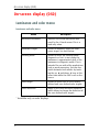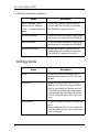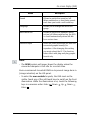
1
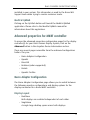
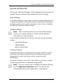
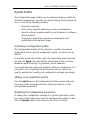
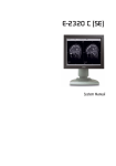
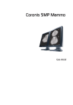
Coronis Elite
Online user guide
(This page intentionally left blank.)
2
Table of contents
Table of contents
Table of contents ..................................................................... 3
Using the online User Guide.................................................... 5
Sources of information .................................................................... 6
User interface ................................................................................... 7
Graphic board information ...................................................... 9
BARCO Controller Control Panel Settings ........................................ 10
Languages supported ............................................................. 10
Barco Driver Properties........................................................... 11
Accessing the Barco tab .................................................. 11
Using the Barco tab ......................................................... 11
Advanced properties for MXRT controller .............................. 13
Barco Adapter Configuration........................................... 13
OpenGL and Direct3D ...................................................... 15
Rotation............................................................................ 16
(Device) Details ............................................................... 16
OpenGL Profiles ............................................................... 17
Advanced Properties for BarcoMed Coronis or
BarcoMed Nio.......................................................................... 18
Palette modes ................................................................. 18
Drawing Modes ............................................................... 20
Monitor Configuration ..................................................... 22
Graphics Board................................................................. 22
Device Details .................................................................. 22
Configuring the Windows desktop................................................ 24
Display information ............................................................... 25
Precautions..................................................................................... 26
Display controls .............................................................................. 28
Overview of controls............................................................... 28
How to use the controls ......................................................... 29
3
Table of contents
Stand-by switching ................................................................. 31
On-screen display (OSD)................................................................ 32
Luminance and color menu.................................................... 32
Display Function menu ........................................................... 34
Settings menu......................................................................... 38
Information menu................................................................... 40
Changing the viewing mode......................................................... 41
Enabling/disabling User Controls.................................................. 42
Switching Power LED on/off ......................................................... 43
Switching DPMS on/off ................................................................. 44
Changing Display Functions........................................................... 46
Concepts .................................................................................. 46
Display function selection ...................................................... 46
ALC & DICOM Options.............................................................. 48
DICOM offset .................................................................... 48
Reading room selection .................................................. 49
Reading room definition ................................................. 50
Adjusting Luminance and Color..................................................... 52
Concepts .................................................................................. 52
Luminance target (grayscale displays).................................. 52
Color target (color displays) ................................................... 53
Selecting a color target ................................................... 53
Color target definition ..................................................... 54
Barco web sites ..................................................................... 57
4
Using the online User Guide
5
Sources of information
Sources of information
Overview of product documentation
Document
6
Content
Quick install sheet
(poster in box)
Gives a short overview of the installation of a complete system.
Getting started guide
(booklet in box)
Gives a detailed description of the
installation and connection of a complete system.
Online user guide
(html file installed on PC)
Gives a detailed description of how to
operate the display using its local controls and on-screen display (OSD). This
document is to be consulted on screen.
User manual
(PDF file on CD-ROM)
Contains the same information as the
online user guide, but is laid-out for
printing.
User interface
User interface
Items in the navigation frame
Item
Description
Contents
Shows the complete content of the help
system.
Index
Shows the available help topic entries in
alphabetic order.
Search
Allows to search for a particular entry in
the help system.
Favorites
Allows to add and remove help topics to
a list of favorites. (requires cookies)
Items in the toolbar frame
Item
Description
Synchronize
Press this button to show the location of
the help item in the Contents.
Previous
Press this button to move to the previous help topic.
Next
Press this button to move to the next
help topic.
Related topics
Press this button to display related topics (if available).
E-mail
Press this button to e-mail the current
help topic.
Print
Press this button to print the current
help topic.
7
User interface
Item
Bookmark
8
Description
Press this button to bookmark the current help topic. This topic will then
appear in the web browser’s Favorites
menu. (requires cookies)
Graphic board information
9
BARCO Controller Control Panel Settings
BARCO Controller Control Panel Settings
This chapter describes how to configure the displays in your BARCO
CORONIS Display System using the tools available through the
Advanced button on the Settings tab of the Windows Display Control
Panel.
Note: If you purchased Barco Medical Displays only and not a
complete BARCO CORONIS Display System you will need to refer to
the user manual for the display controller you are using.
Languages supported
The BarcoMed tabs support the following languages:
English (U.S) (default)
Dutch
French
German
Italian
Japanese
Korean
Simplified Chinese
Traditional Chinese
Spanish
Note: To change between the languages select the correct
region via the Regional Settings Control Panel in your machine’s
Start > Settings > Control Panel.
10
BARCO Controller Control Panel Settings
Barco Driver Properties
Accessing the Barco tab
Note: You must have logged on to Windows using an account
with administrator privileges in order to use the Barco portions
of the Windows Display Control Panel to change any display
settings.
1. Open the Windows Display Control Panel by one of the methods
below:
a) Start > Settings > Control Panel > Display
b) Open the “Display Properties Control Panel” by right
clicking in an empty area on the desktop, then select
Properties.
c) Windows Vista: Right click in an empty area on the
desktop, select “Personalization”, then click on“Display
Settings”.
2. Click on the Settings tab (The Settings tab is not present in
Vista).
3. Select the rectangle that represents the BARCO CORONIS Display
whose settings you wish to change.
4. Click on the Advanced Settings button.
5. Select the Barco tab from the Properties screen.
Using the Barco tab
The Barco tab is divided into three sections. The first section provides
information about the graphics controller and allows access to the
graphics controller advanced configuration pages. The second section
provides information about the display. The bottom section allows
access to two Barco tools, Barco System Report and MediCal QAWeb.
Also, there is a active link to the Barco Medical Imaging Systems web
site.
11
BARCO Controller Control Panel Settings
Figure 1: Ex: Barco Tab
Display Information
Name: Displays the model name of the display.
Serial Number: Displays the serial number of the display.
Backlight LifeTime: This is the amount of time in hours that the
backlight has been on. The backlight will typically last a very long
time, but will only be able to hold the recommended calibrated
luminance for a certain amount of time, after which time it will
become slowly dimmer.
Barco system report
The Barco System Report, also known as BarcoMed SelfExam, is a
wizard based tool which collects data about the components that are
12
BARCO Controller Control Panel Settings
installed in your system. This information is used by the Barco MIS
Support team when trying to resolve customer issues.
MediCal QAWeb
Clicking on the QA Web button will launch the MediCal QAWeb
application. Please refer to the MediCal QAWeb manual for
information about this application.
Advanced properties for MXRT controller
To access the advanced properties configuration pages for the display
controller(s) for your BARCO CORONIS Display System, click on the
Advanced button in the Graphics Device Information section.
There are several pages accessible from the advanced configuration
button. They are:
• Barco Adapter Configuration
• OpenGL
• Direct3D
• Rotation (when supported)
• Details
• OpenGL Profiles
Barco Adapter Configuration
The Barco Adapter Configuration page allows you to switch between
the following monitor configurations and display options for the
displays connected to a Barco MXRT controller:
Display Layout
• DualView
Both displays are enabled independent of each other.
• SingleView
A single large desktop spans across both displays.
13
BARCO Controller Control Panel Settings
• Clone
The primary display is cloned to the secondary display.
Color Format
• 24-Bit TrueColor Mode
• 30-Bit TrueColor Mode (HDR)
Display Resolution
• Sets display resolution for 1 or 2 displays.
Note: To switch out of SingleView or Clone mode, the
buttons in this Control Panel page must be used. The main
Windows Control Panel cannot be used. Depending on your
system, certain configurations can be disabled.
Note: Clone Mode is supported for two color displays or
projectors in 32bpp. Clone mode is not supported on grayscale
displays. Also, HDR is not supported while in Clone Mode.
When choosing Clone Mode under the Barco Adapter
Configuration page, if two displays are enabled, then the larger
of the two current resolutions will be used. If only one of the
two displays is enabled, the enabled displayís current resolution
will be used.
When the resolution set for clone mode is larger then the
maximum supported on a display, the resolution set on the
Master will automatically be scaled to maximum resolution of
the Cloned display. If the Scale to Display Preferred Mode is
checked, the maximum resolution will be the EDID preferred
mode. If it is unchecked, then it will be the largest mode in the
Cloned displays mode list. Clone mode can only be exited
through the Barco Adapter Configuration page in the Barco
Advanced Control Panel.
Note: Not all options are available at all times. Please select
the help tips in the driver software for more information.
14
BARCO Controller Control Panel Settings
OpenGL and Direct3D
The OpenGL and Direct3D pages of the Advanced Properties page are
divided into two sections: Main Settings and Custom Settings.
Main Settings
In the Main Settings section there is a slider bar which allows the user
to adjust the OpenGL or Direct3D settings for optimum performance,
optimum quality or for a point in between. There is also a checkbox
provided for enabling Custom Settings.
Custom Settings
Note: Barco recommends that you use the default settings,
unless your viewing application vendor provides detailed
information on custom settings.
In the Custom Settings section the user can fine tune the following
options:
• Anisotropic filtering
• SMOOTHVISION
• Wait for Vertical Sync
Antisotropic filtering
Anisotropic filtering is a technique that preserves detail on surfaces
that have three-dimensional perspective and fade away into the
background. It works best when used in conjunction with
Mipmapping.
Anisotropic filtering can be set to favor either an increase in system
processing performance or improved image quality.
Note: If you are unsure how to configure anisotropic filtering,
use the Application Preference option. Your display will
automatically adjust to the application’s requirements.
15
BARCO Controller Control Panel Settings
Please refer to the on-line help (click on the “?” in the control panel’s
openGL tab) for more information on using advanced features such as
Anisotropic Filtering.
SMOOTHVISION
The Advanced Settings tab enables you to apply ATI’s SMOOTHVISION
technology for full-scene anti-aliasing. SMOOTHVISION improves
image quality by removing jagged edges (anti-aliasing) from 3D
images, resulting in smoother, more natural looking objects.
Please refer to the on-line help for more information on using
advanced features such as SMOOTHVISION.
Wait for Vertical Sync
• For OpenGL the default setting is Default Off.
• For Direct3D the default setting is Application Preference.
Please refer to the on-line help for more information on using
advanced features such as Wait for Vertical Sync.
Rotation
The Rotation page is visible only when the display connected to the
current (active) head of your Barco MXRT display controller does not
support rotation internally. The Rotation feature allows the user to
rotate the Windows desktop to match the physical orientation of the
display.
(Device) Details
The Details page provides detailed information about the display
controller connected to the active display. This information is useful in
debugging issues that may occur when using your BARCO CORONIS
Display(s).
16
BARCO Controller Control Panel Settings
OpenGL Profiles
The Configuration page enables you to customize display profiles for
individual applications. Typically, you would change these settings for
one or more of the following reasons:
• Diagnostic purposes.
• Fine-tuning a specific application/system configuration.
• Specific settings recommended by your hardware or software
documentation.
• Tuning your application/system environment for best
performance and memory usage.
Activating a configuration profile
The Configuration Profiles list box displays a number of common
applications whose optimal configuration profile are factory-set by
default.
To activate a particular profile, select the application name from the
list and click Apply. This will add the information to the necessary
Windows registry settings. If prompted, restart Windows.
If you subsequently experience problems with your application, or if
you want to try to optimize the performance of your system on
specific applications, modify your configuration settings accordingly.
Adding a new application profile
Click the Add button in the Configuration Profiles section and enter
the name of the new application for which you want to set the
configuration parameters.
Modifying the configuration parameters
To change the configuration settings of a specific application, select
the name of that application from the Configuration Profiles list box.
Click the Modify button. Now select or clear the rest of the
17
BARCO Controller Control Panel Settings
configuration controls on this tabbed dialog to obtain the desired
display parameters for the selected application.
To remove the selected configuration profile completely, select the
name of the application from the Configuration Profiles list box and
click Delete.
Note:
You cannot delete the factory-set configuration profiles.
Click the Apply or OK button to enable your Configuration settings.
Advanced Properties for BarcoMed Coronis or
BarcoMed Nio
Palette modes
From the Barco
palette modes.
Drawing Modes tab you can select one of four
• Color to Gray compatibility
• User Modifiable Color Palette
• Static Gray Palette including standard system colors
• Static Gray Palette with NO system colors
User Modifiable Color Palette
This option allows applications to modify the palette contents
dynamically. As indicated in figure 2, this mode reserves the first 10
and last 10 entries in the palette for the Windows operating system,
but applications can manipulate the middle 236 entries. This is the
standard palette mode as configured by Windows.
18
BARCO Controller Control Panel Settings
Figure 2: User Modifiable Palette
Note: If you are unsure whether or not your application
requires this “User Modifiable Color” mode, contact your
application provider.
Static Gray Palette including standard system colors
This option sets the palette to be a static set of 256 gray values.
Applications are denied the ability to dynamically change or allocate
palette entries. This prevents palette conflicts between applications,
which can cause image color values to appear distorted in the
background application.
As shown in figure 3, the 20 standard system colors are converted
from RGB to gray values. The rest of the 236 entries from index 10 to
245 contain the missing gray values so that the palette has the full
256 gray values within it.
Figure 3: Static Gray Palette with system colors
Note: If you are unsure whether or not your application
requires this “Static Gray Palette with System colors” mode,
contact your application provider.
Static Gray Palette with NO system colors
This option sets the palette to be a static linear ramp of 256 shades of
gray. Therefore, applications are denied the ability to dynamically
change or allocate palette entries. This prevents palette conflicts
19
BARCO Controller Control Panel Settings
between applications, which can cause image color values to appear
distorted in the background application.
As shown in figure 4, each of the 256 entries in the palette has an
RGB value of (i, i, i) where i is the index from 0 to 255.
Figure 4: Static Gray Palette with NO system colors
If you wish to use a static gray palette we recommend using the
“Static Gray Palette including Standard System Colors” option instead
of this one. This is due to the fact that some applications assume that
the first and last 10 entries of the palette are the standard system
colors. In this palette mode, these entries are made up from entries in
the bottom or the top of the gray ramp.
Note: If you are unsure whether or not your application
requires this “Static Gray Palette with NO System colors” mode,
contact your application provider.
More information about Palette Modes is available through the
on-line help.
Drawing Modes
In the Drawing Mode section you can choose from the following
Drawing Modes. If any of the options in this section are grayed out,
then they are not available for the model controller with which you
are working.
Enable DirectDraw
This option allows the user to enable or disable DirectDraw.
DirectDraw is a software interface that provides direct access to
20
BARCO Controller Control Panel Settings
display devices while maintaining compatibility with the Windows
graphics device interface (GDI). DirectDraw is enabled by default.
More information about DirectDraw is available through the on-line
help.
Enable Dithering
This option allows the user to enable or disable dithering. Dithering is
a technique for increasing the perceived range of colors in an image
at the cost of spatial resolution.
Note: This option is only available when the User Modifiable
Palette mode is selected. If either the Static Gray Palette
including Standard System Colors mode or the Static Gray
Palette with NO System colors mode is selected, the “Enable
Dithering” check box will be grayed-out, and dithering will be
automatically disabled.
Disable 10-bit grayscale
Use this option for standard Windows®-based applications that
require 8-bit color support (256 colors), such as Internet Explorer,
Excel, etc.
Do not use this option for applications that require 10-bit pixel
support (1024 simultaneous shades of gray) and use extended depth
graphic libraries such as WinBarco.
Description of 10-bit grayscale: To show 1024 simultaneous
shades of gray all BarcoMed “H” series display controllers, such
as the BarcoMed 5MP2FH, BarcoMed Coronis or BarcoMed
Coronis 5MP for example, run in extended depth (10-bit) mode
by default.
Implications: When turned on the “Disable Extended Depth”
option causes a BarcoMed Coronis display controller to run in
8-bit mode, which results in increased performance since the
frame buffer is set to run with 8-bit pixels. While this option may
be used with applications that normally require 10-bit support,
21
BARCO Controller Control Panel Settings
there will be a loss of pixel depth, i.e. 256 shades of gray
instead of 1024 simultaneous shades of gray.
Disable RGB To Static Gray Color Translation
Select Disable RGB To Static Gray Color Translation if you wish to have
RGB values equally weighted, with 1/3 each. When not selected, then
the International Commission on Illumination (CIE – Commission
Internationale de I’Eclairage) model will be adapted, which weights
the colors as 59% Green, 30% Red, 11% Blue.
Monitor Configuration
The Monitor configuration page allows you to switch between the
following monitor configurations for the displays connected to a
BarcoMed controller:
• SingleView
A single large desktop spans across both displays.
• DualView
Both displays are enabled independent of each other.
Graphics Board
Update Firmware... Button: Clicking this button will launch the
BarcoMed Hardware Configuration utility. This program allows the user
to flash update the firmware stored in the ROM of the currently
selected BarcoMed display controller. The BarcoMed Hardware
Configuration utility is implemented in a Wizard format, which guides
the user through the flash update procedure. The user will be
prompted to select a firmware update file to use for the update
process. This file will be provided by Barco Medical Imaging Systems if
and when a firmware update is required.
Device Details
From the Device Details tab you can access the Device Details page,
which provides detailed information about the display controller
22
BARCO Controller Control Panel Settings
connected to the active display. This information is useful in
debugging issues that may occur when using your Barco Coronis
Display(s).
23
Configuring the Windows desktop
Configuring the Windows desktop
Note: If you are using a color display in conjunction with your
Barco grayscale display(s) you should configure your desktop
before setting the resolution of your Barco grayscale display(s).
You must have logged on to Windows using an account with
administrator privileges in order to use the Barco portions of the
Windows Display Control Panel to change any display settings.
The recommended configuration for best grayscale image quality
when using a color display in conjunction with your high-resolution
grayscale display(s) is to set the color display as the primary monitor
of the Windows desktop. Then set the colors setting on the “Settings”
tab of the Windows Display Control Panel to the highest possible color
depth (e.g. 32 bits-per-pixel “true color”) supported by the color
display’s controller.
The colors setting for your high-resolution grayscale displays should
be set to 256 colors (8 bits per pixel). You should set the palette
mode for the your high-resolution grayscale displays to Static Gray
palette with NO system colors. This guarantees that all of the 256
gray levels available for GDI graphics will be present. This also
eliminates the danger that colors will change when focus moves
among different applications.
However, if you are using the Color to Gray Compatibility palette
mode, the color setting for your high-resolution grayscale displays
should default to True Color (32 bits per pixel). Even though this
palette mode supports 32 bit True Color, Barco recommends that
when using a using a color display in conjunction with your highresolution grayscale display(s) that you still set the color display as
the primary monitor of the Windows desktop.
24
Display information
25
Precautions
Precautions
1. Optimize the lifetime of your display
Enabling the Display Power Management System (DPMS) of your
display (in the display’s Settings menu) will optimize its diagnostic
lifetime by automatically switching off the backlight when the display
is not used for a specified period of time. By default, DPMS is enabled
on your display, but it also needs to be activated on your workstation.
To do this, go to “Power Options Properties” in the “Control Panel”.
Barco recommends setting DPMS activation after 20 minutes of
non-usage.
2. Use a screen saver to avoid image retention
Prolonged operation of an LCD with the same content on the same
screen area may result in a form of image retention.
You can avoid or significantly reduce the occurrence of this
phenomenon by using a screen saver. You can activate a screen saver
in the “Display properties” window of your workstation.
Barco recommends setting screen saver activation after 5
minutes of non-usage. A good screen saver displays moving
content.
In case you are working with the same image or an application with
static image elements for several hours continuously (so that the
screen saver is not activated), change the image content regularly to
avoid image retention of the static elements.
3. Understand pixel technology
LCD displays use technology based on pixels. As a normal tolerance in
the manufacturing of the LCD, a limited number of these pixels may
remain either dark or permanently lit, without affecting the
26
Precautions
diagnostic performance of the product. To ensure optimal product
quality, Barco applies strict selection criteria for its LCD panels.
To learn more about LCD technology and missing pixels, consult
the dedicated white paper available at www.barcomedical.com.
4. Enhance user comfort
Every Barco multi-head display system is color matched with the
highest specification in the market.
Barco recommends keeping color-matched displays together.
Furthermore, it is important to use all displays of a multi-head
configuration at the same rate to preserve color matching
throughout the economic lifetime of the system.
5. Maximize Quality Assurance
The ‘MediCal QAWeb’ system offers online service for high-grade
Quality Assurance, providing maximum diagnostic confidence and
uptime.
Learn more and sign up for the free MediCal QAWeb Essential
level at www.barcomedical.com/qa
27
Display controls
Display controls
Overview of controls
The front controls are soft touch keys.
When you touch any of them while no on-screen display (OSD) is on
the screen, the front illumination is switched on for a few seconds.
When you touch a key again while the illumination is on, the function
of the key is executed.
Figure 5: Front view
1. Left/Down
To move down or decrease values in the OSD.
2. Right/Up
To move up or increase values in the OSD.
3. Enter
28
Display controls
To display the OSD (on-screen display). In the OSD, this button
acts as Enter button to make selections.
4. Standby
To put the display in standby mode.
5. Ambient light sensor
Senses the ambient light around the display. The ambient light
measurement can be taken into account in the DICOM display
function calibration.
6. Power LED
Indicates the display’s power status.
Green: Display is on (when enabled in the OSD).
Orange: Display is in Standby power-saving mode.
Off: Display is disconnected from the power or the LED’s on state
is disabled in the OSD.
Note: When the LED is disabled in the OSD, it will still be
activated (green) when the display is on but does not receive
any video signal.
7. I-Guard sensor
Constantly measures and stabilizes the display light output and
(on a color display only) color temperature.
How to use the controls
1. When the OSD is not on the screen, touch any of the soft touch
keys.
The front illumination is switched on for about 10 seconds.
2. While the illumination is on, touch the Enter
touch key to
display the main menu. It contains several submenus.
29
Display controls
3. To open a submenu, use the Up or Down touch keys to
touch key to open
select the submenu. Next, press the Enter
the submenu.
4. To exit from a submenu, use Up
Next, press Enter .
or Down
to select EXIT.
If you exit from the Main Menu, you exit the OSD.
5. To change an adjustment value or setting, use Up or Down
to select the adjustment or setting. Next, press Enter
to go
into edit mode. This is indicated by the scroll bar becoming
longer.
SETTINGS
DPMS
Power LED
User Controls
EXIT
On
On
On
Figure 6: Setting is selected
SETTINGS
DPMS
Power LED
User Controls
EXIT
On
On
On
Figure 7: Edit mode is active
Use Up or Down to change the value. Use Enter
confirm the change.
to
Changes are saved automatically after confirming.
6. Some items in the menus cannot be changed. They are readonly values, displayed in light gray.
Tip:
While you are adjusting a value:
• Touching Up and Down at the same time resets to the last
stored value.
30
Display controls
• Touching Up and Enter at the same time selects the maximum
value.
• Touching Down and Enter at the same time selects the
minimum value.
While the OSD is not on the screen:
• Touching Up and Down at the same time switches the display
in text editing mode. In this mode the luminance is reduced so
that the display can be used for office applications other than
diagnostic applications.
To switch text mode off again, touch Up and Down again.
Stand-by switching
To switch from on state to stand-by:
1. Touch the Stand-by
touch key.
2. A warning message appears. Press the Stand-by touch key again
to switch the display into stand-by or press any other key to
keep the display in on state.
To switch from stand-by to on state:
1. Touch any of the soft touch keys.
The front illumination is switched on for about 10 seconds.
2. While the illumination is switched on, touch the Stand-by
touch key to switch the display on.
31
On-screen display (OSD)
On-screen display (OSD)
Luminance and color menu
Luminance and color menu
Name
Description
Measured luminance
Indicates the actual luminance measured by the I-Guard sensor. This is a
read-only value.
Luminance target
Allows to manually adjust the luminance target. See note below.
Viewing mode
Allows to select the viewing mode:
Diagnostic or Text. In text mode the
luminance is approximately half of the
luminance in diagnostic mode. This is
intended for use with office applications
such as word processing. You can also
switch between both modes by touching the up
and down
keys at the
same time while the OSD is not on the
screen.
Color target*
Allows to select from a list of factorydefined and user-defined color targets.
Color definition*
Jumps to the color definition submenu,
which allows to change the definition of
the user-defined color targets.
* Available only on color displays
32
On-screen display (OSD)
Note: When you change the luminance target, the display will
adjust its backlight to reach the target. This can be seen in the
Measured luminance line.
When the luminance target cannot be reached, e.g., due to aging of
the backlight, the Measured luminance line changes to Minimum
value reached or Maximum value reached.
Color definition submenu*
* Available only on color displays
A color target is defined by its luminance target and color
temperature. The color definition submenu allows to edit these
values.
Name
Description
Color name
Indicates the color target you are editing. You can select another color target
to edit by using the Up
and Down
touch keys.
Luminance target
Allows to select the luminance target
that corresponds to the color target.
Defined in
Indicates how the color temperature is
defined: in (x,y) co-ordinates or Kelvin
(K). You can switch between both by
using the Up
and Down
touch
keys.
This function is available only when the
User color target is selected.
x
Allows to define the x co-ordinate of the
color temperature that corresponds to
the color target.
This function is available only when the
color target is defined in (x,y) co-ordinates.
This function is not available when the
Native White color target is selected.
33
On-screen display (OSD)
Name
Description
y
Allows to define the y co-ordinate of
the color temperature that corresponds
to the color target.
This function is available only when the
color target is defined in (x,y) co-ordinates.
This function is not available when the
Native White color target is selected.
Color temperature
Allows to define the color temperature
that corresponds to the color target in
Kelvin units.
This function is available only when the
color target is defined in Kelvin units.
This function is available only when the
User color target is selected.
Restore factory x,y values
Allows to reset the (x,y) co-ordinates of
the color temperature to the factory values.
This function is not available when the
Native White color target is selected.
Display Function menu
Display function menu
Name
34
Description
Display function
Allows to select from a list of predefined display functions.
If the DICOM DF is selected, a number of
additional settings is available.
ALC & DICOM options
Jumps to the ALC & DICOM Options submenu, which allows to edit the settings
for the DICOM display function.
This function is available only when the
DICOM DF is selected.
On-screen display (OSD)
ALC & DICOM Options submenu
Name
Description
Measured ambient light
Indicates the ambient light actually
measured by the ambient light sensor
on the front of the display. This is a
read-only value.
Averaged ambient light
Shows the average of the measured
ambient light since the display was
switched on.
When you execute the function “Measure ALC Value”, this value will be
stored as the Measured ALC correction
value for the selected reading room,
unless this value is higher than the
maximum ambient light determined for
the selected reading room.
Correction value
Shows the ambient light correction
value that is taken into account in the
calculation of the display function.
DICOM offset
When Continuous DICOM ALC is switched
off, the DICOM DF is recalculated at the
moment the DICOM Offset is changed,
taking the new DICOM Offset into
account.
• When set to “Dark Room”, the
ambient light is not taken into
account.
•
When set to “Preset”, a preset
ambient light value determined by
the selected reading room is taken
into account.
•
When set to “Measured ALC”, the
averaged ambient light, determined
by the selected reading room, is
taken into account.
35
On-screen display (OSD)
Name
Description
Reading room
Allows to select from a pre-defined list
of reading room types.
You must select a reading room that
corresponds to the type of room the display is installed in.
Reading room def.
Jumps to the reading room definition
submenu, which allows to edit the
reading room condition settings.
Calibration info
Jumps to the calculation information
submenu, which displays information
about the values taken into account to
recalculate the DICOM DF.
Reading room definition submenu
Name
36
Description
Measured ambient light
Indicates the ambient light actually
measured by the ambient light sensor
on the front of the display. This is a
read-only value.
Averaged ambient light
Shows the average of the measured
ambient light since the display was
switched on. This is a read-only value.
Reading room
Indicates the reading room type you are
editing. You can select another room to
edit by using the Up
or Down
touch keys.
On-screen display (OSD)
Name
Description
Max. ambient light
This indicates the maximum ambient
light that corresponds to the selected
reading room.
If the measured ambient light is higher
than the value entered here, you should
take measures to darken the room or
select another reading room type.
Preset corr. value
This value is taken into account in the
calculation of the DICOM DF if Continuous DICOM ALC is switched off and
DICOM Offset is set to “Preset”.
To each reading room type corresponds
another preset value.
Measure ALC value
The value shown here is taken into
account in the calculation of the DICOM
DF if Continuous DICOM ALC is switched
off and DICOM Offset is set to “Measured ALC”.
When you select this line and press
Enter
, the actual averaged ambient
light value is stored here, overwriting
the former value.
However, if the averaged ambient light
value is higher than the maximum
ambient light value that corresponds to
the selected reading room, a warning is
displayed prompting you to dim the
light in the room, and the value will be
limited to the maximum ambient light
value.
If you dim the light in the room you can
execute the Measure ALC Value function
again to enter the new, lower value.
37
On-screen display (OSD)
Calibration Information submenu
Name
Description
Preset ambient value /
Measured ALC ambient
value / Average ambient
value
Shows the ambient light correction
value taken into account to calculate
the DICOM DF, expressed in lux.
Bright luminance
Shows the bright luminance value taken
into account to calculate the DICOM DF.
Dark luminance
Shows the dark luminance value taken
into account to calculate the DICOM DF.
Ambient correction
Shows the ambient light correction
value taken into account to calculate
the DICOM DF, expressed in cd/m².
Settings menu
Name
38
Description
DPMS
Allows to switch the display power
management system on/off. See note
below.
Power LED
Allows to switch the power LED’s on
state on/off. The LED's orange DPMS
state is not influenced by this setting.
So, when the display goes into powersaving mode, the LED will turn orange,
even if it was switched off by this setting.
User controls
Allows to disable the touch keys on the
front.
When switched off, the user cannot display the OSD until the user controls keycode is entered.
On-screen display (OSD)
Name
Description
Sound
Allows to switch the sound on/off.
When switched on, a short beep sounds
each time you touch a soft touch key.
Language
Allows you to change the menu language.
Auto menu exit
Allows to switch the automatic menu
exit on/off. When switched on, the OSD
is closed automatically when left idle
for a certain time.
Preferred input
Select the video resolution you wish the
connected graphic board(s) to
reproduce. After changing this setting
you must reboot the PC. This function
takes effect with plug-and-play graphic
boards only.
Note:
• The DPMS system will power down the display when the
connected computer is left idle for a certain time.
Barco recommends to switch DPMS on to prevent image burn-in
(image retention) on the LCD panel.
• To enter the user controls keycode, the OSD must not be
visible. Touch any of the soft touch keys to switch on the front
illumination. While the illumination is on, touch the following
keys in successive order: Enter , Down , Up , Down ,
Enter .
39
On-screen display (OSD)
Information menu
Information
40
Name
Description
Product
The display type.
Serial No
Indicates the display serial number.
SW Version
Displays the current internal software version.
Display runtime
Indicates the total time the display has been
operating, including the time in stand-by.
Backlight runtime
Indicates the total time the display has been
operating, excluding the time in stand-by.
Changing the viewing mode
Changing the viewing mode
About viewing modes
The display contains two viewing modes. Diagnostic viewing mode
provides the full calibrated luminance. This mode is intended for using
the display in diagnostic applications.
In Text mode, the luminance is approximately half of the luminance in
Diagnostic mode. This is intended for using the display with office
applications such as word processing.
Switching viewing modes by means of the keys
While the OSD is not on the screen, touch the Up and Down
touch keys at the same time. As a result the display switches to
another viewing mode. The viewing mode is indicated by a message
that appears for a few seconds after switching the viewing mode.
Switching viewing modes by means of the OSD menus
You can also switch viewing modes in the Luminance and color menu.
41
Enabling/disabling User Controls
Enabling/disabling User Controls
To disable the user controls:
1. Open the OSD main menu.
2. Open the Settings menu.
3. Select User Controls.
4. Select Off.
5. Return to the Settings menu.
6. Exit the OSD
Now the user cannot display the OSD again until the user controls
keycode is entered (see below).
To enable the user controls again:
1. To enter the user controls keycode, the OSD must not be visible.
2. Touch any of the soft touch keys to switch on the front
illumination.
3. While the illumination is on, touch the following keys in
successive order:
Enter
, Down
, Up
, Down
, Enter
.
As a result, the User Controls setting in the Settings menu is switched
on again.
42
Switching Power LED on/off
Switching Power LED on/off
To switch the power LED on/off:
1. Touch any of the soft touch keys.
The front illumination is switched on.
2. While the illumination is on, touch the Enter
display the main menu.
touch key to
3. Use the Up or Down touch keys to select the Settings
to open the menu.
menu. Use Enter
4. Use Up or Down
into edit mode.
to select Power LED. Use Enter
5. Use Up
to select On or Off.
6. Use Enter
or Down
to go
to save the changes.
Note:
• When the display is switched in stand-by, the power LED will
turn orange, even if the power LED setting is switched off.
• When the power LED setting is switched off, the LED will still
turn on (green) when the display is on but receives no video
signal.
43
Switching DPMS on/off
Switching DPMS on/off
1. Optimize the lifetime of your display
Enabling the Display Power Management System (DPMS) of your
display (in the display’s Settings menu) will optimize its diagnostic
lifetime by automatically switching off the backlight when the display
is not used for a specified period of time. By default, DPMS is enabled
on your display, but it also needs to be activated on your workstation.
To do this, go to “Power Options Properties” in the “Control Panel”.
Barco recommends setting DPMS activation after 20 minutes of
non-usage.
2. Use a screen saver to avoid image retention
Prolonged operation of an LCD with the same content on the same
screen area may result in a form of image retention.
You can avoid or significantly reduce the occurrence of this
phenomenon by using a screen saver. You can activate a screen saver
in the “Display properties” window of your workstation.
Barco recommends setting screen saver activation after 5
minutes of non-usage. A good screen saver displays moving
content.
In case you are working with the same image or an application with
static image elements for several hours continuously (so that the
screen saver is not activated), change the image content regularly to
avoid image retention of the static elements.
3. Understand pixel technology
LCD displays use technology based on pixels. As a normal tolerance in
the manufacturing of the LCD, a limited number of these pixels may
remain either dark or permanently lit, without affecting the
44
Switching DPMS on/off
diagnostic performance of the product. To ensure optimal product
quality, Barco applies strict selection criteria for its LCD panels.
To learn more about LCD technology and missing pixels, consult
the dedicated white paper available at www.barcomedical.com.
4. Enhance user comfort
Every Barco multi-head display system is color matched with the
highest specification in the market.
Barco recommends keeping color-matched displays together.
Furthermore, it is important to use all displays of a multi-head
configuration at the same rate to preserve color matching
throughout the economic lifetime of the system.
5. Maximize Quality Assurance
The ‘MediCal QAWeb’ system offers online service for high-grade
Quality Assurance, providing maximum diagnostic confidence and
uptime.
Learn more and sign up for the free MediCal QAWeb Essential
level at www.barcomedical.com/qa
To switch DPMS on/off:
1. Touch any of the soft touch keys.
The front illumination is switched on.
2. While the illumination is on, touch the Enter
display the main menu.
touch key to
3. Use the Up or Down touch keys to select the Settings
to open the menu.
menu. Use Enter
4. Use Up or Down
edit mode.
to select DPMS. Use Enter
5. Use Up
to select On or Off.
6. Use Enter
or Down
to go into
to save the changes.
45
Changing Display Functions
Changing Display Functions
Concepts
• The Display Function menu lets you select a display function
(DF).
• When you select the DICOM DF you can define the DICOM DF to
be recalculated taking the ambient light into account.
• The recalculation can be based on an illuminance of 0 lux
(“Dark Room”) or a preset value (“Preset”).
• In the case of “Preset” you must select a reading room that
corresponds to the type of room the display is installed in. E.g.
if the display is installed in a room where CT scans are
observed, the “CT/MR/NM” reading room is the preferred
selection.
• The reading room is defined by:
Maximum Ambient Light defines the maximum light allowed
in this type of room. This value can be adjusted within certain
limits determined by the selected reading room.
Preset Correction Value is the predefined correction value for
this reading room. This value can be adjusted within certain
limits determined by the selected reading room.
• The reading room parameters are pre-defined in the display
according to the AAPM (American Association of Physicists in
Medicine). However they can be changed within certain
limits.
Display function selection
To select a display function (DF):
1. Touch any of the soft touch keys.
The front illumination is switched on.
46
Changing Display Functions
2. While the illumination is on, touch the Enter
display the main menu.
touch key to
3. Use the Up or Down touch keys to select the
to open the menu.
Display Function menu. Use Enter
4. Use Up or Down
go into edit mode.
to select Display Function. Use Enter
5. Use Up
to select the desired DF.
or Down
6. Use Enter
to
to save the changes.
You can select the following DFs:
Name
Description
DICOM
Select a DICOM display function for most
medical viewing applications.
The DICOM function results in more visible grayscales in the images.
Dyn Gamma 2.2
Dyn Gamma 1.8
These are gamma functions that are
shifted to take into account the non-zero
luminance of an LCD panel when driven
with a “black” signal.
They are especially useful in CT applications to improve the perception of low
Haunsfield values.
Native
If you select Native, the native panel
behavior will not be corrected.
Test
This is identical to the Native DF.
Gamma 2.2
Gamma 1.8
Select one of these display functions in
case the display is to replace a CRT display with a gamma of 1.8 or 2.2 respectively.
User
This is a user-definable DF.
47
Changing Display Functions
ALC & DICOM Options
DICOM offset
Introduction
DICOM DF will be recalculated only when another DICOM Offset is
selected. The DICOM DF will be recalculated based on the new offset
setting.
To select a DICOM offset:
1. Select the DICOM display function. See To select a display
function (DF):, on page 46.
2. In the ALC & DICOM Options menu, use Up or Down to
to go into edit mode.
select DICOM Offset. Use Enter
3. Use Up
or Down
4. Use Enter
to select an offset.
to save the changes.
You can select the following offsets:
Value
48
Description
Dark Room
The DICOM DF will be recalculated taking an ambient light value of 0 lux into
account.
This means that the measured ambient
light does not influence the DICOM DF.
Preset
The DICOM DF will be recalculated taking a preset ambient light value into
account. This value is determined by the
selected Reading Room and can be
adjusted manually within certain limits.
Changing Display Functions
Value
Measured ALC
Description
The DICOM DF will be recalculated taking the averaged measured ambient
light value into account that is determined by the selected Reading Room.
This value can be changed by executing
the “Measure ALC Value” function in the
Reading Room Definition submenu.
Reading room selection
This function is available only when the DICOM display function is
selected and Continuous DICOM ALC is off.
To select a reading room setting:
1. Select the DICOM display function. See To select a display
function (DF):, on page 46.
2. In the ALC & DICOM Options menu, use Up or Down to
to go into edit mode.
select Reading Room. Use Enter
3. Use Up or Down to select the reading room that
corresponds to the room type the display is installed in.
4. Use Enter
to confirm the selection.
You can select the following reading room types::
Name
Description
CR/DR/MAMMO
Corresponds to light conditions in diagnostic reading rooms for computed radiology, digital radiology or
mammography. This setting has the
lowest maximum ambient light.
CT/MR/NM
Corresponds to light conditions in diagnostic reading rooms for computed
tomography, magnetic resonance or
nuclear medicine scans.
49
Changing Display Functions
Name
Description
Office
Corresponds to light conditions in office
rooms.
Clinical
Corresponds to light conditions in diagnostic reading rooms for clinical viewing.
Emergency
Corresponds to light conditions in emergency rooms.
Operating
Corresponds to light conditions in operating rooms. This setting has the highest maximum ambient light.
Reading room definition
This function is available only when the DICOM display function is
selected and Continuous DICOM ALC is off.
To modify a reading room definition:
1. Select the DICOM display function. See To select a display
function (DF):, on page 46
2. In the ALC & DICOM Options menu, use Up or Down to
to open the submenu.
select Reading Room Def. Use Enter
3. Select the reading room definition you wish to modify. Thereto,
use Up or Down to select Reading Room. Use Enter
to
go into edit mode. Use Up or Down to select the reading
to confirm the selection.
room. Use Enter
4. To modify the maximum ambient light for this reading room,
use Up or Down to select Max. Ambient Light. Use Enter
to go into edit mode. Use Up or Down to change the
to save the changes.
value. Use Enter
You can change this value within certain limits determined by
the selected reading room.
50
Changing Display Functions
5. To modify the Preset correction value for this reading room, use
to go
Up or Down to select Preset Corr. Value. Use Enter
into edit mode. Use Up or Down to change the value. Use
to save the changes.
Enter
You can change this value within certain limits determined by
the selected reading room.
6. To modify the Measured ALC Value for this reading room, use Up
or Down to select Measure ALC Value. Use Enter
to
execute the function.
If the “Averaged Ambient Light” at that moment is lower than
the defined “Maximum Ambient Light”, the averaged ambient
light value is copied as Measured ALC value. Use Enter
to
store the value.
If the “Averaged Ambient Light” at that moment is higher than
the defined “Maximum Ambient Light”, the display will prompt
a warning for the user to take measures to adapt the ambient
light in the room to the selected reading room. Proceed as
follows:
• Use Enter . As a result the Measured ALC value will be
limited to the maximum ambient light value. Use Enter
again to store the value.
• However, if you wish to adapt the ambient light
conditions to the definition of the selected reading room,
dim the light in the room so that the measured ambient
light becomes lower that the maximum ambient light.
• Then use Enter
again to execute the Measure ALC
Value function once more. As a result the actually
measured ambient light value will be copied as
Measured ALC Value. Finally use Enter
again to store
the value.
51
Adjusting Luminance and Color
Adjusting Luminance and Color
Concepts
• On a grayscale display you can adjust the luminance target.
On a color display you can adjust the color target.
• The color target combines the luminance target and color
temperature.
• The color temperature can be defined in Kelvin units or (x,y)
co-ordinates.
• After changing the target, the display’s backlight and color
amplifiers (color displays only) will be adjusted until the
target is reached.
• The I-Guard sensor constantly measures the luminance and
color temperature (color displays only). These measurements
are used to adjust and stabilize the luminance and color
temperature (color displays only).
Luminance target (grayscale displays)
To change the luminance target:
1. Touch any of the soft touch keys.
The front illumination is switched on.
2. While the illumination is on, touch the Enter
display the main menu.
touch key to
3. Use the Up or Down touch keys to select the Luminance
to open the menu.
menu. Use Enter
4. Use Up or Down to select Luminance Target. Use Enter
to go into edit mode.
5. Use Up
52
or Down
to adjust the luminance target.
Adjusting Luminance and Color
6. Use Enter
to save the changes.
Color target (color displays)
Selecting a color target
To select a color target:
1. Touch any of the soft touch keys.
The front illumination is switched on.
2. While the illumination is on, touch the Enter
display the main menu.
touch key to
3. Use the Up or Down touch keys to select the Luminance
to open the menu.
and Color menu. Use Enter
4. Use Up or Down
into edit mode.
to select Color Target. Use Enter
5. Use Up
to select the desired color target.
or Down
6. Use Enter
to go
to save the changes.
You can select the following color targets:
Name
Description
Clearbase
Simulation of the clearbase film color
temperature
Bluebase
Simulation of the bluebase film color
temperature
Native white
The native, unmodified color temperature of the LCD panel.
User
A completely modifiable color target.
53
Adjusting Luminance and Color
Color target definition
Note: For the Native White color target, only the luminance
target can be modified. For Clearbase and Bluebase the
luminance target and color temperature in (x,y) co-ordinates can
be modified. The User color target can be modified completely.
To modify the color target definition:
1. Touch any of the soft touch keys.
The front illumination is switched on.
2. While the illumination is on, touch the Enter
display the main menu.
touch key to
3. Use the Up or Down touch keys to select the Luminance
to open the menu.
and Color menu. Use Enter
4. Use Up or Down
open the submenu.
to select Color Definition. Use Enter
to
5. Select the color target you wish to modify. Thereto, use Up or
to go into edit
Down to select Color Name. Use Enter
mode. Use Up or Down to select the color target. Use Enter
to confirm the selection.
6. To modify the luminance target, use Up or Down to select
to go into edit mode. Use Up
Luminance Target. Use Enter
or Down to change the value. Use Enter
to save the
changes.
7. To modify the units in which the color temperature is defined
(only for User color target), use Up or Down to select
to go into edit mode. Use Up or
Defined in. Use Enter
Down to change the units: Kelvin units or (x,y) co-ordinates.
to save the changes.
Use Enter
8. To modify the color temperature in Kelvin units, first make sure
the color target is defined in Kelvin units (see step 5). Use Up
or Down to select Color Temperature. Use Enter
to go into
54
Adjusting Luminance and Color
edit mode. Use Up or Down
to save the changes.
to change the value. Use Enter
9. To modify the color temperature in (x,y) co-ordinates, first make
sure the color target is defined in (x,y) co-ordinates (see step 5).
Use Up or Down to select x or y. Use Enter
to go into edit
mode. Use Up or Down to change the value. Use Enter
to save the changes.
Tips
• If you only need to change the luminance target, it is not
necessary to open the Color Definition submenu. You can
change the luminance target in the Luminance and Color
menu. The new value will automatically be saved in the color
definition as well.
• You can restore the (x,y) values to factory defaults by
selecting Restore Factory x,y values.
55
Adjusting Luminance and Color
(This page intentionally left blank.)
56
Barco web sites
Visit Barco at:
http://www.barco.com
Visit Medical Imaging at:
http://www.barco.com/medical
57
B4100533-02
September 2009
Barco nv Medical Imaging
President Kennedypark 35
B-8500 Kortrijk, Belgium
www.barco.com