1
VG4 Modular Camera Series
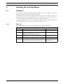
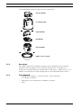
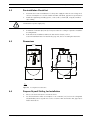
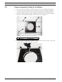
4.9
Installing the In-Ceiling Mount | en
83
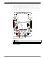
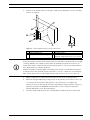
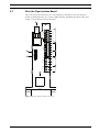
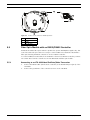
Align and Install Camera Module
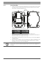
The Camera Module connector attaches to the In-Ceiling Housing CPU board.
1.
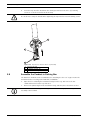
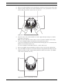
Align the yellow locking tab on the base of the Camera Module to the yellow label on the
CPU Module and press the camera base onto its connector.
2.
Then rotate the camera clockwise (approximately 60 degrees) until it locks in position.
Figure 4.12
4.10
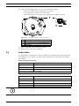
Install Camera Module and Bubble
Attach Bubble
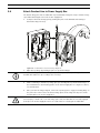
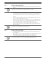
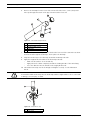
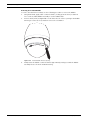
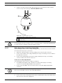
The Dome Bubble/trim assembly attaches to the In-Ceiling Housing.
1.
Place the bubble over the Camera Module, and align it until it settles.
2.
Rotate the bubble clockwise until it locks in position. See Figure 4.12, Page 83.
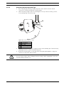
NOTICE! The dome bubble comes assembled with a white trim ring. An optional black trim
ring is supplied separately. To replace the white trim ring, remove the four (4) Phillips head
screws from the inner ring and remove the white trim ring. Then place the black trim ring over
the inner ring, and replace and tighten the four (4) screws.
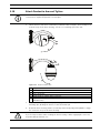
Figure 4.13
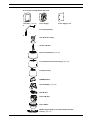
1
2
Bosch Security Systems, Inc.
In-Ceiling Bubble
In-ceiling Housing 3
Ceiling
4
Camera Module
Bubble
Installation Manual
F.01U.162.025 | 6.0 | 2010.03