1
2. INSTALLATION
2.12
Universal Status Monitor (USM)
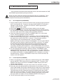
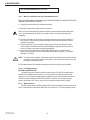
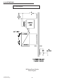
The optional, USM status monitoring upgrade plugs directly into the APM logic card.
NOTE: The Main Circuit Module assembly must be completely removed from the power
module when installing the USM (see section 2.8). Status monitoring interfaces are listed
according to their manufacturer, along with the associated parts. The USM can also accommodate a tamper switch assembly to indicate unauthorized enclosure entries.
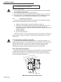
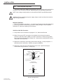
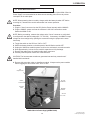
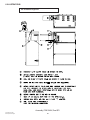
1. Remove the APM logic card from the Main Circuit Module assembly (if installed).
Verify that the APM's Auto-Equalize and Self-test switches are in their desired
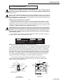
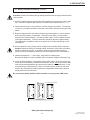
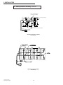
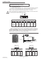
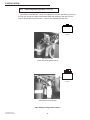
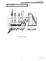
positions. Plug the USM logic card into connector J3 (page 20) located on
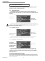
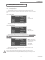
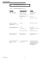
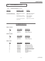
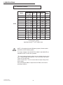
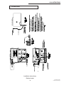
the component side of the APM card. Set the USM switches according to the status
monitoring system you will be using (see following page). Plug the card into the Main
Circuit Module assembly.
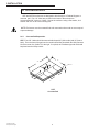
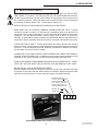
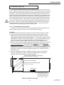
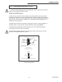
2. If a main board IC upgrade is included, carefully remove the IC (U8) from the main
board assembly. Replace it with the one included with the USM upgrade kit. Position the IC with the notch to the left (pin 1 notch in the lower-left corner). Caution:
The IC is static sensitive and can be easily damaged if not handled properly.
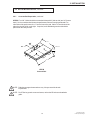
3. Reinstall the Main Circuit Module assembly.
NOTE: Make sure the assembly slides straight in and seats firmly into the card edge
connector.
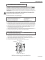
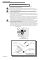
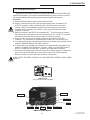
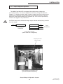
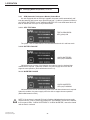
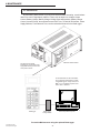
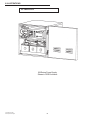
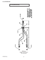
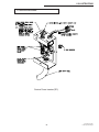
4. Plug the communications cable into the USM connector.
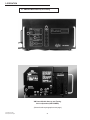
5. The cable fits in one direction only with the incoming cables to the right (see page 25).
6. Test the unit for normal operation.
24
017-720-B2-001 03/97
©1997Alpha Technologies