1
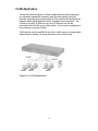
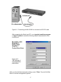
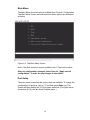
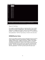
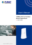
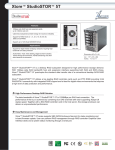
MIL-S1600
16 port Ethernet 10/100 Mbps Switch
User’s Guide
With optional 100FX Modules --SC, ST, MTRJ and VF-45 connectors
Regulatory Approval
- FCC Class A
- UL 1950
- CSA C22.2 No. 950
- EN60950
- CE
- EN55022 Class A
- EN55024
Canadian EMI Notice
This Class A digital apparatus meets all the requirements of the Canadian Interference-Causing Equipment
Regulations.
Cet appareil numerique de la classe A respecte toutes les exigences du Reglement sur le materiel brouilleur du
Canada.
European Notice
Products with the CE Marking comply with both the EMC Directive (89/336/EEC) and the Low Voltage Directive
(73/23/EEC) issued by the Commission of the European Community Compliance with these directives imply
conformity to the following European Norms:
-
EN55022 (CISPR 22) - Radio Frequency Interference
EN61000-X - Electromagnetic Immunity
EN60950 (IEC950) - Product Safety
Five-Year Limited Warranty
MiLAN Technology warrants to the original consumer or purchaser that each of it's products, and
all components thereof, will be free from defects in material and/or workmanship for a
period of five years from the original factory shipment date. Any warranty hereunder is
extended to theoriginal consumer or purchaser and is not assignable.
MiLAN Technology makes no express or implied warranties including, but not limited to, any
implied warranty of merchantability or fitness for a particular purpose, except as expressly set
forth in this warranty. In no event shall MiLAN Technology be liable for incidental or
consequential damages, costs, or expenses arising out of or in connection with the
performance of the product delivered hereunder. MiLAN Technology will in no case cover damages
arising out of the product being used in a negligent fashion or manner.
Trademarks
© 2000 MiLAN, the MiLAN logo and MiLAN Technology are either trademarks or registered
trademarks of Digi International, Inc. in the United States and/or other countries. All other
trademarks are the property of their respective holders.
To Contact MiLAN Technology
For prompt response when calling for service information, have the following information ready:
- Product serial number and revision
- Date of purchase
- Vendor or place of purchase
You can reach MiLAN Technology technical support at:
E-mail: [email protected]
Telephone: +1.408.744.2751
Fax: +1.408.744.2771
MiLAN Technology
1299 Orleans Drive
Sunnyvale, CA 94089-1138
United States of America
Telephone: +1.408.744.2775
Fax: +1.408.744.2793
http://www.milan.com
info @ milan.com
© Copyright 2001 MiLAN Technology
P/N 90000386_A
Contents
1. Introduction…….…………….…………….……….……
1
Features …………………………………………..…..…….……..2
Package Contents ………………………..…..……….………... .3
2. Hardware Description ………………..….…..…...……
4
Front Panel ………………………………………...…...………… 4
LED Indicators …………………………………………………… 5
Real Panel …………………………………………….………….. 6
Desktop Installation ……………………….…….……………….. 6
Rack-mounted Installation …...…………….…………………… 7
3. Optional Fiber Modules ……………..……….………
9
Front Panel …………………………………...…...….….…..… 10
Features/ Specifications …………….………………..….……. 11
Installing 100FX Module ………………………………………. 12
4. Network Application .…………………………………
Small Workgroup ………………………………….......……..…
Segment Bridge …………….……………..…………..….…….
VLAN Application …………………….………………………….
13
13
14
15
5. Network Configuration .……………..……………..…..
16
Connecting a Terminal or PC to the Console port ...………… 17
Port Setup …………………………..…………..
18
SPEED/Duplex Setup ………………………….…...………… 19
VLAN Setup ……………………………………………...……… 20
Trunk Setup ……………………………………………...…… 21
6. Technical Specification .………………………....…..
23
1.
Introduction
The MIL-S1600 is a 16 port 10/100Base-TX switch that can be used to
build high-performance switched networks. The store-and-forward
architecture offers low latency for high-speed networking for workgroups
or departments in any business.
Figure 1-1. The MIL-S1600 switch
The MIL-S1600 has 16 auto-sensing 10/100Base-TX Ethernet RJ-45
ports plus one extension slot for an optional one port 100Base-FX fiber
module enabling long-distance connectivity. The optional fiber modules
support single mode and multi-mode connectors to provide a way to
connect remote sites up to 2 Km (multi-mode) or 15 to 60Km (singlemode). Automatic MDI/MDIX enables connection to another switch or
workstation without changing cabling.
The MIL-S1600 is basically an unmanaged switch but it does supports a
few basic management functions using the console port. The switch does
not support SNMP or an IP address. The console management functions
include trunking, VLANs and port configuration.
1
Features
•
•
•
•
•
•
•
•
•
•
•
•
Conforms to IEEE 802.3, 802.3u, and 802.3x Ethernet Standards
Auto-negotiation for the 10/100Base-TX ports
Automatic MDI/MDIX crossover for each 10Base-T/ 100Base-TX port
One Extension Slot for 100Mbps Fiber
Backpressure for Half-duplex mode, and Flow control for Full-duplex
Store-and-forward switching architecture
8K-entry MAC address table and automatic address learning
4M memory buffer sharing
Console port for limited management support
Non-blocking full wire speed at 3.6 Gbps
LED-indicators for power, trunking, speed, activity, duplex
Standard 19-inch Rackmount size, 1 Ru high
2
Package Contents
Unpack the contents of the MIL-S1600 and verify them against the
checklist below.
n
n
n
n
n
MIL-S1600 Switch
Power Cord
Four Rubber Feet
Console Cable
User Guide
n Rack Mount Ears
Figure 1-2. Package Contents
If any item list above is missing or damaged, please contact your local dealer
for service.
3
2.
Hardware Description
Front Panel
The Front Panel of the MIL-S1600 consists of 16 auto-sensing 10/100BaseTX Ethernet RJ-45 ports, a console port, and an extension slot for a 100BaseFX Fiber Module. The LED Indicators are also located on the front panel of
the switch.
Figure 2-1. The Front panel of the MIL-S1600
Note : MDI/MDIX allows you to connect to another switch or workstation
without regard to cabling type.
Console Port: The limited management functions are configured
through the Console Port. It requires a direct connection between the
switch and a PC with the provided console cable.
100FX Module ( Optional ) : There are 5 types of one port
100Mbps Fiber Modules available for the MIL-S1600. The connectors for
the 100FX Module are SC, ST, MT-RJ, VF-45 for multi-mode and SC in
single-mode. Using multi-mode fiber cabling the network can be extended
up to 2 kilometers. The distance for extending the network with singlemode fiber cabling is 15 to 60 kilometers. For more information see
Section 3 on Optional Modules.
4
LED Indicators
The LED Indicators give real-time information on operational status. The
following table provides descriptions
of LED status and their meaning.
Figure 2-2. LED indicators
LED
Status
Green
Description
Power On
Power
Off
Green
Trunking
Off
Green
Power is not connected
This switch is trunking into another MIL-S1600, MIL-SM801 or
MIL-SM800 switch
No trunking, which is the default
The port is operating at the speed of 100Mbps
100M
Off
LK/ACT
Green
The port has link established with a device
Blinks
The port is receiving or transmitting data
Off
FD/COL
No device attached or in 10Mbps mode
No device attached.
Yellow
The port is operating in Full-duplex mode.
Blinks
A collision is occurring on the port.
Off
No device attached or in half-duplex mode
Table 2-1. Description of LED Indicators
5
Rear Panel
The 3-pronged power plug is located at the rear panel of the MIL-S1600
as shown in Figure 2-2. The switch has autosensing power in the range
of 100-240V AC, 50-60Hz.
Figure 2-2. The Rear Panel
Desktop Installation
Set the switch on a sufficiently large flat space with a power outlet
nearby. The surface where you put your switch should be clean, smooth,
level and sturdy.
Make sure there is enough clearance around the switch to allow
attachment of cables, power cord and to allow air circulation.
Attaching Rubber Feet
A.
Make sure mounting surface on the bottom of the switch is grease
and dust free.
B. Remove adhesive backing from the rubber feet.
C. Apply the rubber feet to each corner on the bottom of the switch.
These footpads can prevent the switch from being affected by shock
or vibration.
Figure 2-4. Attaching Rubber Feet to each corner on the bottom of the switch
6
Rack-mounted Installation
A rack-mounting kit is provided with the MIL-S1600 and the switch can be
mounted in an EIA standard size 19-inch rack allowing it to be placed in a
wiring closet.
Perform the following steps to rack mount the switch:
A. Position one bracket to align with the holes on one side of the switch and
secure it with the smaller bracket screws. Then attach the remaining
bracket to the other side of the switch.
Figure 2-5. Attach mounting brackets with screws
B. After attaching both mounting brackets, position the MIL-S1600 in the rack
by lining up the holes in the brackets with the appropriate holes on the
rack. Secure the switch to the rack using rack-mounting screws.
7
Figure 2-6. Mounting the MIL-S1600 in an EIA standard 19-inch Rack
Note: For proper ventilation, allow at least 4 inches (10 cm) of clearance
on the front and 3.4 inches (8 cm) on the back of the switch. This is
especially important for enclosed rack installation.
Power On
Connect the power cord to the power socket on the rear panel of the
switch. The other side of power cord connects to the power outlet. The
internal power supply in the switch works with AC in the voltage range
100-240V AC, frequency 50~60Hz.
Check the Power LED on the front panel to see if power is properly
supplied.
8
3.
Optional Fiber Modules
This section introduces the optional 100FX modules, which can be installed
on the front panel of the MIL-S1600 switch. Each optional 100FX Module
supports a one-port fiber connector.
The 100FX Modules are designed to extend the distance between the MILS1600 and other devices. The maximum distance connected by optical fiber is
up to 2 Km multi-mode fiber or 15 to 60 Km with single-mode fiber.
Figure 3-1. The optional 100FX Module
There are five 5 types of fiber port connectors available including SC, ST, MTRJ, VF-45 connectors.
9
Front Panel
The front of the 100Base-FX modules have four LED-indicators, two
thumbscrews, a DIP-switch for forcing full or half duplex and one fiber
connector. The front panels of the 100FX modules are shown as below.
Figure 3-2. 100FX module with SC connector
Figure 3-3. 100FX module with ST Connector
Figure 3-4. 100FX Modules with MT-RJ
Figure 3-5. 100FX Modules with VF-45 Connector
10
LEDs for Optional Fiber Modules
The LEDs provide a real-time information of operational status. The
following table provides a description of the LEDs.
LED
Status
Blinks
Description
Port is transmitting data
TX
Off
Blinks
No data is be transmitted
Port is receiving data
RX
Off
No data is received
Yellow The port has link established with a device
Link
Off
No device attached
Yellow The port is operating in Full-duplex mode
FD/COL
Blinks
Collisions are occurring
No device attached or in port is operating in halfduplex mode
Table 3-1. The Description of LED-Indicators on 100FX Modules
Off
Features / Specifications
n
Conforms to the IEEE 802.3u 100Base-FX & 802.3x Full Duplex Flow
Control standard
n
One-port 100Base-FX fiber module
n
LED-indicators for TX, RX, Link, and FDX/COL 4 LEDs.
n
A DIP-switch on the fiber module to select Full-duplex or Half-duplex
for the port
n
Maximum Forwarding Rate: 148810 pps for 100Base-FX
n
Dimensions: 102mmx 71mmx 24mm
n
Weight : 60 ±5g
n
Operating Temperature : 0°~45°C (31°~113°F)
n
Environment Humility : 10% ~90% (Non-condensing)
n
EMI : FCC Class A, CE mark
11
Installing the 100FX Module
Before installation, ensure that the power to the switch is disconnected.
The module is NOT hot-swappable. Follow the steps to install the optional
100FX Module:
1. Power the MIL-S1600 OFF before installing the 100FX Module.
2. Unscrew the thumbscrews on the blank panel. Remove the blank
panel and set aside, but do not discard it. Put the blank bracket back
in if you remove the new module.
3. Install the new 100FX Module by inserting it into the guides and
sliding it in until it stops (See Figure 3-7). Press it firmly until you feel
the module snap into place. Never force, twist or bend the 100FX
Module.
Figure 3-7. Install the 100FX module
4. Gently push the thumbscrews in and turn clockwise to tighten. Do not
over tighten the thumbscrews.
5. Power the MIL-S1600 ON, and the switch will automatically detect the
fiber module. Plug the fiber cable connector into the 100FX Module.
Check the LEDs to verify there is a link and proper connection.
12
4.
Network Application
The MIL-S1600 is designed to be used as a segment switch. With its
8000 MAC address table and high performance, it is ideal for
interconnecting networking segments.
You can use the MIL-S1600 to connect PCs, workstations, and servers to
each other by connecting these devices directly to the switch. The switch
automatically learns the address of the attached device, which is
subsequently used to filter and forward all traffic based on the destination
address.
The switch can connect with another switch or hub to interconnect
workgroups to form a larger switched network. You can also use fiber
ports to connect switches together. The distance between two switches
via fiber cable can be up to 2 kilometer with multi-mode fiber or 15 to 60
kilometers with single-mode fiber.
Small Workgroup
The MIL-S1600 can be used as a standalone switch to which personal
computers, servers, and print servers, are directly connected to form
small workgroups.
Figure 4-1. Small Workgroup Application
13
Segment Bridge
For enterprise networks where large data broadcasts are constantly
processed, this switch is an ideal solution for department users to
connect to the corporate backbone.
In the illustration below, two Ethernet switches with PCs, print servers,
and a local server are all connected to the MIL-S1600 switch. All the
devices in this network can communicate with each other through the
MIL-S1600 switch.
Figure 4-2 Department Application
14
VLAN Application
Virtual Local Area Networks, VLANs, enable efficient traffic separation,
provide better bandwidth utilization, and alleviate cabling issues by
logically segmenting the physical LAN so that packets are switched only
between ports within the same VLAN, creating secure segments. The
VLANs on the MIL-S1600 are only local VLANs and can not be
associated with VLANs on any other switch. A port can be configured to
be a member of several VLANs.
VLAN groups can be modified at any time to add, move or change users
without any re-cabling. For more information see VLAN Setup.
Figure 4-3. VLAN Application
15
5.
Network Configuration for limited
management
The MIL-S1600 switch does not need to be configured in order to operate
as a layer 2 switch. All ports are auto-sensing and the switch
automatically learns addresses and sends packets to the correct port
without involving management. Limited management is provided in order
to enhance the operability of the switch. If it is necessary to force a port
to operate at 10Mbps or 100Mbps, the switch can be configured to do so.
If local VLANs are necessary for security, the switch can be configured to
provide them. If higher bandwidth is necessary, trunking can provide a
pipe of up to 1200Mbps for the network. This section explains how to set
up console management via a direct connection to the console port on
the MIL-S1600 switch.
Console management involves the administration of the switch via a
direct connection to the RS-232 console port. After a connection is made
to the main menu of the console program, the user has access to
manage the limited functions of the switch.
Connecting a Terminal or PC to the
Console Port
Use the supplied RS-232 cable to connect a terminal or PC to the
console port. The terminal or PC to be connected must support the
terminal emulation program.
The console port on the switch is a female DB-9 connector that enables a
connection to a PC or terminal for monitoring and configuring the MILS1600 switch. Use the supplied RS-232 cable with a male DB-9
connector to connect a terminal or PC to the console port.
16
Figure 5-1. Connecting the MIL-S1600 to a terminal via RS-232 cable
After connecting the Switch and PC, run a terminal emulation program
or Hyper Terminal to match the following default characteristics of the
console port:
Baud Rate: 9600
Data Bits: 8
Parity: None
Stop Bit: 1
Control flow: None
Figure 5-2.
The settings of
communication
parameters
After you have finished parameter settings, press “ Enter “ Key and the Main
Menu of console management appears.
17
Main Menu
The Main Menu shows all options available from Console Configuration.
The Main Menu Screen and sub-menus for these options are described
as below.
Figure 5-3. The Main Menu Screen
Note: If the fiber module is not pre-installed, item 7 Fiber will not show.
After any configuration changes, select item six, "Apply current
configuration", in order for any changes to take affect.
Port Setup
The main menu screen lists the options that are available. To change the
configuration of the ports, type in “1" and then press Enter key. The
Screen will then display the 16 Ports status as below. (The figure below
shows that all 16 ports are show Enabled status.)
18
Figure 5-4. Port Setup
If you want to modify the port status, you must use the “m” key to select
the port that you want to change status. After selecting the port, press
“space bar” to change the port status, which has two modes, Enabled or
Disabled. After all the port settings are correct, press “S” to save the port
status parameters. The "Esc" key returns you to back to the main menu.
SPEED/Duplex Setup
There are six different operating modes for the Ethernet ports: Auto/Flow
Control enabled, Auto/Flow control disabled, 100Base-TX/Full Duplex,
100Base-Tx/Half Duplex, 10Base-T/Full Duplex, 10Base-T/Half Duplex.
The default for all ports is Auto/Flow Control enabled. If you want to
change the mode of the port, use the "m" key to select the port and then
press the “SPACE” bar to scroll the options until the correct link mode
appears. After all ports have the correct settings, press the “S” key to
save the parameters. The "Esc" key returns you to the main menu.
19
Figure 5-5 Speed/Duplex
VLAN Setup
A VLAN (Virtual Local Area Network) is a group of switch ports
designated by the switch as belonging to the same broadcast domain.
VLANs on the MIL-S1600 isolate broadcast traffic, increase security and
create limited broadcast domains to prevent traffic congestion. The portbased VLANs on this switch are locally defined and do not exist outside
of this switch.
From the main menu choose “VLAN Setup“ by typing “4“. The VLAN
Setup mode appears on the screen. VLAN Setup allows creation of 17
VLANs groups allowing one VLAN per port including the Fiber Port. A
port can be a member of more than one VLAN.
Use the "m" key to select the port and then use the "k" key to move the
cursor to the right and the VLAN group number you wish to select. Using
the space bar you can select or de-select a port to be a member of a
VLAN. A "V" is placed under the VLAN group number you pick for each
port. A port can be a member of more than one VLAN. This is called
overlapping VLANs and devices on these ports can communicate with
each other. After all VLANs are configured press “S” to save.
20
Figure 5-6. Example of a configuration of VLAN groups
On the Figure5-6, VLAN 2 includes port 3,4,5,6, VLAN 3 includes ports
7,8,9, and VLAN1 include ports 1,2,10-17. The switch is divided to 3
VLAN groups. In this configuration none of the VLANs can communicate
with each other. For example, Port 7 cannot communicate with any
device on port 3.
Trunk Setup
Trunking of ports allows higher bandwidth by aggregating several ports to
act as one port. It can be cost-effective to trunk multiple lower speed links
rather than buy a device that has a gigabit port. Two ports trunked
together can give you a pipe or connection of up to 400Mbps between
two switches. The maximum number of port that can be trunks is six,
giving a pipe of 1200Mbps. It is possible to have two different sets of
ports trunked. The ports on the MIL-S1600 can be trunked with ports on
MiLAN switches MIL-S1600, MIL-SM801 or MIL-SM800. Trunking is not
supported with any other switches.
Before you start to set up trunking, you must make sure that all trunk
ports in one trunked group are on the same VLAN. On the main menu
screen, you choose the third item “ Trunk “ to setup Trunking. The screen
appears with two sets of possible Trunks, Trunk 1 and Trunk 2.
21
Figure 5-8. The switch supports two different trunks providing up to 6
ports on each trunk.
The example above shows that Trunk 1 includes ports (1& 9), ports (2 &
10), ports (3 & 11), six ports in all. The second trunk, Trunk 2 has ports
(7 & 15) and ports (8 & 16) using 4 ports. You can choose different ports
by pressing the “Space” bar for the various options. After making your
choices, type ”S” to save the trunked ports.
Load Default Setup
If you want to delete all changes made to the original configuration you can
choose the fifth item on the Main Menu, “ Load Default Setup". All changes
to the switch configuration are erased and all options go back to default or
the original factory settings. Be aware that as soon as you select option 5,
all configurations are lost.
Apply current configuration
Item six must be selected if you want any of the configuration changes made
to take affect. If you do not select this item, all configuration changes will be
lost.
22
6.
Technical Specification
Specifications of the MIL-S1600
Standard
IEEE 802.3 10Base-T Ethernet,
IEEE 802.3u 100Base-TX/FX Fast Ethernet
ANSI/IEEE 802.3 Auto-negotiation
Protocol
CSMA/CD
Max Forwarding 14,880 pps per Ethernet port,
Rate
148,800 pps per Fast Ethernet port
LED Indicators Per Port:
10/100 UTP: 100M, LK/ACT, FD/COL( 3 LEDs)
100M Fiber: TX, RX, Link, FD/COL ( 4 LEDs)
Per Unit: Power
Copper Network 10Base-T: 2-pair UTP/STP Cat. 3, 4, 5 cable
Cables
EIA/TIA-568 100-ohm (100m)
100Base-TX: 2-pair UTP/STP Cat. 5 cable
EIA/TIA-568 100-ohm (100m)
Fiber Link Max. ST/SC/MT-RJ/VF-45 Multi-mode:
Distance
Full-duplex- 2Km, Half-duplex- 412m
SC Single-mode:
Full-duplex- 60Km, Half-duplex- 412m
Dimensions
Switch : 440mm x 161mm x 44mm
17.32”W x 6.3” D x 1.75”H
100FX Module : 102mm x 71mm x 24mm
4” W x 2.8” D x .95” H
Weight
Storage Temp.
Operational
Temp.
Operational
Humidity
External Power
Power
Consumption
EMI
Safety
Switch : 1960g
100FX Module : 60 ±5g
-40ºC to 70ºC ( -40ºF to 158ºF)
0ºC to 45ºC ( 32ºF to 113ºF )
10% to 90% (Non-condensing)
100-240V AC, 50-60Hz
Internal universal power supply
19 Watts ( Max )
FCC Class A, CE Mark
UL, cUL
23
24
P/N 90000386_A