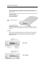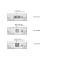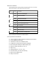
1
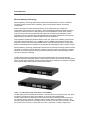
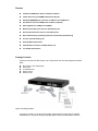
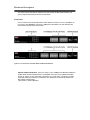
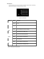
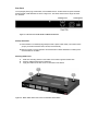
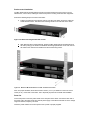
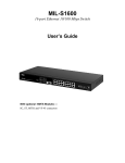
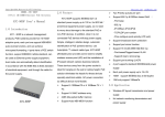
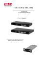
MIL-S2400 & MIL-S1600
Fast Ethernet Switch
16 or 24 10/100 Mbps auto-sensing ports
with optional 1 port 100Mbps Fiber Module
User Guide
With Optional Fiber 100BASE-TX Extension
100Base-FX with Module with SC/ST/MT-RJ/ VF-45
Multi-mode and Single-mode
Regulatory Approval
- FCC Class A
- UL 1950
- CSA C22.2 No. 950
- EN60950
- CE
- EN55022 Class A
- EN55024
Canadian EMI Notice
This Class A digital apparatus meets all the requirements of the Canadian Interference-Causing Equipment
Regulations.
Cet appareil numerique de la classe A respecte toutes les exigences du Reglement sur le materiel brouilleur du
Canada.
European Notice
Products with the CE Marking comply with both the EMC Directive (89/336/EEC) and the Low Voltage Directive
(73/23/EEC) issued by the Commission of the European Community Compliance with these directives imply
conformity to the following European Norms:
-
EN55022 (CISPR 22) - Radio Frequency Interference
EN61000-X - Electromagnetic Immunity
EN60950 (IEC950) - Product Safety
Five-Year Limited Warranty
MiLAN Technology warrants to the original consumer or purchaser that each of it's products, and
all components thereof, will be free from defects in material and/or workmanship for a
period of five years from the original factory shipment date. Any warranty hereunder is
extended to theoriginal consumer or purchaser and is not assignable.
MiLAN Technology makes no express or implied warranties including, but not limited to, any
implied warranty of merchantability or fitness for a particular purpose, except as expressly set
forth in this warranty. In no event shall MiLAN Technology be liable for incidental or
consequential damages, costs, or expenses arising out of or in connection with the
performance of the product delivered hereunder. MiLAN Technology will in no case cover damages
arising out of the product being used in a negligent fashion or manner.
Trademarks
© 2000 MiLAN, the MiLAN logo and MiLAN Technology are either trademarks or registered
trademarks of Digi International, Inc. in the United States and/or other countries. All other
trademarks are the property of their respective holders.
To Contact MiLAN Technology
For prompt response when calling for service information, have the following information ready:
- Product serial number and revision
- Date of purchase
- Vendor or place of purchase
You can reach MiLAN Technology technical support at:
E-mail: [email protected]
Telephone: +1.408.744.2751
Fax: +1.408.744.2771
MiLAN Technology
1299 Orleans Drive
Sunnyvale, CA 94089-1138
United States of America
Telephone: +1.408.744.2775
Fax: +1.408.744.2793
http://www.milan.com
info @ milan.com
© Copyright 2001 MiLAN Technology
P/N: 90000372_A
Contents
1. Introduction…….…………….…………….……….………….……
1
Features …………………………………………..…..…….…
2
Package Contents ………………………..…..……….………
3
Ethernet Switching Technology ………………….……………
4
2. Hardware Description ………………..….…..…...………….…………
6
Front Panel ………………………………………...…...…………
6
LED Indicators …………………………………………………….
7
Real Panel …………………………………………….…………..
8
Desktop Installation ……………………….…….………………..
9
Rack-mounted Installation …...…………….……………………
9
3. Optional Fiber Modules ………….…..……….…………….…………
12
Front Panel …………………………………...…...….….…..…
12
Features/ Specifications …………….………………..….…….
15
Installing 100Base-FX Module ………………………………………. 15
4. Network Application .…………………….…………… ……………
17
Small Workgroup ………………………………….......……..…
17
Segment Bridge …………….……………..…………..….…….
18
5.Troubleshooting .…………………………………..…. ………………
20
Incorrect connections ...…………………………………………
20
Diagnosing LED Indicators ………………………..….………..
21
6. Technical Specification .…………………….…....…. …………………
22
Introduction
Ethernet Switching Technology
Ethernet Switching Technology dramatically increases the total bandwidth of a network, eliminates
congestion problems inherent with ( CSMA/CD ) protocol, which greatly reduces unnecessary
transmissions.
Switch Technology has revolutionized networking. First, by allowing two-way, simultaneous
transmissions over the same port ( Full-duplex ), which essentially doubled the bandwidth. Second, by
reducing the collision domain to a single switch-port, which eliminated the need for carrier sensing.
Third, by using the store-and-forward technology’s approach of inspecting each packet to prevent
transmitting corrupt or redundant data, switching eliminates unnecessary transmission. By employing
address-learning, the switch only transfers data to the port it is destined for.
Auto-negotiation regulates the speed and duplex of each port, based on the capability of both devices.
Flow-control allows transmission from a 100Mbps node to a 10Mbps node without loss of data. Autonegotiation and flow-control may require disablement for some networking operations involves legacy
equipment. Disabling the auto-negotiation is accomplished by configuring the speed or duplex of a port.
Ethernet Switching Technology supplies higher performance at costs lower than legacy solutions. Wider
bandwidth, no congestion, and the reduction in traffic are the many reasons why switching is replacing
expensive routers and inefficient hubs for the ultimate networking solution. Switching brings a whole
new way of thinking to networking.
The MIL-S2400 and MIL-S1600 Switches are multi-port Switches that can be used to build highperformance switched workgroup networks. These switches are store-and-forward devices that offer low
latency for high-speed networking. They are targeted at workgroup, department or backbone computing
environment at SME ( small, medium enterprise ) businesses.
Figure 1-1. The MIL-S2400 and MIL-S1600 Switch ( Auto MDI/MDIX )
The MIL-S2400 and MIL-S1600 Switches feature a “store-and-forward “ switching scheme. This allows
the switch to auto-learn and store source address on an 4K-entry MAC address table.
The MIL-S2400 and MIL-S1600 Switches have 16/24 auto-sensing 10/100Base-TX RJ-45 ports plus
one extension slot for ( Optional ) 100Base-FX fiber module enables long-distance connection. The
optional modules support MT-RJ, SC single-mode, ST, MT-RJ, VF-45 multi-mode connectors. The fiber
port can be used to connect to a remote side up to 2 Km ( multi-mode ) or 60Km ( single-mode ).
Features
n
Conforms to IEEE 802.3, 802.3u, and 802.3x standard
n
16/24x auto-sensing 10/100Mbps Ethernet RJ-45 ports
n
Automatic MDI/MDIX ports crossover for 10Base-T and 100Base-TX
n
One Extension Slot for 100Mbps Fiber modules ( Optional )
n
Auto-negotiation for 10Mbps and 100Mbps
n
Back-Pressure-Base flow control on Half-duplex ports
n
Pause-Frame-Base flow control on Full-duplex ports
n
Store-and-forwarding switching architecture for abnormal packet filtering
n
Full wire speed forwarding rate
n
4K-entry MAC address table
n
LED-indicators for Power, 10/100M, LK/ACT, Full
n
19” Standard Rack-mount
Package Contents
Unpack the contents of the MIL-S2400 or MIL-S1600 Switch and verify them against the checklist
below.
n
n
n
n
n
MIL-S2400 or MIL-S1600 Switch
Power Cord
Four Rubber Feet
Rack mount kit
Warranty Card
Figure 1-2. Package Contents
Compare the contents of your MIL-S2400 and MIL-S1600 Switches package with the standard
checklist above. If any item is missing or damaged, please contact your local dealer for service.
Hardware Description
This Section mainly describes the hardware of the MIL-S2400 and MIL-S1600 Switches, and
gives a physical and functional overview of each Switch.
Front Panel
The Front Panel of the MIL-S2400 and MIL-S1600 Switches consists of 16 or 24 10/100Base-TX
RJ-45 ports ( Auto MDI/MDIX ) and slot for 100Base-FX Fiber Module. The LED Indicators are
also located on the front panel of the Switch.
Figure 2-1. The Front panel of the MIL-S2400 and MIL-S1600 Switches
Optional 100Base-FX Modules: There are 5 types of 1-port 100Mbps Fiber Modules available for
the MIL-S2400 and MIL-S1600 Switches. The available connectors on the 100Base-FX Module
are SC, ST, MT-RJ, VF-45 ( multi-mode ) and MT-RJ, SC ( single-mode ). The distance for multimode fiber cabling can extend up to 2 kilometers. The distance for SC and MT-RJ single-mode
fiber cabling is 60 kilometers.
( See Section 3. Optional Modules )
LED Indicators
The LED Indicators gives a real-time information of systematic operation status. The following
table provides descriptions of LED status and their meaning.
Figure 2-2. LED Indicators
LED
Status
Green
Off
Green
Description
Power On
Off
The port is operating at the speed of 100Mbps.
100M
Off
LK/ACT
No device attached or in 10Mbps mode
Green
The port is active with device(s) attached
Blinks
The port is receiving or transmitting data.
Off
Yellow
No device attached.
The port is operating in full-duplex mode.
Full
Off
No device attached or in half-duplex mode .
Table 2-1. The Description of LED Indicators
Rear Panel
The 3-pronged power plug, On/Off switch, and ventilation fan are located at the rear panel of the MILS2400 and MIL-S1600 Switches as shown in Figure 2-2. The Switch will work in the range 100-240V
AC, 50-60Hz.
Figure 2-3. The Rear Panel of MIL-S2400 and MIL-S1600 Switches
Desktop Installation
A. Set the Switch on a sufficiently large flat space with a power outlet nearby. The surface where
you put your Switch should be clean, smooth, level and sturdy.
B. Make sure there is enough clearance around the Switch to allow attachment of cables, power
cord and allow air circulation.
Attaching Rubber Feet
A.
B.
C.
Make sure mounting surface on the bottom of the Switch is grease and dust free.
Remove adhesive backing from rubber feet.
Apply the rubber feet to each corner on the bottom of the Switch.
Figure 2-4. Attach rubber feet to each corner on the bottom of the Switch
Rack-mounted Installation
The MIL-S2400 and MIL-S1600 switches includes a rack-mounted kit and can be mount in an EIA
standard size, 19-inch Rack, enabling the switch to be placed in a wiring closet with other equipment.
Perform the following steps to rack mount the switch:
A.
Position one bracket to align with the holes on one side of the switch and secure it with the
smaller bracket screws. Then attach the remaining bracket to the other side of the switch.
Figure 2-4. Attach mounting brackets with screws
B.
After attaching both mounting brackets, position the MIL-S2400 and MIL-S1600 Switches in
the rack by lining up the holes in the brackets with the appropriate holes on the rack. Secure
the switch to the rack with a screwdriver and the rack-mounting screws.
Figure 2-5. Mount the MIL-S1600 Switch in an EIA standard 19-inch Rack
Note: For proper ventilation, allow about at least 4 inches ( 10 cm ) of clearance on the front and 3.4
inches ( 8 cm ) on the back of the switch. This is especially important for enclosed rack installation.
Power On
Connect the power cord to the power socket on the rear panel of the switch. Connect the other end of
the power cord to the power outlet. The internal power supply of the switch works with AC in the voltage
range 100-240VAC, frequency 50~60Hz.
Check the power indicator on the front panel to see if power is properly supplied.
Optional Fiber Modules
This section introduces the optional 100Base-FX Modules which can be installed on the front
panel of the MIL-S2400 and MIL-S1600 Switches. Each optional 100Base-FX Module has a oneport fiber connector.
The 100Base-FX Modules are designed to extend the distance between switch and other devices.
The maximum distance
connected by optical fiber is up
to 2 Km ( multi-mode fiber ) or
60 Km ( single-mode fiber ).
Figure 3-1. The optional 100Base-FX
Module
You can regard this fiber port
as backbone in the networking
infrastructure. There are four types of fiber port connectors available including ST, SC, MT-RJ,
VF-45 multi-mode and SC and MT-RJ single-mode connectors. The following is the introduction
about them.
Front Panel
The Front Panels of the 100Base-FX Modules consist of four LED-indicators, two thumbscrews,
DIP-switch, and one fiber port. An example of each of the Front Panels of the 100Base-FX
Modules are illustrated. Model number and serial number can be found on a label on the
underside of the module.
MIL-L1624SC
MIL-L1624SC-60
MIL-S2416ST
MIL-S2416MT
MIL-S2416VF
LED Indicators of 100base-FX
The LED-Indicators provide a real-time information of systematic operation status. The following
table provides descriptions of LED Indicators status and their meaning.
LED
Status
Blinks
Off
Blinks
Description
This fiber port is transmitting data.
No data is be transmitted.
This fiber port is receiving data.
RX
Off
Yellow
No data is being received.
The port is connecting with the device.
Link
Off
FD/COL
No device attached.
Yellow
The port is operating in Full-duplex mode.
Blinks
Collision of is occuring
Off
No device attached or in half-duplex mode .
Table 3-1. The Description of LED-Indicators on 100Base-FX Modules
Features / Specifications of the 100Base-FX
n
Conforms to IEEE 802.3u 100Base-FX & 802.3x Full Duplex Flow Control standard
n
One-port 100Mbps optical fiber module
n
LED-indicators for TX, RX, Link, and FDX/COL (4 LEDs)
n
One DIP-switch to select fiber port for Full-duplex or Half-duplex.
n
Max. Forwarding Rate: 148810 pps for 100Base-FX (Wire speed)
n
Dimensions: 102mmx 71mmx 24mm ( 4” x 2.8” x 1” )
n
Weight : 60 ±5g
n
Operating Temperature : 0 ~ 45 C (31 ~ 113 F)
n
Environment Humility : 10% ~90% ( Non-condensing )
n
EMI : FCC Class A, CISPR 22 Class A
n
Safety: UL, cUL and TUV
Installing 100Base-FX Module
The optional 100Base-FX Modules are designed to be inserted in the extension slot. Before
installation, ensure that the power is disconnected. The module is NOT hot-swappable. Follow the
steps below to install the optional 100Base-FX Module:
1.
Power the MIL-S2400 and MIL-S1600 Switches OFF before installing the 100Base-FX
Module.
2.
Unscrew the thumbscrews on the blank bracket. Remove the blank bracket and set aside, but
do not discard it. Replace the blank bracket if you should remove the fiber module.
3.
Install the new 100Base-FX Module by inserting it into the guides and sliding it in until it stops
( See Figure 3-7 ). Press it firmly until you feel the module snap into place. Never force, twist
or bend the 100Base-FX Module.
Figure 3-7. Install the 100Base-FX Module by inserting it into the guides and sliding it in until it stops
4.
Gently push the thumbscrews in and turn clockwise to tighten. Do not over tighten the
thumbscrews.
5.
Power MIL-S2400 and MIL-S1600 Switches ON, and the Switch will automatically detect the
100Base-FX Module. Plug the fiber cable connector into the 100Base-FX Module. Check the
LEDs to verify that if there is a link and proper connection.
Troubleshooting
This section is intended to help you solve the most common problems on the MIL-S2400 and MILS1600 Switches.
n
Faulty or loose cables
Look for loose or obviously faulty connections. If they appear to be OK, make sure the connections are
snug. IF that does not correct the problem, try a different cable.
n
Non-standard cables
Non-standard and miswired cables may cause numerous network collisions and other network problem,
and can seriously impair network performance. A category 5 cable tester is a recommended tool for
every 100Base-TX network installation.
n
Improper Network Topologies
It is important to make sure that you have a valid network topology. You should make sure that your
network topology contains no data path loops. Between any two ends nodes, there should be only one
active cabling path at any time. Data path loops will cause broadcast storms that will severely impact
your network performance.
Diagnosing LED Indicators
The Switch can be easily monitored through panel indicators to assist in identifying problems,
which describes common problems you may encounter and where you can find possible solutions.
If the power indicator does turn on when the power cord is plugged in, you may have a problem
with power outlet, or power cord. However, if the Switch powers off after running for a while, check
for loose power connections, power losses or surges at power outlet. If you still cannot resolve the
problem, contact your local dealer for assistance.
n
Cabling
A.
RJ-45 ports: Use unshielded twisted-pair (UTP) or shield twisted-pair ( STP ) cable for RJ45 connections: 100O Category 3, 4 or 5 cable for 10Mbps connections or 100O Category 5
cable for 100Mbps connections. Also be sure that the length of any twisted-pair connection
does not exceed 100 meters ( 328 feet ).
B.
100Base-FX fiber port: Fiber multi-mode connector type must use 50,62.5/125 um multimode fiber cable. You can connect two devices over a 2-kilometer distance. However, Fiber
single-mode connector type must use 9/125 um single- mode fiber cable. You can connect
two devices over a 60- kilometer distance in full duplex operation.
Technical Specification
This section provides the specifications for the MIL-S2400 and MIL-S1600 Switches.
Specifications
Standard
IEEE 802.3 10Base-T Ethernet,
IEEE 802.3u 100Base-TX/FX Fast Ethernet
Protocol
CSMA/CD
Max Forwarding Rate and
Max Filtering Rate
14,880 pps per Ethernet port,
148,800 pps per Fast Ethernet port
LED Indicators
10/100 UTP Port: 100M, LK/ACT, Full ( 3 LEDs)
100M Fiber Port: TX, RX, Link, FD/COL ( 4 LEDs)
Per Unit: Power
Copper Network Cables
10Base-T: 2-pair UTP/STP Cat. 3, 4, 5 cable
EIA/TIA-568 100-ohm (100m )
100Base-TX: 2-pair UTP/STP Cat. 5 cable
EIA/TIA-568 100-ohm (100m )
Fiber Link Max. Distance
ST, SC, MT-RJ, VF-45 Multi-mode:
Half-duplex- 412m , Full-duplex- 2Km
MT-RJ/SC Single-mode:
Half-duplex- 412m , Full-duplex- 60Km
Dimensions
MIL-S1600 +1Fiber Module Switch :
440mm x 160mm x 44mm ( L x W x H ) 17.4” x 6.3” x 1.75”
MIL-S2400 +1Fiber Module Switch :
440mm x 160mm x 44mm ( L x W x H ) .95”
100Base-FX Module : 102mm x 71mm x 24mm ( L x W x H )
Weight
16TP+1Fiber Module Switch : 2.2 Kg 4.85 lbs
24TP+1Fiber Module Switch : 2.3 K 5 lbs
100Base-FX Module : 60 ±5g .14 lbs
Storage Temp.
-40ºC to 70ºC ( -40ºF to 158ºF)
Operational Temp.
0ºC to 45ºC ( 32ºF to 113ºF )
Operational Humidity
10% to 90% (Non-condensing)
External Power
100-240V AC, 50-60Hz
Output rate: +5V/2A, +3.3V/8A
Power Consumption
MIL-S1600 :10 Watts ( Max ) MIL-S2400 :13 Watts ( Max )
EMI
FCC Class A, CISPR 22 Class A, CE Mark
Safety
UL, cUL and TUV
P/N: 90000372_A