1
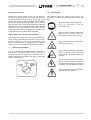
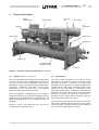
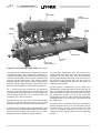
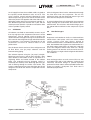
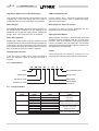
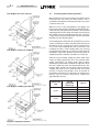
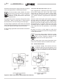
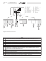
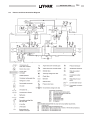
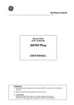
035L02381-GB0
2.3
Motor
The compressor motor is an open drip-proof, squirrel
cage induction type. The motor has a D-flange and cast
iron adaptor mounted rigidly to the compressor for
accurate alignment of motor and compressor shafts.
The motor drive shaft is connected to the compressor
shaft with a flexible disc coupling. Coupling has all metal
construction with no wearing parts to assure long life,
and no lubrication requirements to provide low
maintenance.
On units supplied without the optional solid state starter,
for use with a remote electromechanical starter, a large
steel motor terminal box with gasketed front access
cover is provided for field connected conduit. Six
terminals are provided in the terminal box, two for each
motor winding, allowing connection for star-delta (S/D)
or direct-on-line (DOL) starting. Jumpers are provided
for direct-on-line connection. Motor terminal lugs are not
provided. Overload/over-current transformers are fitted
as standard.
2.4
Oil Separator
The oil separator removes the oil that was injected into
the compressor. The separator is a horizontal three
stage design without moving parts.
Figure 2.3 Oil Seperator
2- 3
In the first stage of oil separation, high velocity oil and
refrigerant gas in the compressor discharge line under
goes a rapid reduction in velocity as it enters the large
diameter oil separator. Most of the oil drops out of the
refrigerant gas stream due to the reduction in velocity.
The oil falls by gravity into the oil reservoir located in the
bottom of the oil separator.
The second stage of oil separation is accomplished by
directing the refrigerant gas through mesh pads that
have an extended surface area. Smaller liquid oil
droplets are collected on the extended surface area of
the wire mesh pads where the oil falls by gravity into the
oil reservoir.
The third and final stage of oil separation is achieved in
the oil coalescing element section of the oil separator.
The oil mixed with the refrigerant entering the coalescer
element is a very fine aerosol mist. These small aerosol
mist particles wet the coalescer element media and form
larger oil droplets which fall by gravity to the bottom of
the coalescer element section. The oil collected in the
coalescer section is drained from the oil separator with a
small amount of refrigerant gas. This provides the high
pressure “gas drive” for the eductors to return oil from
the evaporator.
The oil separator has a design working pressure (DWP)
of 20.6 bar. The separator is fitted with a single or dual
pressure relief device (depending on safety code
requirements) set at 20 bar.