1
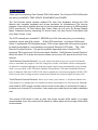
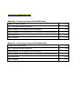
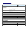
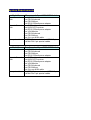
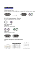
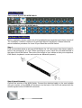
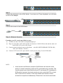
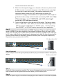
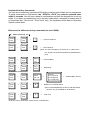
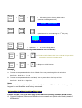
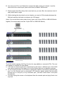
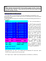
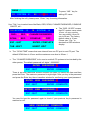
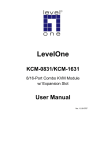
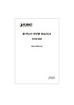
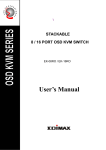
TWO-CONSOLE
(One Local , One CAT5 Remote)
8 port / 16 port
19” RACK MOUNTABLE
PS/2 KVM SWITCH
USER’S MANUAL
Rev 1.0
TABLE OF CONTENTS
INTRODUCTION……………….……………………………………..1
FEATURES…………...……………………………………………….2
PACKAGE CONTENTS……………...…………..……………………3
TECHNICAL SPECIFICATIONS………..…………………………….4
SYSTEM REQUIREMENT…………………………………………..5
CABLE DIAGRAMS………………………………………………….5
PRODUCT DETAILS…………………………………………………6
HARDWARE INSTALLATION………………………………………6
USAGE…………………………………………………………………7
DAISY CHAIN CONNECTION DIAGRAM…………………………10
HOT PLUG……………………………………………………………11
ON SCREEN DISPLAY OPERATION……………………………11
TROUBLESHOOTING………………………..…………………….14
CERTIFICATES……………………………………………………..14
Introduction
Thank you for purchasing Two-Console PS/2 KVM switch. Two-Console PS/2 KVM switch
can save your MONEY, TIME, SPACE, EQUIPMENT and POWER.
The Two-Console switch controls multiple PCs from One Keyboard, Mouse and VGA
Monitor with complete keyboard and mouse emulation for simultaneous PCs boot-up
process. It has various features such as one local console port and one up to 500-feet away
CAT5 console port, 19” Rack Mount Size, Daisy Chain up to 8 units, On Screen Display
Menu, Password security, searching PC server name, Hot key Control, Push Button and
Auto Scan Control. It has
The CAT5 console port extends PC, SERVER up to 500 feet away from your controlling
keyboard, mouse and VGA monitor. “ KVM CAT5 transmitter “ is built-into KVM switch
inside. It synthesizes PS/2 keyboard signal , PS/2 mouse signal and VGA monitor signal to
be easily transmitted to a long distance over popular Ethernet CAT5 cable. The “ Cat5
Remote Console Receiver “ is to get the synthetic signal and return it back to PS/2
keyboard, PS/2 mouse and VGA monitor signal. Besides, “Cat5 Remote Console Receiver”
allows the other PC to share this remote console via one extra PC port which is built in the
receiver.
“Cat5 Remote Console Receiver” is a good solution for those noisy server room environment
where is unsuitable for people to work for a long time, besides, it facilitates effective management
on dispersive computers through one dedicated central control room, demonstration room, meeting
room, or at your desk. CAT5 STP cable (Shielded Twisted Pair)/ UTP cable (Unshielded Twisted
Pair) or enhanced cable like CAT5E/CAT6 cable is applied to LAN network popularly. KVM-CAT5
Extra uses the same existing network construction to transfer local console signal to remote side.
“Cat5 Remote Console Receiver” allows you to move your console, i.e. Keyboard, Mouse and
VGA monitor, to a suitable place for centralized control conveniently over LAN network. You just
need install a CAT5 remote console receiver at the remote side you would like to locate or
to share one of remote PC’s consoles. It also saves your cable layout and cable installation
cost.
Two-console KVM switch is able to work with single console KVM switch. It is highly
recommended to put two-console KVM switch at master bank and the single KVM switch
at slave banks.
Features
z
8/16 port Two-Console PS/2 KVM switch is 19” rack mount size design.
z
Support one local console and one CAT5 remote console up to 500 feet away from
KVM switch.
z
Support Microsoft Intellimouse, Microsoft Intellimouse Explorer, Logitech Net Mouse or
the other fully compatible MS mice.
z
Support DOS, Win3.X, Win95/98/98SE/2000/ME/XP, WinNT, Netware, Unix, Linux
z
Support iMAC, Power MAC and Sun Microsystems with USB port (Need work with
USB-PS/2 adapter)
z
Hot Plug - Add PCs or Remove Connected PCs for Maintenance without Powering off
the KVM switch or PCs.
z
Very High Video Quality - Up To 1920X1440, Bandwidth: 200MHz
z
No Software Required - easy PC selection via On Screen Display Menu, Push Buttons,
and Hot Keys
z
Support eight-character password protection and PC server name searching
z
Auto Scan Mode for monitoring PCs with flexible Scan time from 5~99 seconds
z
Keyboard status restored when switching PCs
z
LED Display for easy status monitoring
z
Buzzer sound for switching port confirmation.
z
Built-in one extra daisy chain port without wasting any PC port
z
No DIP switch setting needed and auto detect daisy chain bank
PACKAGE CONTENTS
Model No.: Two-console 8 port PS/2 KVM Switch
8 port PS/2 KVM Switch
1 PC
CAT 5 Remote Console Receiver
1 PC
Power Adapter DC9V,500mA (for KVM Switch)
1 PC
Power Adapter DC9V,500mA (for CAT5 Remote Console Receiver)
1 PC
Rack Mount Kit
User’s manual
1 SET
1 PC
Model No.: Two-console 16 port PS/2 KVM Switch
16 port PS/2 KVM Switch
1 PC
CAT 5 Remote Console Receiver
1 PC
Power Adapter DC9V,500mA (for KVM Switch)
1 PC
Power Adapter DC9V,500mA (for CAT5 Remote Console Receiver)
1 PC
Rack Mount Kit
User’s manual
1 SET
1 PC
Technical Specifications
Model No.
PC Port
Console Port
PC Port Connector
(All Female Types)
Console Port Connector
(All Female Types)
Daisy Chain Port Connector
(All Female Type)
PC selection
PC Port LED
Bank 7 segment LED
On Screen Display Control
Scan Intervals
Keyboard Emulation
Mouse Emulation
VGA Resolution
Bandwidth
Daisy Chain MAX Level
MAX PC Connection
Housing (KVM Switch)
Two-console 8 port PS/2 KVM Switch Two-console 16 port PS/2 KVM
Switch
9 (8 local and 1 remote)
17 (16 local and 1 remote)
2 (1 local and 1 remote)
2 (1 local and 1 remote)
VGA HDDB 15pin ( shared with PS/2 keyboard and Mouse )
Local Console: PS/2 Keyboard Mini Din 6 pin
PS/2 Mouse Mini Din 6 pin
VGA HDDB 15pin
Remote Console: RJ-45 8P8C
PS/2 Keyboard mini Din 6 pin
PS/2 Mouse Mini Din 6 pin
VGA HDDB 15pin
On Screen Display Menu, Hot Key, Push Button
16
32
1
Yes
5~99 Sec.
PS/2
PS/2
1920X1440
200MHz
8 levels
121 (120 local and 1 remote)
129 (128 local and 1 remote)
Metal
Housing (CAT5 Receiver)
Plastic
KVM Switch Power Adapter DC 9V, 500mA
Cat5 Remote Console
DC 9V, 500mA
Receiver Power Adapter
0~50℃
Operation Temperature
-20 ~ 60℃
Storage Temperature
Humidity
0~95%, Non-Condensing
Size
19” Rack Mount / 1RU
Weight (g) (KVM Switch)
2010
Weight (g) (CAT5 Receiver)
120
Dimension (cm) (KVM Switch)
41(L) X 16.4(W) X 4.5(H)
Dimension (cm) (CAT5
11.15(L)x7.5(W)x3.95(H)
Receiver)
19” Rack Mount / 1RU
2220
120
41(L) X 16.4(W) X 4.5(H)
11.15(L)x7.5(W)x3.95(H)
System Requirements
Model No.
Local Console
side
Two-console 8 port PS/2 KVM Switch
One VGA Monitor
One PS/2 Keyboard
One PS/2 Mouse
One DC9V 500mA power adapter
Remote Console One CAT5 cable
side
One KVM CAT5 receiver
One DC9V 500mA power adapter
One VGA Monitor
One PS/2 Keyboard
One PS/2 Mouse
One 3-in-one KVM cable
Computer side
8 HDDB 15 pin male to one HDDB 15 pin
and Mini Din 6 pin special cables
Model No.
Console side
Two-Console 16 port PS/2 KVM Switch
One VGA Monitor
One PS/2 Keyboard
One PS/2 Mouse
One DC9V 500mA power adapter
Remote Console One CAT5 cable
side
One KVM CAT5 receiver
One DC9V 500mA power adapter
One VGA Monitor
One PS/2 Keyboard
One PS/2 Mouse
One 3-in-one KVM cable
Computer side
16 HDDB 15 pin male to one HDDB 15 pin
and Mini Din 6 pin special cables
Cable Diagrams
PC Port Special Cable:
HDDB15 pin male to one HDDB 15 pin male and Mini Din 6 pin special cables
------------Æ
AT to PS/2 keyboard adapter: (Optional)
Din 5 pin Male to Mini Din 6 pin Female
Daisy Chain Cable:
PS/2 Cable:
Mini Din 6 pin Male to Male
VGA Cable:
HDDB15 pin Male to Male
CAT5/5E/6 Straight Through UTP/STP Cable:
8P8C
Product Details
Two-console 8 port PS/2 KVM Switch:
Two-console 16 port PS/2 KVM Switch:
Hardware Installation
Before installation, please make sure all of peripherals and computers have been turned off.
The installation of below is based on 8 port-Rack Mount KVM Switch. Please follow the
same installation procedure for 4 and 16 port Rack Mount KVM Switch.
Step 1
Find a convenient place to put your KVM Switch. Its 19” rack mount form factor makes it
ideal to be mounted on 19” rack. When mounting to a rack, attach the included brackets to
the sides of the KVM Switch. Take note of the length of your cables so that your computers,
KVM Switch, keyboard, mouse and monitor are distanced properly.
Step 2 (Local Console)
Connect the monitor to the KVM Switch. Connect the attached cable, or the one included
with your monitor, to the HDDB-15 female port on the back of the KVM unit marked with the
monitor symbol at the CONSOLE connector.
Step 3
Connect the keyboard to the KVM Switch. If you have an AT type keyboard, you will need
an AT to PS/2 adapter.
Step 4
Connect the mouse to the KVM Switch.
Step 4-1 (Remote Console)
Extending your PC console up to 500 feet away:
(1) To make sure the CAT5 cable is straight through type.
(2) Plug one end of the CAT5 cable into RJ-45 connector of PS/2 KVM switch and the other end
into KVM CAT5 receiver RJ-45 port.
(3) Connect remote keyboard, mouse and monitor with PS/2-EXTENDER-RECEIVER “KB“,
“MS“ and “Monitor” interface.
(4) Connect CAT5 receiver PC port with PC console port by using 3-in-one KVM cable.
NOTE:
1. Local console and Remote console of KVM Switch will have the same
priority to control computer, just like a PC connected to two consoles. The
remote console can control both the local PC and remote PC connected to
KVM switch; however, the local console can only control the PCs on local
side. There will be a conflict, if the local console and remote console
access the computer simultaneously. Please don’t use local console and
remote console at the same time.
2. When the video signal is foggy or un-cleared on the screen, please check
if VGA connector is connected properly, or the VGA resolution is too high
for the length of cable being used. If the problem happened at VGA
resolution, please shorten the CAT5 cable length or reduce VGA
resolution. It is highly recommended to use “optimal CAT5 cable length “to
get the best video quality and don’t waste unnecessary CAT5 cable. High
VGA resolution is up to 1280X1024 and CAT5 cable length
could up to 500 feet approximately.
3. There is a Dip Switch on the rear site of KVM switch. The factory default
value is “ OFF/ OFF “ state. When you use the CAT5 cable length is over
300 feet, please set DIP Switch to “ ON/ON “ state. The other setting
likes “ON/OFF” or “OFF/ON” state is reserved for future application.
Step 5
PC port connectors of the KVM switch are HDDB-15 pin type. Plug one end of the calbe
which is HDDB-15 pin male connector to the selected computer port on the rear of KVM
switch unit. The other end of cable which have three connectors: a HDDB-15 pin male type
for PC video, a Mini Din 6 pin female type for keyboard and a Mini Din 6 pin female type for
mouse, will be attached to keyboard, mouse and monitor ports of computer respectively.
Repeat the same procedure to all of PCs.
The Rear Side of PC
Step 6 (Optional)
If your computer has an AT type keyboard port (Din 5 pin), you will need a PS/2 to AT keyboard
adapter.
The Rear side of PC
Step 7
Check all of the connections carefully. The colors of keyboard and mouse connectors will
help to make sure the keyboard and mouse cables go to the correct ports.
Step 8
Attach the power supply to the KVM unit and plug the other end into an electrical receptacle.
Now you will see the LED for Port 1 light up, and you will hear a beep. Switch on your
monitor.
NOTE:
It is suggested to plug in power adapter, although the PCs connected to KVM Switch are
able to support enough power to the stand alone switch. However, KVM Switch will need a
power adapter to daisy chain more banks and if you forget to plug in power adapter on the
status of daisy chain, it may cause unexpected consequence.
Usage
The power on state of two-console 4/8/16 port KVM switch:
When you power on KVM switch, it will ask you the password, the default password value
is eight zero –“ 00000000 “. Please key in eight zero and enter the same value at re-type
field.
Note: Don’t change the password and keep default eight zero (00000000) value until you
are familiar with the operation of OSD menu. If unfortunately, you forget the password that
has been set, you will need send it back to your distributor to maintain the password.
The Membrane Buttons
:
Pressing the individual button cyclically through all the ports or the respective button to get
PC port you want. For 16 port KVM Switch, please press “↵” and individual button
simultaneously in order to select the port 9 to port 16.
PC port LED Indicator :
When the selected PC port is disconnected to PC or PC connected is shut down, the selected PC
port LED will flash. When you select one of the PC ports that is powered on, the selected PC port
LED is lit.
7-Segment BANK LED Indicator
To view the next bank KVM switch, please press “ BANK “ push button cyclically for the
destination bank. The LED indicator for bank no. will be changed from bank 1 to the
maximum daisy chain level and then to press “ BANK “ push button once back to the bank
1.
Bank 1
Bank 2
Bank 3
MAX. BANK
Reset Button (
(“ Bank ” button) and
(“ PC 8 ” button ) ):
To reset the KVM switch , please press both “PC8” button and “bank” button of master bank
simultaneously. This reset action will not only return KVM switch back to initial state, i.e.
Check the password, but also re-check all of slave banks which connected to master KVM
Switch.
If you add a new KVM Switch as a slave bank, please use reset button of master KVM
Switch to automatically assign a new ID to the new KVM switch. You can view this new
slave bank via OSD menu. The PC ports of KVM Switch will not be reset by this reset
command.
Keyboard Hot Key Commands:
You can also conveniently command KVM switch to switch ports simple via key sequences.
To send commands to KVM switch, the “SCROLL LOCK” key must be pressed twice
within 2 seconds. You will hear a beep for confirmation and then the keyboard is in hot key
mode. If you have not pressed any key in hot key mode within 2 seconds (It means there is
no keystroke after “Scroll Lock” “Scroll Lock” key ), the keyboard will be back to Operation
System control state.
Below are the different hot key commands (for local KVM):
within 2 seconds
Scroll
Lock
+
Scroll
Lock
+
↑
=
Previous Channel
Scroll
Lock
+
Scroll
Lock
+
↓
=
Next Channel
(Note: You also could press “up arrow key” or “down arrow
key” longer time to speed up selecting the destination
port)
Scroll
Lock
+
Scroll
Lock
+
Page
Up
=
Previous Bank
Scroll
Lock
+
Scroll
Lock
+
Page
Down
=
Next Bank
To select PC port:
Scroll
Lock
Scroll
Lock
+
+
Scroll
Lock
Scroll
Lock
+
+
Bank
No 1~8
B
+
=
Port No.
01~04 (4 port)
01~08 (8 port)
01~16 (16 port)
= Selected Bank and PC
Beeper on local KVM Switch
(Note: The default Beeper function is ON and beeper
control is only for available for Scan Mode )
Scroll
Lock
+
Scroll
Lock
+
S
=
Auto Scan
To get out of Auto Scan Mode, Press any key or SPACE bar.
Scroll
Lock
+
Scroll
Lock
+
R
=
OSD setting back to factory default value
(Note: Not including password)
ROM
Scroll
Lock
+
Scroll
Lock
+
F
=
REFLASH
Search the same PC name
(Note: Search PC name starting from 1st PC port)
FIND:█
Scroll
Lock
+
Scroll
Lock
+ Space bar =
On Screen Display Menu
Below are the different hot key commands (for CAT5 remote):
Scroll
Lock
+
Scroll
Lock
+
Scroll
Lock
+
Scroll
Lock
+
C
= To select CAT5 Remote PC Port and local PC port which
connected to receiver by toggle control
Q
= Beeper on CAT5 Receiver
Example:
A. To access a computer attached to Port 4 of Bank 3. You can press through hot key as below:
Scroll lock + Scroll lock + 3 + 04
B. To access a computer attached to next Bank, You can press through hot key as below:
Scroll lock + Scroll lock + Page Down
Note:
Use numeric keys on the keyboard to select Bank no. and Port no. Numeric keys on the
keypad are not available as a hot key command.
Daisy Chain Connection Diagram
Please use the 3 feet 3-in-one daisy chain Cable Kit to daisy chain the KVM Switch.
A. Connect Keyboard, Mouse and Monitor to the console port (white color block) of bank 1
KVM switch.
B. Use one end of 3-in-one Cable Kit to connect the daisy chain port of bank 1 and the
other end to the console port (white color block) of bank 2 KVM switch.
C. Please repeat item B to daisy chain more bank as you want. But, the maximum level of
daisy chain bank is eight.
D. While chaining the slave bank up to six banks, you need a VGA extender between the
fifth bank and the sixth bank to enhance the VGA signal.
(Note: If you would like to daisy chain 4 port, 8 port, and 16 port PS/2 or USB KVM Switch
together, the master bank must be 16 port PS/2 or USB KVM Switch)
Hot Plug
The KVM Switch supports “Hot Plug“ function for easy addition or removal of PCs. The user
can arrange or maintain PCs as follows:
a. A PC can be disconnected and reconnected to the same or different port of the KVM
unit without powering off as long as it is not the Daisy-chain port or pass through port.
b. To use hot plug function on PC which is powered on before connected to pass through
port, (i.e. the console port is connected to PC directly), please switch from the pass
through port to next port (or say emulation port ) and then switch back to the pass
through port.
c. You may unplug the mouse or the keyboard from the console port and plug it back in at
any time.
NOTE:
Some O.S. (Operation Systems) like SCO Unix are unable to support “ Hot Plug ” function. If
you apply “Hot Plug” to this kind of O.S., it will cause unpredictable behavior or shut down
the PC. Before using “ Hot Plug ” , please make sure your O.S. and mouse software driver
supports the “Hot Plug” function.
On Screen Display Operation
1. The OSD menu can work with the PC port that is powered on, powered off or even
disconnected. The resolution of OSD menu is fixed to 1024X768 for the PC that is powered
off or disconnected. .
2. When the OSD menu pop up for the hot key, you will see the following small window on
your monitor.
BANK : 1
01
a. The 1ST line bar is Bank no.
SYSTEM
01
02 ☼SYSTEM
02 (
03 ☼SYSTEM
03
04 ☼SYSTEM
04
05 ☼SYSTEM
05
06
SYSTEM
06
07
SYSTEM
07
08 ☼SYSTEM
08
09
SYSTEM
09
10
SYSTEM
10
11 ☼SYSTEM
11
12 ☼SYSTEM
12
13
SYSTEM
13
14 ☼SYSTEM
14
15 ☼SYSTEM
15
16
16
OSD : 1 0 SEC.
SCAN: 1 0 SEC.
SYSTEM
CHANGE PASSWORD
CONSOLE
ON/OFF
ESC : QUIT
ENTER :COMPLETE
TAB : NEXT
INSERT :EDIT
©/ª: PORT SELECT
PgDn/PgUp: BANK
b. The 2nd column is your PC
system name list. You will find
the system number list from
01 to 04 ( if the current box is
4 port) or from 01 to 8 (if the
current box no. is 8 port) or
from 01 to 16 (if the current
box no. is 16 port). You can
define your PC name in
maximum 8 characters. The
factory default of 16 port KVM
switch PC name is from
“SYSTEM 01”, “SYSTEM
02” ,…, “SYSTEM 16” and 8
port KVM switch is from
“SYSTEM 01”, “SYSTEM
02”,…, “SYSTEM 08”. Besides,
the sun symbol “ ☼ “ near to
the PC name represents the
PC system is powered on.
SELECT
Use arrow keys “ y “ and “ z “ to select port for destination PC name and press
“ENTER” Key to switch to the PC port you want
Use “ PgUp “ key or “ PgDn” key to select previous or next Bank no. (or Box No.)
BANK : 1
01
SYSTEM
01
02 ☼SYS█EM
02 (
To press “ INS ” key for
editing PC name.
After finishing the edit, please press “ Enter “ key for saving information.
Use “ Tab “ key to select items like Bank, OSD, SCAN, CHANGE PASSWORD, CONSOLE
ON/OFF, etc…
a. The “OSD: 10 SEC” means
that PC system name exists
15
15☼SYSTEM 15
16 SYSTEM 16
10 sec. on your monitor.
You can modify it from 05
OSD : 1 0 SEC. ( CHANGE PASSWORD
sec to 99 sec. The factory
default value is 10 sec..
SCAN: 1 0 SEC.
CONSOLE ON/OFF
Please use “ Esc ” to
dismiss the OSD windows
ESC : QUIT
ENTER :COMPLETE
display.
TAB : NEXT
INSERT :EDIT
b. The “ SCAN TIME” means that scan interval from one PC port to next PC port. The
default SCAN time is 10 sec and the maximum scan time is 99 sec. \
c. The “ CHANGE PASSWORD” is for user to avoid all PC systems to be intruded by the
other person. The default password is 8 digits “ 00000000 “.
ENTER
ESC : QUIT
PASSWORD : █
ENTER : COMPLETE
There is an enter password window showed out when you select this item and then
press the Enter. The maximum password is eight digits. After you key in the password
and press the Enter key, there is another window for confirming your typed password.
ENTER
NEW
ESC : QUIT
RETYPE
NEW
ESC : QUIT
PASSWORD : █
ENTER : COMPLETE
PASSWORD : █
ENTER : COMPLETE
You need to type the password again to check if your previous key-in password is
matched or not.
NEW
PASSWORD
ESC : QUIT
COMPLETE
ENTER : COMPLETE
d. The “ CONSOLE ON/OFF “ means to manage the console users of KVM switch. If you
select “ CONSOLE ON “, it means that any user can use the console. If you select
“ CONSOLE OFF “(factory default OFF state), it means that any user will not be
allowed to use the console unless you enter the password. When you enter the
password and pass the KVM switch authentication, the CONSOLE will be set to ON.
After you finish using KVM switch, please don’t forget to set CONSOLE ON state back
to OFF state. If current CONSOLE is ON state and you reset KVM switch, the
CONSOLE will be set as OFF state as the factory default.
e. When you finish PC name setup and get out of OSD setting mode, you will find the PC
name showed on the top of monitor. This mini OSD display will be dismissed
according to the OSD time you set before.
102
☼SYSTEM
02
f. If you want OSD returning back to factory default value, you can press “SCROLL
LOCK”, “SCROLL LOCK” , and “R” keys. The mini OSD display on the monitor will be
flashed during the refresh process.
ROM
REFLASH
When the OSD value back to default setting, the midi OSD display on the monitor will
be dismissed.
Troubleshooting
1.
Make sure that all cables are well connected. Label all of cables with the number for
each computer respectively to avoid confusion.
2.
To avoid ghosting and degradation, the recommended VGA cable distance is 5
meters maximum. Normally, the cable length is based on driver capacity of your VGA
card. If you need longer VGA cable, please use VGA extender to accomplish your
applications.
3.
The recommended PS/2 cable distance is 5 meters maximum. Normally, the cable
length is based on driver capacity of your motherboard PS/2 port. If you need longer
PS/2 cable, please use PS/2 extender to accomplish your applications.
4.
Don’t press any keys on the keyboard while the selected computer is booting up.
Otherwise, it might cause the keyboard error or keyboard is not detected at PC side.
5.
z
z
The computer boot up is fine, but keyboard doesn’t work
Make sure the keyboard works when it is directly plugged into the computer.
Try a different keyboard, but use only 101, 102 or 104-key keyboard.
6.
z
z
The Mouse is not detected during PC boot up.
Make sure the mouse works when directly plugged into the computer.
Make sure the mouse is a true PS/2 mouse. A combo mouse will work just as long as
it is set for PS/2 mode with the correct adapter. Try a different mouse.
Avoiding moving the mouse or pressing the mouse buttons when switching ports.
Avoiding switching ports during shutting down the PC process.
z
z
z
When you switch one PC port to another, please set the scan time for 5 sec at least. .
Normally, it takes one or tow seconds for the VGA monitor to change from one
resolution mode to another. So, the scan time is not recommended to be less than 5
seconds.
7.
The power switch is off, but the switch still works fine or power adapter is unplugged
from the switch, but the switch still works fine.
KVM Switch unit draws the power source from power adapter and all PC’s PS/2 port.
Some PC’s PS/2 port can support enough power for the switch, but some PC’s PS/2
port ( like laptop, notebook computer…etc.) is unable to supply enough power for the
switch. In order to make sure the system can work steadily, please do not set power
switch as off state or remove the power adapter from the switch.
Although the PCs connected to KVM Switch unit are able to support enough power
to the stand alone switch, KVM Switch unit still needs a power adapter for daisy
chain more banks.
8.
If you forget the “ password ” you typed, please contact your supplier.
9.
CAT5 Console Receiver power LED is not ON, to make sure power adapter is
connected to KVM CAT5 receiver.
10. No video signal is displayed on the remote monitor.
a. It might happen because VGA cables & connecter and CAT5 cable &
connector is loosed or disconnected or VGA cable was not attached to
computer during boot up process.
b. Or power adapter is not connected to receiver.
11. When video signal is foggy or un-cleared on the screen, please check if VGA
connector is connected properly, or if the VGA resolution is too high for the length of
cable being used. If the problem happened at VGA resolution, please shorten the
CAT5 cable length or reduce VGA resolution. It is highly recommended to use
“optimal CAT5 cable length “to get the best video quality and avoid wasting
unnecessary CAT5 cable. VGA resolution is up to 1280X1024 and CAT5
cable length could up to 500 feet approximately.
CERTIFICATIONS
FCC
This equipment has been tested and found to comply with Part 15 of the FCC Rules.
Operation is subject to the following two conditions:
(1) This device may not cause harmful interference
(2) This device must accept any interference received. Including interference that may cause undesired
operation.
CE – Certificate
This equipment is in compliance with the requirements of the following regulations: EN 55
022: CLASS B