1
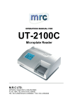
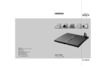
*LJDVHW
0 'DW D
The cordless USB interface
for connecting PCs to Gigaset 3070/75isdn
+RZWRXVHWKLVPDQXDO
Operating Instructions
Note
Please read the safety
precautions outlined in these
operating instructions before
putting the unit into service!
&RQWHQWV
,QGH[
+RZWRXVHWKLVPDQXDO
The following controls are available in Acrobat Reader or in the context menu (right mouse
button):
Click here when you see this hand.
Contents
Introduction . . . . . . . . . . . . . . . . . . . . . . . . . . . . . . . . . . . . . . . . . . . . . . . . . . . . . . . . . .9
What is a Gigaset M101 Data? . . . . . . . . . . . . . . . . . . . . . . . . . . . . . . . . . . . . . . . . . . . .9
Meaning of "local adapter" and "remote adapter" . . . . . . . . . . . . . . . . . . . . . . . . . . . . .10
Meaning of "base" and "portable part" . . . . . . . . . . . . . . . . . . . . . . . . . . . . . . . . . . . . . .10
Click here to jump to this section.
11. It may be useful to switch the operating mode from "AT commands
(PC)" to one of the two other operating modes. This setting concerns the protocol on the serial interface, especially the speed adjustment. "Setting the operating mode" on page 12.
12. Close the program with "OK".
In the event of errors or for further information, see "Configuration
program options" on page 10.
Click here to jump to this section.
A
Back
Click here to jump
to the table of
contents.
Click here to jump to
the index.
Jump back to the last
position shown.
2
Overview
Front
1.
Operating LED,
illuminated when power supply is
active,
see "LEDs" on page 20
2.
Data LED, illuminated during
data transfer operations
Side
Port for the USB cable
1
A
Back
Contents
Contents
How to use this manual . . . . . . . . . . . . . . . . . . . . . . . . . . . . . . . . . . . . . . . . . . . . . . . . . . . . . . . . 2
Overview . . . . . . . . . . . . . . . . . . . . . . . . . . . . . . . . . . . . . . . . . . . . . . . . . . . . . . . . . . . . . . . . . . . 1
Introduction . . . . . . . . . . . . . . . . . . . . . . . . . . . . . . . . . . . . . . . . . . . . . . . . . . . . . . . . . . . . . . . . 4
What is a Gigaset M105 Data? . . . . . . . . . . . . . . . . . . . . . . . . . . . . . . . . . . . . . . . . . . . . . . . . . . 4
Meaning of "local adapter" and "remote adapter" . . . . . . . . . . . . . . . . . . . . . . . . . . . . . . . . . . . . 4
Meaning of "base" and "portable part" . . . . . . . . . . . . . . . . . . . . . . . . . . . . . . . . . . . . . . . . . . . . . 5
Contents of the package . . . . . . . . . . . . . . . . . . . . . . . . . . . . . . . . . . . . . . . . . . . . . . . . . . . . . . . 5
Installation . . . . . . . . . . . . . . . . . . . . . . . . . . . . . . . . . . . . . . . . . . . . . . . . . . . . . . . . . . . . . . . . . . 6
Configuration . . . . . . . . . . . . . . . . . . . . . . . . . . . . . . . . . . . . . . . . . . . . . . . . . . . . . . . . . . . . . . . 7
Registering Gigaset M105 Data at Gigaset 3070isdn/3075isdn . . . . . . . . . . . . . . . . . . . . . . . . . 7
Registering Gigaset M105 Data at Gigaset M105 Data . . . . . . . . . . . . . . . . . . . . . . . . . . . . . . . 8
Registering Gigaset M105 Data at Gigaset M101 Data . . . . . . . . . . . . . . . . . . . . . . . . . . . . . . . 9
Configuration program options . . . . . . . . . . . . . . . . . . . . . . . . . . . . . . . . . . . . . . . . . . . . . . . 10
General . . . . . . . . . . . . . . . . . . . . . . . . . . . . . . . . . . . . . . . . . . . . . . . . . . . . . . . . . . . . . . . . . . . 10
Starting the configuration program . . . . . . . . . . . . . . . . . . . . . . . . . . . . . . . . . . . . . . . . . . . . . . 10
"Connection" tab . . . . . . . . . . . . . . . . . . . . . . . . . . . . . . . . . . . . . . . . . . . . . . . . . . . . . . . . . . . . 11
Upper section: connecting to the PC . . . . . . . . . . . . . . . . . . . . . . . . . . . . . . . . . . . . . . . . . . . . . 11
Lower section: DECT connection . . . . . . . . . . . . . . . . . . . . . . . . . . . . . . . . . . . . . . . . . . . . . . . 11
"Operating mode" tab . . . . . . . . . . . . . . . . . . . . . . . . . . . . . . . . . . . . . . . . . . . . . . . . . . . . . . . . 12
Setting the operating mode . . . . . . . . . . . . . . . . . . . . . . . . . . . . . . . . . . . . . . . . . . . . . . . . . . . . 12
Special settings for "Direct connection" mode . . . . . . . . . . . . . . . . . . . . . . . . . . . . . . . . . . . . 13
"Local adapter" tab . . . . . . . . . . . . . . . . . . . . . . . . . . . . . . . . . . . . . . . . . . . . . . . . . . . . . . . . . . 15
Changing the name . . . . . . . . . . . . . . . . . . . . . . . . . . . . . . . . . . . . . . . . . . . . . . . . . . . . . . . . . . 15
Change adapter type . . . . . . . . . . . . . . . . . . . . . . . . . . . . . . . . . . . . . . . . . . . . . . . . . . . . . . . . . 15
Registering a portable part . . . . . . . . . . . . . . . . . . . . . . . . . . . . . . . . . . . . . . . . . . . . . . . . . . . . 16
De-registering a portable part . . . . . . . . . . . . . . . . . . . . . . . . . . . . . . . . . . . . . . . . . . . . . . . . . . 17
Automatic enabling . . . . . . . . . . . . . . . . . . . . . . . . . . . . . . . . . . . . . . . . . . . . . . . . . . . . . . . . . . 17
"Remote adapter" tab . . . . . . . . . . . . . . . . . . . . . . . . . . . . . . . . . . . . . . . . . . . . . . . . . . . . . . . . 18
Changing the name . . . . . . . . . . . . . . . . . . . . . . . . . . . . . . . . . . . . . . . . . . . . . . . . . . . . . . . . . . 19
Change PIN ... . . . . . . . . . . . . . . . . . . . . . . . . . . . . . . . . . . . . . . . . . . . . . . . . . . . . . . . . . . . . . 19
LEDs . . . . . . . . . . . . . . . . . . . . . . . . . . . . . . . . . . . . . . . . . . . . . . . . . . . . . . . . . . . . . . . . . . . . . 20
LED 1: Gigaset M105 Data status . . . . . . . . . . . . . . . . . . . . . . . . . . . . . . . . . . . . . . . . . . . . . . . 20
LED 2: data transfer . . . . . . . . . . . . . . . . . . . . . . . . . . . . . . . . . . . . . . . . . . . . . . . . . . . . . . . . . 20
Notes on installation and operation . . . . . . . . . . . . . . . . . . . . . . . . . . . . . . . . . . . . . . . . . . . . . . 21
Place of installation . . . . . . . . . . . . . . . . . . . . . . . . . . . . . . . . . . . . . . . . . . . . . . . . . . . . . . . . . . 21
Temperature and ambient conditions . . . . . . . . . . . . . . . . . . . . . . . . . . . . . . . . . . . . . . . . . . . . 21
Why set an operating mode? Technical background . . . . . . . . . . . . . . . . . . . . . . . . . . . . . . . . 22
Special features when connecting two Gigaset M105 or M101 Data units . . . . . . . . . . . . . . . . 22
Notes on the COM interface . . . . . . . . . . . . . . . . . . . . . . . . . . . . . . . . . . . . . . . . . . . . . . . . . . . 22
2
A
Back
Contents
Tips&tricks, settings . . . . . . . . . . . . . . . . . . . . . . . . . . . . . . . . . . . . . . . . . . . . . . . . . . . . . . . . 24
Access to different V.24 terminals from a laptop: . . . . . . . . . . . . . . . . . . . . . . . . . . . . . . . . . . . 24
Sequential access from multiple computers to a terminal: . . . . . . . . . . . . . . . . . . . . . . . . . . . . 25
PC-PC direct cable connection: via RS232/V.24 interface . . . . . . . . . . . . . . . . . . . . . . . . . . . . 26
Setting the direct connection to the correct baud rate . . . . . . . . . . . . . . . . . . . . . . . . . . . . . . . . 26
Sharing files . . . . . . . . . . . . . . . . . . . . . . . . . . . . . . . . . . . . . . . . . . . . . . . . . . . . . . . . . . . . . . . . 33
Examples of PC-PC direct cable connection problems . . . . . . . . . . . . . . . . . . . . . . . . . . . . . . . 34
What happens if... . . . . . . . . . . . . . . . . . . . . . . . . . . . . . . . . . . . . . . . . . . . . . . . . . . . . . . . . . . 35
Support . . . . . . . . . . . . . . . . . . . . . . . . . . . . . . . . . . . . . . . . . . . . . . . . . . . . . . . . . . . . . . . . . . . 36
Updates and news on the Internet . . . . . . . . . . . . . . . . . . . . . . . . . . . . . . . . . . . . . . . . . . . . . . . 36
Notes on sending faxes directly from the PC . . . . . . . . . . . . . . . . . . . . . . . . . . . . . . . . . . . . . . 36
Problems with application programs . . . . . . . . . . . . . . . . . . . . . . . . . . . . . . . . . . . . . . . . . . . . . 37
Technical data . . . . . . . . . . . . . . . . . . . . . . . . . . . . . . . . . . . . . . . . . . . . . . . . . . . . . . . . . . . . . . 39
Safety precautions . . . . . . . . . . . . . . . . . . . . . . . . . . . . . . . . . . . . . . . . . . . . . . . . . . . . . . . . . . . 40
Index . . . . . . . . . . . . . . . . . . . . . . . . . . . . . . . . . . . . . . . . . . . . . . . . . . . . . . . . . . . . . . . . . . . . . 41
3
A
Back
Introduction
Introduction
What is a Gigaset M105 Data?
Your Gigaset M105 Data is a cordless USB interface for operation at the
Gigaset 3070/75isdn base station, at a second Gigaset M105 Data or at
a Gigaset M101 Data (V.24 interface).
A Gigaset M105 Data unit is powered via the USB port but operates like a COM interface with regard to data.
The USB cable cannot be extended!
You can thus use this cordless USB port for your PC as an alternative to
the integrated USB port at the Gigaset 3070/3075isdn base station.
Radio link
Remote adapter
Local adapter
Gigaset M105 Data features of a configuration program.
Meaning of "local adapter" and "remote adapter"
These names are used for identifying the adapters and their role in data
communication. The "Local adapter" is the adapter that performs all configurations (also for the "remote adapter"). This means that the Gigaset
M105 Data setup routine does not have to be installed on the second PC
in the case of a direct cable connection.
4
A
Back
Introduction
Meaning of "base" and "portable part"
This is an assignment in the DECT connection (Base FP = Fixed Part,
PP=Portable Part) and refers exclusively to the air interface. A base is the
same as a base station in Gigaset telephony. Here, portable part is the
same as handset. This is defined, for example, through the registration
option. Only one Gigaset M105 Data "Portable part" can have an active
connection to a Gigaset 3070/75isdn or a Gigaset M101/M105 Data
"Base". Up to 6 portable parts or up to 6 bases can be registered (multilink operation).
The Gigaset Repeater cannot be used to extend the radio
range for Gigaset M105 Data, although it can for Gigaset handsets.
Contents of the package
1. Gigaset M105 Data
2. CD-ROM with the installation program and operating instructions
3. Installation brochure
4. USB cable
5
A
Back
Introduction
Installation
Prerequisites for installation
For installation, you need:
z an IBM-compatible PC with the following configuration:
– Windows 98 operating system
– approx. 5 MB free hard disk memory
– 1 free USB slot activated in the PC’s BIOS
– CD-ROM drive,
z the CD-ROM containing the installation program
Installing
1. Switch on the PC.
2. Insert the CD in the CD-ROM drive.
3. Connect the USB port on the Gigaset M105 Data to the USB interface on
your PCs by means of the USB cable provided.
The hardware assistant appears on the screen.
4. If prompted to enter the source for the driver, enter the CD directory, for
Windows 98 = win98.
Confirm all displays with OK or Next. A new virtual COM port is now configured.
5. Click Install in the open Gigaset M 100 Data Setup.
The installation program starts up.
6
A
Back
Configuration
Configuration
The purpose of configuration is to register the Gigaset M105 Data unit at
a Gigaset 3070/3075isdn base station, at a second Gigaset M105 Data
or at a Gigaset M101 Data. You can only perform configuration with the
configuration program.
Registering Gigaset M105 Data at Gigaset 3070isdn/
3075isdn
Proceed as follows:
1. Install Gigaset M105 Data.
2. Switch Gigaset 3070/3075isdn to registration mode (press LED).
3. Start the Gigaset M105 Data configuration program.
4. Select the Local adapter tab.
5. Click the Register button and enter the base station PIN.
6. Find a registration location and click OK. The registration procedure
starts and the message "If the required base is ready for registration,
the local adapter logs on. Check that the base is ready for registration." appears on the screen.
The two devices are automatically synchronised. There is now one entry
in the Registered bases list.
7. Close the program with OK.
In the event of errors or for more information, see "Configuration program options" on page 10.
7
A
Back
Configuration
Registering Gigaset M105 Data at Gigaset M105 Data
Proceed as follows:
1. Connect both Gigaset M105 Data units to a PC.
2. Start the Set Gigaset program at both PCs.
3. Select the Local adapter tab at both PCs.
4. Change the type of Gigaset M105 Data at one of the PCs from "Portable
part" to "Base".
5. Click the Register button at both PCs.
At the PC connected to the "Base" type Gigaset M105 Data, a LED flashes in sequence to signal that the unit is ready for registration. The configuration program is now complete.
Further configuration is now performed exclusively at the PC connected
to the "Portable part" type Gigaset M105 Data. Enter the PIN at this PC.
This is "0000" by default.
6. Click OK. The registration operation starts and the message "If the required base is ready for registration, the local adapter logs on.
Check that the base is ready for registration." appears on the screen.
The two devices are automatically synchronised. There is now an entry
in the Registered bases list.
7. Give the local station a suitable name, e.g. "PC".
8. Select the Remote adapter tab and give this also a name, e.g. "Gigaset
3075isdn". The registered portable part also appears in the window here.
9. It may be useful to switch the operating mode from "AT commands (PC)"
to one of the other operating modes. This setting concerns the protocol
on the serial interface, in particular the speed adjustment. For more information, seer "Setting the operating mode" on page 12.
10. Close the program with OK.
In the event of errors or for further information, see "Configuration program options" on page 10.
8
A
Back
Configuration
Registering Gigaset M105 Data at Gigaset M101 Data
Proceed as follows:
1. If the M101 is not already in the default status, please ensure that the
M101 is operating as a "Base". Please refer to the configuration program
for the type display and the switch options.
2. Press and hold down the black button on the Gigaset M101 Data (Base).
After approx. 10 seconds, the LEDs indicate that the system is ready for
registration by flashing in sequence.
3. Start the Set Gigaset program at the PC connected to the Gigaset M105
Data unit.
4. Select the Local adapter tab. The type is "Portable part".
5. Click the Register button and enter the PIN.
6. Click OK. The registration procedure starts and the message "If the required base is ready for registration, the local adapter logs on.
Check that the base is ready for registration." appears on the screen.
The two devices are automatically synchronised. An entry now appears
in the Registered bases list.
7. Assign a suitable name to the local adapter, e.g. "PC".
8. Open the Remote adapter tab and assign a name to it, e.g. "Gigaset
3075isdn". The registered portable part now also appears in this window.
9. It may be useful to switch the operating mode from "AT commands (PC)"
to one of the other operating modes. This setting concerns the protocol
on the serial interface, especially the speed adjustment. For more information, see "Setting the operating mode" on page 12.
10. Close the program with OK.
In the event of errors or for further information, see "Configuration program options" on page 10.
9
A
Back
Configuration program options
Configuration program options
General
You will not need the majority of configuration options for the simple implementation of a Gigaset M105 Data unit downstream of a Gigaset 3070/
3075.
Starting the configuration program
Under Start, select Programs followed by Gigaset M100 Data and finally Set Gigaset.
The configuration program offers a dialog box entitled Properties of Gigaset M101 Data which contains the four tabs Connect, Operating
mode, Local adapter und Remote adapter.
A number of special fields are also provided for special inputs.
10
A
Back
Configuration program options
"Connection" tab
Upper section: connecting to the PC
You can set the virtual COM port at which the local adapter is connected
in the upper section of the tab.
We recommend leaving the option No automatic detection at program
start-up deactivated (as shown). The program then checks the existing
COM ports and determines where the adapter is connected. Manual interface selection is only recommended if there is more than one Gigaset
M105 Data unit connected to the PC.
As soon as the program finds an adapter or identifies the manually selected interface, it sends it the configuration command via the control
lines. This action switches the adapter to configuration status. This is indicated by the Status: display in the dialog box. Gigaset M105 Data can
only be configured under these conditions. Your Gigaset M105 Data will
automatically switch the adapter back to operating status at the end of the
program.
Lower section: DECT connection
This section indicates whether a radio connection exists and if so, to
which Remote adapter. It also indicates the quality of the connection.
A Remote adapter must be registered before it can be selected here.
11
A
Back
Configuration program options
"Operating mode" tab
Important:
The "Operating mode" tab is not active if the registered Remote adapter
is a Gigaset 3070/75isdn. In this case, no settings can be made in this
tab.
If one of the adapters is set to "AT commands (PC)" or "AVM compatible
(PC)", the other adapter must switch to the corresponding operating
mode "AT commands (device)" or "AVM compatible (device)". If one
adapter is switched to "Direct connection", the other adapter must also
be switched to this mode. The appropriate switches are performed automatically if you select an operating mode for a Gigaset M105 Data unit.
Setting the operating mode
Open the Operating mode tab and select one of the five modes:
The three connection types are used for different purposes:
Direct connection The permanent transmission parameters for the virtual COM port are manually set at the computer
without automatic baud rate or data format recognition. This is always useful if the device at the Remote adapter does not support baud rate or data
format recognition as performed by conventional
modems, e.g. in the case of a second PC.
AT commands
(PC)
Automatic recognition of the transmission parameters based on the data from the PC at the local
adapter.
12
A
Back
Configuration program options
Special settings for "Direct connection" mode
In Direct connection mode, the fields in the lower section of the dialog box
are activated: you can set the transmission parameters for the virtual
COM port at the PC.
Use the default settings if you do not want to change any other parameters. In the event of malfunctions, reduce the speed in the Bits per second
field. Set your communication software likewise to this value.
In the case of changes, only permitted values are accepted in the individual fields, even for manual inputs.
Dataflow control list
You can set whether the data transmission is controlled by the hardware
or software. The usual setting is Hardware (RTS/CTS). RTS means "Request To Send" and CTS means "Clear To Send".
13
A
Back
Configuration program options
fLocal flow control check box
Local flow control normally does not have to be activated except when operating low-memory V.24 terminals (in connection with Gigaset M101
Data). Activating local flow control can help in the event of data transmission problems (e.g. sending faxes, operating a serial printer).
When local flow control is active, the Gigaset M105 Data unit connected
to the V.24 terminal immediately stops outputting data in the direction of
the terminal when a STOP signal is received and saves this data in its
own memory. This ensures that the PC only sends data that can be processed by the transmission route (saved). If local flow control is not activated, the V.24 terminal’s STOP signal is transferred to the PC. During
this time (less than 10 ms), the PC continues to send data. All of this data
is output by the Gigaset M101 Data unit in the direction of the V.24 terminal. If the terminal does not have sufficient memory to receive this data,
the data is lost.
14
A
Back
Configuration program options
"Local adapter" tab
Changing the name
The purpose of adapter names is to provide a rapid overview. The local
adapter must be called "PC". The remote adapters should, if possible, be
named after the peripheral device connected, e.g. "3070/3075isdn" or
"Modem".
Adapter names can be changed by entering or changing a name in the
Name field. Names can contain letters and digits as well as blanks. The
name must not contain more than 20 characters.
Change adapter type
Normally, a portable part is operated at the PC and the base station is operated at the peripheral device. Other constellations, however, are possible in which both adapters are connected to a PC in order, for example,
to create a cordless data connection between two PCs. In this case, the
adapter type of one of Gigaset M105 Data units must be Base while the
adapter type of the other must be a Base. Or you can implement more
than one remote adapter in order to control a second PC or the modem
alternately. It may also be necessary here to change the adapter type at
one of the Gigaset M105 Data units.
z Ensure that the correct Gigaset M105 Data is connected at the PC.
z Select Change adapter type. The change is performed in the background. You can see that it has been performed when the information
in the Adapter type: line changes.
15
A
Back
Configuration program options
Registering a portable part
Both adapters are powered. The Gigaset M105 Data unit is connected to
the PC; start the "Set Gigaset" program.
Select the Local adapter tab.
The following dialog box appears:
Up to six registered devices can be entered in the Registered adapter
window. Depending on the adapter type of the local adapter, Registered
adapter or Registered bases is displayed.
Select a registration location and click Register.
The following window appears when the local adapter is a Base (factory
setting is "Portable part"):
16
A
Back
Configuration program options
Enter the PIN and click OK.
The portable part now searches for the base station and automatically
registers at it.
If registration is not possible (base station not in registration mode or not
powered, incorrect PIN), the system will indicate the necessary steps for
resolving this problem.
De-registering a portable part
Select the adapter in the window and click Unregister.
Automatic enabling
The automatic enabling feature is not available with Gigaset3070/75isdn.
The data connection is automatically enabled as soon as usage stops.
The "Permit automatic enabling:" feature eliminates the need to enable
the data connection manually. If the V.24 interface is not used for a set
length of time (no activity on the V.24 interface and control line DTR = 0),
then this is automatically enabled and can be automatically seized by another portable part. See "Remote adapter" tab on page 18.
If you permit automatic enabling, you must also define an enabling time.
17
A
Back
Configuration program options
"Remote adapter" tab
This tab is used for configuring the Remote adapter that is not connected
to the PC. Registration must be performed first so that the two Gigaset
M105 Data units can communicate.
The Remote adapter tab is only available after registration on
the Local adapter tab.
18
A
Back
Configuration program options
Changing the name
As for local adapter, see "Changing the name" on page 15.
Change PIN ...
Click Change PIN ....
Enter the old PIN (PIN: 1–8 digits, default: 0000) to obtain authorisation
to change the PIN and press the tab key.
Enter the new PIN and press the tab key.
Enter the new PIN in the Repeat new PIN field and click OK.
The PIN is changed if the new PINs entered are identical and if the correct
old PIN is entered. Otherwise, a warning appears.
The PIN of the Gigaset3070/75isdn unit cannot be changed as described.
19
A
Back
Configuration program options
LEDs
There are two LEDs on the front of the Gigaset M105 Data unit.
LED 1: Gigaset M105 Data status
LED 1 indicates stand-by mode:
LED 1 flashes slowly
The adapter is searching for the partner or
has not been registered.
LED 1 flashes quickly
The partner was found, the data connection
is not assigned to the transmission route.
LED 1 is constantly lit
The partner was found, the transmission
route is on stand-by.
LED 2: data transfer
LED 2 indicates the status of the transmission route of the interface:
LED 2 off
No data transfer
LED 2 flickers/is lit
Data transfer active
20
A
Back
Configuration program options
Notes on installation and operation
Place of installation
There must be a 220/230 V AC and 50 Hz power socket nearby.
The Gigaset M105 Data should not be installed in the immediate vicinity
of other electronic devices, such as hi-fi systems, office equipment or microwave ovens, otherwise there is a risk of mutual interference.
Place the Gigaset M105 Data unit on a level, non-slip surface. The device
feet do not leave any unsightly marks. However, in view of the many different varnishes and polishes currently used for furniture, the possibility
of marks being left cannot be ruled out.
Radio communication between Base and Portable part is based on the
DECT standard. The Gigaset M105 Data complies fully with the relevant
European directives. Should you nevertheless experience sound or picture distortion with your satellite signal receiving equipment, please get in
touch with your dealer to have it tested for shielding faults.
Depending on the ambient conditions, the maximum range for a radio
connection between the local adapter and the Remote adapter is approx.
300 m outdoors and approx. 50 m indoors.
Temperature and ambient conditions
Gigaset M105 Data is designed for operation in protected rooms with a
temperature range from +5 °C to +45 °C and 20 % to 75 % relative humidity.
Do not install the Gigaset M105 Data unit in damp environments, such as
a bathroom or laundry room. Do not expose it to direct sunlight or other
heat sources, such as radiators.
21
A
Back
Configuration program options
Why set an operating mode? Technical background
Configuration is always performed for both data modules on connection
link. In the case of registration at a Gigaset 3070/3075isdn, the transmission parameters are set automatically; apart from the assignment of a
name, no other settings are necessary.
Special features when connecting two Gigaset M105 or M101 Data units
A Gigaset M105 Data unit is powered via the USB port but operates like
a COM interface with regard to data. For this reason, the transmission
rate is also provided. The USB bus cable cannot be extended! When a
Gigaset M105 Data is connected to a Gigaset M101 Data, the firmware
version of the Gigaset M101 Data must be V2.0. This firmware can be
downloaded free of charge from the Internet site http://www.siemens.com/ic/products/cd/deutsch/index/support/pcsupport/Default.htm.
Î see "Access to different V.24 terminals from a laptop:" on page 24.
Î see "Sequential access from multiple computers to a terminal:" on
page 25.
Notes on the COM interface
Serial interfaces are more than connectors. They have an integrated dataflow control, control lines, data lines and an adjustable speed function.
Serial interface are used to transport data in various formats.
Modems are usually controlled with AT commands or proprietary protocols that they receive via their serial interface. On the basis of these commands, modems can recognise the data format and speed at which the
data is transferred. The automatic recognition of transmission parameters
is important and must be emulated by the radio link if a device that understands the AT or AVM-compatible commands and that is used for parameter synchronisation is connected to the remote adapter.
A cordless extension cable between a PC and, for example, a modem
must detect the transmission parameters to be used at the PC interface
for communication between this interface and the modem. On the modem
side, the functions generated by the PC must also be created for the serial interface.
On the radio link, data is transmitted according to a radio protocol that has
nothing to do with the serial interface.
If a device which cannot detect transmission parameters in the same way
as a modem is connected to the remote adapter, "Direct connection" is
selected as the operating mode.
22
A
Back
Configuration program options
There are five possible operating modes for every Gigaset M101/M105
Data:
1. Direct connection: this operating mode is implemented for all devices
that are not controlled with AT or AVM-compatible commands
2. AT commands (PC) or AVM compatible (PC): this is the operating
mode for the local adapter. The Gigaset M105 Data unit determines the
conditions on the serial interface in the same way as a modem. In addition
to the data, the transmission parameters are also transmitted to the Remote adapter which then transfers the data to the connected device.
3. AT commands (device) or AVM compatible (device): in this operating
mode, the remote adapter controls a terminal that understands AT commands.
23
A
Back
Tips&tricks, settings
Tips&tricks, settings
This section describes settings, implementation options and programming methods.
Access to different V.24 terminals from a laptop:
z All terminals (PC, modem, Gigaset 3070/3075isdn) can be accessed
from a laptop.
z Only one data connection at a time can ever be set up to a terminal.
z You must select the relevant connection partner in the configuration
mask in order to switch between the various terminals. This can be
done in the Connection partner: list in the Connection tab (Î page
11) and via the Connect button in the Local adapter tab (Î page 15).
z If Gigaset 3070/3075isdn, for example, is selected as the connection
partner, then an incoming call at the modem, for example, cannot be
signalled at the laptop. This is not resolved by "Permit automatic enabling:" feature (Î page 17).
24
A
Back
Tips&tricks, settings
Sequential access from multiple computers to a terminal:
z Multiple portable parts (PC, laptop) share a Gigaset 3070/3075isdn base (modem).
z Only one data connection at a time can ever be set up from a "portable
part to the terminal".
z Simultaneous access from both portable parts to the Gigaset 3070/
3075isdn modem is not possible.
z The data connection is automatically enabled if the data line is not accessed.
25
A
Back
Tips&tricks, settings
PC-PC direct cable connection: via RS232/V.24 interface
The problem that often occurs with PC-PC direct cable connection is incorrect baud rate setting. The following section describes the configuration of a PC-PC direct cable connection at a Win95 system (similar for
WIN98).
Before using the actual Gigaset M105 Data unit, application functionality
should be checked using a direct connection (with a null-modem cable).
After the test, remove the null-modem cable and install the cable supplied. This accelerates fault detection and clearance. If this is not possible, the precise configuration is to be examined.
z The Gigaset M105 Data unit can be set to a fixed baud rate (direct connection 115200 bps with HW handshake).
Setting the direct connection to the correct baud rate
1. Open the terminal program
First of all, open a terminal program (e.g. Win95 HyperTerminal via
Hypertrm.exe) at both PCs and ensure that the correct COM port is being
accessed.
Set up a direct connection via COMx (COM 1 was selected in the example). The virtual COM port must be selected when using the Gigaset
M105 Data.
26
A
Back
Tips&tricks, settings
Then set the port speed:
The baud rate (max. 115200) and HW handshake (default setting) are set
in this mask. If you can now transfer data from one PC to another, proceed with the second step.
2. Set the direct cable connection parameters
Exit the terminal program at one of the PCs. Under the Win95 Start menu,
select Settings > Control Panel and open the window Control Panel
window. Double-click the System icon (you should now see the System
Properties window). Select the Device Manager tab. Find the Modem
icon in the folder.
27
A
Back
Tips&tricks, settings
Double-click the icon to expand the branch. The setting Null-Modem Cable at COMx should be available. Select the appropriate COM port for
your configuration and double-click it to open another subfolder.
28
A
Back
Tips&tricks, settings
This Modem tab contains the setting for the maximum speed. This should
be set to 115200 bps.
Activate Hardware under Use flow control in Connection > Advanced.
Click OK to exit each window.
3. Test the baud rate setting
Open the direct cable connection program under
Start > Programs > Accessories.
If this icon is missing, you may have to reinstall the appropriate software
from the Win 95 system CD.
To do this, select Control Panel, Add/Remove Programs, Windows
Setup, Communications, Details, Direct Cable Connection.
29
A
Back
Tips&tricks, settings
Select Change and activate Guest. Then enter the interface, e.g. NullModem Cable at COM 1.
To enable access by the other PC, the host (controlling party) and guest
(accessing party) as well as the file and print sharing option must be activated.
30
A
Back
Tips&tricks, settings
Click File and Print Sharing in the sub-window.
Set the parameters here. If a change was made, new drivers are loaded
and Windows must be restarted.
If file and print sharing was already activate, the computer does not need
to be restarted. Otherwise, restart your computer.
31
A
Back
Tips&tricks, settings
If the system was not restarted, the following window appears:
If file/printer sharing has not yet been activated, start to activate it, see
"Sharing files" on page 33.
In the final window, select Finish and click OK to answer the questions.
A window entitled Direct Cable Connection with the status Accessing
%1!s should now appear.
The message CLIENT should appear a number of times in the terminal
program of the connected computer.
If this is the case, repeat the steps already described at the other computer.
If the Client message does not appear, please try the following:
z Close the Direct Cable Connection window.
z Open the Task Manager by pressing <CTRL> <ALT> <DEL>. If you
see a task called Rnaapp, select it and end it by clicking End Task.
z Repeat step 2 and step 3.
If this is unsuccessful, the problem may have a different source.
32
A
Back
Tips&tricks, settings
Sharing files
Since the Windows information in the previous mask is somewhat confusing, and since no references are made to the File Manager/Explorer, here
is the correct procedure. Once file sharing has been activated and the PC
restarted, you can release files for processing by the other PC via the File
Manager/Explorer.
Start the Explorer:
Select the relevant folder and the click File1 > Properties. The following
window containing the tabs General and Release appears:
33
A
Back
Tips&tricks, settings
Assign the other PC user access rights to the files on your hard disk, or
where applicable, activate password protection.
Files that support sharing are identified as follows:
shared
not shared
Examples of PC-PC direct cable connection problems
Other modem drivers installed continue to operate at the same COM port
(special ISDN TA drivers, CAPI modem drivers or similar software are often the cause of the problem).
Once successfully put into service, you can start up the direct cable connection at both computers. Do not forget that one PC must be set as the
host and the other as the guest. Access to files should also be enabled
via the settings Network/File and Print Sharing.
Finally, the subfolders to be accessed by the guest must be released via
the Explorer.
1.
Error in the Windows help, the Properties submenu is not described.
34
A
Back
What happens if...
What happens if...
If a malfunction occurs, check the following points:
z The USB cable connections to the connected devices are fully inserted.
z The adapters are not too far apart and there are no large parts of buildings in between (see "Place of installation" on page 21).
z Registration was successful.
When operating Gigaset 105 Data with Gigaset 101 Data:
z The local adapter operating mode is set to AT commands (PC) or
AVM compatible (PC).
Or:
z The local adapter operating mode is set to Direct connection and you
have set the direct connection transmission parameters in your communication software.
If the malfunction persists after checking all the above points, call the hotline at 0180 5 333 220.
If you are in Austria and your unit
z is connected to a single connection, contact the Siemens hotline at 01/
1707-5004
z is connected to a telephone system, contact the relevant installation
company, e.g. Siemens Nebenstellenanlagen in Vienna, NÖ, Bgld. Telephone: 01/1705
Siemens Service should only be contacted if problems develop with the
device. Your specialist dealer will be happy to answer any questions concerning unit operation. Contact your network operator/provider for questions concerning telephone connection.
Internet: www.siemens.com/ic/products/cd/deutsch/index/support/
pcsupport/download.htm#M105
35
A
Back
What happens if...
Support
Updates and news on the Internet
www.siemens.com/pc-communication-support
Notes on sending faxes directly from the PC
You may encounter problems if your PC program uses Class 1 fax mode.
Class 1 does not support signal runtime delays which are required for
switching to radio mode.
Class 2 mode, on the other hand is less sensitive. Nevertheless, interference can still occur here due to a bad radio link. If you have problems with
this setting, start the configuration program and check the transmission
quality under Connection and improve the quality of the connection by
moving the Gigaset M105 Data unit slightly.
36
A
Back
What happens if...
Configuration management
Fault
Cause
Solution
Message from configura- The COM port used is being
tion program: "Data adapt- used by another program.
er not found..."
Close the application that is using
the COM port.
Message from configura- The base station may not have
tion program: Registration been ready for registration or
not possible.
the radio connection was temporarily affected by "external
influences".
Repeat registration with a base that
is ready. The PIN must be entered
for this (factory setting: "0000").
See "Registering a portable part"
on page 16.
PIN entered is rejected
If you forgot the current PIN, reset
the Gigaset M105 Data unit to the
factory defaults. The preset PIN is
"0000".
The PIN entered does not
match the valid PIN.
Problems with application programs
Fault
Cause
Solution
Baud rate not correctly set.
See "PC-PC direct cable connection: via RS232/V.24 interface"
on page 26.
Fax function is not working. SW and modem simulate a
Class1 fax.
Class 1 fax mode is not supported
by Gigaset M105 Data for technical
reasons. Gigaset M105 Data supports Class 2 fax mode.
PC-PC direct cable connection under WIN98 cannot be configured or is not
working.
Find out about additional settings in the modem manual or description of your fax software. (The AT command AT+FCLASS=? is useful, provided this is supported by the modem. If the modem’s answer
string contains a 2, then your modem supports Class 2 fax mode).
Programs that use DCD
The DCD output at the local
Use a null-modem cable at the re(Data Carrierer Detect) are adapter is controlled by the
mote adapter.
not working properly.
DCD input at the remote adapter.
37
A
Back
What happens if...
Fault
Cause
Solution
The modem parameter request function is not working or is not correct.
Windows does not follow the
AT Hayes conditions.
Data transmission with
Xmodem is very slow.
Xmodem operates in half-du- Use another transmission protocol,
plex mode. The transmitting
e.g. Zmodem.
unit waits for acknowledgement after each data package.
The signal delay (20–30 ms per
data block at the DECT interface) significantly reduces the
transmission speed.
Laplink 7.0 is not working.
Data transmission is switched None
during transmission, AT Hayes
commands are not used for
this.
Technically specified time deFor example, under Win 98 lay that are not supported by
with <Start><Setthe modem’s driver software.
tings><Control Panel><Modems><Diagnostics><More Info>
None
None
Miscellaneous
Fault
Cause
Solution
Monitor fault when Gigaset
DECT HF wanted signals is in- Move Gigaset M105 Data
M105 Data is active (e.g. slight fluencing the monitor.
along the longitudinal axis until
flickering or moiré effect).
the interference disappears.
Move Gigaset M105 Data further away from the monitor.
A slight humming can be heard
in the loudspeakers connected
to the sound card when Gigaset M105 Data is active.
DECT HF wanted signal is demodulated by the analog components of the sound card or
the amplifiers of the active
speakers and thus produces a
humming sound.
Move Gigaset M105 Data
along the longitudinal axis until
the interference disappears.
Move Gigaset M105 Data further away from the sound card/
loudspeakers.
38
A
Back
What happens if...
Technical data
DECT =Digital Enhanced Cordless Telecommunications
Number of channels: 120 duplex channels
Standard:
Radio frequency range: 1880 MHz to1900 MHz
Transmitted power:
10 mW, average rating per channel
Range: up to 300 m outdoors,
up to 50 m indoors
Power supply: USB powered
Power consumption:
Permissible ambient
conditions for operation:
Stand-by mode: approx. 4 W
Data transfer mode: approx. 5 W
+5 °C to +45 °C
20 % to 75 % relative humidity
USB port: Type B socket
Standards complied
with:
DECT in accordance with CTR 6
Electrical safety in accordance with EN 60950
39
A
Back
What happens if...
Safety precautions
Medical equipment can be affected by DECT devices.
Gigaset M105 Data can cause unpleasant humming in hearing
aids.
Do not install Gigaset M105 Data in bathrooms or showers.
Do not operate Gigaset M105 Data in environments where
there is risk of explosion.
Do not forget to include the operating instructions and CD when
passing on Gigaset M105 Data to a third party.
Gigaset M105 Data is designed for operation in your country as indicated
on the back of the unit. Special country-specific features have been implemented. Your specialist dealer or network provider will be happy to answer any questions with regard to differences in public telephone networks.
The compliance of the unit with the basic R&TTE requirements of the terminal directive is certified by the CE symbol.
We, Siemens AG, declare, that the above mentioned product is manufactured
according to our Full Quality Assurance System certified by CETECOM ICT
Services GmbH with the registration number "Q810820M" in compliance with
ANNEX V of the R&TTE-Directive 99/05/EC. The presumption of conformity
with the essential requirements regarding Council Directive 99/05/EC is
ensured.
Senior Approvals Manager
40
A
Back
Index
Index
Numerics
Flow control
3070isdn/3075isdn
7
14
H
A
Hardware (RTS/CTS) 13
Adapter type, changing 15
Ambient conditions 21
AT commands 12
AT commands or AVM compatible
Automatic enabling 17
I
23
Implementation options 24
Initial configuration 7
Installation 6
B
L
Base 5
Baud rate, setting
Laplink 7.0 38
Laptop 24
LEDs 20
Local adapter 4, 15
Local flow control 14
Loudspeaker hums slightly
26
C
Changing the name 15
Class 2 fax operation 37
Clear To Send 13
COM port, setting 11
Configuration program
starting 10
Connection 11
38
M
Memory 6
Modem 24
Monitor flickers slightly
Multilink operation 5
D
38
Data adapter not found 37
Data transfer LED 20
DCD programs do not operate properly 37
DECT 39
DECT connection 11
Direct cable connection parameters 27
Direct connection 12, 13, 23
Download 22
N
E
PC 24
PC-PC direct cable connection 26
PC-PC direct cable connection under
WIN98 37
PIN rejected 37
Enabling time
17
F
Fax function does not work
37
Notes on the COM interface 22
O
Operating mode 12, 22
Operating mode, setting 12
Operating systems 6
P
41
Back
Index
T
PIN, changing 19
Place of installation 21
Portable part 5
Program, installing 6
R
Registering at 3070isdn/3075isdn 7
Registering at Gigaset M101 Data 9
Registering at Gigaset M105 Data 8
Registration not possible 37
Remote adapter 4, 18
de-registering 17, 18
registering 16
Request To Send 13
S
Special features
Status LED 20
Tab
Connection 11
Local adapter 15
Operating mode 12
Remote adapter 18
Tips 24
U
USB bus cable and M105 4, 22
W
What happens if...
35
X
22
Xmodem
38
42
Back