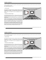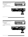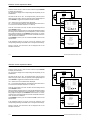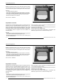
1
BARCO PROJECTION SYSTEMS
GRAPHICS
8200
R9001330
OWNER'S MANUAL
Art. No. :R5975288
Date: 110497
BARCO PROJECTION SYSTEMS
GRAPHICS
8200
R9001330
OWNER'S MANUAL
Date: 110497
Art. No. :R5975288
Due to constant research, the information in this manual is subject
to change without notice.
Produced by BARCO NV, April 1997.
All rights reserved.
Trademarks are the rights of their respective owners.
Printed in Belgium
Due to constant research, the information in this manual is subject
to change without notice.
Produced by BARCO NV, April 1997.
All rights reserved.
Trademarks are the rights of their respective owners.
Printed in Belgium
Table of Contents
WARNINGS & SAFETY INSTRUCTIONS ....................................................................................................................................... 1-1
AVERTISSEMENTS & PRESCRIPTIONS DE SECURITE .............................................................................................................. 1-1
UNPACKING & DIMENSIONS ........................................................................................................................................................
Unpacking ............................................................................................................................................................................
Projector dimensions ............................................................................................................................................................
Battery installation in the RCU. .............................................................................................................................................
2-1
2-2
2-3
2-4
INSTALLATION GUIDELINES ........................................................................................................................................................
Installation guidelines ..........................................................................................................................................................
* Environment ......................................................................................................................................................................
* What about ambient light ? ................................................................................................................................................
* Which screen type? ...........................................................................................................................................................
* What image size? How big should the image be? .............................................................................................................
* Where to install the projector? ...........................................................................................................................................
* How to install a projection lens? ........................................................................................................................................
3-1
3-2
3-2
3-2
3-3
3-3
3-4
3-6
INSTALLATION SET UP ................................................................................................................................................................. 4-1
LOCATION AND FUNCTION OF CONTROLS ................................................................................................................................ 5-1
Front panel terminology ....................................................................................................................................................... 5-2
Control Panel Terminology ................................................................................................................................................... 5-3
POWER CONNECTION ..................................................................................................................................................................
Power cord connection .........................................................................................................................................................
Fuses ...................................................................................................................................................................................
Switching on ........................................................................................................................................................................
Switching to stand-by ...........................................................................................................................................................
Switching off ........................................................................................................................................................................
6-1
6-2
6-2
6-3
6-4
6-4
INPUT MODULE CONNECTIONS ..................................................................................................................................................
Input connections. ................................................................................................................................................................
Input module insertion into the projector ...............................................................................................................................
Video/S-video input module .................................................................................................................................................
7-1
7-2
7-2
7-3
i-1
5975288 BARCOGRAPHICS 8200 110497
Table of Contents
WARNINGS & SAFETY INSTRUCTIONS ....................................................................................................................................... 1-1
AVERTISSEMENTS & PRESCRIPTIONS DE SECURITE .............................................................................................................. 1-1
UNPACKING & DIMENSIONS ........................................................................................................................................................
Unpacking ............................................................................................................................................................................
Projector dimensions ............................................................................................................................................................
Battery installation in the RCU. .............................................................................................................................................
2-1
2-2
2-3
2-4
INSTALLATION GUIDELINES ........................................................................................................................................................
Installation guidelines ..........................................................................................................................................................
* Environment ......................................................................................................................................................................
* What about ambient light ? ................................................................................................................................................
* Which screen type? ...........................................................................................................................................................
* What image size? How big should the image be? .............................................................................................................
* Where to install the projector? ...........................................................................................................................................
* How to install a projection lens? ........................................................................................................................................
3-1
3-2
3-2
3-2
3-3
3-3
3-4
3-6
INSTALLATION SET UP ................................................................................................................................................................. 4-1
LOCATION AND FUNCTION OF CONTROLS ................................................................................................................................ 5-1
Front panel terminology ....................................................................................................................................................... 5-2
Control Panel Terminology ................................................................................................................................................... 5-3
POWER CONNECTION ..................................................................................................................................................................
Power cord connection .........................................................................................................................................................
Fuses ...................................................................................................................................................................................
Switching on ........................................................................................................................................................................
Switching to stand-by ...........................................................................................................................................................
Switching off ........................................................................................................................................................................
6-1
6-2
6-2
6-3
6-4
6-4
INPUT MODULE CONNECTIONS ..................................................................................................................................................
Input connections. ................................................................................................................................................................
Input module insertion into the projector ...............................................................................................................................
Video/S-video input module .................................................................................................................................................
7-1
7-2
7-2
7-3
5975288 BARCOGRAPHICS 8200 110497
i-1
Table of Contents
RGB analog input module. ................................................................................................................................................... 7-6
Component input module. .................................................................................................................................................... 7-9
RGB3S/RG3sB input module. ............................................................................................................................................. 7-11
Connecting a computer, e.g. IBM PC (or compatible), Apple Macintosh to the RS 232 input of the projector. ...................... 7-13
Set up of the baud rate for communication with a computer. ............................................................................................... 7-13
Connecting a RCVDS 05 to the projector. ........................................................................................................................... 7-14
Connecting a VS05 to the projector. .................................................................................................................................... 7-14
Connecting an IR Remote Receiver 800 to the projector. .................................................................................................... 7-14
CONTROLLING ..............................................................................................................................................................................
How to use the RCU? ..........................................................................................................................................................
Projector address .................................................................................................................................................................
How to display a projector address? .....................................................................................................................................
How to program an address into the RCU? ..........................................................................................................................
Picture controls with direct access. ......................................................................................................................................
8-1
8-2
8-3
8-4
8-4
8-4
START UP OF THE ADJUSTMENT MODE ..................................................................................................................................... 9-1
Adjustment Mode ................................................................................................................................................................. 9-2
GUIDED ADJUSTMENT MODE .................................................................................................................................................... 10-1
RANDOM ACCESS ADJUSTMENT MODE .................................................................................................................................. 11-1
Starting up the Random Access Adjustment Mode ............................................................................................................ 11-2
File service ........................................................................................................................................................................ 11-3
Load file ............................................................................................................................................................................. 11-4
Edit file ............................................................................................................................................................................... 11-5
Rename ............................................................................................................................................................................. 11-9
Copy ................................................................................................................................................................................ 11-10
Delete .............................................................................................................................................................................. 11-11
File Options ..................................................................................................................................................................... 11-12
Picture Tuning ................................................................................................................................................................. 11-12
Sync slow/fast .................................................................................................................................................................. 11-13
Still Video ......................................................................................................................................................................... 11-13
Color Balance .................................................................................................................................................................. 11-14
i-2
5975288 BARCOGRAPHICS 8200 110497
Table of Contents
RGB analog input module. ................................................................................................................................................... 7-6
Component input module. .................................................................................................................................................... 7-9
RGB3S/RG3sB input module. ............................................................................................................................................. 7-11
Connecting a computer, e.g. IBM PC (or compatible), Apple Macintosh to the RS 232 input of the projector. ...................... 7-13
Set up of the baud rate for communication with a computer. ............................................................................................... 7-13
Connecting a RCVDS 800 or RCVDS 05 to the projector. ................................................................................................... 7-14
Connecting a VS05 to the projector. .................................................................................................................................... 7-14
Connecting an IR Remote Receiver 800 to the projector. .................................................................................................... 7-14
CONTROLLING ..............................................................................................................................................................................
How to use the RCU? ..........................................................................................................................................................
Projector address .................................................................................................................................................................
How to display a projector address? .....................................................................................................................................
How to program an address into the RCU? ..........................................................................................................................
Picture controls with direct access. ......................................................................................................................................
8-1
8-2
8-3
8-4
8-4
8-4
START UP OF THE ADJUSTMENT MODE ..................................................................................................................................... 9-1
Adjustment Mode ................................................................................................................................................................. 9-2
GUIDED ADJUSTMENT MODE .................................................................................................................................................... 10-1
RANDOM ACCESS ADJUSTMENT MODE .................................................................................................................................. 11-1
Starting up the Random Access Adjustment Mode ............................................................................................................ 11-2
File service ........................................................................................................................................................................ 11-3
Load file ............................................................................................................................................................................. 11-4
Edit file ............................................................................................................................................................................... 11-5
Rename ............................................................................................................................................................................. 11-9
Copy ................................................................................................................................................................................ 11-10
Delete .............................................................................................................................................................................. 11-11
File Options ..................................................................................................................................................................... 11-12
Picture Tuning ................................................................................................................................................................. 11-12
Sync slow/fast .................................................................................................................................................................. 11-13
Still Video ......................................................................................................................................................................... 11-13
Color Balance .................................................................................................................................................................. 11-14
i-2
5975288 BARCOGRAPHICS 8200 110497
Table of Contents
Gamma ............................................................................................................................................................................
Geometry .........................................................................................................................................................................
Shift .................................................................................................................................................................................
Size .................................................................................................................................................................................
Side keystone ..................................................................................................................................................................
Blanking ...........................................................................................................................................................................
Options ............................................................................................................................................................................
11-15
11-16
11-16
11-17
11-18
11-19
11-21
INSTALLATION .............................................................................................................................................................................
Starting up the Installation Mode ........................................................................................................................................
Input Slots ..........................................................................................................................................................................
Convergence .....................................................................................................................................................................
Configuration .....................................................................................................................................................................
Internal Patterns ................................................................................................................................................................
Configuration .....................................................................................................................................................................
12-1
12-2
12-3
12-4
12-9
12-9
12-9
SERVICE MODE ........................................................................................................................................................................... 13-1
Starting up the Service Mode ............................................................................................................................................. 13-2
Identification ...................................................................................................................................................................... 13-5
Change Password ............................................................................................................................................................. 13-7
How to enable or disable the password function ? ............................................................................................................. 13-7
How to change the password ? .......................................................................................................................................... 13-9
Change Language ............................................................................................................................................................. 13-9
Change Projector Address ............................................................................................................................................... 13-10
Change Baudrate PC ....................................................................................................................................................... 13-10
Reset Lamp Runtime ....................................................................................................................................................... 13-11
Lamp Run Time History ................................................................................................................................................... 13-12
Panel Adjustments ........................................................................................................................................................... 13-13
Preset Input Balance ....................................................................................................................................................... 13-14
60 Hz Tracking ................................................................................................................................................................ 13-15
I2C diagnosis. .................................................................................................................................................................. 13-16
OPTIONAL EQUIPMENT .............................................................................................................................................................. 14-1
IR Receiver 800 ................................................................................................................................................................. 14-2
i-3
5975288 BARCOGRAPHICS 8200 110497
Table of Contents
Gamma ............................................................................................................................................................................
Geometry .........................................................................................................................................................................
Shift .................................................................................................................................................................................
Size .................................................................................................................................................................................
Side keystone ..................................................................................................................................................................
Blanking ...........................................................................................................................................................................
Options ............................................................................................................................................................................
11-15
11-16
11-16
11-17
11-18
11-19
11-21
INSTALLATION .............................................................................................................................................................................
Starting up the Installation Mode ........................................................................................................................................
Input Slots ..........................................................................................................................................................................
Convergence .....................................................................................................................................................................
Configuration .....................................................................................................................................................................
Internal Patterns ................................................................................................................................................................
Configuration .....................................................................................................................................................................
12-1
12-2
12-3
12-4
12-9
12-9
12-9
SERVICE MODE ........................................................................................................................................................................... 13-1
Starting up the Service Mode ............................................................................................................................................. 13-2
Identification ...................................................................................................................................................................... 13-5
Change Password ............................................................................................................................................................. 13-7
How to enable or disable the password function ? ............................................................................................................. 13-7
How to change the password ? .......................................................................................................................................... 13-9
Change Language ............................................................................................................................................................. 13-9
Change Projector Address ............................................................................................................................................... 13-10
Change Baudrate PC ....................................................................................................................................................... 13-10
Reset Lamp Runtime ....................................................................................................................................................... 13-11
Lamp Run Time History ................................................................................................................................................... 13-12
Panel Adjustments ........................................................................................................................................................... 13-13
Preset Input Balance ....................................................................................................................................................... 13-14
60 Hz Tracking ................................................................................................................................................................ 13-15
I2C diagnosis. .................................................................................................................................................................. 13-16
OPTIONAL EQUIPMENT .............................................................................................................................................................. 14-1
IR Receiver 800 ................................................................................................................................................................. 14-2
5975288 BARCOGRAPHICS 8200 110497
i-3
Table of Contents
Hardwired RCU. .................................................................................................................................................................. 14-2
RCVDS 05 .......................................................................................................................................................................... 14-3
VS05 ................................................................................................................................................................................... 14-3
MAGIK Interface ................................................................................................................................................................. 14-4
Adapter and communication cables ..................................................................................................................................... 14-4
Ceiling Mount Kit CM100 ..................................................................................................................................................... 14-5
Projector Transport Handle ................................................................................................................................................. 14-6
Projector Frame for Dual or Triple Configurations ................................................................................................................ 14-6
Multifunctional flight case .................................................................................................................................................... 14-7
Mechanical Shutter ............................................................................................................................................................. 14-8
Adjustable lensholder .......................................................................................................................................................... 14-8
Appendix A : Standard source set up files. ...................................................................................................................................... A-1
Appendix B : Battery replacement in the RCU. ................................................................................................................................ B-1
Appendix C : Focusing the lens ....................................................................................................................................................... C-1
Appendix D : Lens Cleaning Procedure ........................................................................................................................................... D-1
Appendix E : Source numbers 90 - 99 ............................................................................................................................................. E-1
Appendix F : Lenses ........................................................................................................................................................................ F-1
i-4
5975288 BARCOGRAPHICS 8200 110497
Safety Instructions
WARNINGS
AVERTISSEMENTS
Safety instructions
Prescriptions de securite
On safety
Securite
On installation
Installation
On servicing
Entretien et reparation
On cleaning
Nettoyage
On repacking
Re-emballage
On illumination
Eclairage
1-1
5975288 BARCOGRAPHICS 8200 110497
Safety Instructions
WARNINGS
AVERTISSEMENTS
Safety instructions
Prescriptions de securite
On safety
Securite
On installation
Installation
On servicing
Entretien et reparation
On cleaning
Nettoyage
On repacking
Re-emballage
On illumination
Eclairage
5975288 BARCOGRAPHICS 8200 110497
1-1
Prescription de sécurtié
Remarque sur la Sécurité
DONNEES POUR LE PROPRIETAIRE
Les projecteurs sont fabriqués conformément aux exigences des
normes de sécurité internationales IEC950, UL 1950 et CSA C22.2
No. 950. Ces normes de sécurité sont imposées aux équipements de
la technologie informatique incluant les équipements électriques.
Le numéro de pièce et le numéro de série sont situés à l’arrière du
projecteur. Copier ces numéros dans les espaces prévus ci-dessous.
Se référer à ces numéros chaque fois que vous consultez votre agent
BARCO concernant cet appareil.
Ces normes de sécurité imposent des exigences importantes sur NUMERO DE PIECE :
l’emploi des composantes, des matériaux et de l’isolation dont la
sécurité est critique, afin de protéger l’utilisateur contre le risque d’une NUMERO DE SERIE :
décharge électrique et d’avoir accès aux parties sous tension.
Les normes de sécurité aussi imposent des limitations concernant la AGENT :
hausse de la température interne et externe, les niveaux de radiation,
la stabilité et la force mécanique, la construction du cadre métallique
à l’intérieure et la protection contre les risques d’incendie.
Les épreuves auxquelles l’équipement a été subi assurent la sécurité
totale de l’utilisateur, même lorsque l’équipement ne fonctionne pas
normalement.
Instructions pour l’installation
Lire ce manuel complètement avant de mettre l’appareil en fonctionnement et le conserver pour consultation ultérieure.
L’installation et les réglages préliminaires devraient être faits par du
personnel qualifié BARCO ou par des agents autorisés du service
BARCO.
1-2
5975288 BARCOGRAPHICS 8200 110497
Presciptions de sécurité
Remarque sur la Sécurité
DONNEES POUR LE PROPRIETAIRE
Les projecteurs sont fabriqués conformément aux exigences des
normes de sécurité internationales IEC950, UL 1950 et CSA C22.2
No. 950. Ces normes de sécurité sont imposées aux équipements de
la technologie informatique incluant les équipements électriques.
Le numéro de pièce et le numéro de série sont situés à l’arrière du
projecteur. Copier ces numéros dans les espaces prévus ci-dessous.
Se référer à ces numéros chaque fois que vous consultez votre agent
BARCO concernant cet appareil.
Ces normes de sécurité imposent des exigences importantes sur NUMERO DE PIECE :
l’emploi des composantes, des matériaux et de l’isolation dont la
sécurité est critique, afin de protéger l’utilisateur contre le risque d’une NUMERO DE SERIE :
décharge électrique et d’avoir accès aux parties sous tension.
Les normes de sécurité aussi imposent des limitations concernant la AGENT :
hausse de la température interne et externe, les niveaux de radiation,
la stabilité et la force mécanique, la construction du cadre métallique
à l’intérieure et la protection contre les risques d’incendie.
Les épreuves auxquelles l’équipement a été subi assurent la sécurité
totale de l’utilisateur, même lorsque l’équipement ne fonctionne pas
normalement.
Instructions pour l’installation
Lire ce manuel complètement avant de mettre l’appareil en fonctionnement et le conserver pour consultation ultérieure.
L’installation et les réglages préliminaires devraient être faits par du
personnel qualifié BARCO ou par des agents autorisés du service
BARCO.
1-2
5975288 BARCOGRAPHICS 8200 110497
Safety Instructions
Notice on safety
OWNER’S RECORD
Projectors are built in accordance with the requirements of the
international safety standards IEC950, UL 1950 and CSA C22.2 No.
950, which are the safety standards of information technology equipment including electrical business equipment.
The part number and serial number are located at the rear of the
projector. Record these numbers in the spaces provided below. Refer
to them whenever you call upon your BARCO dealer regarding this
product.
These safety standards impose important requirements on the use of PART NUMBER:
safety critical components, materials and isolation, in order to protect
the user or operator against the risk of electric shock and energy SER. NUMBER:
hazard, and having access to live parts.
Safety standards also impose to the internal and external temperature DEALER:
rises, radiation levels, mechanical stability and strength, enclosure
construction and protection against risk of fire.
Simulated single fault condition testing ensures the safety of the
equipment to the user even when the equipment's normal operation
fails.
Installation instructions
Before operating your projector please read this manual thoroughly,
and retain it for future reference.
Installation and preliminary adjustments should be performed by
qualified BARCO personnel or authorized BARCO service dealers.
1-3
5975288 BARCOGRAPHICS 8200 110497
Safety Instructions
Notice on safety
OWNER’S RECORD
Projectors are built in accordance with the requirements of the
international safety standards IEC950, UL 1950 and CSA C22.2 No.
950, which are the safety standards of information technology equipment including electrical business equipment.
The part number and serial number are located at the rear of the
projector. Record these numbers in the spaces provided below. Refer
to them whenever you call upon your BARCO dealer regarding this
product.
These safety standards impose important requirements on the use of PART NUMBER:
safety critical components, materials and isolation, in order to protect
the user or operator against the risk of electric shock and energy SER. NUMBER:
hazard, and having access to live parts.
Safety standards also impose to the internal and external temperature DEALER:
rises, radiation levels, mechanical stability and strength, enclosure
construction and protection against risk of fire.
Simulated single fault condition testing ensures the safety of the
equipment to the user even when the equipment's normal operation
fails.
Installation instructions
Before operating your projector please read this manual thoroughly,
and retain it for future reference.
Installation and preliminary adjustments should be performed by
qualified BARCO personnel or authorized BARCO service dealers.
5975288 BARCOGRAPHICS 8200 110497
1-3
Prescription de sécurtié
ATTENTION
RISQUE D'ELECTROCUTION NE PAS OUVRIR
ATTENTION : AFIN DE REDUIRE LE RISQUE DE CHOCS
ELECTRIQUES, NE PAS ENLEVER LE COUVERCLE (OU LE DOS)
IL N'Y A PAS DE PIECES REPARABLES PAR L'UTILISATEUR A
L'INTERIEUR
LE SERVICE NE PEUT ETRE EFFECTUE QUE PAR DU PERSONNEL
QUALIFIÉ
L’éclair avec une tête de flèche dans un
triangle indique à l’utilisateur que les pièces à
l’intérieur de l’appareil présentent un risque
de chocs électriques.
Le point d’exclamation dans un triangle indique
à l’utilisateur que des instructions de fonctionnement et/ou de service sont comprises dans la
documentation technique de cet équipement.
AVERTISSEMENT
POUR EVITER DES RISQUES D’INCENDIE OU DE CHOCS ELECTRIQUES, NE PAS
EXPOSER CE PROJECTEUR A LA PLUIE OU A L’HUMIDITE
Fédéral communication commission (FCC statement)
Cet équipement a été testé et trouvé conforme aux limites imposées
aux appareils digitaux de classe A, selon la section 15 des règles
FCC. Ces limites sont conçues pour fournir une protection raisonnable contre les interférences lorsque l’utilisation doit se faire dans un
environnement commercial. Cet équipement génère, utilise et peut
émettre de l’énergie aux fréquences radio, et s’il n’est pas installé et
utilisé conformément aux instructions du manuel, il peut créer des
interférences désavantageuses dans les communications radio.
L’utilisation de cet équipement dans des zones résidentielles peut
créer des interférences. Le cas échéant, l’utilisateur devra prendre
toutes les mesures requises pour les amoindrir, à ses propres frais.
1-4
5975288 BARCOGRAPHICS 8200 110497
Presciptions de sécurité
ATTENTION
RISQUE D'ELECTROCUTION NE PAS OUVRIR
ATTENTION : AFIN DE REDUIRE LE RISQUE DE CHOCS
ELECTRIQUES, NE PAS ENLEVER LE COUVERCLE (OU LE DOS)
IL N'Y A PAS DE PIECES REPARABLES PAR L'UTILISATEUR A
L'INTERIEUR
LE SERVICE NE PEUT ETRE EFFECTUE QUE PAR DU PERSONNEL
QUALIFIÉ
L’éclair avec une tête de flèche dans un
triangle indique à l’utilisateur que les pièces à
l’intérieur de l’appareil présentent un risque
de chocs électriques.
Le point d’exclamation dans un triangle indique
à l’utilisateur que des instructions de fonctionnement et/ou de service sont comprises dans la
documentation technique de cet équipement.
AVERTISSEMENT
POUR EVITER DES RISQUES D’INCENDIE OU DE CHOCS ELECTRIQUES, NE PAS
EXPOSER CE PROJECTEUR A LA PLUIE OU A L’HUMIDITE
Fédéral communication commission (FCC statement)
Cet équipement a été testé et trouvé conforme aux limites imposées
aux appareils digitaux de classe A, selon la section 15 des règles
FCC. Ces limites sont conçues pour fournir une protection raisonnable contre les interférences lorsque l’utilisation doit se faire dans un
environnement commercial. Cet équipement génère, utilise et peut
1-4
émettre de l’énergie aux fréquences radio, et s’il n’est pas installé et
utilisé conformément aux instructions du manuel, il peut créer des
interférences désavantageuses dans les communications radio.
L’utilisation de cet équipement dans des zones résidentielles peut
créer des interférences. Le cas échéant, l’utilisateur devra prendre
toutes les mesures requises pour les amoindrir, à ses propres frais.
5975288 BARCOGRAPHICS 8200 110497
Safety Instructions
The lightning flash with an arrowhead within a
triangle is intended to tell the user that parts
inside this product are risk of electrical shock
to persons.
The exclamation point within a triangle is intended to tell the user that important operating
and/or servicing instructions are included in the
technical documentation for this equipment.
Warning
To prevent fire or electrical shock hazard, do not expose this projector to rain or moisture
Federal communication commission (FCC statement)
This equipment has been tested and found to comply with the limits
for a class A digital device, pursuant to Part 15 of the FCC Rules.
These limits are designed to provide reasonable protection against
harmful interference when the equipment is operated in a commercial
environment. This equipment generates, uses, and can radiate radio
frequency energy and, if not installed and used in accordance with the
instruction manual, may cause harmful interference to radio communications. Operation of this equipment in a residential area is likely
to cause harmful interference in which case the user will be required
to correct the interference at his own expense.
1-5
5975288 BARCOGRAPHICS 8200 110497
Safety Instructions
The lightning flash with an arrowhead within a
triangle is intended to tell the user that parts
inside this product are risk of electrical shock
to persons.
The exclamation point within a triangle is intended to tell the user that important operating
and/or servicing instructions are included in the
technical documentation for this equipment.
Warning
To prevent fire or electrical shock hazard, do not expose this projector to rain or moisture
Federal communication commission (FCC statement)
This equipment has been tested and found to comply with the limits
for a class A digital device, pursuant to Part 15 of the FCC Rules.
These limits are designed to provide reasonable protection against
harmful interference when the equipment is operated in a commercial
environment. This equipment generates, uses, and can radiate radio
5975288 BARCOGRAPHICS 8200 110497
frequency energy and, if not installed and used in accordance with the
instruction manual, may cause harmful interference to radio communications. Operation of this equipment in a residential area is likely
to cause harmful interference in which case the user will be required
to correct the interference at his own expense.
1-5
Prescription de sécurtié
type avec terre. Ceci est une mesure de sécurité. Si le connecteur
ne s’adapte pas dans la prise, contacter votre électricien pour
Si cet équipement cause des interférences de radio ou de télévision, remplacer la prise non valable. Ne pas compromettre le but du
l’utilisateur peut essayer de corriger les interférences en appliquant connecteur de terre.
Avertissement pour les utilisateurs : CE PROJECTEUR DOIT ÊTRE
une ou plusieurs de les mesures suivantes :
MIS À LA TERRE avec le cordon secteur fourni.
(Si le cordon secteur n'est pas correct, consulter votre revendeur.)
- Ré-orienter l’antenne radio ou télévision.
- Déplacer l’ équipement concernant le récepteur.
- Brancher l’ appareil sur une autre prise de telle sorte que l’appareil A. Cordon d’alimentation avec connecteur CEE7
et le récepteur se trouvent sur différents circuits électriques.
Les couleurs des fils du cordon d’alimentation
. Fixer les connecteurs des cables a l’équipement au moyen des vis.
sont codées comme suit :
Instructions pour l’utilisateur :
Remarque :
L’utilisation de câbles blindés est exigée afin d’observer les règles de
la section 15 des règles FCC.
Vert et jaune :
Bleu
:
Brun
:
terre
neutre
sous tension (actif)
Prescriptions de securite générales.
* Lire toutes les prescriptions de sécurité et de fonctionnement avant
d’utiliser cet appareil.
* Le manuel de prescriptions de securite et de fonctionnement doit
être conservé pour consultation ultérieure.
* Il faut respecter tous les avertissements mentionnés sur le projecteur
et dans les manuels.
* Suivre fidèlement toutes les prescriptions d’utilisation et de
fonctionnement de cet équipement.
B. Cordon d’alimentation avec connecteur ANSI 73.11
Les couleurs des fils du cordon d’alimentation
sont codées comme suit :
Vert/Jaune
Blanc
Noir
:
:
:
terre
neutre
actif
SECURITE
* Cet équipement doit fonctionner sur une source à courant alternatif.
* Ne rien laisser en appui sur le cordon d’alimentation. Ne pas placer
Ce projecteur peut être branché sur un système à IT courant.
* Cet appareil est équipé d’un connecteur à trois broches dont une mise ce cordon là où des personnes risques de marcher dessus.
à la terre. Le connecteur n’est adapté qu’à des prises de courant du
1-6
5975288 BARCOGRAPHICS 8200 110497
Presciptions de sécurité
Instructions pour l’utilisateur :
type avec terre. Ceci est une mesure de sécurité. Si le connecteur
ne s’adapte pas dans la prise, contacter votre électricien pour
Si cet équipement cause des interférences de radio ou de télévision, remplacer la prise non valable. Ne pas compromettre le but du
l’utilisateur peut essayer de corriger les interférences en appliquant connecteur de terre.
Avertissement pour les utilisateurs : CE PROJECTEUR DOIT ÊTRE
une ou plusieurs de les mesures suivantes :
MIS À LA TERRE avec le cordon secteur fourni.
(Si le cordon secteur n'est pas correct, consulter votre revendeur.)
- Ré-orienter l’antenne radio ou télévision.
- Déplacer l’ équipement concernant le récepteur.
- Brancher l’ appareil sur une autre prise de telle sorte que l’appareil A. Cordon d’alimentation avec connecteur CEE7
et le récepteur se trouvent sur différents circuits électriques.
Les couleurs des fils du cordon d’alimentation
. Fixer les connecteurs des cables a l’équipement au moyen des vis.
sont codées comme suit :
Remarque :
L’utilisation de câbles blindés est exigée afin d’observer les règles de
la section 15 des règles FCC.
Vert et jaune :
Bleu
:
Brun
:
terre
neutre
sous tension (actif)
Prescriptions de securite générales.
* Lire toutes les prescriptions de sécurité et de fonctionnement avant
d’utiliser cet appareil.
* Le manuel de prescriptions de securite et de fonctionnement doit
être conservé pour consultation ultérieure.
* Il faut respecter tous les avertissements mentionnés sur le projecteur
et dans les manuels.
* Suivre fidèlement toutes les prescriptions d’utilisation et de
fonctionnement de cet équipement.
B. Cordon d’alimentation avec connecteur ANSI 73.11
Les couleurs des fils du cordon d’alimentation
sont codées comme suit :
Vert/Jaune
Blanc
Noir
:
:
:
terre
neutre
actif
SECURITE
* Cet équipement doit fonctionner sur une source à courant alternatif.
* Ne rien laisser en appui sur le cordon d’alimentation. Ne pas placer
Ce projecteur peut être branché sur un système à IT courant.
* Cet appareil est équipé d’un connecteur à trois broches dont une mise ce cordon là où des personnes risques de marcher dessus.
à la terre. Le connecteur n’est adapté qu’à des prises de courant du
1-6
5975288 BARCOGRAPHICS 8200 110497
Safety Instructions
plug into the outlet, contact your electrician to replace your
obsolete outlet. Do not defeat the purpose of the grounding-type
if this equipment does cause interference to radio or television plug.
reception, the user may try to correct the interference by one or more WARNING FOR THE CUSTOMERS: THIS APPARATUS MUST BE
GROUNDED (EARTHED) via the supplied 3 conductor AC power
of the following measures :
cable.
- Re-orientation of the receiving antenna for the radio or television. (If the supplied power cable is not the correct one, consult your
dealer.)
- Relocate the equipment with respect to the receiver.
- Plug the equipment into a different outlet so that the equipment and
A. Mains lead (AC Power cord) with CEE 7 plug:
receiver are on different branch circuits.
• Fasten cables connectors to the equipment by mounting screws.
Instructions to the user :
Note :
The use of shielded cables is required to comply within the limits of
Part15 of FCC rules.
General safety instructions.
* All the safety and operating instructions should be read before using
this unit.
* The operating instructions manual should be retained for future
reference.
* All warnings on the projector and in the documentation manuals
should be adhered to.
* All instructions for operating and use of this equipment must be
followed precisely.
ON SAFETY
The colors of the mains lead are colored in
accordance with the following code:
Green-and-yellow:
Blue:
Brown:
Earth (safety earth)
Neutral
Live
B. Power cord with ANSI 73.11 plug:
The wires of the power cord are colored in
accordance with the following code.
Green/yellow:
White:
Black:
ground
neutral
live
* This product should be operated from an AC power source. This
* Do not allow anything to rest on the power cord. Do not locate this
projector may be connected to an IT-power system.
* This product is equipped with a 3-wire grounding plug, a plug having product where persons will walk on the cord.
a third (grounding) pin. This plug will only fit into a grounding-type
power outlet. This is a safety feature. If you are unable to insert the
1-7
5975288 BARCOGRAPHICS 8200 110497
Safety Instructions
Instructions to the user :
plug into the outlet, contact your electrician to replace your
obsolete outlet. Do not defeat the purpose of the grounding-type
if this equipment does cause interference to radio or television plug.
reception, the user may try to correct the interference by one or more WARNING FOR THE CUSTOMERS: THIS APPARATUS MUST BE
GROUNDED (EARTHED) via the supplied 3 conductor AC power
of the following measures :
cable.
- Re-orientation of the receiving antenna for the radio or television. (If the supplied power cable is not the correct one, consult your
dealer.)
- Relocate the equipment with respect to the receiver.
- Plug the equipment into a different outlet so that the equipment and
A. Mains lead (AC Power cord) with CEE 7 plug:
receiver are on different branch circuits.
• Fasten cables connectors to the equipment by mounting screws.
Note :
The use of shielded cables is required to comply within the limits of
Part15 of FCC rules.
General safety instructions.
* All the safety and operating instructions should be read before using
this unit.
* The operating instructions manual should be retained for future
reference.
* All warnings on the projector and in the documentation manuals
should be adhered to.
* All instructions for operating and use of this equipment must be
followed precisely.
ON SAFETY
The colors of the mains lead are colored in
accordance with the following code:
Green-and-yellow:
Blue:
Brown:
Earth (safety earth)
Neutral
Live
B. Power cord with ANSI 73.11 plug:
The wires of the power cord are colored in
accordance with the following code.
Green/yellow:
White:
Black:
ground
neutral
live
* This product should be operated from an AC power source. This
* Do not allow anything to rest on the power cord. Do not locate this
projector may be connected to an IT-power system.
* This product is equipped with a 3-wire grounding plug, a plug having product where persons will walk on the cord.
a third (grounding) pin. This plug will only fit into a grounding-type
power outlet. This is a safety feature. If you are unable to insert the
5975288 BARCOGRAPHICS 8200 110497
1-7
Prescription de sécurtié
* Pour débrancher le cordon, le tirer par le connecteur, jamais par le * Ne pas utiliser le projecteur à proximité d’eau.
cordon lui-même.
* N’utiliser que le cordon d’alimentation fourni avec votre projecteur.
Bien qu’ils se ressemblent, d’autres cordons d’alimentation n’ont
* Si on utilise une rallonge, vérifier que le total des courants des
appareils raccordés à cette rallonge ne dépasse pas la capacité pas subi des tests de sécurité dans l’usine et pour cette raison ils
nominale du câble de rallonge. Vérifier aussi que la somme des ne peuvent pas être utilisés pour actionner le projecteur. Si vous
consommations des appareils raccordés à la prise murale ne avez besoin d’un cordon d’alimentation de remplacement, contactez votre agent.
dépasse pas 15 ampères.
* Ne jamais introduire un objet quelconque dans l’appareil à travers * Les fentes et les ouvertures pourvues dans le boîtier et au dos ou
les fentes du boîtier, car ils pourraient être en contact avec des
points de tension dangereux ou court-circuiter des pièces, ce qui
pourrait entraîner un risque d’incendie ou de choc électrique.
* Ne jamais répandre un liquide quelconque sur l’appareil. Si un
liquide ou un objet solide tombe dans le boîtier, débrancher l’appareil et le faire vérifier par du personnel qualifié avant de reprendre
Circulati on d'ai r
l’utilisation.
* Foudre - Pour une protection supplémentaire de cet appareil vidéo
lors d’un orage ou s’il n’est pas employé et laissé sans surveillance
pendant de longues périodes, le débrancher de la prise murale. Ceci
évite tout endommagement au projecteur par la foudre ou par des
impulsions sur le secteur.
* Avant de débrancher le projecteur, réduire la chaleur de la lampe en
commutant le projecteur en mode d’attente et laisser refroidir la
lampe du projecteur pendant 15 minutes au moins. Puis le projecteur peut être débranché par l’interrupteur secteur.
L’Installation
* Ne pas placer le projecteur sur un chariot, un support ou une table
instable. Le projecteur risquerait de tomber causant des dégâts
sérieux au projecteur.
Filter anti-poussière
Surface
sur le fond, sont destinées à la ventilation. Pour assurer un
fonctionnement fiable du projecteur et le protéger de toute surchauffe,
ses ouvertures ne doivent être ni obstruées ni recouvertes. Les
ouvertures ne devraient jamais être obstruées en plaçant l’appareil
sur un lit, un divan, un tapis ou toute autre surface similaire.
L’appareil ne devrait jamais être placé près ou au-dessus d’un
radiateur ou autre source de chaleur. Ce projecteur ne doit pas être
installé dans une installation encastrée ou fermée, sauf si une
ventilation suffisante est assurée.
1-8
5975288 BARCOGRAPHICS 8200 110497
Presciptions de sécurité
consommations des appareils raccordés à la prise murale ne dépasse pas 15 ampères.
peuvent pas être utilisés pour actionner le projecteur. Si vous avez
besoin d’un cordon d’alimentation de remplacement, contactez
votre agent.
* Ne jamais introduire un objet quelconque dans l’appareil à travers
les fentes du boîtier, car ils pourraient être en contact avec des * Les fentes et les ouvertures pourvues dans le boîtier et au dos ou
points de tension dangereux ou court-circuiter des pièces, ce qui
pourrait entraîner un risque d’incendie ou de choc électrique.
* Ne jamais répandre un liquide quelconque sur l’appareil. Si un
liquide ou un objet solide tombe dans le boîtier, débrancher l’appareil et le faire vérifier par du personnel qualifié avant de reprendre
l’utilisation.
Circulati on d'ai r
* Foudre - Pour une protection supplémentaire de cet appareil vidéo
lors d’un orage ou s’il n’est pas employé et laissé sans surveillance
pendant de longues périodes, le débrancher de la prise murale. Ceci
évite tout endommagement au projecteur par la foudre ou par des
impulsions sur le secteur.
* Avant de débrancher le projecteur, réduire la chaleur de la lampe en
commutant le projecteur en mode d’attente et laisser refroidir la
lampe du projecteur pendant 15 minutes au moins. Puis le projecteur peut être débranché par l’interrupteur secteur.
L’Installation
* Ne pas placer le projecteur sur un chariot, un support ou une table
instable. Le projecteur risquerait de tomber causant des dégâts
sérieux au projecteur.
* Ne pas utiliser le projecteur à proximité d’eau.
* N’utiliser que le cordon d’alimentation fourni avec votre projecteur.
Bien qu’ils se ressemblent, d’autres cordons d’alimentation n’ont
pas subi des tests de sécurité dans l’usine et pour cette raison ils ne
1-8
Filter anti-poussière
Surface
sur le fond, sont destinées à la ventilation. Pour assurer un
fonctionnement fiable du projecteur et le protéger de toute surchauffe,
ses ouvertures ne doivent être ni obstruées ni recouvertes. Les
ouvertures ne devraient jamais être obstruées en plaçant l’appareil
sur un lit, un divan, un tapis ou toute autre surface similaire.
L’appareil ne devrait jamais être placé près ou au-dessus d’un
radiateur ou autre source de chaleur. Ce projecteur ne doit pas être
installé dans une installation encastrée ou fermée, sauf si une
ventilation suffisante est assurée.
* Laisser suffisamment d’espace autour du projecteur et ne pas
obstruer la circulation de l’air. Ne pas mettre des feuilles libres ou
d’autres objets plus près de 11 cm du projecteur.
5975288 BARCOGRAPHICS 8200 110497
Safety Instructions
* To disconnect the cord, pull it out by the plug. Never pull the cord * Use only the power cord supplied with your projector. While
appearing to be similar, other power cords have not been safety
itself.
tested at the factory and may not be used to power the projector.
* If an extension cord is used with this product, make sure that the For a replacement power cord, contact your dealer.
total of the ampere ratings on the products plugged into the
extension cord does not exceed the extension cord ampere rating. * Slots and openings in the cabinet and the sides are provided for
Also make sure that the total of all products plugged into the wall
outlet does not exceed 15 amperes.
* Never push objects of any kind into this product through cabinet
slots as they may touch dangerous voltage points or short out parts
that could result in a risk of fire or electrical shock.
Air circul ation
* Never spill liquid of any kind on the product. Should any liquid or
solid object fall into the cabinet, unplug the set and have it checked
by qualified service personnel before resuming operations.
* Lightning - For added protection for this video product during a
lightning storm, or when it is left unattended and unused for long
periods of time, unplug it from the wall outlet. This will prevent
damage to the projector due to lightning and AC power-line surges.
* To reduce the lamp heat of the projector, switch the projector first
to stand-by and let the projector lamp cool down for at least 15
minutes. Then the projector may be switched off with the power
switch.
Build-in Dust filter
Surface
ventilation; to ensure reliable operation of the projector and to
protect it from overheating, these openings must not be blocked or
covered. The openings should never be blocked by placing the
product on a bed, sofa, rug, or other similar surface. This product should never be placed near or over a radiator or heat register.
This projector should not be placed in a built-in installation or
enclosure unless proper ventilation is provided.
On Installation
* Do not place this projector on an unstable cart, stand, or table. The
projector may fall, causing serious damage to it.
* Do not use this projector near water.
1-9
5975288 BARCOGRAPHICS 8200 110497
Safety Instructions
* To disconnect the cord, pull it out by the plug. Never pull the cord * Use only the power cord supplied with your projector. While
appearing to be similar, other power cords have not been safety
itself.
tested at the factory and may not be used to power the projector.
* If an extension cord is used with this product, make sure that the For a replacement power cord, contact your dealer.
total of the ampere ratings on the products plugged into the
extension cord does not exceed the extension cord ampere rating. * Slots and openings in the cabinet and the sides are provided for
Also make sure that the total of all products plugged into the wall
outlet does not exceed 15 amperes.
* Never push objects of any kind into this product through cabinet
slots as they may touch dangerous voltage points or short out parts
that could result in a risk of fire or electrical shock.
Air circul ation
* Never spill liquid of any kind on the product. Should any liquid or
solid object fall into the cabinet, unplug the set and have it checked
by qualified service personnel before resuming operations.
* Lightning - For added protection for this video product during a
lightning storm, or when it is left unattended and unused for long
periods of time, unplug it from the wall outlet. This will prevent
damage to the projector due to lightning and AC power-line surges.
* To reduce the lamp heat of the projector, switch the projector first
to stand-by and let the projector lamp cool down for at least 15
minutes. Then the projector may be switched off with the power
switch.
Build-in Dust filter
Surface
ventilation; to ensure reliable operation of the projector and to
protect it from overheating, these openings must not be blocked or
covered. The openings should never be blocked by placing the
product on a bed, sofa, rug, or other similar surface. This product should never be placed near or over a radiator or heat register.
This projector should not be placed in a built-in installation or
enclosure unless proper ventilation is provided.
On Installation
* Do not place this projector on an unstable cart, stand, or table. The
projector may fall, causing serious damage to it.
* Do not use this projector near water.
5975288 BARCOGRAPHICS 8200 110497
1-9
Prescription de sécurtié
* Laisser suffisamment d’espace autour du projecteur et ne pas Pièces de rechange - Lorsqu’on a besoin des pièces de rechange,
obstruer la circulation de l’air. Ne pas mettre des feuilles libres ou veiller à ce que le technicien de service utilise des pièces d’origine
BARCO ou des pièces équivalentes autorisées qui ont les mêmes
d’autres objets plus près de 11 cm du projecteur.
caractéristiques que la pièce d’origine BARCO. Un remplacement par
des pièces de rechange non autorisées peut nuire à la performance
Entretien et Réparation
et la fiabilité, entraîner incendies, chocs électriques ou d’autres
Ne pas essayer de réparer le projecteur vous-même, puisque ouvrir dangers. L’utilisation de pièces de rechange non autorisées peut
le boîtier ou l’enlèvement des blindages peuvent vous exposer à une annuler la garantie.
puissance électrique dangereuse
électrique.
et au risque d’une décharge
Contacter le service technique qualifié dans les cas suivants :
- Si le cordon secteur ou la prise de courant est endommagé ou
effiloché.
- Si on a répandu du liquide dans le projecteur.
Vérification de sécurité - Lorsqu’un service ou une réparation sur
ce projecteur est terminé, demander au technicien de service de faire
les vérifications de sécurité pour s’assurer que le projecteur est en
bon état de fonctionnement.
Le projecteur emploie une lampe halogène à vapeurs métalliques.
Remplacer la lampe par une lampe de projection quelconque peut
causer la surchauffe ou une qualité de l’image inacceptable. N’utiliser que des lampes de projection indiquées par BARCO ou un agent
autorisé de BARCO ou un service.
- Si l’appareil a été exposé à la pluie ou à de l’eau.
- Si l’ appareil ne fonctionne pas normalement, bien que les instructions soient correctement suivies. Ne régler que les commandes Nettoyage
décrites dans les instructions de fonctionnement, car un mauvais
réglage d’autres commandes peut entraîner des dégâts et souvent Débrancher l’appareil de la prise avant tout nettoyage. Ne pas utiliser
nécessiter un travail important par un technicien qualifié pour des détergents liquides ou des aérosols. Utiliser un chiffon humide
pour le nettoyage.
remettre l’appareil en conditions de fonctionnement normal.
Pour garder au boîtier son aspect neuf, le nettoyer régulièrement
avec un chiffon doux. Des tâches tenaces peuvent être enlevées
- Si l’appareil présente des changements nets de performance, avec un chiffon humidifié par une solution de détergent doux. Ne
jamais utiliser des solvants forts, tels que du ‘thinner’ ou du benzène,
indiquant un besoin de réparation.
ni des produits de nettoyage abrasifs, car ils pourraient endommager
le boîtier.
- Si l’appareil est tombé ou si le boîtier est endommagé.
1-10
5975288 BARCOGRAPHICS 8200 110497
Presciptions de sécurité
* Laisser suffisamment d’espace autour du projecteur et ne pas Pièces de rechange - Lorsqu’on a besoin des pièces de rechange,
obstruer la circulation de l’air. Ne pas mettre des feuilles libres ou veiller à ce que le technicien de service utilise des pièces d’origine
BARCO ou des pièces équivalentes autorisées qui ont les mêmes
d’autres objets plus près de 11 cm du projecteur.
caractéristiques que la pièce d’origine BARCO. Un remplacement par
des pièces de rechange non autorisées peut nuire à la performance
Entretien et Réparation
et la fiabilité, entraîner incendies, chocs électriques ou d’autres
Ne pas essayer de réparer le projecteur vous-même, puisque ouvrir dangers. L’utilisation de pièces de rechange non autorisées peut
le boîtier ou l’enlèvement des blindages peuvent vous exposer à une annuler la garantie.
puissance électrique dangereuse
électrique.
et au risque d’une décharge
Contacter le service technique qualifié dans les cas suivants :
- Si le cordon secteur ou la prise de courant est endommagé ou
effiloché.
- Si on a répandu du liquide dans le projecteur.
Vérification de sécurité - Lorsqu’un service ou une réparation sur
ce projecteur est terminé, demander au technicien de service de faire
les vérifications de sécurité pour s’assurer que le projecteur est en
bon état de fonctionnement.
Le projecteur emploie une lampe halogène à vapeurs métalliques.
Remplacer la lampe par une lampe de projection quelconque peut
causer la surchauffe ou une qualité de l’image inacceptable. N’utiliser que des lampes de projection indiquées par BARCO ou un agent
autorisé de BARCO ou un service.
- Si l’appareil a été exposé à la pluie ou à de l’eau.
- Si l’ appareil ne fonctionne pas normalement, bien que les instructions soient correctement suivies. Ne régler que les commandes Nettoyage
décrites dans les instructions de fonctionnement, car un mauvais
réglage d’autres commandes peut entraîner des dégâts et souvent Débrancher l’appareil de la prise avant tout nettoyage. Ne pas utiliser
nécessiter un travail important par un technicien qualifié pour des détergents liquides ou des aérosols. Utiliser un chiffon humide
pour le nettoyage.
remettre l’appareil en conditions de fonctionnement normal.
Pour garder au boîtier son aspect neuf, le nettoyer régulièrement
avec un chiffon doux. Des tâches tenaces peuvent être enlevées
- Si l’appareil présente des changements nets de performance, avec un chiffon humidifié par une solution de détergent doux. Ne
jamais utiliser des solvants forts, tels que du ‘thinner’ ou du benzène,
indiquant un besoin de réparation.
ni des produits de nettoyage abrasifs, car ils pourraient endommager
le boîtier.
- Si l’appareil est tombé ou si le boîtier est endommagé.
1-10
5975288 BARCOGRAPHICS 8200 110497
Safety Instructions
* Do not block the projector cooling fans or free air movement under Replacement parts - When replacement parts are required, be sure
and around the projector. Loose papers or other objects may not be the service technician has used original BARCO replacement parts
or authorized replacement parts which have the same characterisnearer to the projector than 4" on any side.
tics as the BARCO original part. Unauthorized substitutions may
result in degraded performance and reliability, fire, electric shock or
other hazards. Unauthorized substitutions may void warranty.
On Servicing
Safety check - Upon completion of any service or repairs to this
Do not attempt to service this projector yourself, as opening or
projector, ask the service technician to perform safety checks to
removing covers may expose you to dangerous voltage potential and
determine that the projector is in proper operating condition.
risk of electric shock! Refer all projector service to a qualified BARCO
service center.
The projecor uses a metal halide projection lamp. Replacing the
projection lamp with any other projection lamp can cause overheatCall for service in the following conditions :
ing or unacceptable image quality. Use only the projection lamps
specified by BARCO, or an authorized BARCO dealer or service
- When the power cord or plug is damaged or frayed.
center.
- If liquid has been spilled into the projector.
On Cleaning
- If the product has been exposed to rain or water.
- If the product does not operate normally when the operating
instructions are followed.
Adjust only those controls that are covered by the operating instructions since improper adjustment of the other controls may
result in damage and will often require extensive work by a qualified
technician to restore the product to normal operation;
Unplug this product from the wall outlet before cleaning. Do not use
liquid cleaners or aerosol cleaners. Use a damp cloth for cleaning.
To keep the cabinet looking brand-new, periodically clean it with a soft
cloth. Stubborn stains may be removed with a cloth lightly dampened
with mild detergent solution. Never use strong solvents, such as
thinner or benzine, or abrasive cleaners, since these will damage the
cabinet.
- If the product has been dropped or the cabinet has been damaged;
- If the product exhibits a distinct change in performance, indicating
a need for service.
1-11
5975288 BARCOGRAPHICS 8200 110497
Safety Instructions
* Do not block the projector cooling fans or free air movement under Replacement parts - When replacement parts are required, be sure
and around the projector. Loose papers or other objects may not be the service technician has used original BARCO replacement parts
or authorized replacement parts which have the same characterisnearer to the projector than 4" on any side.
tics as the BARCO original part. Unauthorized substitutions may
result in degraded performance and reliability, fire, electric shock or
other hazards. Unauthorized substitutions may void warranty.
On Servicing
Safety check - Upon completion of any service or repairs to this
Do not attempt to service this projector yourself, as opening or
projector, ask the service technician to perform safety checks to
removing covers may expose you to dangerous voltage potential and
determine that the projector is in proper operating condition.
risk of electric shock! Refer all projector service to a qualified BARCO
service center.
The projecor uses metal halide projection lamp. Replacing the
projection lamp with any other projection lamp can cause overheatCall for service in the following conditions :
ing or unacceptable image quality. Use only the projection lamps
specified by BARCO, or an authorized BARCO dealer or service
- When the power cord or plug is damaged or frayed.
center.
- If liquid has been spilled into the projector.
On Cleaning
- If the product has been exposed to rain or water.
- If the product does not operate normally when the operating
instructions are followed.
Adjust only those controls that are covered by the operating instructions since improper adjustment of the other controls may
result in damage and will often require extensive work by a qualified
technician to restore the product to normal operation;
Unplug this product from the wall outlet before cleaning. Do not use
liquid cleaners or aerosol cleaners. Use a damp cloth for cleaning.
To keep the cabinet looking brand-new, periodically clean it with a soft
cloth. Stubborn stains may be removed with a cloth lightly dampened
with mild detergent solution. Never use strong solvents, such as
thinner or benzine, or abrasive cleaners, since these will damage the
cabinet.
- If the product has been dropped or the cabinet has been damaged;
- If the product exhibits a distinct change in performance, indicating
a need for service.
5975288 BARCOGRAPHICS 8200 110497
1-11
Prescription de sécurtié
Pour garantir les meilleures performance et définition, les objectifs de
projection sont spécialement traités avec un revêtement anti-reflets.
En conséquence : éviter de toucher les objectifs. Pour enlever la
poussière de l’objectif, utiliser un chiffon sec et doux. Ne pas utiliser
de chiffon humide, de solution détergente ou de diluant. Respecter la
méthode de nettoyage des objectifs indiquée dans l’annexe D au
manuel d'utilisateur.
Eclairage
Pour garantir la meilleure qualité possible de l’image projetée, il est
essentiel que l’éclairage ambiant incident sur l’écran soit réduit au
strict minimum.
Lors de l’installation du projecteur et de l’écran, il faut veiller à éviter
toute exposition directe de l’écran à la lumière ambiante. Eviter tout
Ré-emballage
éclairage perturbateur sur l’écran par des rayons du soleil ou des
éclairages fluorescents.
Conserver l’emballage et les produits d’emballage d’origine, ils seront L’utilisation d’un éclairage ambiant contrôlable, tel qu’un spot incand’un précieux secours s’il avère utile d’expédier le projecteur. Pour descent ou un variateur de lumière est recommandée pour obtenir
une protection maximale, ré-emballer l’appareil de la même manière un éclairage correct de la pièce. Dans la mesure du possible veiller
à ce que les parois et le sol de la pièce dans laquelle le projecteur
qu’à l’usine.
doit être installé soient non-réfléchissants et de couleur foncée. Des
surfaces brillantes réfléchissent et diffusent la lumière ambiante et
par conséquent réduisent le contraste de l’image sur l’écran.
1-12
5975288 BARCOGRAPHICS 8200 110497
Presciptions de sécurité
Pour garantir les meilleures performance et définition, les objectifs de
projection sont spécialement traités avec un revêtement anti-reflets.
En conséquence : éviter de toucher les objectifs. Pour enlever la
poussière de l’objectif, utiliser un chiffon sec et doux. Ne pas utiliser
de chiffon humide, de solution détergente ou de diluant. Respecter la
méthode de nettoyage des objectifs indiquée dans l’annexe D au
manuel d'utilisateur.
Eclairage
Pour garantir la meilleure qualité possible de l’image projetée, il est
essentiel que l’éclairage ambiant incident sur l’écran soit réduit au
strict minimum.
Lors de l’installation du projecteur et de l’écran, il faut veiller à éviter
toute exposition directe de l’écran à la lumière ambiante. Eviter tout
Ré-emballage
éclairage perturbateur sur l’écran par des rayons du soleil ou des
éclairages fluorescents.
Conserver l’emballage et les produits d’emballage d’origine, ils seront L’utilisation d’un éclairage ambiant contrôlable, tel qu’un spot incand’un précieux secours s’il avère utile d’expédier le projecteur. Pour descent ou un variateur de lumière est recommandée pour obtenir
une protection maximale, ré-emballer l’appareil de la même manière un éclairage correct de la pièce. Dans la mesure du possible veiller
qu’à l’usine.
à ce que les parois et le sol de la pièce dans laquelle le projecteur
doit être installé soient non-réfléchissants et de couleur foncée. Des
surfaces brillantes réfléchissent et diffusent la lumière ambiante et
par conséquent réduisent le contraste de l’image sur l’écran.
1-12
5975288 BARCOGRAPHICS 8200 110497
Safety Instructions
To ensure the highest optical performance and resolution, the On illumination
projection lenses are specially treated with an anti-reflective coating,
therefore : avoid touching the lens. To remove dust on the lens, use In order to obtain the best quality for the projected image, it is essential
a soft dry cloth. Do not use a damp cloth, detergent solution, or thinner. that the ambient light which is allowed to fall on the screen be kept to
Follow the lens cleaning procedure on Appendix D in the Owners an absolute minimum.
Manual.
When installing the projector and screen, care must be taken to avoid
exposure to ambient light directly on the screen. Avoid adverse
illumination on the screen from direct sunlight or fluorescent lighting
Save the original shipping carton and packing material; they will come fixtures.
in handy if you ever have to ship your projector. For maximum
protection, repack your set as it was originally packed at the factory. The use of controlled ambient lighting, such as incandescent spot
light or a dimmer, is recommended for proper room illumination.
Where possible, care should also be taken to ensure that the floors
and walls of the room in which the projector is to be installed are nonreflecting, dark surfaces. Brighter surfaces will tend to reflect and
diffuse the ambient light and hence reduce the contrast of the
projected image on the screen.
On Repacking
5975288 BARCOGRAPHICS 8200 110497
1-13
Unpacking & Dimensions
UNPACKING
DIMENSIONS
BATTERY INSTALLATION ON THE RCU
5975646 BARCOGRAPHICS 8100 090296
2-1
Unpacking & Dimensions
UNPACKING
DIMENSIONS
BATTERY INSTALLATION ON THE RCU
5975646 BARCOGRAPHICS 8100 090296
2-1
Unpacking & Dimensions
Unpacking
To open the banding, pull on the clip as shown in the first drawing.
Pull
To open
Take the projector out of its shipping carton and place it on a table.
For transportation, the projector is mounted on a wooden board with 3 bolts. Use a 13 mm wrench to remove these bolts.
When using the projector as a table mounted configuration, always mount the 3 supporting feet (see drawing below). These feet are
mounted on the same wooden board. Each food contains one metal part and two plastic parts. To remove the feed, first turn out both plastic
parts. To remove the metal parts from the board, remove the retaining bolts. Save these bolts because these bolts must be used to mount
the feet to the projector. Mount first the metal parts with the removed bolts and turn in then both plastic parts to finish the assembly
Warning : To prevent overheating of the projector as table mounted, always remove the wooden board and turn in the 3 supporting feet
to allow air circulation via the built-in dust filter at the bottom.
Save the original shipping carton and packing material, they will
come in handy if you ever have to ship your projector. For maximum
protection, repack your projector as it was originally packed at the
factory.
1
2
3
4
5
37 9
Contents of the shipped box :
- 1 BARCOGRAPHICS 8100
- 1 remote control unit RCU + 9V battery
- 1 power cable with outlet plug type CEE7 or ANSI 73.11.
- 1 owner’s manual
- 3 supporting feet
2-2
5975646 BARCOGRAPHICS 8100 090296
Unpacking & Dimensions
Projector dimensions
(units : mm)
L
Some examples of lenses :
Name lens
(*)
L min
mm(inch)
L max
mm(inch)
HD(1.2:1)
HD(2.2:1)
HD(3.3:1)
HD(3.9:1)
HD(5:1)
HD(7:1)
HD(1.5-3:1)
1072
1043
1017
1022
1082
1252
1325
1087
1070
1072
1162
1202
1372
1355
(42.20)
(41.06)
(40.04)
(40.24)
(42.60)
(49.29)
(52.17)
(42.79)
(42.12)
(42.20)
(45.75)
(47.32)
(54.02)
(53.35)
(*) More info about lenses, see appendix F
5975646 BARCOGRAPHICS 8100 090296
2-3
Unpacking & Dimensions
Battery installation in the RCU.
A battery (not yet installed to save the battery life time) is delivered inside the plastic bag with the power
cord. To install the battery, remove the battery cover on the backside of the remote control by pushing
the indicated handle a little to the bottom of the RCU. Lift up the top side of the cover at the same time
(fig. 1).
Insert the new 9 V battery (type E-block or equivalent) in the lower compartment and connect the battery
to the contact plate.
Insert the battery into the lower compartment and put the cover back.
Note : projector address has to be programmed on the RCU before using the RCU (see chapter
'Controlling').
Insert here the 'Insert card
RCU' which you can cut out
on the last page of this
manual.
Contact
plate
fig.1
Battery
3 1 0 a. D R W
fig.2
2-4
5975646 BARCOGRAPHICS 8100 090296
Unpacking & Dimensions
Battery installation in the RCU.
A battery (not yet installed to save the battery life time) is delivered inside the plastic bag with the power
cord. To install the battery, remove the battery cover on the backside of the remote control by pushing
the indicated handle a little to the bottom of the RCU. Lift up the top side of the cover at the same time
(fig. 1).
Insert the new 9 V battery (type E-block or equivalent) in the lower compartment and connect the battery
to the contact plate.
Insert the battery into the lower compartment and put the cover back.
Note : projector address has to be programmed on the RCU before using the RCU (see chapter
'Controlling').
Insert here the 'Insert card
RCU' which you can cut out
on the last page of this
manual.
Contact
plate
fig.1
Battery
3 1 0 a. D R W
2-4
fig.2
5975646 BARCOGRAPHICS 8100 090296
Installation Guidelines
INSTALLATION GUIDELINES
Environment
What about ambient light?
Which screen type?
What image size? How big should the image be?
Where to install the projector?
How to install the projector?
3-1
5975288 BARCOGRAPHICS 8200 110497
Installation Guidelines
INSTALLATION GUIDELINES
Environment
What about ambient light?
Which screen type?
What image size? How big should the image be?
Where to install the projector?
How to install the projector?
5975288 BARCOGRAPHICS 8200 110497
3-1
Installation Guidelines
Installation guidelines
Careful consideration of things as image size, ambient light level, projector placement and type of screen to use are critical to the optimum
use of the projection system.
Max. ambient temperature : 40°C.
* Environment
Do not install the projection system in a site near heat sources such
as radiators or air ducts, or in a place subject to direct sunlight,
excessive dust or humidity. Be aware that room heat rises to the
ceiling; check that temperature near the installation site is not
excessive.
* What about ambient light ?
The ambient light level of any room is made up of direct or indirect
sunlight and the light fixtures in the room. The amount of ambient light
will determine how bright the image will appear. So, avoid direct light
on the screen.
Windows that face the screen should be covered by opaque drapery
while the set is being viewed. It is desirable to install the projecting
system in a room whose walls and floor are of non-reflecting material.
The use of recessed ceiling lights and a method of dimming those
lights to an acceptable level is also important. Too much ambient light
results in a ‘wash out’ of the projected image. That appears as less
contrast between the darkest and lightest parts of the image. With
bigger screens, the ‘wash out’ becomes more important. As a general
rule, darken the room to the point where there is just sufficient light to
read or write comfortably. Spot lighting is desirable for illuminating
small areas so that interference with the screen is minimal.
3-2
5975288 BARCOGRAPHICS 8200 110497
Installation Guidelines
Installation guidelines
Careful consideration of things as image size, ambient light level, projector placement and type of screen to use are critical to the optimum
use of the projection system.
* Environment
Do not install the projection system in a site near heat sources such
as radiators or air ducts, or in a place subject to direct sunlight,
excessive dust or humidity. Be aware that room heat rises to the
ceiling; check that temperature near the installation site is not
excessive.
* What about ambient light ?
The ambient light level of any room is made up of direct or indirect
sunlight and the light fixtures in the room. The amount of ambient light
will determine how bright the image will appear. So, avoid direct light
on the screen.
Windows that face the screen should be covered by opaque drapery
while the set is being viewed. It is desirable to install the projecting
system in a room whose walls and floor are of non-reflecting material.
The use of recessed ceiling lights and a method of dimming those
lights to an acceptable level is also important. Too much ambient light
results in a ‘wash out’ of the projected image. That appears as less
contrast between the darkest and lightest parts of the image. With
bigger screens, the ‘wash out’ becomes more important. As a general
rule, darken the room to the point where there is just sufficient light to
read or write comfortably. Spot lighting is desirable for illuminating
small areas so that interference with the screen is minimal.
3-2
5975288 BARCOGRAPHICS 8200 110497
Installation Guidelines
* Which screen type?
There are two major categories of screens used for projection
equipment. Those used for front projected images and those for rear
projection applications.
Screens are rated by how much light they reflect (or transmit in the
case of rear projection systems) given a determined amount of light
projected toward them. The ‘GAIN’ of a screen is the term used. Front
and rear screens are both rated in terms of gain. The gain of screens
range from a white matte screen with a gain of 1 (x1) to a brushed
aluminized screen with a gain of 10 (x10) or more. The choice
between higher and lower gain screens is largely a matter of personal
preference and another consideration called the Viewing angle.
Screen width
In considering the type of screen to choose, determine where the
viewers will be located and go for the highest gain screen possible. A
high gain screen will provide a brighter picture but reduce the viewing
angle.
For more information about screens, contact your local screen
supplier.
* What image size? How big should the image be?
The BARCOGRAPHICS 8200 is designed for projecting an image
size (video) from 1.00m (3.3ft) to 15.00m (49.2ft) with a aspect ratio
of 4 to 3.
3-3
5975288 BARCOGRAPHICS 8200 110497
Installation Guidelines
* Which screen type?
There are two major categories of screens used for projection
equipment. Those used for front projected images and those for rear
projection applications.
Screens are rated by how much light they reflect (or transmit in the
case of rear projection systems) given a determined amount of light
projected toward them. The ‘GAIN’ of a screen is the term used. Front
and rear screens are both rated in terms of gain. The gain of screens
range from a white matte screen with a gain of 1 (x1) to a brushed
aluminized screen with a gain of 10 (x10) or more. The choice
between higher and lower gain screens is largely a matter of personal
preference and another consideration called the Viewing angle.
Screen width
In considering the type of screen to choose, determine where the
viewers will be located and go for the highest gain screen possible. A
high gain screen will provide a brighter picture but reduce the viewing
angle.
For more information about screens, contact your local screen
supplier.
* What image size? How big should the image be?
The BARCOGRAPHICS 8200 is designed for projecting an image
size (video) from 1.00m (3.3ft) to 15.00m (49.2ft) with a aspect ratio
of 4 to 3.
5975288 BARCOGRAPHICS 8200 110497
3-3
Installation Guidelines
* Where to install the projector?
Inputs and computer video format input compatibility :
Definitions of the Abbreviation on drawings
Some examples :
B = Distance between ceiling and top of the screen or between
floor and bottom of the screen.
A = Correction value, distance between bottom side of projector and middle of the lens. Value to be subtracted from B to
obtain the correct installation position. (A value is a constant
value for all screen widths and type of lenses, A = 195 mm.)
CD = Total distance between projector and ceiling or projector
and floor.
SW = Screen width.
SH = Screen height (image height).
PD = Projector Distance, distance between screen and projector.
VIDEO and S-VIDEO
COMPONENT VIDEO
RGB ANALOG with STANDARD SYNC (SYNC ON GREEN or
SEPARATE SYNC)
RGB ANALOG with TRI-LEVEL SYNC (SYNC ON GREEN or
SEPARATE SYNC)
VGA : 640 x 480 pixels
MAC : 640 x 480 pixels
Super VGA : 800 x 600 pixels
XGA : 1024 x 768 pixels
up to 1280 x 1024 pixels
Sources with pixel clock < 135 MHz
Lens type selection.
a) determine the required screen width.
b) determine the approximate position of the projector in the projection
room with regard to the screen and measure the
projector-screen distance (PD).
c) refer to the lens diagrams to find the best corresponding PD
with regard to the measured projector-screen distance for the
required screen width.
The lens type is determined (lens name is indicated on top of the
page).
Start the installation procedure for the projector as described in
the manual.
3-4
5975288 BARCOGRAPHICS 8200 110497
Installation Guidelines
Ceiling mounting of the BARCOGRAPHICS 8200
Table mounting of the BARCOGRAPHICS 8200
Ce il in g
CD
B
A
PD
Optical axis p rojection lens
CD = B - A
SH
Pr o je c t o r
S c re e n
Screen
Proje ct or
SH
CD = B - A
Optical axis projection lens
B
SI DE VI EW
PD
A
CD
Fl oo r
SI DE V IE W
SW
Screen
Screen
SW
B O TTO M V I E W
TO P V I E W
Ceil ing
SW
SH
SH
SW
B AC K V IE W
Flo o r
BA CK V IE W
3-5
5975288 BARCOGRAPHICS 8200 110497
Installation Guidelines
Ceiling mounting of the BARCOGRAPHICS 8200
Table mounting of the BARCOGRAPHICS 8200
Ce il in g
CD
B
A
PD
Optical axis p rojection lens
CD = B - A
SH
Pr o je c t o r
S c re e n
Screen
Proje ct or
SH
CD = B - A
Optical axis projection lens
B
SI DE VI EW
PD
A
CD
Fl oo r
SI DE V IE W
SW
Screen
Screen
SW
B O TTO M V I E W
TO P V I E W
Ceil ing
SW
SH
SH
SW
B AC K V IE W
5975288 BARCOGRAPHICS 8200 110497
BA CK V IE W
Flo o r
3-5
Installation Guidelines
* How to install a projection lens?
The BARCOGRAPHICS 8200 is supplied without any lens.
The following lenses are available as an option :
HD(1.2:1)
HD(2.2:1)
HD(3.3:1)
HD(4.0:1)
HD(5:1)
HD(7:1)
HD(1.5-3:1)
HD(3.0-5.3:1)
WHD(3.5:1)
BARCO ceiling support.
Order number : R9829620 or R9829621
Always use the BARCO ceiling support to attach your
BARCOGRAPHICS 8200 to the ceiling.
The installation instruction for this support is enclosed in the packet
of the set. You can order these instructions also from BARCO.
BARCO projection table.
BARCO's projection table provides adjustable height and offers a
stable surface for the projector
Order number R9827740.
How to install the lens by the BARCOGRAPHICS 8200?
Remove the foam rubber in the opening of the lens holder.
- Take the new lens out of its shipping carton and remove the lens
covers.
- Turn the lens into the lens holder by turning clockwise.
- Focus the lens (see appendix C) and secure the correct position
with the fastener ring by turning this ring clockwise.
* How to install the projector?
Ceiling mount or table mount?
To install the BARCOGRAPHICS 8200, it is recommended that the
BARCO mounting kits which are specially designed for this function
be used at all times.
3-6
5975288 BARCOGRAPHICS 8200 110497
Installation Set Up
INSTALLATION SET UP
Projector configuration
4-1
5975288 BARCOGRAPHICS 8200 110497
Installation Set Up
INSTALLATION SET UP
Projector configuration
5975288 BARCOGRAPHICS 8200 110497
4-1
Installation Set Up
The BARCOGRAPHICS 8200 can be installed to project images in
four different configurations : front/table, front/ceiling, rear/table and
rear/ceiling.
Rear/Ceiling
Front/Ceiling
Rear/Table
Front/Table
4-2
5975288 BARCOGRAPHICS 8200 110497
Installation Set Up
The BARCOGRAPHICS 8200 can be installed to project images in
four different configurations : front/table, front/ceiling, rear/table and
rear/ceiling.
Rear/Ceiling
Front/Ceiling
Rear/Table
Front/Table
4-2
5975288 BARCOGRAPHICS 8200 110497
Installation Set Up
To change the Configuration, enter the adjustment mode by pushing ADJUST or
ENTER.
Highlight Installation by pushing the control disk up or down and press ENTER to
select. The installation menu will be displayed.
ENTER displays the Installation menu.
EXIT returns to operational mode.
ADJUSTMENT MODE
Select a path from below :
GUIDED
RANDOM ACCESS
INSTALLATION
SERVICE
Source 01
Select with
or
then <ENTER>
<EXIT> to return.
Highlight Configuration by pushing the control disk up or down and press ENTER to
select. The configuration menu will be displayed.
ENTER displays the Configuration menu.
EXIT returns to the path selection menu.
ADJUST retuns to operational mode.
INSTALLATION
INPUT SLOTS
CONVERGENCE
CONFIGURATION
INTERNAL PATTERNS
Select with
or
then <ENTER>
<EXIT> to return.
The actual selected configuration will be highlighted.
Push the control disk up or down to select the corresponding configuration with
regard to the projector environment. Press ENTER to confirm your selection.
CONFIGURATION
FRONT/TABLE
FRONT/CEILING
REAR/TABLE
REAR/CEILING
ENTER to confirm the selection.
EXIT returns to the installation menu.
ADJUST retuns to operational mode.
Select with
or
then <ENTER>
<EXIT> to return.
4-3
5975288 BARCOGRAPHICS 8200 110497
Installation Set Up
To change the Configuration, enter the adjustment mode by pushing ADJUST or
ENTER.
Highlight Installation by pushing the control disk up or down and press ENTER to
select. The installation menu will be displayed.
ENTER displays the Installation menu.
EXIT returns to operational mode.
ADJUSTMENT MODE
Select a path from below :
GUIDED
RANDOM ACCESS
INSTALLATION
SERVICE
Source 01
Select with
or
then <ENTER>
<EXIT> to return.
Highlight Configuration by pushing the control disk up or down and press ENTER to
select. The configuration menu will be displayed.
ENTER displays the Configuration menu.
EXIT returns to the path selection menu.
ADJUST retuns to operational mode.
INSTALLATION
INPUT SLOTS
CONVERGENCE
CONFIGURATION
INTERNAL PATTERNS
Select with
or
then <ENTER>
<EXIT> to return.
The actual selected configuration will be highlighted.
Push the control disk up or down to select the corresponding configuration with
regard to the projector environment. Press ENTER to confirm your selection.
CONFIGURATION
FRONT/TABLE
FRONT/CEILING
REAR/TABLE
REAR/CEILING
ENTER to confirm the selection.
EXIT returns to the installation menu.
ADJUST retuns to operational mode.
5975288 BARCOGRAPHICS 8200 110497
Select with
or
then <ENTER>
<EXIT> to return.
4-3
Location and Functions of Control
LOCATION AND FUNCTION OF CONTROLS
Front panel terminology
Local keypad
Remote control
5-1
5975288 BARCOGRAPHICS 8200 110497
Location and Functions of Control
LOCATION AND FUNCTION OF CONTROLS
Front panel terminology
Local keypad
Remote control
5975288 BARCOGRAPHICS 8200 110497
5-1
Location and Functions of Control
Front panel terminology
PR O J EC T O R MO DE :
D I A G NO S T I C S
CODE
I R -R E CE I V E R
G RE EN - O PERAT IO N
C O M MU N IC AT IO N P O R T
RS232 OUT
RS 2 3 2 I N
(8 00 -P ER IP HE RA LS )
RED - S T AND BY
T his devic e com plies wit h P ar t 15 of t he F CC r ules . Oper ation
is s ubjec t t o f ollowing two condit ions :
( 1) T his dev ic e m ay not c ause har mf ul int er f erenc e
( 2) T his dev ic e mus t acc ept any int er f er ence r ec eiv ed
inc luding int er f erenc e t hat m ay c aus e undes ir ed oper ation
I R -A C K NO W L E DG E D
RE M OTE
0
100 - 230 V
9 - 4A
60 - 50 Hz
I
I R -R E CE I V E D
1
2
3
4
5
6
7
9
8
10 11
IR-Acknowledged : IR signals are recognized.
1
RS232 IN : to allow communication with external computer, e.g. IBM PC or compatible, Macintosh ...
6
2
RS232 OUT : used to connect to next projector, RS232IN
plug (communication link for PC or MAC to the next
projector).
7
IR-Received : IR signals are received but not recognized by the projector.
3
Communication port : allows communication with the
800 peripherals.
8
Diagnostics code : a) source number
b) error code : a two digits error code is displayed when
something goes wrong inside the projector.
4
Remote : remote input for wired remote control.
9
IR receiver : receiver for control signals transmitted
from the RCU.
5
Projector mode indication : indicates the status of the
projector.
Power switch : '1' = on, '0' = off
10
no lighting up : power switch is not pressed.
red lighting up : power switch is pressed, projector in
stand by mode.
green lighting up : projector in operational mode.
Power input : autoranging from 100 to 230 Vac.
11
5-2
5975288 BARCOGRAPHICS 8200 110497
Location and Functions of Control
Front panel terminology
PR O J EC T O R MO DE :
D I A G NO S T I C S
CODE
I R -R E CE I V E R
G RE EN - O PERAT IO N
C O M MU N IC AT IO N P O R T
RS232 OUT
RS 2 3 2 I N
(8 00 -P ER IP HE RA LS )
RED - S T AND BY
T his devic e com plies wit h P ar t 15 of t he F CC r ules . Oper ation
is s ubjec t t o f ollowing two condit ions :
( 1) T his dev ic e m ay not c ause har mf ul int er f erenc e
( 2) T his dev ic e mus t acc ept any int er f er ence r ec eiv ed
inc luding int er f erenc e t hat m ay c aus e undes ir ed oper ation
I R -A C K NO W L E DG E D
RE M OTE
0
100 - 230 V
9 - 4A
60 - 50 Hz
I
I R -R E CE I V E D
1
2
3
4
5
6
7
10 11
IR-Acknowledged : IR signals are recognized.
1
RS232 IN : to allow communication with external computer, e.g. IBM PC or compatible, Macintosh ...
6
2
RS232 OUT : used to connect to next projector, RS232IN
plug (communication link for PC or MAC to the next
projector).
7
IR-Received : IR signals are received but not recognized by the projector.
3
Communication port : allows communication with the
800 peripherals.
8
Diagnostics code : a) source number
b) error code : a two digits error code is displayed when
something goes wrong inside the projector.
4
Remote : remote input for wired remote control.
9
IR receiver : receiver for control signals transmitted
from the RCU.
5
Projector mode indication : indicates the status of the
projector.
no lighting up : power switch is not pressed.
red lighting up : power switch is pressed, projector in
stand by mode.
green lighting up : projector in operational mode.
5-2
9
8
10
Power switch : '1' = on, '0' = off
Power input : autoranging from 100 to 230 Vac.
11
5975288 BARCOGRAPHICS 8200 110497
Location and Functions of Control
Control Panel Terminology
a. Local keypad
Getting access
The keypad is located behind a door, screened
with the name of the projector.
To open the door, push once on the indicated side
of the door and turn it to the front side of the
projector.
9
7
0
8
5
6
3
4
1
2
b. Remote control
This remote control includes a battery powered infrared (IR) transmitter that allows the user to control the projector remotely.
This remote control is used for source selection, control, adaptation and set up. It includes automatic storing of :
- picture controls (Brightness, Sharpness...)
- settings
Other functions of the remote control are :
- switching between standby and operational mode.
- switching to "pause" (blanked picture, full power for immediate
restarting)
- direct access to all connected sources.
- variable adjustment speed : when pushing continuously on the
control stick or the picture keys, the adjustment will be executed
in an accelerated fashion.
5-3
5975288 BARCOGRAPHICS 8200 110497
Location and Functions of Control
Control Panel Terminology
a. Local keypad
Getting access
The keypad is located behind a door, screened
with the name of the projector.
To open the door, push once on the indicated side
of the door and turn it to the front side of the
projector.
9
7
0
8
5
6
3
4
1
2
b. Remote control
This remote control includes a battery powered infrared (IR) transmitter that allows the user to control the projector remotely.
This remote control is used for source selection, control, adaptation and set up. It includes automatic storing of :
- picture controls (Brightness, Sharpness...)
- settings
5975288 BARCOGRAPHICS 8200 110497
Other functions of the remote control are :
- switching between standby and operational mode.
- switching to "pause" (blanked picture, full power for immediate
restarting)
- direct access to all connected sources.
- variable adjustment speed : when pushing continuously on the
control stick or the picture keys, the adjustment will be executed
in an accelerated fashion.
5-3
Location and Functions of Control
15
Remote Control (RCU)
Local keypad
14
1
15
4
2
3
4
14
EXIT
13
ENTER
12
ADJ
STBY
5
PAUSE
TEXT
HELP
-
?
11
FREEZ
10
+
PHASE
9
6
9
7
0
0
-
7
8
-
5
6
-
3
4
1
2
9
13
EXIT
ST ANDBY
12
8
7
E NT E R
+
SHARPNESS
+
COLOR
5
5
6
TEXT
3
4
SHARPN
T INT
BRIG HTN
1
2
P HA S E
COLOR
CO NT RAST
PAUSE
10
8
+
TINT
+
-
BRIGHTNESS
+
-
CONTRAST
8
9
7
32a
5-4
5975288 BARCOGRAPHICS 8200 110497
Location and Functions of Control
15
Remote Control (RCU)
Local keypad
14
1
15
4
2
3
4
14
EXIT
13
ENTER
12
ADJ
STBY
5
PAUSE
TEXT
HELP
?
-
9
0
-
7
8
-
5
6
-
3
4
1
2
11
FREEZ
PHASE
10
+
9
6
9
7
5
0
13
12
8
6
EXIT
ST ANDBY
E NT E R
5
TEXT
PAUSE
10
3
4
SHARPN
T INT
BRIG HTN
1
2
P HA S E
COLOR
CO NT RAST
7
+
SHARPNESS
-
TINT
8
+
+
COLOR
+
BRIGHTNESS
-
+
CONTRAST
8
9
7
32a
5-4
5975288 BARCOGRAPHICS 8200 110497
Location and Functions of Control
Terminology
1
Back light key : when activated, all keys will be lighted up
and visible in the dark.
2
ADJ. : ADJUST key, to enter the adjustment mode or for
quick exit in the adjustment mode.
3
4
5
6
7
8
9
Address key (sunk key), to enter the address of the projector (between 0 and 9). Press the sunk address key with a
pencil, followed by pressing one digit button between 0 and
9.
STBY : stand by button - to start projection when the
power switch is switched on.
- to switch off the projector
without switching off the power switch.
10
11
FREEZ : press to freeze the projected image.
12
ENTER : to start up the adjustment mode or to confirm an
adjustment or selection in the adjustment mode.
13
EXIT : to leave the adjustment mode or to scroll upwards
when in the adjustment mode.
14
PAUSE : to stop projection for a short time, press 'PAUSE'.
The image disappears but full power is retained for immediate restarting.
HELP : on line help information.
Digit buttons : direct input selection.
Picture controls : use these buttons to obtain the desired
picture analog level (see also 'Controlling').
PHASE : used to remove the instability of the image.
TEXT : when adjusting one of the image, e.g. controls
during a meeting, the displayed bar scale can be removed
by pressing 'TEXT' key first. To re-display the bar scale on
the screen, press 'TEXT' key again. 'TEXT' key only active
in operational mode.
15
Control disk (on RCU) or '+' and '-' keys (cursor keys): to
make menu selections when in the adjustment mode.
The control disk can move up, down, to the right or to the
left.
Comparision between control disk movement and the use
of the cursor keys on the local keypad :
RCU
=
local keypad
control disk up
=
'+' key up
control disk down
=
'-' key down
control disk to the right =
'+' key right
control disk to the left =
'-' key left
Use the '+' and '-' keys (cursor keys) : to increase or
decrease the analog level of the image controls when they
are first selected.
RC operating indication : lights up when a button on the
remote control is pressed. (This is a visual indicator to
check the operation of the remote control)
5-5
5975288 BARCOGRAPHICS 8200 110497
Location and Functions of Control
Terminology
1
Back light key : when activated, all keys will be lighted up
and visible in the dark.
2
ADJ. : ADJUST key, to enter the adjustment mode or for
quick exit in the adjustment mode.
3
4
5
6
7
8
9
Address key (sunk key), to enter the address of the projector (between 0 and 9). Press the sunk address key with a
pencil, followed by pressing one digit button between 0 and
9.
STBY : stand by button - to start projection when the
power switch is switched on.
- to switch off the projector
without switching off the power switch.
10
11
FREEZ : press to freeze the projected image.
12
ENTER : to start up the adjustment mode or to confirm an
adjustment or selection in the adjustment mode.
13
EXIT : to leave the adjustment mode or to scroll upwards
when in the adjustment mode.
14
PAUSE : to stop projection for a short time, press 'PAUSE'.
The image disappears but full power is retained for immediate restarting.
HELP : on line help information.
Digit buttons : direct input selection.
Picture controls : use these buttons to obtain the desired
picture analog level (see also 'Controlling').
PHASE : used to remove the instability of the image.
5975288 BARCOGRAPHICS 8200 110497
TEXT : when adjusting one of the image, e.g. controls
during a meeting, the displayed bar scale can be removed
by pressing 'TEXT' key first. To re-display the bar scale on
the screen, press 'TEXT' key again. 'TEXT' key only active
in operational mode.
15
Control disk (on RCU) or '+' and '-' keys (cursor keys): to
make menu selections when in the adjustment mode.
The control disk can move up, down, to the right or to the
left.
Comparision between control disk movement and the use
of the cursor keys on the local keypad :
RCU
=
local keypad
control disk up
=
'+' key up
control disk down
=
'-' key down
control disk to the right =
'+' key right
control disk to the left =
'-' key left
Use the '+' and '-' keys (cursor keys) : to increase or
decrease the analog level of the image controls when they
are first selected.
RC operating indication : lights up when a button on the
remote control is pressed. (This is a visual indicator to
check the operation of the remote control)
5-5
Power Connection
POWER CONNECTION
6-1
5975288 BARCOGRAPHICS 8200 110497
Power Connection
POWER CONNECTION
5975288 BARCOGRAPHICS 8200 110497
6-1
Power Connection
Power (mains) cord connection
Use the supplied power cord to connect your projector to the wall
outlet. Plug the female power connector into the male connector at
the front of the projector.
The power input is auto-ranging from 100 to 240 VAC.
This projector may be connected to an IT-power system.
PROJECTOR MODE :
GREEN - OPERATION
Fuses
COMMUNICATION PORT
RS 232 IN
Warning
For continued protection against fire hazard :
- replace with the same type of fuse.
- refer replacement to qualified service personnel
(800-PERIPHERALS)
RED - STANDBY
REMOTE
S-VIDEO
VIDEO
MAC-INPUT
VGA-INPUT
VIDEO-INPUT
DECODER
Fuse type : T12.5 AH/250V
Switching on
Use the power switch to switch on.
S-VIDEO
VIDEO
When '0' is visible, the projector is switched off.
When '1' is visible, the projector is switched on.
100-240Vac
10-4.5A
6-2
5975288 BARCOGRAPHICS 8200 110497
Power Connection
Power (mains) cord connection
Use the supplied power cord to connect your projector to the wall
outlet. Plug the female power connector into the male connector at
the front of the projector.
The power input is auto-ranging from 100 to 240 VAC.
This projector may be connected to an IT-power system.
PROJECTOR MODE :
GREEN - OPERATION
Fuses
Warning
For continued protection against fire hazard :
- replace with the same type of fuse.
- refer replacement to qualified service personnel
RED - STANDBY
COMMUNICATION PORT
RS 232 IN
(800-PERIPHERALS)
REMOTE
S-VIDEO
VGA-INPUT
MAC-INPUT
VIDEO
VIDEO-INPUT
DECODER
Fuse type : T12.5 AH/250V
Switching on
Use the power switch to switch on.
S-VIDEO
VIDEO
When '0' is visible, the projector is switched off.
When '1' is visible, the projector is switched on.
100-240Vac
10-4.5A
6-2
5975288 BARCOGRAPHICS 8200 110497
Power Connection
When switching on with the power switch, the projector starts in the
stand by mode. The projector mode indication lamp is red.
To start image projection :
a. press the 'Stand by' button on the local keypad or on the remote
control. The projector mode indication lamp will be green.
PROJECTOR MODE :
GREEN - OPERATION
COMMUNICATION PORT
(800-PERIPHERALS)
RED - STANDBY
REMOTE
S-VIDEO
VIDEO
Projector mode indication lamp
9
0
7
8
5
6
T EX T
3
4
S HA RP N
TI N T
B R IG H TN
1
2
PH AS E
C OLO R
CO NT RA ST
E X IT
ST AN DB Y
E NT E R
ADJ
EXIT
PA US E
ENTER
STBY
PAUSE
HELP
FREEZ
TEX T
+
PHASE
+
9
0
-
7
8
-
5
6
-
3
4
+
B RIG HTNE S S
1
2
-
Stand by button
S HA RP NE S S
+
TINT
+
CO L O R
+
CO NTRA S T
b. press a digit button to select an input source. The projector mode
indication lamp will be green.
6-3
5975288 BARCOGRAPHICS 8200 110497
Power Connection
When switching on with the power switch, the projector starts in the
stand by mode. The projector mode indication lamp is red.
To start image projection :
a. press the 'Stand by' button on the local keypad or on the remote
control. The projector mode indication lamp will be green.
PROJECTOR MODE :
GREEN - OPERATION
COMMUNICATION PORT
(800-PERIPHERALS)
RED - STANDBY
REMOTE
S-VIDEO
VIDEO
Projector mode indication lamp
9
0
7
8
5
6
T EX T
3
4
S HA RP N
TI N T
B R IG H TN
1
2
PH AS E
C OLO R
CO NT RA ST
E X IT
ST AN DB Y
E NT E R
ADJ
EXIT
PA US E
ENTER
STBY
PAUSE
HELP
FREEZ
TEX T
+
PHASE
+
9
0
-
7
8
-
5
6
-
3
4
+
B RIG HTNE S S
1
2
-
Stand by button
S HA RP NE S S
+
TINT
+
CO L O R
+
CO NTRA S T
b. press a digit button to select an input source. The projector mode
indication lamp will be green.
5975288 BARCOGRAPHICS 8200 110497
6-3
Power Connection
When the total run time of the lamp is 970 hours or more, the following
message will be displayed for 1 minute. This message will be
repeated every 30 minutes. Press EXIT to remove the message
before the minute is over.
When the total run time of the lamp is 1000 hours or more, the
following message, with the exact run time is displayed on the
screen.
Lamp run time
980 h
Lamp run time is 1000 hours. Operating the lamp longer than 1000
hours may damage the projector. Please replace the lamp.
When OK (ENTER) is pressed to go on, the warning will be repeated
every 30 min.
WARNING
The total lifetime of the lamp for a safe operation is 1000 hours max.
(normal power mode). Do not use it longer. Replace always with a
same type of lamp. Call a BARCO authorized service technician for
lamp replacement.
Lamp run time is 1000 hours
Operating the lamp longer
than 1000 hours may damage
the projector.
Please replace the lamp
Warning : Using a lamp for more than 1000 hours is
dangerous, the lamp could explode.
Switching to stand-by.
<ENTER> to continue
Switching off
When the projector is running and you want to go to stand-by, press To switch off:
the stand-by key.
- press first STANDBY key and let cool down until the fans
stop blowing ( or at least 15 min).
- switch off the projector with the power switch.
Caution : Before powering down the projector, switch the projector
to stand-by and let the projector lamp cool down until the fans stop
blowing (or for at least 15 minutes).
6-4
5975288 BARCOGRAPHICS 8200 110497
Connections
INPUT MODULE CONNECTIONS
Module insertion into the projector.
Video/S-Video input module
RGB analog input module
Component input module
RGB3S/RG3sB input module
Peripheral equipment connection
Connecting a computer
Connecting a RCVDS05
Connecting a VS05
Connecting an IR Remote Receiver 800
7-1
5975288 BARCOGRAPHICS 8200 110497
Connections
INPUT MODULE CONNECTIONS
Module insertion into the projector.
Video/S-Video input module
RGB analog input module
Component input module
RGB3S/RG3sB input module
Peripheral equipment connection
Connecting a computer
Connecting a RCVDS05
Connecting a VS05
Connecting an IR Remote Receiver 800
5975288 BARCOGRAPHICS 8200 110497
7-1
Connections
Input connections.
The projector has modular input facilities. The input slots can be filled
up with the following modules :
DIAGNOSTICS
CODE
IR- RECEI VER
Video, S-video (PAL, SECAM, NTSC) input
order no. R9827900
RGBS/RGsB analog input
order no. : R9827910
RGB3S/RG3sB input
order no. : R9827920
Component Video input
order no. : R9827930
IR- ACKNO WLEDGED
R S 2 32 O U T
0
I
1 00 - 23 0 V
9 - 4A
60 - 50 H z
IR- RECEI VED
The sequence of insertion has no importance, exept when using a
RCVDS or VS05. It is even perfectly possible to insert several input
modules of one type.
Note : When using a RCVDS05 or VS05, the input configuration of the
projector must be as follows:
Slot 1 : video input module
Slot 2 : RGB analog input module
Slot 3 : Component input module
Input module insertion into the projector :
- Power down the projector and disconnect the power cord from the
wall outlet.
- Remove the dummy plate covering the chosen input slot by turning
out both screws.
- Slide the input module in the free slot. Insure the module is seated
correctly in the guide grooves.
- Press on both handles of the input module until the module plug
seats in the connector of the projector.
- Secure the input module by tightening both retaining screws.
- Reconnect the power cord to the wall outlet and switch on the
projector.
The new installed module can be selected with the digit buttons on
the RCU or the local keypad.
5975288 BARCOGRAPHICS 8200 110497
7-2
Connections
Input connections.
The projector has modular input facilities. The input slots can be filled
up with the following modules :
DIAGNOSTICS
CODE
Video, S-video (PAL, SECAM, NTSC) input
order no. R9827900
RGBS/RGsB analog input
order no. : R9827910
RGB3S/RG3sB input
order no. : R9827920
Component Video input
order no. : R9827930
IR- ACKNO WLEDGED
R S 2 32 O U T
IR- RECEI VER
0
I
1 00 - 23 0 V
9 - 4A
60 - 50 H z
IR- RECEI VED
The sequence of insertion has no importance, exept when using a
RCVDS or VS05. It is even perfectly possible to insert several input
modules of one type.
Note : When using a RCVDS05 or VS05, the input configuration of the
projector must be as follows:
Slot 1 : video input module
Slot 2 : RGB analog input module
Slot 3 : Component input module
Input module insertion into the projector :
- Power down the projector and disconnect the power cord from the
wall outlet.
- Remove the dummy plate covering the chosen input slot by turning
out both screws.
- Slide the input module in the free slot. Insure the module is seated
correctly in the guide grooves.
- Press on both handles of the input module until the module plug
seats in the connector of the projector.
7-2
- Secure the input module by tightening both retaining screws.
- Reconnect the power cord to the wall outlet and switch on the
projector.
The new installed module can be selected with the digit buttons on
the RCU or the local keypad.
5975288 BARCOGRAPHICS 8200 110497
Connections
Video/S-video input module
98 2790
AUDIO
On
On
To the Video input :
Composite video signals from a VCR, OFF air signal decoder, etc...
1 x BNC 1.0Vpp ± 3 dB
VID EO/S-VIDEO INPUT
To the S-Video input :
Separate Y-luma/C-chroma signals for higher quality playback of
Super VHS-signals.
1 x 4 pins plug (mini DIN)
pin configuration :
1
ground luminance
2
ground chrominance
3
luminance 1.0 Vpp ± 3 dB
4
chrominance 282 mVpp ± 3 dB
S-Video input
R
R S2 32 O U T
Audio input not
available
DI A G NO S TI CS
CO DE
IR - R ECE IV ER
IR - A CK NO W LE DG ED
R
Video input
This device complies with Part 15 of the FCC rules. Operation
is subject to following two conditions :
(1) This device may not c ause harmful interference
(2) This device must accept any interference received
including interference that m ay cause undesired operation
RS 23 2 IN
0
I
100 - 230 V
9 - 4A
60 - 50 Hz
G
G
IR - REC EIV ED
Input selection :
Lu m a/ C hr o m a
Com pos i t e
V id e o
Key in the corresponding slot number on the RCU or the local
keypad. Depending on the priority setting in the Input slots
menu, Video or S-Video will be displayed. If the wrong
source type is displayed, start up the adjustment mode and
select Installation. Select the Input Slots menu. Highlight the
corresponding slot number with the control disk and press
ENTER to change the priority setting. To start up the
Adjustment menu, press ADJUST or ENTER.
V CR S -VHS
Aud io am plif ier
TV tuner, e.g.
TVDM 40 stereo
VCR
7-3
5975288 BARCOGRAPHICS 8200 110497
Connections
Video/S-video input module
98 27
AUDIO
On
On
To the Video input :
Composite video signals from a VCR, OFF air signal decoder, etc...
1 x BNC 1.0Vpp ± 3 dB
VID EO/S-VIDEO INPUT
To the S-Video input :
Separate Y-luma/C-chroma signals for higher quality playback of
Super VHS-signals.
1 x 4 pins plug (mini DIN)
pin configuration :
1
ground luminance
2
ground chrominance
3
luminance 1.0 Vpp ± 3 dB
4
chrominance 282 mVpp ± 3 dB
S-Video input
R
R S2 32 O U T
Audio input not
available
DI A G NO S TI CS
CO DE
IR - R ECE IV ER
IR - A CK NO W LE DG ED
R
Video input
This device complies with Part 15 of the FCC rules. Operation
is subject to following two conditions :
(1) This device may not c ause harmful interference
(2) This device must accept any interference received
including interference that m ay cause undesired operation
RS 23 2 IN
0
I
100 - 230 V
9 - 4A
60 - 50 Hz
G
G
IR - REC EIV ED
Input selection :
Lu m a/ C hr o m a
Key in the corresponding slot number on the RCU or the local
keypad. Depending on the priority setting in the Input slots
menu, Video or S-Video will be displayed. If the wrong
source type is displayed, start up the adjustment mode and
select Installation. Select the Input Slots menu. Highlight the
corresponding slot number with the control disk and press
ENTER to change the priority setting. To start up the
Adjustment menu, press ADJUST or ENTER.
V CR S -VHS
TV tuner, e.g.
TVDM 40 stereo
Com pos i t e
V id e o
Aud io am plif ier
VCR
5975288 BARCOGRAPHICS 8200 110497
7-3
Connections
Push the Control disk up or down to highlight Installation and press
ENTER to display the Installation menu.
EXIT returns to operational mode.
ADJUSTMENT MODE
Select a path from below :
GUIDED
RANDOM ACCESS
INSTALLATION
SERVICE
Use the control disk to select Input Slots by pushing it up or down and
press ENTER. The internal system will scan the inputs and displays
the result in the Input Slots menu.
Source 01
Select with
or
then <ENTER>
<EXIT> to return.
INSTALLATION
CONVERGENCE
CONFIGURATION
INPUT SLOTS
INTERNAL PATTERNS
Push the control disk up or down to select the corresponding (video
or S-video) input slot number.
To change the priority between Video and S-Video, press ENTER
key to toggle.
INPUT SLOTS
Select with
or
then <ENTER>
<EXIT> to return.
1. RGB-SS[CV]
2. RGB-SOG
3. Video [Video]
4. Component Video
5975288 BARCOGRAPHICS 8200 110497
7-4
Connections
Push the Control disk up or down to highlight Installation and press
ENTER to display the Installation menu.
EXIT returns to operational mode.
ADJUSTMENT MODE
Select a path from below :
GUIDED
RANDOM ACCESS
INSTALLATION
SERVICE
Use the control disk to select Input Slots by pushing it up or down and
press ENTER. The internal system will scan the inputs and displays
the result in the Input Slots menu.
Push the control disk up or down to select the corresponding (video
or S-video) input slot number.
To change the priority between Video and S-Video, press ENTER
key to toggle.
7-4
Source 01
Select with
or
then <ENTER>
<EXIT> to return.
INSTALLATION
CONVERGENCE
CONFIGURATION
INPUT SLOTS
INTERNAL PATTERNS
INPUT SLOTS
Select with
or
then <ENTER>
<EXIT> to return.
1. RGB-SS[CV]
2. RGB-SOG
3. Video [Video]
4. Component Video
5975288 BARCOGRAPHICS 8200 110497
Connections
Straps on module level.
Floating or non-floating input.
Video input :
J11 : strap "yes" : non floating
strap "no" : floating
S-Video input :
J12 : strap "yes" : non floating strap "no" : floating
J13 : strap "yes" : non floating strap "no" : floating
J12
J13
J11
Factory preset : strap on, input non floating.
Non-Floating
Floating
Floating or non floating input
7-5
5975288 BARCOGRAPHICS 8200 110497
Connections
Straps on module level.
Floating or non-floating input.
Video input :
J11 : strap "yes" : non floating
strap "no" : floating
S-Video input :
J12 : strap "yes" : non floating strap "no" : floating
J13 : strap "yes" : non floating strap "no" : floating
J12
J13
J11
Factory preset : strap on, input non floating.
Non-Floating
Floating
Floating or non floating input
5975288 BARCOGRAPHICS 8200 110497
7-5
Connections
RGBS/RGsB analog : 5 x BNC
Red : 0.7 Vpp ± 3 dB
RGB analog input terminals with separate Horizontal and Vertical
Blue : 0.7 Vpp ± 3 dB
sync inputs(RGB-HV), with Composite sync input(RGB-S) or with
Green : 0.7 Vpp ± 3 dB
Sync signals on green(RGsB).
1 Vpp ± 3 dB if sync on green
Vert. sync : 1 Vpp to 4 Vpp ± 3 dB
Always use an interface when a computer and local monitor have to
Hor. sync / Composite sync :
be connected to the projector. Interfaces to be applied :
1 Vpp to 4 Vpp ± 3 dB
RGB analog input module.
Universal analog interface.
Order number : R9826100.
RGB 120 MHz analog interface.
Order number : R9826570.
VGA interface
Order number 120V : R9828079.
Order number 230V : R9828070
MAC interface
Order number 120V : R9828059
Order number 230V : R9828050
MAGIK interface
Order number 120V : R9828129
Order number 230V : R9828120
On
DI AG NOS TI CS
CO DE
I R -R E C E I V E R
T hi s d e vi c e c ompl i es wi t h P ar t 1 5 o f t h e F CC ru le s . Op e ra t io n
i s su b je ct to f o ll ow i ng t wo c o nd it i on s :
( 1) T hi s de v i ce ma y no t ca u s e h a rmf ul i nt e r fe r e nc e
( 2) T hi s de v ic e mu s t a c c ep t a n y i n t er f er e n ce r ec e i ve d
i nc l u di n g i nt e r fe r en c e t h a t may c au s e u n de s i re d o p e ra t i on
I R- A CK NO WL E DG E D
R S2 3 2 O U T
0
I
100 - 230 V
9 - 4 A
60 - 50 Hz
I R -R E C E I V E D
98 2791
H/C
All input signals are always 75 ohm terminated, even in the "not
selected" mode.
ON
ANALO G INTERFACE 120 MHz
INP UT
B
H
V
O FF
R
G
IN P
IN P
RGB ANAL OG INPUT
Red
Green
Blue
Vert. sync
Hor. sync or Composite
sync
5975288 BARCOGRAPHICS 8200 110497
7-6
Connections
RGBS/RGsB analog : 5 x BNC
Red : 0.7 Vpp ± 3 dB
RGB analog input terminals with separate Horizontal and Vertical
Blue : 0.7 Vpp ± 3 dB
sync inputs(RGB-HV), with Composite sync input(RGB-S) or with
Green : 0.7 Vpp ± 3 dB
Sync signals on green(RGsB).
1 Vpp ± 3 dB if sync on green
Vert. sync : 1 Vpp to 4 Vpp ± 3 dB
Always use an interface when a computer and local monitor have to
Hor. sync / Composite sync :
be connected to the projector. Interfaces to be applied :
1 Vpp to 4 Vpp ± 3 dB
RGB analog input module.
Universal analog interface.
Order number : R9826100.
RGB 120 MHz analog interface.
Order number : R9826570.
VGA interface
Order number 120V : R9828079.
Order number 230V : R9828070
MAC interface
Order number 120V : R9828059
Order number 230V : R9828050
MAGIK interface
Order number 120V : R9828129
Order number 230V : R9828120
On
DI AG NOS TI CS
CO DE
I R -R E C E I V E R
I R- A CK NO WL E DG E D
R S2 3 2 O U T
T hi s d e vi c e c ompl i es wi t h P ar t 1 5 o f t h e F CC ru le s . Op e ra t io n
i s su b je ct to f o ll ow i ng t wo c o nd it i on s :
( 1) T hi s de v i ce ma y no t ca u s e h a rmf ul i nt e r fe r e nc e
( 2) T hi s de v ic e mu s t a c c ep t a n y i n t er f er e n ce r ec e i ve d
i nc l u di n g i nt e r fe r en c e t h a t may c au s e u n de s i re d o p e ra t i on
0
I
100 - 230 V
9 - 4 A
60 - 50 Hz
I R -R E C E I V E D
9 8 27 91
H/C
All input signals are always 75 ohm terminated, even in the "not
selected" mode.
ON
ANALO G INTERFACE 120 MHz
INP UT
B
H
V
O FF
R
G
IN P
IN P
RGB ANAL OG INPUT
Red
7-6
Green
Blue
Vert. sync
Hor. sync or Composite
sync
5975288 BARCOGRAPHICS 8200 110497
Connections
RGB input selection :
J8
Sync selection
Separate sync
Sync on green
Key in the corresponding slot number on the RCU or the local
keypad.
Straps on module level :
Floating or non-floating input.
Red :
Green
Blue :
H/C :
V:
J3 : strap "yes" : non floating
: J4 : strap "yes" : non floating
J5 : strap "yes" : non floating
J6 : strap "yes" : non floating
J7 : strap "yes" : non floating
strap "no" : floating
strap "no" : floating
strap "no" : floating
strap "no" : floating
strap "no" : floating
Factory preset : strap "yes", non floating input
J4
J3
Sync selection : strap on module level.
J5
J6
J7
J8 : see drawing
Factory preset : separate sync.
Sync selection on the Input Slots menu.
Non-Floating
The horizontal sync input can be set as separate sync input or as
separate sync + video input. To change this setting, press ADJUST
or ENTER key to start up the Adjustment mode..
Floating
Floating or non floating input
7-7
5975288 BARCOGRAPHICS 8200 110497
Connections
RGB input selection :
J8
Sync selection
Separate sync
Sync on green
Key in the corresponding slot number on the RCU or the local
keypad.
Straps on module level :
Floating or non-floating input.
Red :
Green
Blue :
H/C :
V:
J3 : strap "yes" : non floating
: J4 : strap "yes" : non floating
J5 : strap "yes" : non floating
J6 : strap "yes" : non floating
J7 : strap "yes" : non floating
strap "no" : floating
strap "no" : floating
strap "no" : floating
strap "no" : floating
strap "no" : floating
Factory preset : strap "yes", non floating input
Sync selection : strap on module level.
J4
J3
J5
J6
J7
J8 : see drawing
Factory preset : separate sync.
Sync selection on the Input Slots menu.
Non-Floating
The horizontal sync input can be set as separate sync input or as
separate sync + video input. To change this setting, press ADJUST
or ENTER key to start up the Adjustment mode..
Floating
Floating or non floating input
5975288 BARCOGRAPHICS 8200 110497
7-7
Connections
Push the control disk up or down to select Installation and press
ENTER.
ADJUSTMENT MODE
Select a path from below :
GUIDED
RANDOM ACCESS
INSTALLATION
SERVICE
Use the control disk to select Input Slots by pushing up or down and
press ENTER. The internal system will scan the inputs and displays
the result in the Input Slots menu.
Source 01
Select with
or
then <ENTER>
<EXIT> to return.
INSTALLATION
INPUT SLOTS
CONVERGENCE
CONFIGURATION
INTERNAL PATTERNS
Push the control disk up or down to select the corresponding RGB
input slot. To change the sync priority for Sync separate, press
ENTER key to toggle between CV and CS or HS&VS.
INPUT SLOTS
Select with
or
then <ENTER>
<EXIT> to return.
1. RGB-SS [CV]
2. RGB-SOG
3. Video [Video]
4. Component Video
Possible indication :
RGB-SS [CV] = separate sync is composite video signal
on H/C input.
RGB-SS [CS or HS&VS] = separate sync is composite
sync or horizontal and vertical sync.
RGB-SOG = sync on green.
5975288 BARCOGRAPHICS 8200 110497
7-8
Connections
Push the control disk up or down to select Installation and press
ENTER.
ADJUSTMENT MODE
Select a path from below :
GUIDED
RANDOM ACCESS
INSTALLATION
SERVICE
Use the control disk to select Input Slots by pushing up or down and
press ENTER. The internal system will scan the inputs and displays
the result in the Input Slots menu.
Push the control disk up or down to select the corresponding RGB
input slot. To change the sync priority for Sync separate, press
ENTER key to toggle between CV and CS or HS&VS.
Possible indication :
Source 01
Select with
or
then <ENTER>
<EXIT> to return.
INSTALLATION
INPUT SLOTS
CONVERGENCE
CONFIGURATION
INTERNAL PATTERNS
INPUT SLOTS
Select with
or
then <ENTER>
<EXIT> to return.
1. RGB-SS [CV]
2. RGB-SOG
3. Video [Video]
4. Component Video
RGB-SS [CV] = separate sync is composite video signal
on H/C input.
RGB-SS [CS or HS&VS] = separate sync is composite
sync or horizontal and vertical sync.
RGB-SOG = sync on green.
7-8
5975288 BARCOGRAPHICS 8200 110497
Connections
Connect your component signals (Y-luma, R-Y and B-Y), e.g. a
professional VCR to the Component input module.
Component video : 4 x BNC
R-Y : 0.7 Vpp ± 3 dB
B-Y : 0.7 Vpp ± 3 dB
Y : 0.7 Vpp ± 3 dB
1 Vpp ± 3 dB if Tri-level sync on green
Composite sync : 1 Vpp to 4 Vpp ± 3 dB
98 2
Component input module.
On
CO MP ONE NT VI DE O I NP UT
All input signals are always 75 ohm terminated, even the module is
"not selected".
Luma
Red - luma
G RE E N - O P E RA TI O N
RS232 OUT
R
R S 23 2 I N
R
D IA GN O ST IC S
CO DE
IR- RECEI VER
IR - AC KNO WL EDG ED
Sync
Blue - luma
Th is d evice c omplies wit h P art 15 o f t he F CC rule s. Ope ration
is sub ject to following two co ndit ions :
(1 ) T his dev ice ma y no t c aus e ha rmf ul int erfe ren ce
(2 ) T his dev ice mu st a cce pt any int erf ere nce rec eiv ed
in clu din g int er fer enc e t hat ma y c aus e u nde sired op era tio n
REMO T E
0
G
I
100 - 230 V
9 - 4A
60 - 50 Hz
G
IR- RECEI VED
Pr ofe ssi ona l VCR
7-9
5975288 BARCOGRAPHICS 8200 110497
Connections
Connect your component signals (Y-luma, R-Y and B-Y), e.g. a
professional VCR to the Component input module.
Component video : 4 x BNC
R-Y : 0.7 Vpp ± 3 dB
B-Y : 0.7 Vpp ± 3 dB
Y : 0.7 Vpp ± 3 dB
1 Vpp ± 3 dB if Tri-level sync on green
Composite sync : 1 Vpp to 4 Vpp ± 3 dB
98 2
Component input module.
On
CO MP ONE NT VI DE O I NP UT
All input signals are always 75 ohm terminated, even the module is
"not selected".
Luma
Red - luma
G RE E N - O P E RA TI O N
RS232 OUT
R
R S 23 2 I N
R
D IA GN O ST IC S
CO DE
IR- RECEI VER
IR - AC KNO WL EDG ED
REMO T E
Sync
Blue - luma
Th is d evice c omplies wit h P art 15 o f t he F CC rule s. Ope ration
is sub ject to following two co ndit ions :
(1 ) T his dev ice ma y no t c aus e ha rmf ul int erfe ren ce
(2 ) T his dev ice mu st a cce pt any int erf ere nce rec eiv ed
in clu din g int er fer enc e t hat ma y c aus e u nde sired op era tio n
0
G
I
100 - 230 V
9 - 4A
60 - 50 Hz
G
IR- RECEI VED
Pr ofe ssi ona l VCR
5975288 BARCOGRAPHICS 8200 110497
7-9
Connections
Component input selection :
Floating or non floating input
Non-Floating
Key in the corresponding slot number on the RCU or the local
keypad.
Floating
Indication on the input slot menu :
Component Video-SS = Component video with separate sync
Component Video-SOY = Component video with sync on Y
Component Video-3LSS = Component video with 3 level separate
sync
Component Video-3LSOY = Component video with 3 level sync on
Y
J6
J5
J4
J3
Straps on module level :
Floating or non-floating input.
R-Y : J3 : strap "yes" : non floating
Y:
J4 : strap "yes" : non floating
B-Y : J5 : strap "yes" : non floating
S:
J6 : strap "yes" : non floating
J9
strap "no" : floating
strap "no" : floating
strap "no" : floating
strap "no" : floating
J8
Factory preset : strap "yes", non floating input
Sync selection.
J8 :
strap "no" : separate sync
strap "yes" : sync on Y.
J8
Separate sync
Sync on Y
J9 :
strap "yes" : Tri-level sync
strap "no" : normal sync.
J9
Normal Sync
Tri-level Sync
Sync selection
Factory preset : separate sync and normal sync.
5975288 BARCOGRAPHICS 8200 110497
7-10
Connections
Component input selection :
Floating or non floating input
Non-Floating
Key in the corresponding slot number on the RCU or the local
keypad.
Floating
Indication on the input slot menu :
Component Video-SS = Component video with separate sync
Component Video-SOY = Component video with sync on Y
Component Video-3LSS = Component video with 3 level separate
sync
Component Video-3LSOY = Component video with 3 level sync on
Y
J6
J5
J4
J3
Straps on module level :
Floating or non-floating input.
R-Y : J3 : strap "yes" : non floating
Y:
J4 : strap "yes" : non floating
B-Y : J5 : strap "yes" : non floating
S:
J6 : strap "yes" : non floating
J9
strap "no" : floating
strap "no" : floating
strap "no" : floating
strap "no" : floating
J8
Factory preset : strap "yes", non floating input
Sync selection.
J8 :
strap "no" : separate sync
strap "yes" : sync on Y.
J8
Separate sync
Sync on Y
J9 :
strap "yes" : Tri-level sync
strap "no" : normal sync.
J9
Normal Sync
Tri-level Sync
Sync selection
Factory preset : separate sync and normal sync.
7-10
5975288 BARCOGRAPHICS 8200 110497
Connections
RGB3S/RG3sB input module.
R
G
B
H/C
V
98 27920
Connect your RGB signals with Tri-level sync, e.g. a professional
VCR to the RGB 3 level sync input module.
RGB3S/RG3sB analog : 5 x BNC
Red :0.7 Vpp ± 3 dB
Blue : 0.7 Vpp ± 3 dB
Green : 0.7 Vpp ± 3 dB
1 Vpp ± 3 dB if Tri-level sync on green
Vert. Tri-level sync : 1 Vpp to 4 Vpp ± 3 dB
Hor. Tri-level sync / Composite Tri-level sync:
1 Vpp to 4 Vpp ± 3 dB
On
RG B 3-L EVEL SYNC INPUT
Vert. 3 level
sync
Hor. or composite
3 level sync
Blue
All input signals are always 75 ohm terminated, even in the "not
selected" mode.
Green
Red
Input selection :
Key in the corresponding slot number on the RCU or the local
keypad.
R
R S232 OU T
DI A G NO S TI CS
CODE
I R - R E CE I V E R
R
This device complies wit h Part 15 of the FCC rules. Operation
is subject to following two conditions :
(1) This device may not cause harmful interference
(2) This device must accept any interference received
including interference that may cause undesired operation
I R- A C K N O WL E D G E D
RS 232 IN
0
G
I
100 - 230 V
9 - 4A
60 - 50 Hz
G
I R - R E CE I V E D
Indication on the input slot menu :
RGB3L-SS = RGB with separate Tri level sync.
RGB3L-SOG = RGB with Tri level sync on green.
HDTV VCR
7-11
5975288 BARCOGRAPHICS 8200 110497
Connections
RGB3S/RG3sB input module.
R
G
B
H/C
V
98 27920
Connect your RGB signals with Tri-level sync, e.g. a professional
VCR to the RGB 3 level sync input module.
RGB3S/RG3sB analog : 5 x BNC
Red :0.7 Vpp ± 3 dB
Blue : 0.7 Vpp ± 3 dB
Green : 0.7 Vpp ± 3 dB
1 Vpp ± 3 dB if Tri-level sync on green
Vert. Tri-level sync : 1 Vpp to 4 Vpp ± 3 dB
Hor. Tri-level sync / Composite Tri-level sync:
1 Vpp to 4 Vpp ± 3 dB
On
RG B 3-L EVEL SYNC INPUT
Vert. 3 level
sync
Hor. or composite
3 level sync
Blue
All input signals are always 75 ohm terminated, even in the "not
selected" mode.
Green
Red
Input selection :
Key in the corresponding slot number on the RCU or the local
keypad.
R
R S232 OU T
DI A G NO S TI CS
CODE
I R - R E CE I V E R
R
This device complies wit h Part 15 of the FCC rules. Operation
is subject to following two conditions :
(1) This device may not cause harmful interference
(2) This device must accept any interference received
including interference that may cause undesired operation
I R- A C K N O WL E D G E D
RS 232 IN
0
G
I
100 - 230 V
9 - 4A
60 - 50 Hz
G
I R - R E CE I V E D
Indication on the input slot menu :
RGB3L-SS = RGB with separate Tri level sync.
RGB3L-SOG = RGB with Tri level sync on green.
HDTV VCR
5975288 BARCOGRAPHICS 8200 110497
7-11
Connections
Straps on module level :
Floating or non-floating input.
Red : J3 : strap "yes" : non floating
Green : J4 : strap "yes" : non floating
Blue : J5 : strap "yes" : non floating
H/C : J6 : strap "yes" : non floating
V:
J7 : strap "yes" : non floating
J8
Sync selection
Separate sync
Sync on green
strap "no" : floating
strap "no" : floating
strap "no" : floating
strap "no" : floating
strap "no" : floating
Factory preset : strap "yes", non floating input
Sync selection.
J8 : separate sync or sync on green.
Factory preset : separate sync.
J4
J3
J5
J7
J6
Non-Floating
Floating
Floating or non floating input
5975288 BARCOGRAPHICS 8200 110497
7-12
Connections
Straps on module level :
Floating or non-floating input.
Red : J3 : strap "yes" : non floating
Green : J4 : strap "yes" : non floating
Blue : J5 : strap "yes" : non floating
H/C : J6 : strap "yes" : non floating
V:
J7 : strap "yes" : non floating
J8
Sync selection
Separate sync
Sync on green
strap "no" : floating
strap "no" : floating
strap "no" : floating
strap "no" : floating
strap "no" : floating
Factory preset : strap "yes", non floating input
Sync selection.
J8 : separate sync or sync on green.
Factory preset : separate sync.
J4
J3
J5
J6
J7
Non-Floating
Floating
Floating or non floating input
7-12
5975288 BARCOGRAPHICS 8200 110497
Connections
Connecting a computer, e.g. IBM PC (or
compatible), Apple Macintosh to the RS 232 input
of the projector.
R
R
DI AGNO STI CS
CO DE
I R- RE C EI VE R
T hi s d ev ic e c ompl i es w i th P a rt 1 5 o f th e F CC ru le s . O pe r at io n
i s su bj ec t t o fo ll ow i ng tw o co n di ti on s :
( 1) Th i s d ev ic e ma y n ot ca u se ha r mf u l in t er f er e nc e
( 2) Th i s d ev ic e mu st ac c ep t a n y i nt e rf er e nc e r e ce i ve d
i nc l ud i ng i n te rf e re n ce th a t may ca u se un d es ir e d o pe r at i on
I R - AC K N O W L ED G E D
R S2 32 O U T
0
The projector has a RS232 port that allows it to communicate with a
computer.
I
100 - 230 V
9 - 4 A
60 - 50 Hz
G
G
I R- RE C EI VE D
Applications : remote control and data communications.
a) remote control :
- easy adjustment of projector via IBM PC (or compatible) or MAC connection.
- allow storage of multiple projector configurations and
set ups.
- wide range of control possibilities.
- address range from 0 to 255.
R S2 3 2
connection
b) data communications :
- sending data to the projector or copying the data from
the projector to a hard memory device.
Set up of the baud rate for communication with a
computer.
See 'Change Baudrate PC' in chapter 'Service mode'.
7-13
5975288 BARCOGRAPHICS 8200 110497
Connections
Connecting a computer, e.g. IBM PC (or
compatible), Apple Macintosh to the RS 232 input
of the projector.
R
R
DI AGNO STI CS
CO DE
I R- RE C EI VE R
The projector has a RS232 port that allows it to communicate with a
computer.
Applications : remote control and data communications.
a) remote control :
- easy adjustment of projector via IBM PC (or compatible) or MAC connection.
- allow storage of multiple projector configurations and
set ups.
- wide range of control possibilities.
- address range from 0 to 255.
T hi s d ev ic e c ompl i es w i th P a rt 1 5 o f th e F CC ru le s . O pe r at io n
i s su bj ec t t o fo ll ow i ng tw o co n di ti on s :
( 1) Th i s d ev ic e ma y n ot ca u se ha r mf u l in t er f er e nc e
( 2) Th i s d ev ic e mu st ac c ep t a n y i nt e rf er e nc e r e ce i ve d
i nc l ud i ng i n te rf e re n ce th a t may ca u se un d es ir e d o pe r at i on
I R - AC K N O W L ED G E D
R S2 32 O U T
0
G
I
100 - 230 V
9 - 4 A
60 - 50 Hz
G
I R- RE C EI VE D
R S2 3 2
connection
b) data communications :
- sending data to the projector or copying the data from
the projector to a hard memory device.
Set up of the baud rate for communication with a
computer.
See 'Change Baudrate PC' in chapter 'Service mode'.
5975288 BARCOGRAPHICS 8200 110497
7-13
Connections
Connecting a RCVDS 05 to the projector.
Connecting an IR Remote Receiver 800 to the
projector.
- Up to 10 or 20 inputs(video) with the RCVDS 05 and 90 inputs when
RCVDS's are linked via the expansion module.
- Serial communication with the projector.
- Remote control buttons on the RCVDS to control the projector
(source selection and analog settings).
- The selected source number will be displayed on a 2 digit display
and the selected input module will be indicated with a LED on the
rear.
This infrared red receiver unit makes it possible to control the
projector from another room.
There is a communication line cable between the IR receiver and the
projector or the RCVDS. The control information from the RCU can
now be sent to the IR Remote Receiver 800.
The IR Remote Receiver 800 displays the selected source on a 7segment display.
Order number : R9827515.
For more information about the use of the RCVDS 05, consult the
owner's manual, order number : R5975765.
C ommunic at ion c able
IR R emote R ec eiv er 800
Connecting a VS05 to the projector.
B A R C O G R A P H I C S 8100
S cree n
The VS05 can switch up to 5 Composite Video sources, 3 Super
Video sources and 1 RGB analog or component video source to the
projector. In addition, the audio signal proper to the source, can be
switched to an audio amplifier.
Order number : R9827890
For more information about the use of the VS05, consult the VS05
owner's manual, BARCO order number : R5975245.
P r o j e c ti o n r o o m
C o n tr o l r o o m
5975288 BARCOGRAPHICS 8200 110497
7-14
Connections
Connecting a RCVDS 05 to the projector.
Connecting an IR Remote Receiver 800 to the
projector.
- Up to 10 or 20 inputs(video) with the RCVDS 05 and 90 inputs when
RCVDS's are linked via the expansion module.
- Serial communication with the projector.
- Remote control buttons on the RCVDS to control the projector
(source selection and analog settings).
- The selected source number will be displayed on a 2 digit display
and the selected input module will be indicated with a LED on the
rear.
This infrared red receiver unit makes it possible to control the
projector from another room.
There is a communication line cable between the IR receiver and the
projector or the RCVDS. The control information from the RCU can
now be sent to the IR Remote Receiver 800.
The IR Remote Receiver 800 displays the selected source on a 7segment display.
Order number : R9827515.
For more information about the use of the RCVDS 05, consult the
owner's manual, order number : R5975765.
C ommunic at ion c able
IR R emote R ec eiv er 800
Connecting a VS05 to the projector.
B A R C O G R A P H I C S 8100
S cree n
The VS05 can switch up to 5 Composite Video sources, 3 Super
Video sources and 1 RGB analog or component video source to the
projector. In addition, the audio signal proper to the source, can be
switched to an audio amplifier.
Order number : R9827890
For more information about the use of the VS05, consult the VS05
owner's manual, BARCO order number : R5975245.
7-14
P r o j e c ti o n r o o m
C o n tr o l r o o m
5975288 BARCOGRAPHICS 8200 110497
Controlling
CONTROLLING
How to use the RCU.
Projector address
How to display a projector address.
How to program an address into the RCU.
Picture controls with direct access.
8-1
5975288 BARCOGRAPHICS 8200 110497
Controlling
CONTROLLING
How to use the RCU.
Projector address
How to display a projector address.
How to program an address into the RCU.
Picture controls with direct access.
5975288 BARCOGRAPHICS 8200 110497
8-1
Controlling
The BARCOGRAPHICS 8200 can be controlled with
a. the RCU
b. the hardwired RCU (cable is not included)
c. the local keypad.
b) RCU used in a hardwired configuration.
Controlling the projector with the RCU and the hardwired RCU is
equal.
DIAGNOSTICS
CO DE
IR -R ECE IV ER
T hi s d e v ic e c o mp l ie s w i t h P ar t 1 5 o f t h e F C C r ul e s. O p e r a t io n
i s s ub j e ct to fo l l ow i ng t w o c o nd i ti o n s :
( 1) T h is de vi c e ma y n ot ca u se h a r m fu l i nt e r f e r e nc e
( 2) T h is d e vi ce mu st ac ce pt an y i nt er f er en c e r e c ei ve d
i nc lu d in g in t er f er en c e t ha t m ay c a us e u nd e si r ed o p er a ti on
IR-ACK NOW LEDG ED
R S 232 OU T
0
I
1 0 0 - 2 30 V
9 - 4A
60 - 5 0 H z
IR -REC EIV ED
How to use the RCU?
a) Point the front of the RCU to the reflective screen surface.
Ceil i ng
I R s ens or
Screen
Cable not included
Plug one end of the remote cable in the connector on the bottom of
the RCU and the second side in the connector in the front panel of the
BARCOGRAPHICS 8200 labelled 'REMOTE'.
RCU
8-2
5975288 BARCOGRAPHICS 8200 110497
Controlling
c) Point the front of the RCU directly at one of the IR sensors of the
projector.
IR s e ns o r
a. Software set up of the projector address.
IR s e ns o r
Ce ilin g
Projector address
See 'Change projector address' in chapter 'Service mode'.
IR- RECEIVED
0
DIAGNOSTICS
IR- ACKNOWLEDG ED
CODE
I
IR- RECEIVER
T a b le
F ro nt o f projec to r
R ea r o f p ro je c to r
Every projector requires an individual address between 0 and 255
which can be set in the Service mode.
Only projectors with addresses between 0 and 9 can be controlled
with the RCU.
b. How to control the projector or projectors.
The projector's address may be set to any value between 0 and 255.
When the address is set, the projector can be controlled now :
45°
- RCU for addresses between 0 and 9.
- computer, e.g. IBM PC (or compatible), Apple MAC, etc. for
addresses between 0 and 255.
45°
45°
45 °
Note : a projector will respond to a RCU set to an address of '0'
regardless of what address is set in the projector itself.
9
0
5
6
7
8
RC U
9
7
3
4
1
2
5
0
8
RC U
6
3
4
1
2
When using the wireless remote control, make sure you are within the
effective operating distance (30m, 100ft in a straight line). The
remote control unit will not function properly if strong light strikes the
sensor window or if there are obstacles between the remote control
unit and the projector IR sensor.
c. Using the RCU.
Before using the RCU, its is necessary to enter the projector address
into the RCU (only when that address is between 1 and 9). The
projector with the corresponding address will listen to that specific
RCU.
When address 0, 'zero address' is programmed into the RCU, every
projector, without exception will listen to the commands given by this
RCU.
8-3
5975288 BARCOGRAPHICS 8200 110497
Controlling
c) Point the front of the RCU directly at one of the IR sensors of the
projector.
IR s e ns o r
a. Software set up of the projector address.
IR s e ns o r
Ce ilin g
Projector address
See 'Change projector address' in chapter 'Service mode'.
IR- RECEIVED
0
DIAGNOSTICS
IR- ACKNOWLEDG ED
CODE
I
IR- RECEIVER
T a b le
F ro nt o f projec to r
R ea r o f p ro je c to r
Every projector requires an individual address between 0 and 255
which can be set in the Service mode.
Only projectors with addresses between 0 and 9 can be controlled
with the RCU.
b. How to control the projector or projectors.
The projector's address may be set to any value between 0 and 255.
When the address is set, the projector can be controlled now :
45°
45°
- RCU for addresses between 0 and 9.
- computer, e.g. IBM PC (or compatible), Apple MAC, etc. for
addresses between 0 and 255.
45°
45 °
Note : a projector will respond to a RCU set to an address of '0'
regardless of what address is set in the projector itself.
9
0
7
8
5
6
3
4
1
2
RC U
9
0
7
8
5
6
3
4
1
2
RC U
When using the wireless remote control, make sure you are within the
effective operating distance (30m, 100ft in a straight line). The
remote control unit will not function properly if strong light strikes the
sensor window or if there are obstacles between the remote control
unit and the projector IR sensor.
5975288 BARCOGRAPHICS 8200 110497
c. Using the RCU.
Before using the RCU, its is necessary to enter the projector address
into the RCU (only when that address is between 1 and 9). The
projector with the corresponding address will listen to that specific
RCU.
When address 0, 'zero address' is programmed into the RCU, every
projector, without exception will listen to the commands given by this
RCU.
8-3
Controlling
How to display a projector address?
Press the ADDRESS key (recessed key on the RCU) with a pencil. The projector's
address will be displayed in a 'Text box'. This text box disappears after a few seconds.
To continue using the RCU, it is necessary to enter the same address with the digit buttons
(address between 0 and 9). For example : if the Address key displays projector address
003, then press "3" digit button on the RCU to set the RCU's address to match the
projector's address.
How to program an address into the RCU?
PROJECTOR ADDRESS
001
Press the ADDRESS key (recessed key on the RCU) with a pencil and enter the address
with the digit buttons. That address can be any digit between 0 and 9.
When programming '0', zero address, the RCU will control any projector regardless of the
projector's address. This feature allows multiple projectors with different addresses to be
controlled by a single RCU.
Picture controls with direct access.
When an image control is pressed, a text box with a bar scale, icon and function name of
the control, e.g. 'brightness...' appears on the screen (only if text is ON). See example
screen. The length of the bar scale and the value of the numeric indication indicate the
current memorized setting for this source. The bar scale changes as the + or - buttons
of the control on the RCU are pressed or the + or - buttons on the local keypad.
Brightness Control
A correct 'brightness' setting is important for good image reproduction.
Use the + button for a higher brightness.
Use the - button for a lower brightness.
8-4
BRIGHTNESS
0
50
100
5975288 BARCOGRAPHICS 8200 110497
Controlling
Contrast Control
Tint Control
A correct 'contrast' setting is important for good image reproduction.
Adjust the contrast to the level you prefer, according to room lighting
conditions.
Use the + button for a higher contrast.
Use the - button for lower contrast.
Tint is only active for Video and S-Video when using the NTSC 4.43
or NTSC 3.58 system.
Use the + button
Use the - button.
Sharpness Control.
Color Saturation
Use the + button for a sharper picture.
Color saturation is only active for Video and S-Video. Adjust the color Use the - button for a softer picture.
intensity of the picture.
Use the + button for richer colors.
Phase Control
Use the - button for lighter colors.
Use the control stick to adjust the phase. Within the total adjustment
range there are 2 or 3 areas where the phase is correctly aligned.
8-5
5975288 BARCOGRAPHICS 8200 110497
Controlling
Contrast Control
Tint Control
A correct 'contrast' setting is important for good image reproduction.
Adjust the contrast to the level you prefer, according to room lighting
conditions.
Use the + button for a higher contrast.
Use the - button for lower contrast.
Tint is only active for Video and S-Video when using the NTSC 4.43
or NTSC 3.58 system.
Use the + button
Use the - button.
Sharpness Control.
Color Saturation
Use the + button for a sharper picture.
Color saturation is only active for Video and S-Video. Adjust the color Use the - button for a softer picture.
intensity of the picture.
Use the + button for richer colors.
Phase Control
Use the - button for lighter colors.
Use the control stick to adjust the phase. Within the total adjustment
range there are 2 or 3 areas where the phase is correctly aligned.
5975288 BARCOGRAPHICS 8200 110497
8-5
Start Up of the Adjustment Mode
START UP OF THE ADJUSTMENT MODE
9-1
5975288 BARCOGRAPHICS 8200 110497
Start Up of the Adjustment Mode
START UP OF THE ADJUSTMENT MODE
5975288 BARCOGRAPHICS 8200 110497
9-1
Start Up of the Adjustment Mode
Adjustment Mode
All source set ups, picture tunings and geometry are made while in the 'Adjustment
mode' . Press the ADJUST or ENTER key to enter the 'Adjustment mode'.
You are now in the 'Adjustment mode'. The control stick (RCU) or '+ or '-' keys (local
keypad) are used to make menu selections and also for adjustments. The ENTER and
EXIT keys are used to move forward and backward through the menu structure. The
ADJUST key can be used to terminate the adjustment mode while any path selection
menu is displayed.
There are 4 possible paths to follow once in the Adjustment mode. They are :
ADJUSTMENT MODE
Select a path from below :
GUIDED
RANDOM ACCESS
INSTALLATION
SERVICE
Source 01
Select with
or
then <ENTER>
<EXIT> to return.
Installation - Installation should be selected if a new input module is Random Access - Random Access should be selected if the user is
installed or a new source is connected to an existing input module. used to set up a source.
Also when the projector is relocated in a new configuration.
Service - Service should be selected if the user intends to change
Guided - Guided should be selected if the user intends to perform a general settings such as password, language, address, etc.or some
complete new set up. All of the necessary adjustments or set ups are service actions as reset lamp run time, panel adjustments, etc. or get
set-up information.
made in a predetermined sequence.
9-2
5975288 BARCOGRAPHICS 8200 110497
Start Up of the Adjustment Mode
Some items in the Adjustment mode are password protected. While selecting such an
item, the projector asks to enter your password (Password protection is only available
when the password strap on the controller module is ON, see 'Change password' in
chapter 'Service mode'.
Your password contains 4 digits.
Enter the digits with the numeric keys.
Example : 2 3 1 9
The first digit position is highlighted. Enter with the numeric keys. The highlighted
square jumps to the next position. Continue until all 4 digits are filled in.
PASSWORD
ENTER PASSWORD
---Use numeric keys
<EXIT> to return
When your password is correct, you get access to the selected item.
When your password is wrong. The error message "Invalid password" is displayed on
the screen. Press ENTER to continue and to return to the Service menu.
Error
Factory programmed password : 0 0 0 0
Invalid password
Once the password is correctly entered, all other password protected items are
accessible without re-entering your password.
<EXIT> to return
When re-entering the Adjustment mode, it will be nessary to enter your password again
when selecting a password protected item.
9-3
5975288 BARCOGRAPHICS 8200 110497
Start Up of the Adjustment Mode
Some items in the Adjustment mode are password protected. While selecting such an
item, the projector asks to enter your password (Password protection is only available
when the password strap on the controller module is ON, see 'Change password' in
chapter 'Service mode'.
Your password contains 4 digits.
Enter the digits with the numeric keys.
Example : 2 3 1 9
The first digit position is highlighted. Enter with the numeric keys. The highlighted
square jumps to the next position. Continue until all 4 digits are filled in.
PASSWORD
ENTER PASSWORD
---Use numeric keys
<EXIT> to return
When your password is correct, you get access to the selected item.
When your password is wrong. The error message "Invalid password" is displayed on
the screen. Press ENTER to continue and to return to the Service menu.
Factory programmed password : 0 0 0 0
Once the password is correctly entered, all other password protected items are
accessible without re-entering your password.
Error
Invalid password
<EXIT> to return
When re-entering the Adjustment mode, it will be nessary to enter your password again
when selecting a password protected item.
5975288 BARCOGRAPHICS 8200 110497
9-3
Guided Adjustment Mode
GUIDED ADJUSTMENT MODE
10-1
5975288 BARCOGRAPHICS 8200 110497
Guided Adjustment Mode
GUIDED ADJUSTMENT MODE
5975288 BARCOGRAPHICS 8200 110497
10-1
Guided Adjustment Mode
The Guided Adjustment Mode is not active.
ADJUSTMENT MODE
Select a path from below :
GUIDED
RANDOM ACCESS
INSTALLATION
SERVICE
Source 01
Select with
or
then <ENTER>
<EXIT> to return.
10-2
5975288 BARCOGRAPHICS 8200 110497
Guided Adjustment Mode
The Guided Adjustment Mode is not active.
ADJUSTMENT MODE
Select a path from below :
GUIDED
RANDOM ACCESS
INSTALLATION
SERVICE
Source 01
Select with
or
then <ENTER>
<EXIT> to return.
10-2
5975288 BARCOGRAPHICS 8200 110497
Random Access Adjustment Mode
RANDOM ACCESS ADJUSTMENT MODE
File Service
Picture Tuning
Geometry
11-1
5975288 BARCOGRAPHICS 8200 110497
Random Access Adjustment Mode
RANDOM ACCESS ADJUSTMENT MODE
File Service
Picture Tuning
Geometry
5975288 BARCOGRAPHICS 8200 110497
11-1
Random Access Adjustment Mode
Starting up the Random Access Adjustment Mode
ADJUSTMENT MODE
Push the control disk up or down to highlight 'Random Access' and then press ENTER.
Select a path from below :
GUIDED
RANDOM ACCESS
INSTALLATION
SERVICE
Source 01
Select with
or
then <ENTER>
<EXIT> to return.
RANDOM ACCESS
ADJUSTMENT MODE
FILE SERVICE
PICTURE TUNING
GEOMETRY
Select with
or
then <ENTER>
<EXIT> to return.
FILE SERVICE
PICTURE TUNING
GEOMETRY
LOAD
EDIT
RENAME
COPY
DELETE
OPTIONS
SYNC [SLOW]
STILL VIDEO [ON]
COLOR BALANCE
GAMMA
SHIFT
SIZE
SIDE KEYSTONE
BLANKING
OPTIONS
Select with
or
then <ENTER>
<EXIT> to return.
Select with
or
then <ENTER>
<EXIT> to return.
Select with
or
then <ENTER>
<EXIT> to return.
5975288 BARCOGRAPHICS 8200 110497
11-2
Random Access Adjustment Mode
Starting up the Random Access Adjustment Mode
ADJUSTMENT MODE
Push the control disk up or down to highlight 'Random Access' and then press ENTER.
Select a path from below :
GUIDED
RANDOM ACCESS
INSTALLATION
SERVICE
Source 01
Select with
or
then <ENTER>
<EXIT> to return.
RANDOM ACCESS
ADJUSTMENT MODE
FILE SERVICE
PICTURE TUNING
GEOMETRY
Select with
or
then <ENTER>
<EXIT> to return.
11-2
FILE SERVICE
PICTURE TUNING
GEOMETRY
LOAD
EDIT
RENAME
COPY
DELETE
OPTIONS
SYNC [SLOW]
STILL VIDEO [ON]
COLOR BALANCE
GAMMA
SHIFT
SIZE
SIDE KEYSTONE
BLANKING
OPTIONS
Select with
or
then <ENTER>
<EXIT> to return.
Select with
or
then <ENTER>
<EXIT> to return.
Select with
or
then <ENTER>
<EXIT> to return.
5975288 BARCOGRAPHICS 8200 110497
Random Access Adjustment Mode
File service
Before using a new source, a correct file has to be installed. The
projector's memory contains a list of files corresponding to the most
used sources. When the new source corresponds with one of these
files, the file can be loaded and saved for future use. When there is
a little difference, the file can also be loaded and than edited until the
source specs are reached.
File annotation :
xxxxxxxx.xxx x xxxxXxxxxi
i or blanc : i = interlaced, blanc = not
interlaced
xxxxXxxxx : active pixel rating
x : source number
xxx : file extension, first character is C (for custom made
files) or S (for standard files).
The second and third character is used for a following
number (=file index)
file index for custom files : 00 to 63.
xxxxxxxx : base name, 8 characters.
Highlight File Service by pushing the control disk up or down and press ENTER to
select. The File service menu will be displayed.
RANDOM ACCESS
ADJUSTMENT MODE
ENTER displays the File Service menu;
EXIT returns to the Path selection menu.
ADJUST returns to operational mode.
FILE SERVICE
PICTURE TUNING
GEOMETRY
The following file manupulations are possible :
- Load : installation of a file for a new source.
- Edit : editing a loaded file to the source specs.
- Rename : renaming a file.
- Copy : copying a file to a new file.
- Delete : deleting an existing file.
- Options : way of displaying the file annotation and sort possibilities.
Select with
or
then <ENTER>
FILE SERVICE
<EXIT> to return.
LOAD
EDIT
RENAME
COPY
DELETE
OPTIONS
Select with
or
then <ENTER>
<EXIT> to return.
11-3
5975288 BARCOGRAPHICS 8200 110497
Random Access Adjustment Mode
File service
Before using a new source, a correct file has to be installed. The
projector's memory contains a list of files corresponding to the most
used sources. When the new source corresponds with one of these
files, the file can be loaded and saved for future use. When there is
a little difference, the file can also be loaded and than edited until the
source specs are reached.
File annotation :
xxxxxxxx.xxx x xxxxXxxxxi
i or blanc : i = interlaced, blanc = not
interlaced
xxxxXxxxx : active pixel rating
x : source number
xxx : file extension, first character is C (for custom made
files) or S (for standard files).
The second and third character is used for a following
number (=file index)
file index for custom files : 00 to 63.
xxxxxxxx : base name, 8 characters.
Highlight File Service by pushing the control disk up or down and press ENTER to
select. The File service menu will be displayed.
ENTER displays the File Service menu;
EXIT returns to the Path selection menu.
ADJUST returns to operational mode.
The following file manupulations are possible :
- Load : installation of a file for a new source.
- Edit : editing a loaded file to the source specs.
- Rename : renaming a file.
- Copy : copying a file to a new file.
- Delete : deleting an existing file.
- Options : way of displaying the file annotation and sort possibilities.
RANDOM ACCESS
ADJUSTMENT MODE
FILE SERVICE
PICTURE TUNING
GEOMETRY
Select with
or
then <ENTER>
FILE SERVICE
<EXIT> to return.
LOAD
EDIT
RENAME
COPY
DELETE
OPTIONS
Select with
or
then <ENTER>
<EXIT> to return.
5975288 BARCOGRAPHICS 8200 110497
11-3
Random Access Adjustment Mode
Load file
Push the control disk up or down to select LOAD and press ENTER
to display the Load menu.
The Load menu displays the corresponding files depending on the
installed filter.
This filter can be "Fit" or "All". To change the filter, push the control
disk to the right to select "filter list" (filter list will be hightlighted) and
press ENTER to toggle the annotation between brackets.
"All" : all files that can be loaded will be displayed.
"Fit" : only the best fitting files will be displayed (with a distinction of
± 2 lines and line duration distinction of ± 300 ns)
Push the control disk up or down to select the most fitting file and
press ENTER to select.
When scrolling through the files, the image will be adapted according
the settings of the selected file (on line adaptation). When the best
fitting image is displayed, press ENTER to select this file. A confirm
Load file menu will be displayed with the new created file and the on
which the new file is based on.
Press ENTER to confirm your new creations or EXIT to return to the
load file menu.
FILE SERVICE
LOAD
EDIT
RENAME
COPY
DELETE
OPTIONS
LOAD FILE
Select with
or
FILTER LIST [All]
then <ENTER>
Filename
Src
Resolution
<EXIT> to return.
----------------------------------------------------pal
.s01
1
675x278i
pal
.c01
1
675x278i
secam .s03
3
675x278i
----------------------------------------------------Active file : pal.c50
Select with
or
,
<ENTER> to accept
<EXIT> to return.
CONFIRM
LOAD FILE
Create file
pal.c02
based on file
pal.s01?
If the displayed image is not yet as it has to be, select the most
corresponding file and go to the Edit menu to change the file settings.
<ENTER> to confirm
<EXIT> to return
During a load file, the actual active file is displayed next to the
indication 'Active file'.
11-4
5975288 BARCOGRAPHICS 8200 110497
Random Access Adjustment Mode
Load file
Push the control disk up or down to select LOAD and press ENTER
to display the Load menu.
The Load menu displays the corresponding files depending on the
installed filter.
This filter can be "Fit" or "All". To change the filter, push the control
disk to the right to select "filter list" (filter list will be hightlighted) and
press ENTER to toggle the annotation between brackets.
"All" : all files that can be loaded will be displayed.
"Fit" : only the best fitting files will be displayed (with a distinction of
± 2 lines and line duration distinction of ± 300 ns)
Push the control disk up or down to select the most fitting file and
press ENTER to select.
When scrolling through the files, the image will be adapted according
the settings of the selected file (on line adaptation). When the best
fitting image is displayed, press ENTER to select this file. A confirm
Load file menu will be displayed with the new created file and the on
which the new file is based on.
Press ENTER to confirm your new creations or EXIT to return to the
load file menu.
FILE SERVICE
LOAD
EDIT
RENAME
COPY
DELETE
OPTIONS
LOAD FILE
Select with
or
FILTER LIST [All]
then <ENTER>
Filename
Src
Resolution
<EXIT> to return.
----------------------------------------------------pal
.s01
1
675x278i
pal
.c01
1
675x278i
secam .s03
3
675x278i
----------------------------------------------------Active file : pal.c50
Select with
or
,
<ENTER> to accept
<EXIT> to return.
CONFIRM
LOAD FILE
Create file
pal.c02
based on file
pal.s01?
If the displayed image is not yet as it has to be, select the most
corresponding file and go to the Edit menu to change the file settings.
During a load file, the actual active file is displayed next to the
indication 'Active file'.
11-4
<ENTER> to confirm
<EXIT> to return
5975288 BARCOGRAPHICS 8200 110497
Random Access Adjustment Mode
Edit file
The Edit file menu makes it possible to change the settings of the file
according to the real settings of the connected source. Consult the
source specification before entering the data.
To start up the EDIT menu, push the control disk up or down to select
EDIT in the FILE menu and press ENTER.
Select the file which must be edited (mostly the active file) and press
ENTER.
The Edit file adaptation menu will be displayed.
The file name will be displayed in the upper right corner.
The following items can be adjusted :
Total quantity horizontal pixels
Active quantity horizontal pixels
Horizontal shift in pixels
Horizontal period in µs (is automatically adapted during the installation of a file with LOAD)
Total vertical lines (is automatically adapted during the installation of
a file with LOAD)
Active vertical lines
Vertical shift in lines
Interlaced : toggle on/off (is automatically set to its correct position
during the installation of a file with LOAD)
FILE SERVICE
LOAD
EDIT
RENAME
COPY
DELETE
OPTIONS
EDIT FILE
Select with
or
then <ENTER>
Filename
Src
Resolution
<EXIT> to return.
----------------------------------------------------pal
.s01
1
675x278i
pal
.c01
1
675x278i
secam .s03
3
675x278i
----------------------------------------------------Active file : pal.c50
Select with
or
,
<ENTER> to accept
<EXIT> to return.
All settings can individually be changed. Push the control disk up or
down to select an item. The color of the selected item will change and
follow one of the three methods to change the value.
a. press ENTER to activate the digits and enter directly with the
numeric keys on the RCU or local keypad the new value or
b. press ENTER to activate the digits. Push the control disk to the
right or to the left to select the changing digit. Push the control disk
11-5
5975288 BARCOGRAPHICS 8200 110497
Random Access Adjustment Mode
Edit file
The Edit file menu makes it possible to change the settings of the file
according to the real settings of the connected source. Consult the
source specification before entering the data.
To start up the EDIT menu, push the control disk up or down to select
EDIT in the FILE menu and press ENTER.
Select the file which must be edited (mostly the active file) and press
ENTER.
The Edit file adaptation menu will be displayed.
The file name will be displayed in the upper right corner.
The following items can be adjusted :
Total quantity horizontal pixels
Active quantity horizontal pixels
Horizontal shift in pixels
Horizontal period in µs (is automatically adapted during the installation of a file with LOAD)
Total vertical lines (is automatically adapted during the installation of
a file with LOAD)
Active vertical lines
Vertical shift in lines
Interlaced : toggle on/off (is automatically set to its correct position
during the installation of a file with LOAD)
FILE SERVICE
LOAD
EDIT
RENAME
COPY
DELETE
OPTIONS
EDIT FILE
Select with
or
then <ENTER>
Filename
Src
Resolution
<EXIT> to return.
----------------------------------------------------pal
.s01
1
675x278i
pal
.c01
1
675x278i
secam .s03
3
675x278i
----------------------------------------------------Active file : pal.c50
Select with
or
,
<ENTER> to accept
<EXIT> to return.
All settings can individually be changed. Push the control disk up or
down to select an item. The color of the selected item will change and
follow one of the three methods to change the value.
a. press ENTER to activate the digits and enter directly with the
numeric keys on the RCU or local keypad the new value or
b. press ENTER to activate the digits. Push the control disk to the
right or to the left to select the changing digit. Push the control disk
5975288 BARCOGRAPHICS 8200 110497
11-5
Random Access Adjustment Mode
up or down to scroll to desired digit. When finished press ENTER to of the projected image. This value is normally given in the specification of the source. If not, adjust until full image height is displayed (no
confirm.
c. counting up or down by pushing the control disk to the right or to missing lines)
the left.
Vertical shift : shift the image up and down (push joy stick up or down)
How finding the correct values for the displayed item?
on the screen until the correct image position is obtained.
During the installation of a file with LOAD, the horizontal period, the
total number of vertical lines and the interlaced mode are automati- Interlaced [On] or [Off] : this selection is automatically filled when
cally measured and filled in in the menu table. These values will be active file has to be edited. If the image is wrong due to
available when starting up the EDIT procedure of an active file.
mismeasurement, use the ENTER key to toggle between [On] and
Select first "Horizontal" and press ENTER to display a full image.
[Off]. (for interlaced images, 1 frame contains 2 fields).
If the value for "Horizontal total pixels" is wrong, sampling mistakes
(small vertical bars in the projected image) will be seen in the image.
Select "Total" and adjust the pixel quantity. Adjust for zero bars (hint Read AMDS
: if the number of bars increase, adjust in the other way).
AMDS = automatic mode detection & synchronisation
During the installation of a file with LOAD, the system automatically
The active pixels : determine the width of the window on the screen. measured the horizontal period, the total vertical lines and the
This value is normally given in the source specifications. If not, adjust interlaced mode.
until full image is displayed (no missing pixels).
When selecting Read AMDS, the system remeasures the above
indicated items.
Horizontal shift : to shift the image on the screen.
Horizontal period : already filled in with the correct value when active
file.
Press EXIT to return to the normal Edit file menu.
Select "Vertical" by pushing the control disk up or down and press
ENTER. The full image is displayed.
The "Vertical Total lines" are already filled when an active file is
selected to be edited.
The "Active lines" : number of horizontal lines determining the height
11-6
5975288 BARCOGRAPHICS 8200 110497
Random Access Adjustment Mode
up or down to scroll to desired digit. When finished press ENTER to of the projected image. This value is normally given in the specification of the source. If not, adjust until full image height is displayed (no
confirm.
c. counting up or down by pushing the control disk to the right or to missing lines)
the left.
Vertical shift : shift the image up and down (push joy stick up or down)
How finding the correct values for the displayed item?
on the screen until the correct image position is obtained.
During the installation of a file with LOAD, the horizontal period, the
total number of vertical lines and the interlaced mode are automati- Interlaced [On] or [Off] : this selection is automatically filled when
cally measured and filled in in the menu table. These values will be active file has to be edited. If the image is wrong due to
available when starting up the EDIT procedure of an active file.
mismeasurement, use the ENTER key to toggle between [On] and
[Off]. (for interlaced images, 1 frame contains 2 fields).
Select first "Horizontal" and press ENTER to display a full image.
If the value for "Horizontal total pixels" is wrong, sampling mistakes
(small vertical bars in the projected image) will be seen in the image.
Select "Total" and adjust the pixel quantity. Adjust for zero bars (hint Read AMDS
: if the number of bars increase, adjust in the other way).
AMDS = automatic mode detection & synchronisation
During the installation of a file with LOAD, the system automatically
The active pixels : determine the width of the window on the screen. measured the horizontal period, the total vertical lines and the
This value is normally given in the source specifications. If not, adjust interlaced mode.
until full image is displayed (no missing pixels).
When selecting Read AMDS, the system remeasures the above
indicated items.
Horizontal shift : to shift the image on the screen.
Horizontal period : already filled in with the correct value when active
file.
Press EXIT to return to the normal Edit file menu.
Select "Vertical" by pushing the control disk up or down and press
ENTER. The full image is displayed.
The "Vertical Total lines" are already filled when an active file is
selected to be edited.
The "Active lines" : number of horizontal lines determining the height
11-6
5975288 BARCOGRAPHICS 8200 110497
Random Access Adjustment Mode
Options
Source number : The source number of a non-active source can be
changed to any other source number. This makes it possible to
create a file for future source numbers.
EDIT FILE OPTIONS
Source number
1
Clamp position
[leading]
Clamp delay
0
Clamp width
10
Field polarity
[pos]
Field select
[both]
Vertical refresh
[sync]
Vert. sync polarity
[leading]
Select with
or
<ENTER> to toggle
or
to change value
<EXIT> to return
Clamp position : Clamping determines the black level of the signal.
The clamp pulse can be related to the leading or the trailing edge of
the sync pulse. Use the ENTER key to toggle between [leading] and
[trailing].
Clamp delay : The time between the leading edge of the clamp pulse
and the locked edge of the sync pulse.
Can be any value between 0 and 127. Change the value by pushing
the control disk to the left or to the right.
Field polarity : Default [auto]
[auto] = autodetection of the field polarity.
The field polarity function is used for interlaced images. Both rasters
of the image could be shifted in a wrong way (double lines are visilble
in the image). This can be corrected by forcing the field polarity to
[neg] or [pos].
Use the ENTER key to toggle between [auto], [pos] and [neg].
lead ing e dge
tra ilin g ed ge
Example for clamp position [trailing]
Clamp width : The width of the clamp pulse
Can be any value between 0 and 127. Change the value by pushing
the control disk to the left or to the right.
Sync
pulse
Clamp
p ul s e
Field select : Default [both]
The field select is only used for interlaced images. One frame of an
interlaced image contains two fields, an even and an odd field. The
choice exists to project [both] fields on the screen or only the [even]
or [odd] field. This can be useful for 3D projection.
Use the ENTER key to toggle between [both], [even] and [odd].
Cla mp
w id t h
Clamp
d el a y
11-7
5975288 BARCOGRAPHICS 8200 110497
Random Access Adjustment Mode
Options
Source number : The source number of a non-active source can be
changed to any other source number. This makes it possible to
create a file for future source numbers.
EDIT FILE OPTIONS
Source number
1
Clamp position
[leading]
Clamp delay
0
Clamp width
10
Field polarity
[pos]
Field select
[both]
Vertical refresh
[sync]
Vert. sync polarity
[leading]
Select with
or
<ENTER> to toggle
or
to change value
<EXIT> to return
Clamp position : Clamping determines the black level of the signal.
The clamp pulse can be related to the leading or the trailing edge of
the sync pulse. Use the ENTER key to toggle between [leading] and
[trailing].
Clamp delay : The time between the leading edge of the clamp pulse
and the locked edge of the sync pulse.
Can be any value between 0 and 127. Change the value by pushing
the control disk to the left or to the right.
Field polarity : Default [auto]
[auto] = autodetection of the field polarity.
The field polarity function is used for interlaced images. Both rasters
of the image could be shifted in a wrong way (double lines are visilble
in the image). This can be corrected by forcing the field polarity to
[neg] or [pos].
Use the ENTER key to toggle between [auto], [pos] and [neg].
Field select : Default [both]
The field select is only used for interlaced images. One frame of an
interlaced image contains two fields, an even and an odd field. The
choice exists to project [both] fields on the screen or only the [even]
or [odd] field. This can be useful for 3D projection.
Use the ENTER key to toggle between [both], [even] and [odd].
5975288 BARCOGRAPHICS 8200 110497
le adin g ed ge
tra ilin g ed ge
Example for clamp position [trailing]
Clamp width : The width of the clamp pulse
Can be any value between 0 and 127. Change the value by pushing
the control disk to the left or to the right.
Sync
pulse
Clamp
p ul s e
Cla mp
w id t h
Clamp
d el a y
11-7
Random Access Adjustment Mode
Vertical refresh [sync/async] : The way of updating the image
information on the LCD panels. For moving images, the vertical
refresh has to be done on a synchronous way, for still images,
asynchronous vertical refresh is possible.
Vertical sync polarity : [leading] or [trailing]
The vertical refresh can be synchronised with the leading sync edge
or trailing sync edge. Default on [leading].
Toggling to [trailing] is only necessary for special applications where
the trailing edge of the sync signal has to be taken as a reference.
Use the ENTER key to toggle between [leading] or [trailing]
Press EXIT to leave the Edit File Option menu.
11-8
5975288 BARCOGRAPHICS 8200 110497
Random Access Adjustment Mode
Rename
To change the name of a selected file.
Use the control disk to select RENAME and press ENTER. The
Rename selection menu will be displayed.
Use the control disk to select a file name and press ENTER to select.
The Rename menu will be displayed with the selected file name
already filled in in the 'From file name :' area and in the 'To file name:'
area.
FILE SERVICE
LOAD
EDIT
RENAME
COPY
DELETE
OPTIONS
Select with
or
then <ENTER>
<EXIT> to return.
RENAME FILE
Filename
Src
Resolution
----------------------------------------------------pal
.s01
1
675x278i
pal
.c01
1
675x278i
secam .s03
3
675x278i
----------------------------------------------------Active file : pal.c50
Select with
or
<ENTER> to accept
<EXIT> to return.
Press ENTER to select the separate characters. Push the control
disk to the right or to the left to select the desired character. Change
that characters by pushing the control disk up or down. Numeric
characters can be entered directly with numeric keys on the RCU.
Press ENTER to confirm. The renamed file is entered in the list of
files.
Press EXIT to return to the Rename menu selection. No changes are
made.
RENAME FILE
Frome file name :
pal.s01
To file name :
demo.s10
Select with
or
Reprogram with or
or numeric keys
<ENTER> to confirm
<EXIT> to return
11-9
5975288 BARCOGRAPHICS 8200 110497
Random Access Adjustment Mode
Rename
To change the name of a selected file.
Use the control disk to select RENAME and press ENTER. The
Rename selection menu will be displayed.
Use the control disk to select a file name and press ENTER to select.
The Rename menu will be displayed with the selected file name
already filled in in the 'From file name :' area and in the 'To file name
:' area.
FILE SERVICE
LOAD
EDIT
RENAME
COPY
DELETE
OPTIONS
Select with
or
then <ENTER>
<EXIT> to return.
RENAME FILE
Filename
Src
Resolution
----------------------------------------------------pal
.s01
1
675x278i
pal
.c01
1
675x278i
secam .s03
3
675x278i
----------------------------------------------------Active file : pal.c50
Select with
or
<ENTER> to accept
<EXIT> to return.
Press ENTER to select the separate characters. Push the control
disk to the right or to the left to select the desired character. Change
that characters by pushing the control disk up or down. Numeric
characters can be entered directly with numeric keys on the RCU.
Press ENTER to confirm. The renamed file is entered in the list of
files.
Press EXIT to return to the Rename menu selection. No changes are
made.
5975288 BARCOGRAPHICS 8200 110497
RENAME FILE
Frome file name :
pal.s01
To file name :
demo.s10
Select with
or
Reprogram with or
or numeric keys
<ENTER> to confirm
<EXIT> to return
11-9
Random Access Adjustment Mode
Copy
FILE SERVICE
To copy a selected file into a new file.
Use the control disk to select COPY and press ENTER. The Copy
selection menu will be displayed.
Use the control disk to select a file name and press ENTER to select.
The Copy menu will be displayed with the selected file name already
filled in in the 'From file name :' area and in the 'To file name :' area.
LOAD
EDIT
RENAME
COPY
DELETE
OPTIONS
Select with
or
then <ENTER>
<EXIT> to return.
COPY FILE
Filename
Src
Resolution
----------------------------------------------------pal
.s01
1
675x278i
pal
.c01
1
675x278i
secam .s03
3
675x278i
----------------------------------------------------Active file : pal.c50
Select with
or
<ENTER> to accept
<EXIT> to return.
Press ENTER to select the separate characters. Push the control
disk to the right or to the left to select the desired character. Change
that characters by pushing the control disk up or down. Numeric
characters can be entered directly with numeric keys on the RCU.
Press ENTER to confirm. The copied file is entered in the list of files.
Press EXIT to return to the Copy selection menu. No copies are
made.
11-10
COPY FILE
Frome file name :
xga_60.s03
To file name :
xga_60.c14
Select with
or
Reprogram with or
or numeric keys
<ENTER> to confirm
<EXIT> to return
5975288 BARCOGRAPHICS 8200 110497
Random Access Adjustment Mode
Delete
FILE SERVICE
To delete a selected file out of the list of files.
Use the control disk to select DELETE and press ENTER. The delete
selection menu will be displayed.
Push the control disk up or down to select a file and press ENTER.
If [All] is selected, your password has to be entered before all files will
be deleted.
LOAD
EDIT
RENAME
COPY
DELETE
OPTIONS
Select with
or
then <ENTER>
<EXIT> to return.
DELETE FILE
Filename
Src Resolution
----------------------------------------------------pal
.s01
1
675x278i
pal
.c01
1
675x278i
secam .s03
3
675x278i
[All]
----------------------------------------------------Active file : pal.c50
Select with
or
<ENTER> to accept
<EXIT> to return.
A confirmation menu "Delete file 'file name'?" is displayed. When you
want to delete the file, press ENTER. If you do not want to delete the
file, press EXIT.
Note : the active file cannot be deleted.
CONFIRM
DELETE FILE
Delete file:
pal.c01?
<ENTER> to confirm
<EXIT> to return
11-11
5975288 BARCOGRAPHICS 8200 110497
Random Access Adjustment Mode
Delete
FILE SERVICE
To delete a selected file out of the list of files.
Use the control disk to select DELETE and press ENTER. The delete
selection menu will be displayed.
Push the control disk up or down to select a file and press ENTER.
If [All] is selected, your password has to be entered before all files will
be deleted.
LOAD
EDIT
RENAME
COPY
DELETE
OPTIONS
Select with
or
then <ENTER>
<EXIT> to return.
DELETE FILE
Filename
Src Resolution
----------------------------------------------------pal
.s01
1
675x278i
pal
.c01
1
675x278i
secam .s03
3
675x278i
[All]
----------------------------------------------------Active file : pal.c50
Select with
or
<ENTER> to accept
<EXIT> to return.
A confirmation menu "Delete file 'file name'?" is displayed. When you
want to delete the file, press ENTER. If you do not want to delete the
file, press EXIT.
Note : the active file cannot be deleted.
CONFIRM
DELETE FILE
Delete file:
pal.c01?
<ENTER> to confirm
<EXIT> to return
5975288 BARCOGRAPHICS 8200 110497
11-11
Random Access Adjustment Mode
File Options
FILE SERVICE
Use the control disk to select OPTIONS and press ENTER. The
option selection menu will be displayed.
Press ENTER to toggle between [name] and [index]
[name] : The files in the file list will be sorted on the file name.
[index] : The files in the file list will be sorted on the file extension.
LOAD
EDIT
RENAME
COPY
DELETE
OPTIONS
Select with
or
then <ENTER>
<EXIT> to return.
FILE OPTIONS
FILE SORT [NAME]
Select with
or
then <ENTER>
<EXIT> to return.
Picture Tuning
Highlight Picture Tuning by pushing the control disk up or down and
press ENTER to select.
The Picture Tuning menu will be displayed.
The next items are available :
- sync slow/fast
- still video
- color balance
- gamma
RANDOM ACCESS
ADJUSTMENT MODE
FILE SERVICE
PICTURE TUNING
GEOMETRY
Select with
or
then <ENTER>
<EXIT> to return.
PICTURE TUNING
SYNC [SLOW]
STILL VIDEO [ON]
COLOR BALANCE
GAMMA
Select with
or
then <ENTER>
<EXIT> to return.
11-12
5975288 BARCOGRAPHICS 8200 110497
Random Access Adjustment Mode
Sync slow/fast
PICTURE TUNING
Highlight sync by pushing the control disk up or down and press ENTER to toggle
between SLOW and FAST.
SYNC [SLOW]
STILL VIDEO [ON]
COLOR BALANCE
GAMMA
Note : Sync is normally used in the SLOW position. The FAST position is used to
compensate for unsteady sync pulses from older video playback equipment.
Select with
or
then <ENTER>
<EXIT> to return.
Still Video
PICTURE TUNING
This function is only used for stationary interlaced images.
Highlight Still Video by pushing the control disk up or down and press ENTER to toggle
between ON and OFF.
Still Video : ON : the displayed image contains less jitter and gives a sharper image.
Still Video : OFF : for moving picture.
SYNC [SLOW]
STILL VIDEO [ON]
COLOR BALANCE
GAMMA
Select with
or
then <ENTER>
<EXIT> to return.
11-13
5975288 BARCOGRAPHICS 8200 110497
Random Access Adjustment Mode
Sync slow/fast
PICTURE TUNING
Highlight sync by pushing the control disk up or down and press ENTER to toggle
between SLOW and FAST.
SYNC [SLOW]
STILL VIDEO [ON]
COLOR BALANCE
GAMMA
Note : Sync is normally used in the SLOW position. The FAST position is used to
compensate for unsteady sync pulses from older video playback equipment.
Select with
or
then <ENTER>
<EXIT> to return.
Still Video
PICTURE TUNING
This function is only used for stationary interlaced images.
Highlight Still Video by pushing the control disk up or down and press ENTER to toggle
between ON and OFF.
Still Video : ON : the displayed image contains less jitter and gives a sharper image.
Still Video : OFF : for moving picture.
5975288 BARCOGRAPHICS 8200 110497
SYNC [SLOW]
STILL VIDEO [ON]
COLOR BALANCE
GAMMA
Select with
or
then <ENTER>
<EXIT> to return.
11-13
Random Access Adjustment Mode
Color Balance
PICTURE TUNING
Highlight Color Balance by pushing the control disk up or down and
press ENTER to select the color balance selection menu.
SYNC : SLOW
STILL VIDEO : ON
COLOR BALANCE
GAMMA
The next choices are possible :
Fixed color balance :
- 3200 K (reddish)
- 6500 K (white)
- 9300 K (bluish)
Select with
or
then <ENTER>
<EXIT> to return.
COLOR BALANCE
Fixed color balance
3200 6500 9300
Custom white balance
Select with
, ,
then <ENTER>
<EXIT> to return.
For custom adjust
red with
or
blue with
or
Custom white balance.
Push the control disk up or down to select Fixed Color Balance or
Custom Color Balance.
If Fixed Color Balance is selected, use the control by pushing it to the
right or to the left to select one of the 3 prepogrammed color
temperatures.
,
When Custom Color Balance is selected, push the control disk up or
down to adjust red and push the control disk to the right or to the left
to adjust blue (range 0 to 2.5) in comparison with the green color
(value 1).
GAIN RED
2.5
0
11-14
5975288 BARCOGRAPHICS 8200 110497
Random Access Adjustment Mode
Color Balance
PICTURE TUNING
Highlight Color Balance by pushing the control disk up or down and
press ENTER to select the color balance selection menu.
SYNC : SLOW
STILL VIDEO : ON
COLOR BALANCE
GAMMA
The next choices are possible :
Fixed color balance :
- 3200 K (reddish)
- 6500 K (white)
- 9300 K (bluish)
Custom white balance.
Push the control disk up or down to select Fixed Color Balance or
Custom Color Balance.
If Fixed Color Balance is selected, use the control by pushing it to the
right or to the left to select one of the 3 prepogrammed color
temperatures.
Select with
or
then <ENTER>
<EXIT> to return.
COLOR BALANCE
Fixed color balance
3200 6500 9300
Custom white balance
Select with
, ,
then <ENTER>
<EXIT> to return.
For custom adjust
red with
or
blue with
or
,
When Custom Color Balance is selected, push the control disk up or
down to adjust red and push the control disk to the right or to the left
to adjust blue (range 0 to 2.5) in comparison with the green color
(value 1).
GAIN RED
0
11-14
2.5
5975288 BARCOGRAPHICS 8200 110497
Random Access Adjustment Mode
Gamma
PICTURE TUNING
With the gamma correction adjustment, it is possible to bring the
details in dark image parts more to the front (lower image values) or
to reduce the importance of these details (higher gamma values).
To change the gamma value, highlight Gamma by pushing the
control disk up or down and press ENTER.
SYNC [SLOW]
STILL VIDEO [ON]
COLOR BALANCE
GAMMA
Select with
or
then <ENTER>
<EXIT> to return.
GAMMA
2.4
1
11-15
5975288 BARCOGRAPHICS 8200 110497
Random Access Adjustment Mode
Gamma
PICTURE TUNING
With the gamma correction adjustment, it is possible to bring the
details in dark image parts more to the front (lower image values) or
to reduce the importance of these details (higher gamma values).
To change the gamma value, highlight Gamma by pushing the
control disk up or down and press ENTER.
SYNC [SLOW]
STILL VIDEO [ON]
COLOR BALANCE
GAMMA
Select with
or
then <ENTER>
<EXIT> to return.
GAMMA
1
5975288 BARCOGRAPHICS 8200 110497
2.4
11-15
Random Access Adjustment Mode
Geometry
Highlight Geometry by pushing the control disk up or down and press
ENTER to select the geometry selection menu.
The following adjustment are possible :
- horizontal and vertical image shift.
- horizontal and vertical image size
- side keystone (only necessary if the projector is mounted under
a non standard projection angle).
- blanking
- options
RANDOM ACCESS
ADJUSTMENT MODE
FILE SERVICE
PICTURE TUNING
GEOMETRY
Select with
or
then <ENTER>
<EXIT> to return.
GEOMETRY
SHIFT
SIZE
SIDE KEYSTONE
BLANKING
OPTIONS
The following ways are possible to adjust a geometry function :
- using the control disk to adjust or
- entering the value with the digit keys. Therefore, press ENTER to
select the indicated value and enter the desired value with the digit
keys. Press ENTER to confirm the entered value.
Select with
or
then <ENTER>
<EXIT> to return.
Shift
Highlight Shift by pushing the control disk up or down and press
ENTER.
The image can be shifted in a horizontal or vertical direction. Push
the control disk up or down to shift the image in a vertical direction.
Push the control disk to the right or to the left to shift the image in a
horizontal direction. The default value for the shift is 0.
Shifting in a vertical direction : when the shift value is positive, the
image is shifted upwards, when the value is negative, the image is
shifted downwards.
Shifting in a horizontal direction : when the shift value is positive, the
image is shifted to the right, when the value is negative, the image is
shifted to the left.
11-16
GEOMETRY
SHIFT
SIZE
SIDE KEYSTONE
BLANKING
OPTIONS
Select with
or
then <ENTER>
<EXIT> to return.
5975288 BARCOGRAPHICS 8200 110497
Random Access Adjustment Mode
Geometry
Highlight Geometry by pushing the control disk up or down and press
ENTER to select the geometry selection menu.
The following adjustment are possible :
- horizontal and vertical image shift.
- horizontal and vertical image size
- side keystone (only necessary if the projector is mounted under
a non standard projection angle).
- blanking
- options
The following ways are possible to adjust a geometry function :
- using the control disk to adjust or
- entering the value with the digit keys. Therefore, press ENTER to
select the indicated value and enter the desired value with the digit
keys. Press ENTER to confirm the entered value.
RANDOM ACCESS
ADJUSTMENT MODE
FILE SERVICE
PICTURE TUNING
GEOMETRY
Select with
or
then <ENTER>
<EXIT> to return.
GEOMETRY
SHIFT
SIZE
SIDE KEYSTONE
BLANKING
OPTIONS
Select with
or
then <ENTER>
<EXIT> to return.
Shift
Highlight Shift by pushing the control disk up or down and press
ENTER.
The image can be shifted in a horizontal or vertical direction. Push
the control disk up or down to shift the image in a vertical direction.
Push the control disk to the right or to the left to shift the image in a
horizontal direction. The default value for the shift is 0.
Shifting in a vertical direction : when the shift value is positive, the
image is shifted upwards, when the value is negative, the image is
shifted downwards.
Shifting in a horizontal direction : when the shift value is positive, the
image is shifted to the right, when the value is negative, the image is
shifted to the left.
11-16
GEOMETRY
SHIFT
SIZE
SIDE KEYSTONE
BLANKING
OPTIONS
Select with
or
then <ENTER>
<EXIT> to return.
5975288 BARCOGRAPHICS 8200 110497
Random Access Adjustment Mode
Size
GEOMETRY
Highlight Size by pushing the control disk up or down and press
ENTER to select.
SHIFT
SIZE
SIDE KEYSTONE
BLANKING
OPTIONS
Select with
or
then <ENTER>
<EXIT> to return.
The size can be adjusted in a vertical or horizontal way.
When adjusting the vertical size,
for table mount configuration : the upper side of the image is fixed and
only the lower side can be moved to its exact position.
for ceiling mount configuration : the lower side of the image is fixed
and only the upper side can be moved to its exact position.
When adjusting the horizontal size, the left side of the image is fixed
and only the right side can be moved to its exact position.
Hint : Before sizing the image, be sure that
- for table mount configuration the upper left corner is correctly
positionned on the screen. Use the Shift function to position this
corner.
- for ceiling mount configuration the upper left corner is correctly
positionned on the screen. Use the Shift function to position this
corner.
Fi xed si des
Horizontal size
adj ustment
Vertical size
adj ustment
Example for table mount configuration
11-17
5975288 BARCOGRAPHICS 8200 110497
Random Access Adjustment Mode
Size
GEOMETRY
Highlight Size by pushing the control disk up or down and press
ENTER to select.
SHIFT
SIZE
SIDE KEYSTONE
BLANKING
OPTIONS
Select with
or
then <ENTER>
<EXIT> to return.
The size can be adjusted in a vertical or horizontal way.
When adjusting the vertical size,
for table mount configuration : the upper side of the image is fixed and
only the lower side can be moved to its exact position.
for ceiling mount configuration : the lower side of the image is fixed
and only the upper side can be moved to its exact position.
When adjusting the horizontal size, the left side of the image is fixed
and only the right side can be moved to its exact position.
Hint : Before sizing the image, be sure that
- for table mount configuration the upper left corner is correctly
positionned on the screen. Use the Shift function to position this
corner.
- for ceiling mount configuration the upper left corner is correctly
positionned on the screen. Use the Shift function to position this
corner.
5975288 BARCOGRAPHICS 8200 110497
Fi xed si des
Horizontal size
adj ustment
Vertical size
adj ustment
Example for table mount configuration
11-17
Random Access Adjustment Mode
Side keystone
GEOMETRY
Highlight Side Keystone by pushing the control disk up or down and
press ENTER to select.
The side keystone adjustment is used to align the image if the
projector is mounted as a non standard projection angle.
SHIFT
SIZE
SIDE KEYSTONE
BLANKING
OPTIONS
Select with
or
then <ENTER>
<EXIT> to return.
Push the control disk to the right or to the left to adjust the keystone
of the image.
When the upper part of the image is wider than the lower part of the
image, push the control disk to the left. The number indication below
the bar scale will be negative.
When the upper part of the image is smaller than the lower part of the
image, push the control disk to the right. The number indication
below the bar scale will be positive.
11-18
5975288 BARCOGRAPHICS 8200 110497
Random Access Adjustment Mode
Blanking
GEOMETRY
Highlight Blanking by pushing the control disk up or down and press
ENTER to select.
SHIFT
SIZE
SIDE KEYSTONE
BLANKING
OPTIONS
Blanking adjustments affect only the edges of the projected image
and are used to frame the projected image on to the screen and to
hide or black out unwanted information (or noise). A 0% on the bar
scale indicates no blanking.
Select with
or
then <ENTER>
<EXIT> to return.
BLANKING
TOP
BOTTOM
LEFT
RIGHT
The following blanking corrections are possible :
- top blanking
- bottom blanking
- left blanking
- right blanking
Select with
or
then <ENTER>
<EXIT> to return.
T op b la n kin g
Rig ht b la nkin g
Le ft blan king
Bot t o m b la n k in g
11-19
5975288 BARCOGRAPHICS 8200 110497
Random Access Adjustment Mode
Blanking
GEOMETRY
Highlight Blanking by pushing the control disk up or down and press
ENTER to select.
SHIFT
SIZE
SIDE KEYSTONE
BLANKING
OPTIONS
Blanking adjustments affect only the edges of the projected image
and are used to frame the projected image on to the screen and to hide
or black out unwanted information (or noise). A 0% on the bar scale
indicates no blanking.
Select with
or
then <ENTER>
<EXIT> to return.
BLANKING
TOP
BOTTOM
LEFT
RIGHT
The following blanking corrections are possible :
- top blanking
- bottom blanking
- left blanking
- right blanking
Select with
or
then <ENTER>
<EXIT> to return.
T op b la n kin g
Rig ht b la nkin g
Le ft blan king
Bot t o m b la n k in g
5975288 BARCOGRAPHICS 8200 110497
11-19
Random Access Adjustment Mode
Adjustment of the blanking on the of the image
BLANKING
TOP
BOTTOM
LEFT
RIGHT
Adjustment of the blanking on the bottom of the image
Correct by pushing the control disk up or down
Select with
or
then <ENTER>
<EXIT> to return.
Adjustment of the blanking on the left side
Adjustment of the blanking on the right side
Correct by pushing the control disk to the right or to the left
5975288 BARCOGRAPHICS 8200 110497
11-20
Random Access Adjustment Mode
Adjustment of the blanking on the of the image
BLANKING
TOP
BOTTOM
LEFT
RIGHT
Adjustment of the blanking on the bottom of the image
Correct by pushing the control disk up or down
Select with
or
then <ENTER>
<EXIT> to return.
Adjustment of the blanking on the left side
Adjustment of the blanking on the right side
Correct by pushing the control disk to the right or to the left
11-20
5975288 BARCOGRAPHICS 8200 110497
Random Access Adjustment Mode
Options
GEOMETRY
Highlight Options by pushing the control disk up or down and press
ENTER. The Geometry Options menu will be displayed.
The next question will be asked by the projector :
'Use the same side keystone correction for all files ? [YES] or [NO].
[YES] : the same keystone correction will be used for all installed files.
[NO] : the keystone has to be adjusted file per file.
Push the ENTER key to toggle between [YES] or [NO].
Press EXIT to return to the Geometry menu.
SHIFT
SIZE
SIDE KEYSTONE
BLANKING
OPTIONS
Select with
or
then <ENTER>
<EXIT> to return.
GEOMETRY OPTIONS
Use the same side
keystone correction
for all files ?
[YES]
<ENTER> to toggle
<EXIT> to return
11-21
5975288 BARCOGRAPHICS 8200 110497
Random Access Adjustment Mode
Options
GEOMETRY
Highlight Options by pushing the control disk up or down and press
ENTER. The Geometry Options menu will be displayed.
The next question will be asked by the projector :
'Use the same side keystone correction for all files ? [YES] or [NO].
[YES] : the same keystone correction will be used for all installed files.
[NO] : the keystone has to be adjusted file per file.
Push the ENTER key to toggle between [YES] or [NO].
Press EXIT to return to the Geometry menu.
SHIFT
SIZE
SIDE KEYSTONE
BLANKING
OPTIONS
Select with
or
then <ENTER>
<EXIT> to return.
GEOMETRY OPTIONS
Use the same side
keystone correction
for all files ?
[YES]
<ENTER> to toggle
<EXIT> to return
5975288 BARCOGRAPHICS 8200 110497
11-21
Installation
INSTALLATION
Convergence
Configuration
Internal Patterns
12-1
5975288 BARCOGRAPHICS 8200 110497
Installation
INSTALLATION
Convergence
Configuration
Internal Patterns
5975288 BARCOGRAPHICS 8200 110497
12-1
Installation
Starting up the Installation Mode
ADJUSTMENT MODE
Push the control disk up or down to highlight Installation and then
press ENTER.
ENTER continues to the Installation mode selection menu.
EXIT returns to operational mode.
Select a path from below :
GUIDED
RANDOM ACCESS
INSTALLATION
SERVICE
Source 01
Select with
or
then <ENTER>
<EXIT> to return.
INSTALLATION
INPUT SLOTS
CONVERGENCE
CONFIGURATION
INTERNAL PATTERNS
The following item can be selected in the Installation mode :
Input slots : to set up the input priority.
Convergence : to align the red, green and blue image.
Configuration : to set up the projector position.
Internal Patterns
12-2
Select with
or
then <ENTER>
<EXIT> to return.
5975288 BARCOGRAPHICS 8200 110497
Installation
Starting up the Installation Mode
ADJUSTMENT MODE
Push the control disk up or down to highlight Installation and then
press ENTER.
ENTER continues to the Installation mode selection menu.
EXIT returns to operational mode.
Select a path from below :
GUIDED
RANDOM ACCESS
INSTALLATION
SERVICE
Source 01
Select with
or
then <ENTER>
<EXIT> to return.
INSTALLATION
The following item can be selected in the Installation mode :
Input slots : to set up the input priority.
Convergence : to align the red, green and blue image.
Configuration : to set up the projector position.
Internal Patterns
12-2
INPUT SLOTS
CONVERGENCE
CONFIGURATION
INTERNAL PATTERNS
Select with
or
then <ENTER>
<EXIT> to return.
5975288 BARCOGRAPHICS 8200 110497
Installation
Input Slots
Highlight Input Slots by pushing the control disk up or down and press
ENTER.
The internal system will scan the input slots and displays the result
in the Input Slots menu.
Source
indication
Video or S-Video
Video[Video]
Video[S-Video]
RGB analog
RGB-SS[CV] : separate sync is composite
video signal on H/C input
RGB-SS[CS or HS&VS] : separate sync is
composite sync or horizontal and vertical
sync
RGB-SOG : sync on green
Component video
Component Video - SS : component video
with separate sync
Component Video - SOY : component video
with sync on Y
Component Video - 3LSS : component video
with 3 level separete sync.
Component Video - 3LSOY : component
video with 3 level sync on Y.
RGB analog with
tri-level sync
INSTALLATION
INPUT SLOTS
CONVERGENCE
CONFIGURATION
INTERNAL PATTERNS
Select with
or
then <ENTER>
<EXIT> to return.
INPUT SLOTS
Select with
or
then <ENTER>
<EXIT> to return.
1. RGB-SS [CV]
2. RGB-SOG
3. Video [Video]
4. Component Video
If a RCVDS (switched on) or VS05 is connected to the projector, it will
be also indicated on the menu by adding +800 peripheral. If no 800
peripheral indication is made on the menu, there are still two possibilities :
- no RCVDS or VS05 connected or
- RCVDS is switched off.
When a 800 peripheral is connected to the projector, the input slots
are not accessible with the control disk to toggle their function.
RGB3L-SS : RGB with separate Tri level
sync
RGB3L-SOG : RGB with Tri level sync on
green
12-3
5975288 BARCOGRAPHICS 8200 110497
Installation
Input Slots
Highlight Input Slots by pushing the control disk up or down and press
ENTER.
The internal system will scan the input slots and displays the result
in the Input Slots menu.
Source
indication
Video or S-Video
Video[Video]
Video[S-Video]
RGB analog
RGB-SS[CV] : separate sync is composite
video signal on H/C input
RGB-SS[CS or HS&VS] : separate sync is
composite sync or horizontal and vertical
sync
RGB-SOG : sync on green
Component video
Component Video - SS : component video
with separate sync
Component Video - SOY : component video
with sync on Y
Component Video - 3LSS : component video
with 3 level separete sync.
Component Video - 3LSOY : component
video with 3 level sync on Y.
RGB analog with
tri-level sync
INSTALLATION
INPUT SLOTS
CONVERGENCE
CONFIGURATION
INTERNAL PATTERNS
Select with
or
then <ENTER>
<EXIT> to return.
INPUT SLOTS
Select with
or
then <ENTER>
<EXIT> to return.
1. RGB-SS [CV]
2. RGB-SOG
3. Video [Video]
4. Component Video
If a RCVDS (switched on) or VS05 is connected to the projector, it will
be also indicated on the menu by adding +800 peripheral. If no 800
peripheral indication is made on the menu, there are still two possibilities :
- no RCVDS or VS05 connected or
- RCVDS is switched off.
When a 800 peripheral is connected to the projector, the input slots
are not accessible with the control disk to toggle their function.
RGB3L-SS : RGB with separate Tri level
sync
RGB3L-SOG : RGB with Tri level sync on
green
5975288 BARCOGRAPHICS 8200 110497
12-3
Installation
Convergence
INSTALLATION
Highlight "Convergence" by pushing the control disk up or down and
press ENTER to display the convergence selection menu.
Every LCD panel has 6 adjustment screws. By turning these screws
you change the relative position of the panels and converge the
image.
Always start with the adjustment of the green panel. When the green
image is correctly focused, it will later on be used as the reference
image to converge the red and blue image.
INPUT SLOTS
CONVERGENCE
CONFIGURATION
INTERNAL PATTERNS
Select with
or
then <ENTER>
<EXIT> to return.
CONVERGENCE
GREEN
BLUE ON GREEN
RED ON GREEN
HATCH
Next alignments have to be done :
You have to adjust the green panel until the indicated lines on the
screen are focused (sharp lines). Continue with the red panel and
adjust until the red lines coincide with the green lines. Than continue
with the blue panel until the blue lines coincide with the green lines.
Select with
or
then <ENTER>
<EXIT> to return.
Follow the next procedure to adjust the LCD panels.
* Open the top cover as described in Change password in chapter
Service Mode.
The three mounting parts for the LCD's (two are shown on the
drawing below) are located on the black metal cover. The screws are
indicated from 1 to 6 for each color.
12-4
5975288 BARCOGRAPHICS 8200 110497
Installation
Convergence
INSTALLATION
Highlight "Convergence" by pushing the control disk up or down and
press ENTER to display the convergence selection menu.
Every LCD panel has 6 adjustment screws. By turning these screws
you change the relative position of the panels and converge the
image.
Always start with the adjustment of the green panel. When the green
image is correctly focused, it will later on be used as the reference
image to converge the red and blue image.
Next alignments have to be done :
You have to adjust the green panel until the indicated lines on the
screen are focused (sharp lines). Continue with the red panel and
adjust until the red lines coincide with the green lines. Than continue
with the blue panel until the blue lines coincide with the green lines.
INPUT SLOTS
CONVERGENCE
CONFIGURATION
INTERNAL PATTERNS
Select with
or
then <ENTER>
<EXIT> to return.
CONVERGENCE
GREEN
BLUE ON GREEN
RED ON GREEN
HATCH
Select with
or
then <ENTER>
<EXIT> to return.
Follow the next procedure to adjust the LCD panels.
* Open the top cover as described in Change password in chapter
Service Mode.
The three mounting parts for the LCD's (two are shown on the
drawing below) are located on the black metal cover. The screws are
indicated from 1 to 6 for each color.
12-4
5975288 BARCOGRAPHICS 8200 110497
Installation
To adjust the convergence, there are test patterns provided in the
convergence menu.
Use the control disk to hightlight Convergence and press ENTER to
display the Convergence menu.
Start with the Green test pattern and continue with the Red on green
and finish with the Blue on green.
Use the control disk to select Green and press ENTER to display the
green pattern.
CONVERGENCE
GREEN
BLUE ON GREEN
RED ON GREEN
HATCH
Select with
or
then <ENTER>
<EXIT> to return.
The pattern shows lines of one pixel.
Near six lines on the displayed pattern, a screw is drawn with a
number next to it (e.g. if displayed in green = corresponding with the
screws and numbers on the green LCD panel).
When turning a screw in the direction marked by the arrow above the
displayed screw on the screen, the line on the screen moves in the
direction of the straight arrow.
Green focusing
4
1
6
5
3
2
a. Adjust the projection lens until optimal focus for the lines 5 and 6
is obtained (hint : use the focusing marker lines next to the indicated
points)
b. Turn screw 4 for optimal focus of the corresponding green line 4 on
the screen.
c. Turn screw 5 for optimal focus of the corresponding green line 5 on
the screen.
d. Turn screw 6 for optimal focus of the corresponding green line 6 on
the screen.
12-5
5975288 BARCOGRAPHICS 8200 110497
Installation
To adjust the convergence, there are test patterns provided in the
convergence menu.
Use the control disk to hightlight Convergence and press ENTER to
display the Convergence menu.
Start with the Green test pattern and continue with the Red on green
and finish with the Blue on green.
Use the control disk to select Green and press ENTER to display the
green pattern.
CONVERGENCE
GREEN
BLUE ON GREEN
RED ON GREEN
HATCH
Select with
or
then <ENTER>
<EXIT> to return.
The pattern shows lines of one pixel.
Near six lines on the displayed pattern, a screw is drawn with a
number next to it (e.g. if displayed in green = corresponding with the
screws and numbers on the green LCD panel).
When turning a screw in the direction marked by the arrow above the
displayed screw on the screen, the line on the screen moves in the
direction of the straight arrow.
Green focusing
4
1
6
5
3
2
a. Adjust the projection lens until optimal focus for the lines 5 and 6
is obtained (hint : use the focusing marker lines next to the indicated
points)
b. Turn screw 4 for optimal focus of the corresponding green line 4 on
the screen.
c. Turn screw 5 for optimal focus of the corresponding green line 5 on
the screen.
d. Turn screw 6 for optimal focus of the corresponding green line 6 on
the screen.
5975288 BARCOGRAPHICS 8200 110497
12-5
Installation
The three alignments influence each other, therefore repeat if necessary the above three steps (b,c and d).
When the green pattern is correctly focused, press EXIT to return to
the Convergence menu.
Red on green convergence.
Use the control disk to hightlight Red on green and press ENTER to
display the Red on green test pattern.
CONVERGENCE
GREEN
BLUE ON GREEN
RED ON GREEN
HATCH
Select with
or
then <ENTER>
<EXIT> to return.
The longest lines are the red lines. These lines must be converged
with the green lines.
The drawn screws and numbers are displayed in red.
4
1
Follow next steps :
a. Adjust first screws 4, 5 and 6 to obtain an optimal focus for
respective lines 4, 5 and 6.
Due to interaction, it may be necessary to repeat step a several times.
6
5
3
2
Follow next steps to converge the red lines with the green lines :
b. Start with screw 2 and adjust for optimal convergence of line 2.
c. Adjust screw 3 for optimal convergence of line 3.
Due to interaction repeat above two steps (b and c) if line 2 and
possibly line 3 is misaligned.
12-6
5975288 BARCOGRAPHICS 8200 110497
Installation
If both lines are correctly converged, continue with screw 4.
Adjust screw 4 until line 4 is correctly converged. It is possible that line 2 and 3 have
to be reconverged. If so, repeat procedure for screw 2 and 3 (step b and c)
If line 2, 3 and 4 are converged, continue with line 1 (screw 1).
When line 1 is converged, check again the convergence of lines 2, 3 and 4. If necessary
repeat the above procedure for the corresponding lines.
Check if lines 5 and 6 are correctly converged. If so, press EXIT to return to the Test
pattern menu and continue with Blue on green.
If not yet correctly converged, check the distance between lines 5 and 6 of the red
pattern and the distance between lines 5 and 6 of the green lines.
Two possibilities :
4
1) distance between red lines is smaller than distance between green lines.
Turn screw 5 and 6 clockwise until distance between lines 5 and 6 is the same for the
red and green lines.
2) distance between red lines is greater than distance between green lines.
Turn screw 5 and 6 counter clockwise until distance between lines 5 and 6 is the same
for the red and green lines.
1
6
5
3
2
Due to this movement the lines 1, 2, 3 and 4 may be out of convergence. Repeat the
above mentioned steps for the respective lines.
If all lines are correctly converged, press EXIT to return to the Test pattern menu.
4
1
5
6
3
2
12-7
5975288 BARCOGRAPHICS 8200 110497
Installation
If both lines are correctly converged, continue with screw 4.
Adjust screw 4 until line 4 is correctly converged. It is possible that line 2 and 3 have
to be reconverged. If so, repeat procedure for screw 2 and 3 (step b and c)
If line 2, 3 and 4 are converged, continue with line 1 (screw 1).
When line 1 is converged, check again the convergence of lines 2, 3 and 4. If necessary
repeat the above procedure for the corresponding lines.
Check if lines 5 and 6 are correctly converged. If so, press EXIT to return to the Test
pattern menu and continue with Blue on green.
If not yet correctly converged, check the distance between lines 5 and 6 of the red
pattern and the distance between lines 5 and 6 of the green lines.
Two possibilities :
4
1) distance between red lines is smaller than distance between green lines.
Turn screw 5 and 6 clockwise until distance between lines 5 and 6 is the same for the
red and green lines.
2) distance between red lines is greater than distance between green lines.
Turn screw 5 and 6 counter clockwise until distance between lines 5 and 6 is the same
for the red and green lines.
1
6
5
3
2
Due to this movement the lines 1, 2, 3 and 4 may be out of convergence. Repeat the
above mentioned steps for the respective lines.
If all lines are correctly converged, press EXIT to return to the Test pattern menu.
4
1
5
6
3
5975288 BARCOGRAPHICS 8200 110497
2
12-7
Installation
Blue on green convergence.
Use the control disk to highlight Blue on green and press ENTER to
display the Blue on green test pattern.
Repeat the same procedure as for Red on green lines but read blue
when red is indicated.
CONVERGENCE
GREEN
BLUE ON GREEN
RED ON GREEN
HATCH
Select with
or
then <ENTER>
<EXIT> to return.
To check the result of the convergence adjustments, highlight Hatch
and press ENTER. A hatch pattern will be displayed on the screen.
ENTER : displays a hatch pattern.
EXIT : returns to the installation menu.
CONVERGENCE
GREEN
BLUE ON GREEN
RED ON GREEN
HATCH
Select with
or
then <ENTER>
<EXIT> to return.
All lines must be displayed in white, if not so repeat the convergence
adjustment procedure.
12-8
5975288 BARCOGRAPHICS 8200 110497
Installation
Configuration
INSTALLATION
Highlight "Configuration" by pushing the control disk up or down and
press ENTER to select.
INPUT SLOTS
CONVERGENCE
CONFIGURATION
INTERNAL PATTERNS
For more information, see Projector configuration in chapter Installation Set Up.
Select with
or
then <ENTER>
<EXIT> to return.
Internal Patterns
The projector is equipped with different internal patterns which can
be used for measurment purposes.
Highlight "Internal Patterns" by pushing the control disk up or down
and press ENTER to display the Internal Pattern selection menu.
The following test pattern are available :
- Outline
- Color Bars
- Multiburst
- Checker Board
- Purity
INSTALLATION
INPUT SLOTS
CONVERGENCE
CONFIGURATION
INTERNAL PATTERNS
Select with
or
then <ENTER>
<EXIT> to return. INTERNAL PATTERNS
OUTLINE
COLOR BARS
MULTIBURST
CHECKER BOARD
PURITY
Select with
or
then <ENTER>
<EXIT> to return.
12-9
5975288 BARCOGRAPHICS 8200 110497
Installation
Configuration
INSTALLATION
Highlight "Configuration" by pushing the control disk up or down and
press ENTER to select.
INPUT SLOTS
CONVERGENCE
CONFIGURATION
INTERNAL PATTERNS
For more information, see Projector configuration in chapter Installation Set Up.
Select with
or
then <ENTER>
<EXIT> to return.
Internal Patterns
The projector is equipped with different internal patterns which can
be used for measurment purposes.
Highlight "Internal Patterns" by pushing the control disk up or down
and press ENTER to display the Internal Pattern selection menu.
The following test pattern are available :
- Outline
- Color Bars
- Multiburst
- Checker Board
- Purity
INSTALLATION
INPUT SLOTS
CONVERGENCE
CONFIGURATION
INTERNAL PATTERNS
Select with
or
then <ENTER>
<EXIT> to return.
INTERNAL PATTERNS
OUTLINE
COLOR BARS
MULTIBURST
CHECKER BOARD
PURITY
Select with
or
then <ENTER>
<EXIT> to return.
5975288 BARCOGRAPHICS 8200 110497
12-9
Service Mode
SERVICE MODE
Identification
Change Password
Change Language
Change Projector Address
Change Baudrate PC
Reset Lamp Run Time
Lamp Run Time History
Panel Adjustments
Preset Color Balance
I²C Diagnosis
13-1
5975288 BARCOGRAPHICS 8200 110497
Service Mode
SERVICE MODE
Identification
Change Password
Change Language
Change Projector Address
Change Baudrate PC
Reset Lamp Run Time
Lamp Run Time History
Panel Adjustments
Preset Color Balance
I²C Diagnosis
5975288 BARCOGRAPHICS 8200 110497
13-1
Service Mode
Starting up the Service Mode
ADJUSTMENT MODE
Push the control disk up or down to highlight Service and then press
ENTER.
Some items in the Service mode are password protected (when the
password function is active). Enter your password to continue. All
other password protected items are now available if you stay in the
adjustment mode.
The service menu is built-up in two parts which are connected
together with the 'more' item.
If the disered item is not in the list of the displayed menu, select more
with the control disk and push ENTER to display the other items in the
service menu.
Select a path from below :
GUIDED
RANDOM ACCESS
INSTALLATION
SERVICE
Source 01
Select with
or
then <ENTER>
<EXIT> to return.
SERVICE
IDENTIFICATION
CHANGE PASSWORD
CHANGE LANGUAGE
CHANGE PROJ. ADDRESS
CHANGE BAUDRATE PC
RESET LAMP RUNTIME
LAMP RUNTINE HISTORY
MORE...
Select with
or
then <ENTER>
<EXIT> to return.
ENTER continues to the Service mode selection menu.
EXIT returns to operational mode.
SERVICE
PANEL ADJUSTMENTS
PRESET INPUT BALANCE
60Hz TRACKING
I2C DIAGNOSIS
MORE...
Select with
or
then <ENTER>
<EXIT> to return.
13-2
5975288 BARCOGRAPHICS 8200 110497
Service Mode
Starting up the Service Mode
ADJUSTMENT MODE
Push the control disk up or down to highlight Service and then press
ENTER.
Some items in the Service mode are password protected (when the
password function is active). Enter your password to continue. All
other password protected items are now available if you stay in the
adjustment mode.
The service menu is built-up in two parts which are connected
together with the 'more' item.
If the disered item is not in the list of the displayed menu, select more
with the control disk and push ENTER to display the other items in the
service menu.
ENTER continues to the Service mode selection menu.
EXIT returns to operational mode.
Select a path from below :
GUIDED
RANDOM ACCESS
INSTALLATION
SERVICE
Source 01
Select with
or
then <ENTER>
<EXIT> to return.
SERVICE
IDENTIFICATION
CHANGE PASSWORD
CHANGE LANGUAGE
CHANGE PROJ. ADDRESS
CHANGE BAUDRATE PC
RESET LAMP RUNTIME
LAMP RUNTINE HISTORY
MORE...
Select with
or
then <ENTER>
<EXIT> to return.
SERVICE
PANEL ADJUSTMENTS
PRESET INPUT BALANCE
60Hz TRACKING
I2C DIAGNOSIS
MORE...
Select with
or
then <ENTER>
<EXIT> to return.
13-2
5975288 BARCOGRAPHICS 8200 110497
Service Mode
SERVICE
IDENTIFICATION
CHANGE PASSWORD
CHANGE LANGUAGE
CHANGE PROJ. ADDRESS
CHANGE BAUDRATE PC
RESET LAMP RUNTIME
LAMP RUNTINE HISTORY
MORE...
Select with
or
then <ENTER>
<EXIT> to return.
BARCO
GRAPHICS 8200
CHANGE PASSWORD
CHANGE LANGUAGE
Enter new password
0000
ENGLISH
Select with
or
then <ENTER>
<EXIT> to return.
Select with
or
then <ENTER>
<EXIT> to return.
CHANGE PROJ. ADDRESS
CHANGE BAUDRATE PC
RESET LAMP RUN TIME
Enter new address
001
9600
4800
2400
1200
600
300
150
75
Enter the
serial number
of the new lamp
0000000
Proj. address : 001
Soft. version : 3.0
Config : front/
ceiling
Baudrate PC : 9600
text : ON
Serial no.: 1010200
Run time : 100 h
Select with
or
then <ENTER>
<EXIT> to return.
SERVICE
PANEL ADJUSTMENTS
PRESET INPUT BALANCE
60Hz TRACKING
I2C DIAGNOSIS
MORE...
Select with
or
then <ENTER>
<EXIT> to return.
Select with
or
Reprogram with or
or numeric keys
<ENTER> to confirm
<EXIT> to return
Select with
or
<ENTER> to accept
<EXIT> to return.
Select with
or
Reprogram with or
or numeric keys
<ENTER> to confirm
<EXIT> to return
LAMP RUNTIME HISTORY
Serial No
Runtime
----------------------------------------------------> 0111121
600 h
0110031
750 h
0110010
745 h
----------------------------------------------------<EXIT> to return
13-3
5975288 BARCOGRAPHICS 8200 110497
Service Mode
SERVICE
IDENTIFICATION
CHANGE PASSWORD
CHANGE LANGUAGE
CHANGE PROJ. ADDRESS
CHANGE BAUDRATE PC
RESET LAMP RUNTIME
LAMP RUNTINE HISTORY
MORE...
Select with
or
then <ENTER>
<EXIT> to return.
BARCO
GRAPHICS 8200
CHANGE PASSWORD
CHANGE LANGUAGE
Enter new password
0000
ENGLISH
Select with
or
then <ENTER>
<EXIT> to return.
Select with
or
then <ENTER>
<EXIT> to return.
CHANGE PROJ. ADDRESS
CHANGE BAUDRATE PC
RESET LAMP RUN TIME
Enter new address
001
9600
4800
2400
1200
600
300
150
75
Enter the
serial number
of the new lamp
0000000
Proj. address : 001
Soft. version : 3.0
Config : front/
ceiling
Baudrate PC : 9600
text : ON
Serial no.: 1010200
Run time : 100 h
Select with
or
then <ENTER>
<EXIT> to return.
SERVICE
PANEL ADJUSTMENTS
PRESET INPUT BALANCE
60Hz TRACKING
I2C DIAGNOSIS
MORE...
Select with
or
then <ENTER>
<EXIT> to return.
Select with
or
Reprogram with or
or numeric keys
<ENTER> to confirm
<EXIT> to return
Select with
or
<ENTER> to accept
<EXIT> to return.
Select with
or
Reprogram with or
or numeric keys
<ENTER> to confirm
<EXIT> to return
LAMP RUNTIME HISTORY
Serial No
Runtime
----------------------------------------------------> 0111121
600 h
0110031
750 h
0110010
745 h
----------------------------------------------------<EXIT> to return
5975288 BARCOGRAPHICS 8200 110497
13-3
Service Mode
SERVICE
IDENTIFICATION
CHANGE PASSWORD
CHANGE LANGUAGE
CHANGE PROJ. ADDRESS
CHANGE BAUDRATE PC
RESET LAMP RUNTIME
LAMP RUNTINE HISTORY
MORE...
Select with
or
then <ENTER>
<EXIT> to return.
PANEL ADJUSTMENT
RED COARSE
PRESET INPUT BALANCE
WHITE BALANCE
FIELD FLICKER
BLACK LEVEL TOP
BLACK LEVEL BOTTOM
GAIN TOP
GAIN BOTTOM
Change color+pattern
with
or
Select with
or
then <ENTER>
<EXIT> to return.
Select with <ENTER>
<EXIT> to return
Adjust
red with or
blue with
or
SERVICE
I2C DIAGNOSIS
PANEL ADJUSTMENTS
PRESET INPUT BALANCE
60Hz TRACKING
I2C DIAGNOSIS
MORE...
60 Hz TRACKING
-15
0
+15
Select with
or
then <ENTER>
<EXIT> to return.
LCD DRIVER
LCD DRIVER
LCD DRIVER
LCD DRIVER
LCD DRIVER
LCD DRIVER
INPUT SELECTOR
INPUT SELECTOR
DECODER
DECODER
DECODER
DECODER
LAMP DRIVER
SC76013
SC76013
SC76013
SC76013
TDA8444
TDA8444
TDA8444
PCF8574A
PCF8574
SAA7151B
SAA7152
SAA7192A
PCF8574A
E2H
E4H
ECH
EEH
48H
4AH
46H
7EH
4EH
8AH
B2H
E0H
72H
D CA
###
###
###
###
###
###
###
###
###
###
###
###
###
13-4
5975288 BARCOGRAPHICS 8200 110497
Service Mode
SERVICE
IDENTIFICATION
CHANGE PASSWORD
CHANGE LANGUAGE
CHANGE PROJ. ADDRESS
CHANGE BAUDRATE PC
RESET LAMP RUNTIME
LAMP RUNTINE HISTORY
MORE...
Select with
or
then <ENTER>
<EXIT> to return.
PANEL ADJUSTMENT
RED COARSE
PRESET INPUT BALANCE
WHITE BALANCE
FIELD FLICKER
BLACK LEVEL TOP
BLACK LEVEL BOTTOM
GAIN TOP
GAIN BOTTOM
Change color+pattern
with
or
Select with
or
then <ENTER>
<EXIT> to return.
Select with <ENTER>
<EXIT> to return
Adjust
red with or
blue with
or
SERVICE
I2C DIAGNOSIS
PANEL ADJUSTMENTS
PRESET INPUT BALANCE
60Hz TRACKING
I2C DIAGNOSIS
MORE...
60 Hz TRACKING
-15
Select with
or
then <ENTER>
<EXIT> to return.
13-4
0
+15
LCD DRIVER
LCD DRIVER
LCD DRIVER
LCD DRIVER
LCD DRIVER
LCD DRIVER
INPUT SELECTOR
INPUT SELECTOR
DECODER
DECODER
DECODER
DECODER
LAMP DRIVER
SC76013
SC76013
SC76013
SC76013
TDA8444
TDA8444
TDA8444
PCF8574A
PCF8574
SAA7151B
SAA7152
SAA7192A
PCF8574A
E2H
E4H
ECH
EEH
48H
4AH
46H
7EH
4EH
8AH
B2H
E0H
72H
D CA
###
###
###
###
###
###
###
###
###
###
###
###
###
5975288 BARCOGRAPHICS 8200 110497
Service Mode
Identification
To display the Identification sreen, push the control disk up or down to highlight
Identification and press ENTER to display the Identification screen.
The Identification screen gives an overview of :
- type of projector
- projector address
- software version
- installation configuration
- baud rate
- text ON
- projector serial number
- projector run time
SERVICE
IDENTIFICATION
CHANGE PASSWORD
CHANGE LANGUAGE
CHANGE PROJ. ADDRESS
CHANGE BAUDRATE PC
RESET LAMP RUNTIME
LAMP RUNTINE HISTORY
MORE...
Select with
or
then <ENTER>
<EXIT> to return.
- type of projector : BARCOGRAPHICS 8200
- software version
- Proj. Address : to change the address of the projector, see Change Projector Address
in this chapter.
- Installation : possible installations :
* Front/Ceiling
* Front/Table
* Rear/Ceiling
* Rear/Table
To change the installation configuration follow the instructions in chapter Installation Set
Up.
13-5
5975288 BARCOGRAPHICS 8200 110497
Service Mode
Identification
To display the Identification sreen, push the control disk up or down to highlight
Identification and press ENTER to display the Identification screen.
The Identification screen gives an overview of :
- type of projector
- projector address
- software version
- installation configuration
- baud rate
- text ON
- projector serial number
- projector run time
SERVICE
IDENTIFICATION
CHANGE PASSWORD
CHANGE LANGUAGE
CHANGE PROJ. ADDRESS
CHANGE BAUDRATE PC
RESET LAMP RUNTIME
LAMP RUNTINE HISTORY
MORE...
Select with
or
then <ENTER>
<EXIT> to return.
- type of projector : BARCOGRAPHICS 8200
- software version
- Proj. Address : to change the address of the projector, see Change Projector Address
in this chapter.
- Installation : possible installations :
* Front/Ceiling
* Front/Table
* Rear/Ceiling
* Rear/Table
To change the installation configuration follow the instructions in chapter Installation Set
Up.
5975288 BARCOGRAPHICS 8200 110497
13-5
Service Mode
- Baud rate : transfer speed for communication with a IBM PC (or
compatible) or MAC. The baud rate of the projector must be the same
as the baud rate of the connected computer. When there is a
difference, consult Set up of the baud rate for communication with a computer in chapter Connections.
13-6
- Projector Run Time : gives the total run time since the first start up.
All projectors leave the factory with a run time of approximately 24
hours.
- Projector Serial number : indicates the fabrication number of the
projector. This number can be useful when calling for technical
assistance.
5975288 BARCOGRAPHICS 8200 110497
Service Mode
Change Password
This item is password protected when the password strap is installed.
Loosen the locking
screws.
How to enable or disable the password function ?
The password function is enabled when the password strap on the
controller module is installed.
B
B
RS 232 O UT
V
V
R
D I A G N O S TI C S
C OD E
I R -R EC E I V E R
Th is de vic e com pli es wi th Pa rt 15 of th e F CC ru les . Op era ti on
is su bje ct to fo llo win g two co nd iti ons :
(1 ) Th is de vi ce m ay no t ca us e h ar mf ul i nte rf er en ce
(2 ) Th is de vi ce m ust a cc ept a ny i nte rf er en ce re ce iv ed
in cl ud in g in te rf er enc e th at ma y ca us e u nd es ir ed op er at io n
I R -A CK NOW L E DG E D
R
0
I
1 00 - 23 0 V
9 - 4A
6 0 - 50 H z
0
I
1 00 - 2 3 0 V
9 - 4A
60 - 50 H z
IR-RE CE IV E D
To gain acces to the controller module, handle as follows :
- Power down the projector and disconnect the power cord from the
wall outlet.
- Turn both lock screws of the front top cover with a screwdriver or coin
counter clockwise.
- Lift up and pivot the top cover. Attention : the cover is not secured
with an incorporated support. When opening, turn it over slowly and
lay it down on the second part of the top cover.
Open the top cover
B
B
RS 232 O UT
V
V
R
D I A G N O S TI C S
C OD E
IR-RE CE IV E R
Th is de vic e com pli es wi th Pa rt 15 of th e F CC ru les . Op era ti on
is su bje ct to fo llo win g two co nd iti ons :
(1 ) Th is de vi ce m ay no t ca us e h ar mf ul i nte rf er en ce
(2 ) Th is de vi ce m ust a cc ept a ny i nte rf er en ce re ce iv ed
in cl ud in g in te rf er enc e th at ma y ca us e u nd es ir ed op er at io n
I R- A CK NO W L E D GE D
R
I R -R EC E I V E D
13-7
5975288 BARCOGRAPHICS 8200 110497
Service Mode
Change Password
This item is password protected when the password strap is installed.
Loosen the locking
screws.
How to enable or disable the password function ?
The password function is enabled when the password strap on the
controller module is installed.
B
B
RS 232 O UT
V
V
R
D I A G N O S TI C S
C OD E
I R -R EC E I V E R
Th is de vic e com pli es wi th Pa rt 15 of th e F CC ru les . Op era ti on
is su bje ct to fo llo win g two co nd iti ons :
(1 ) Th is de vi ce m ay no t ca us e h ar mf ul i nte rf er en ce
(2 ) Th is de vi ce m ust a cc ept a ny i nte rf er en ce re ce iv ed
in cl ud in g in te rf er enc e th at ma y ca us e u nd es ir ed op er at io n
I R -A CK NOW L E DG E D
R
0
I
1 00 - 23 0 V
9 - 4A
6 0 - 50 H z
0
I
1 00 - 2 3 0 V
9 - 4A
60 - 50 H z
IR-RE CE IV E D
To gain acces to the controller module, handle as follows :
- Power down the projector and disconnect the power cord from the
wall outlet.
- Turn both lock screws of the front top cover with a screwdriver or coin
counter clockwise.
- Lift up and pivot the top cover. Attention : the cover is not secured
with an incorporated support. When opening, turn it over slowly and
lay it down on the second part of the top cover.
Open the top cover
B
B
RS 232 O UT
R
V
V
R
D I A G N O S TI C S
C OD E
IR-RE CE IV E R
Th is de vic e com pli es wi th Pa rt 15 of th e F CC ru les . Op era ti on
is su bje ct to fo llo win g two co nd iti ons :
(1 ) Th is de vi ce m ay no t ca us e h ar mf ul i nte rf er en ce
(2 ) Th is de vi ce m ust a cc ept a ny i nte rf er en ce re ce iv ed
in cl ud in g in te rf er enc e th at ma y ca us e u nd es ir ed op er at io n
I R- A CK NO W L E D GE D
I R -R EC E I V E D
5975288 BARCOGRAPHICS 8200 110497
13-7
Service Mode
When the strap is on leg 2-3 or no strap is mounted, the password
function is enabled, when the strap is on leg 1-2, the password
function is disabled.
Password enabled
strap on leg 2-3
Password disabled
strap on leg 1-2
13-8
5975288 BARCOGRAPHICS 8200 110497
Service Mode
When the strap is on leg 2-3 or no strap is mounted, the password
function is enabled, when the strap is on leg 1-2, the password
function is disabled.
Password enabled
strap on leg 2-3
13-8
Password disabled
strap on leg 1-2
5975288 BARCOGRAPHICS 8200 110497
Service Mode
How to change the password ?
Highlight Change password by pushing the control disk up or down
and press ENTER to display the Change Password menu.
ENTER displays the Change Password menu
EXIT returns to the adjustment selection menu.
The old password is displayed and can be changed by entering the
digit with the numeric keys of the RCU or local keypath.
SERVICE
IDENTIFICATION
CHANGE PASSWORD
CHANGE LANGUAGE
CHANGE PROJ. ADDRESS
CHANGE BAUDRATE PC
RESET LAMP RUNTIME
LAMP RUNTINE HISTORY
MORE...
Select with
or
then <ENTER>
<EXIT> to return.
CHANGE PASSWORD
Enter new password
0000
Press ENTER to save the new entered password.
Press EXIT if no changes have to be made.
Select with
or
then <ENTER>
<EXIT> to return.
Change Language
SERVICE
Highlight Language by pushing the control disk up or down and press
ENTER to select the Language Selection menu.
For the moment, only English is available.
IDENTIFICATION
CHANGE PASSWORD
CHANGE LANGUAGE
CHANGE PROJ. ADDRESS
CHANGE BAUDRATE PC
RESET LAMP RUNTIME
LAMP RUNTINE HISTORY
MORE...
Select with
or
then <ENTER>
<EXIT> to return.
13-9
5975288 BARCOGRAPHICS 8200 110497
Service Mode
How to change the password ?
Highlight Change password by pushing the control disk up or down
and press ENTER to display the Change Password menu.
ENTER displays the Change Password menu
EXIT returns to the adjustment selection menu.
The old password is displayed and can be changed by entering the
digit with the numeric keys of the RCU or local keypath.
SERVICE
IDENTIFICATION
CHANGE PASSWORD
CHANGE LANGUAGE
CHANGE PROJ. ADDRESS
CHANGE BAUDRATE PC
RESET LAMP RUNTIME
LAMP RUNTINE HISTORY
MORE...
Select with
or
then <ENTER>
<EXIT> to return.
CHANGE PASSWORD
Enter new password
0000
Press ENTER to save the new entered password.
Press EXIT if no changes have to be made.
Select with
or
then <ENTER>
<EXIT> to return.
Change Language
SERVICE
Highlight Language by pushing the control disk up or down and press
ENTER to select the Language Selection menu.
For the moment, only English is available.
IDENTIFICATION
CHANGE PASSWORD
CHANGE LANGUAGE
CHANGE PROJ. ADDRESS
CHANGE BAUDRATE PC
RESET LAMP RUNTIME
LAMP RUNTINE HISTORY
MORE...
Select with
or
then <ENTER>
<EXIT> to return.
5975288 BARCOGRAPHICS 8200 110497
13-9
Service Mode
Change Projector Address
Every projector requires an individual address between 0 and 255.
This address can be software installed.
To change that address, push the control disk up or down to highlight
Change Proj. Address and press ENTER. The Change Projector
Address menu will be displayed and the actual address will be filled
in. The first digit is highlighted. Enter the new projector address with:
- the digit keys on the RCU or the local keypath or
- use the control disk to the right or to the left to select a digit and
change the value by pushing the control disk up or down until the new
value is reached. Continue with the other digits on the same way.
SERVICE
IDENTIFICATION
CHANGE PASSWORD
CHANGE LANGUAGE
CHANGE PROJ. ADDRESS
CHANGE BAUDRATE PC
RESET LAMP RUNTIME
LAMP RUNTINE HISTORY
PANEL ADJUSTMENTS
I2C DIAGNOSIS
Select with
or
then <ENTER>
<EXIT> to return.
CHANGE PROJ. ADDRESS
Enter new address
001
Select with
or
Reprogram with or
or numeric keys
<ENTER> to confirm
<EXIT> to return
Change Baudrate PC
The communication speed between projector and computer, e.g. PC
or MAC, has 8 possible speeds. The baud rate speed can be software
set up.
Highlight Change Baud rate PC by pushing the control disk up or down
and press ENTER to display the Change Baudrate PC.
SERVICE
IDENTIFICATION
CHANGE PASSWORD
CHANGE LANGUAGE
CHANGE PROJ. ADDRESS
CHANGE BAUDRATE PC
RESET LAMP RUNTIME
LAMP RUNTINE HISTORY
PANEL ADJUSTMENTS
I2C DIAGNOSIS
Select with
or
then <ENTER>
<EXIT> to return.
13-10
5975288 BARCOGRAPHICS 8200 110497
Service Mode
Change Projector Address
Every projector requires an individual address between 0 and 255.
This address can be software installed.
To change that address, push the control disk up or down to highlight
Change Proj. Address and press ENTER. The Change Projector
Address menu will be displayed and the actual address will be filled
in. The first digit is highlighted. Enter the new projector address with:
- the digit keys on the RCU or the local keypath or
- use the control disk to the right or to the left to select a digit and
change the value by pushing the control disk up or down until the new
value is reached. Continue with the other digits on the same way.
SERVICE
IDENTIFICATION
CHANGE PASSWORD
CHANGE LANGUAGE
CHANGE PROJ. ADDRESS
CHANGE BAUDRATE PC
RESET LAMP RUNTIME
LAMP RUNTINE HISTORY
MORE...
Select with
or
then <ENTER>
<EXIT> to return.
CHANGE PROJ. ADDRESS
Enter new address
001
Select with
or
Reprogram with or
or numeric keys
<ENTER> to confirm
<EXIT> to return
Change Baudrate PC
The communication speed between projector and computer, e.g. PC
or MAC, has 8 possible speeds. The baud rate speed can be software
set up.
Highlight Change Baud rate PC by pushing the control disk up or down
and press ENTER to display the Change Baudrate PC.
SERVICE
IDENTIFICATION
CHANGE PASSWORD
CHANGE LANGUAGE
CHANGE PROJ. ADDRESS
CHANGE BAUDRATE PC
RESET LAMP RUNTIME
LAMP RUNTINE HISTORY
MORE...
Select with
or
then <ENTER>
<EXIT> to return.
13-10
5975288 BARCOGRAPHICS 8200 110497
Service Mode
The following baud rates are available :
- 9600
- 4800
- 2400
- 1200
- 600
- 300
- 150
- 75
The actual baud rate will be highlighted. To change the baud rate,
push the control disk up or down and press ENTER to accept the new
baud rate setting.
CHANGE BAUDRATE PC
9600
4800
2400
1200
600
300
150
75
Select with
or
<ENTER> to accept
<EXIT> to return.
Reset Lamp Runtime
Reset lamp run time is only allowed when a new lamp is installed.
Highlight Reset Lamp Run Time by pushing the control disk up or
down and press ENTER to select.
When Reset Lamp Run Time is selected in the Service Mode
selection menu, the following warning will be displayed :
Risk of electrical shock. Reset lamp run time is reserved to qualified
service personnel.
If you are not qualified, press EXIT to cancel the reset operation.
SERVICE
IDENTIFICATION
CHANGE PASSWORD
CHANGE LANGUAGE
CHANGE PROJ. ADDRESS
CHANGE BAUDRATE PC
RESET LAMP RUNTIME
LAMP RUNTINE HISTORY
MORE
Select with
or
then <ENTER>
<EXIT> to return.
WARNING
----------------------------------------------------RISK OF
ELECTRICAL SHOCK
______________________________________________________________
LAMP RESET RUN TIME
is reserved to
qualified
service personnel
<ENTER> to accept
<EXIT> to return.
13-11
5975288 BARCOGRAPHICS 8200 110497
Service Mode
The following baud rates are available :
- 9600
- 4800
- 2400
- 1200
- 600
- 300
- 150
- 75
The actual baud rate will be highlighted. To change the baud rate,
push the control disk up or down and press ENTER to accept the new
baud rate setting.
CHANGE BAUDRATE PC
9600
4800
2400
1200
600
300
150
75
Select with
or
<ENTER> to accept
<EXIT> to return.
Reset Lamp Runtime
Reset lamp run time is only allowed when a new lamp is installed.
Highlight Reset Lamp Run Time by pushing the control disk up or
down and press ENTER to select.
When Reset Lamp Run Time is selected in the Service Mode
selection menu, the following warning will be displayed :
Risk of electrical shock. Reset lamp run time is reserved to qualified
service personnel.
If you are not qualified, press EXIT to cancel the reset operation.
SERVICE
IDENTIFICATION
CHANGE PASSWORD
CHANGE LANGUAGE
CHANGE PROJ. ADDRESS
CHANGE BAUDRATE PC
RESET LAMP RUNTIME
LAMP RUNTINE HISTORY
MORE...
Select with
or
then <ENTER>
<EXIT> to return.
WARNING
----------------------------------------------------RISK OF
ELECTRICAL SHOCK
______________________________________________________________
LAMP RESET RUN TIME
is reserved to
qualified
service personnel
<ENTER> to accept
<EXIT> to return.
5975288 BARCOGRAPHICS 8200 110497
13-11
Service Mode
Lamp Run Time History
To get an overview of the different lamp run times, highlight Lamp
Run Time History by pushing the control disk up or down and press
ENTER.
A listing with the lamp serial number and the corresponding run time
will be displayed.
The actual installed lamp will be marked.
Press EXIT to return to the service mode selection menu.
SERVICE
IDENTIFICATION
CHANGE PASSWORD
CHANGE LANGUAGE
CHANGE PROJ. ADDRESS
CHANGE BAUDRATE PC
RESET LAMP RUNTIME
LAMP RUNTINE HISTORY
MORE...
Select with
or
then <ENTER>
LAMP RUNTIME HISTORY
<EXIT> to return.
Serial No
Runtime
----------------------------------------------------> 0111121
600 h
0110031
750 h
0110010
745 h
----------------------------------------------------<EXIT> to return
13-12
5975288 BARCOGRAPHICS 8200 110497
Service Mode
Panel Adjustments
SERVICE
Changing these settings may seriously affect the performance
of the projector.
All panel adjustments are factory adjusted. If not really necessary, do
not touch one of these adjustments. They are useful when a new
panel is installed.
PANEL ADJUSTMENTS
PRESET INPUT BALANCE
60Hz TRACKING
I2C DIAGNOSIS
Highlight Panel Adjustments by pushing the control disk up or down
and press ENTER
Select with
or
then <ENTER>
<EXIT> to return.
MORE...
WARNING
When Panel Adjustments is selected in the Service Mode selection
menu, the following warning will be displayed :
PANEL ADJUSTMENT
is reserved to
qualified
service personnel
Risk of electrical shock. Panel Adjustments is reserved to qualified
service personnel.
If you are not qualified, press EXIT to cancel the panel adjustments.
<ENTER> to accept
<EXIT> to return.
13-13
5975288 BARCOGRAPHICS 8200 110497
Service Mode
Panel Adjustments
SERVICE
Changing these settings may seriously affect the performance
of the projector.
All panel adjustments are factory adjusted. If not really necessary, do
not touch one of these adjustments. They are useful when a new
panel is installed.
PANEL ADJUSTMENTS
PRESET INPUT BALANCE
60Hz TRACKING
I2C DIAGNOSIS
Highlight Panel Adjustments by pushing the control disk up or down
and press ENTER
Select with
or
then <ENTER>
<EXIT> to return.
MORE...
WARNING
When Panel Adjustments is selected in the Service Mode selection
menu, the following warning will be displayed :
Risk of electrical shock. Panel Adjustments is reserved to qualified
service personnel.
If you are not qualified, press EXIT to cancel the panel adjustments.
5975288 BARCOGRAPHICS 8200 110497
PANEL ADJUSTMENT
is reserved to
qualified
service personnel
<ENTER> to accept
<EXIT> to return.
13-13
Service Mode
Preset Input Balance
Highlight White Balance by pushing the control disk up or down and
press ENTER to select.
With the white balance adjustment, the gain of the red and blue
channels can be adjusted in comparison with the green channel. (To
adjust the gain of the complete video signal, use the contrast
adjustment)
Use the control disk by pushing up or down to change Red or by
pushing to the right or to the left to change Blue.
Press EXIT to return to the Preset Input Balance menu.
SERVICE
PANEL ADJUSTMENTS
PRESET INPUT BALANCE
60Hz TRACKING
I2C DIAGNOSIS
MORE...
Select with
or
then <ENTER>
<EXIT> to return.
PRESET INPUT BALANCE
WHITE BALANCE
Select with <ENTER>
<EXIT> to return
Adjust
red with or
blue with
or
13-14
5975288 BARCOGRAPHICS 8200 110497
Service Mode
60 Hz Tracking
60 Hz tracking is used to adjust the 60 Hz by sychronious signals
SERVICE
Highlight 60 Hz Tracking by pushing the control disk up or down and
press ENTER.
When 60 Hz Tracking is selected in the Service Mode selection
menu, the following warning will be displayed :
60 Hz Tracking is reserved to qualified service personnel.
If you are not qualified, press EXIT to cancel the 60 Hz Tracking.
PANEL ADJUSTMENTS
PRESET INPUT BALANCE
60Hz TRACKING
I2C DIAGNOSIS
MORE...
Select with
or
then <ENTER>
<EXIT> to return.
WARNING
60 Hz TRACKING
is reserved to
qualified
service personnel
<ENTER> to accept
<EXIT> to return.
13-15
5975288 BARCOGRAPHICS 8200 110497
Service Mode
60 Hz Tracking
60 Hz tracking is used to adjust the 60 Hz by sychronious signals
SERVICE
Highlight 60 Hz Tracking by pushing the control disk up or down and
press ENTER.
When 60 Hz Tracking is selected in the Service Mode selection
menu, the following warning will be displayed :
60 Hz Tracking is reserved to qualified service personnel.
If you are not qualified, press EXIT to cancel the 60 Hz Tracking.
PANEL ADJUSTMENTS
PRESET INPUT BALANCE
60Hz TRACKING
I2C DIAGNOSIS
MORE...
Select with
or
then <ENTER>
<EXIT> to return.
WARNING
60 Hz TRACKING
is reserved to
qualified
service personnel
<ENTER> to accept
<EXIT> to return.
5975288 BARCOGRAPHICS 8200 110497
13-15
Service Mode
I2C diagnosis.
Give an overview of the correct working of the I²C controlled IC's.
Highlight I2C diagnosis by pushing the control disk up or down and
press ENTER to display the overview.
SERVICE
IDENTIFICATION
CHANGE PASSWORD
CHANGE LANGUAGE
CHANGE PROJ. ADDRESS
CHANGE BAUDRATE PC
RESET LAMP RUNTIME
LAMP RUNTINE HISTORY
PANEL ADJUSTMENTS
I2C DIAGNOSIS
Select with
or
then <ENTER>
I2C DIAGNOSIS
<EXIT> to return.
LCD DRIVER
SC76013
LCD DRIVER
SC76013
LCD DRIVER
SC76013
LCD DRIVER
SC76013
LCD DRIVER
TDA8444
LCD DRIVER
TDA8444
INPUT SELECTOR TDA8444
INPUT SELECTOR PCF8574A
DECODER
PCF8574
DECODER
SAA7151B
DECODER
SAA7152
DECODER
SAA7192A
LAMP DRIVER
PCF8574A
13-16
E2H
E4H
ECH
EEH
48H
4AH
46H
7EH
4EH
8AH
B2H
E0H
72H
D CA
###
###
###
###
###
###
###
###
###
###
###
###
###
5975288 BARCOGRAPHICS 8200 110497
Service Mode
I2C diagnosis.
Give an overview of the correct working of the I²C controlled IC's.
Highlight I2C diagnosis by pushing the control disk up or down and
press ENTER to display the overview.
SERVICE
IDENTIFICATION
CHANGE PASSWORD
CHANGE LANGUAGE
CHANGE PROJ. ADDRESS
CHANGE BAUDRATE PC
RESET LAMP RUNTIME
LAMP RUNTINE HISTORY
PANEL ADJUSTMENTS
I2C DIAGNOSIS
Select with
or
then <ENTER>
I2C DIAGNOSIS
<EXIT> to return.
LCD DRIVER
SC76013
LCD DRIVER
SC76013
LCD DRIVER
SC76013
LCD DRIVER
SC76013
LCD DRIVER
TDA8444
LCD DRIVER
TDA8444
INPUT SELECTOR TDA8444
INPUT SELECTOR PCF8574A
DECODER
PCF8574
DECODER
SAA7151B
DECODER
SAA7152
DECODER
SAA7192A
LAMP DRIVER
PCF8574A
13-16
E2H
E4H
ECH
EEH
48H
4AH
46H
7EH
4EH
8AH
B2H
E0H
72H
D CA
###
###
###
###
###
###
###
###
###
###
###
###
###
5975288 BARCOGRAPHICS 8200 110497
Optional Equipment
OPTIONAL EQUIPMENT
IR remote receiver
Hardwired RCU
RCVDS05
VS05
MAGIK interface
Adapter and communication cables
Ceiling mount kit CM100
Transport handle
Frame for dual or triple projection
Multifunctional flightcase
Mechanical shutter
Adjustable lensholder
14-1
5975288 BARCOGRAPHICS 8200 110497
Optional Equipment
OPTIONAL EQUIPMENT
IR remote receiver
Hardwired RCU
RCVDS05
VS05
MAGIK interface
Adapter and communication cables
Ceiling mount kit CM100
Transport handle
Frame for dual or triple projection
Multifunctional flightcase
Mechanical shutter
Adjustable lensholder
5975288 BARCOGRAPHICS 8200 110497
14-1
Optional Equipment
IR Receiver 800
C o mmu n ic atio n ca b le
IR Re mo te Re c eiv e r 8 0 0
This infra red receiver unit makes it possible to control
the BARCOGRAPHICS 8200 from another room.
There is a communication line with cable between the
IR receiver and the projector or the RCVDS. The control
information from the RCU can now be sent to this IR
receiver.
The IR receiver 800 displays the selected source on a
7-segment display.
B A RCOGRA P HICS 8 1 0 0
S cr ee n
Order number : R9827515
P r o j e c ti o n r o o m
Con trol room
Hardwired RCU.
The control signals from the RCU can be sent to the projector via a wired
connection. (How to use the hardwired RCU, see chapter Controlling)
Preparing your remote cable :
Use a shielded cable with a maximum length of 100 m and two mini-jack 3.5 mm
connectors (order number : R3131991).
- Peel back the vinyl covering of the cable on both sides and twist the wire core.
- Solder a jack plug as shown in drawing above to each end of the cable.
shield = ground
conductor = data information
shield
conductor
When the cable is ready, plug one side in the remote control and the other side
in the connector on the rear of the projector labelled ‘remote’.
14-2
5975288 BARCOGRAPHICS 8200 110497
Optional Equipment
RCVDS 800 / RCVDS 05
An optional RCVDS 05 source selector makes it possible to connect
up to 10 (20 if video) sources to the projector. When RCVDS's are
linked via the expansion module, even 90 inputs can be connected to
the projector.
The selected source number will be displayed on a 2 digit display and
the selected input module will be indicated with a LED on the rear.
Order number : R9828880 (230V) without input modules
RCVDS 05
R9828888 (120V) with input modules
R9828889 (120V) without input modules
VS05
The VS05 is a versatile Video and HDTV source selector for all
BARCO's digitally controlled large screen projectors. It offers the
possibility to connect and switch up to 5 different Video sources, 3
different S-Video sources and 1 RGB Analog source to a BARCO
projector. In addition, the audio signal proper to the source, can be
switched to an audio amplifier.
Order number : R9827890
5975288 BARCOGRAPHICS 8200 110497
14-3
Optional Equipment
MAGIK Interface
Multifuctional Analog Graphics Interface Kit.
BARCO's MAGIK interface allows the user to connect a presentation
device such as a projector or a professional monitor to any computer
with analog video signal with or without maintaining the connection
with its own display. The MAGIK interface buffers and amplifies any
RGB analog signal with TTL or analog sync without signal loss or
image degradation.
The MAGIK can be delivered together with connection cables for PC,
MAC, SUN or workstation in a nice handbag case.
Order numbers MAGIK with cables and case :
R9828120 (230V)
R9828129 (120V)
Order number MAGIK only :
R9828121 (230V)
R9828128 (120V)
Adapter and communication cables
BARCO provides several cables to connect peripheral equipment to
the BARCOGRAPHICS 8200.
a. D9-D9 communication cable
- To connect an IBM PC (or compatible) to the projector.(only if the
optional RS232 port is installed.)
- To connect a RCVDS 05 to the BARCOGRAPHICS 8200.
- To connect a IR receiver to the RCVDS or to the BARCOGRAPHICS
8200.
- To be used as extension cable for all other adapter cables.
Available length :5 m (16ft), order number R982770; 15 m(50ft), order
14-4
5975288 BARCOGRAPHICS 8200 110497
Optional Equipment
number R9827640; and 30 m (100ft), order number R9827570
b. Din Mini8-D9 adapter cable.
- To connect a Macintosh computer to the BARCOGRAPHICS 8200.
(only if the optional RS232 port is installed.)
Available length : 1 m, order number R9827640.
c. D25-D9 adapter cable
- To connect a workstation to the BARCOGRAPHICS 8200.(only if the
optional RS232 port is installed.)
Available length : 1 m, order number R9827630
d. 5 BNC to 5 BNC cable
- To connect an analog source to the BNC input of the projector.
Available length :
60 cm, order number R9828260
150 cm, order number R9828261
5 m, order number R9828262
15 m, order number R9828263
Ceiling Mount Kit CM100
This heavy duty ceiling mount kit, together with the CM100 adapter
plate enables the projector to be installed in any ceiling mount
application. A heavy duty pulley facilitates installation and maintenance.
Order number CM100 : R9829620
Order number CM100 without pulley : R9829621
5975288 BARCOGRAPHICS 8200 110497
14-5
Optional Equipment
Projector Transport Handle
0 .7 2 m
1.15 m
Order number : R9829170
Projector Frame for Dual or Triple Configurations
The frame is designed for use in table as well as ceiling mount
configurations. The projector can be easily locked in the solid black
frame via three bolts. The modular construction of the frame enables
dual or triple configurations, in combination with the adjustable
lensholder for convergence of the two or three images and provides
a very high light output.
Projection Frame, Order number : R9829210.
14-6
5975288 BARCOGRAPHICS 8200 110497
Optional Equipment
Multifunctional flight case
BARCO's multifunctional flight case is a special designed flight case
for temporary installations of a BARCOGRAPHICS 8200 projector.
Due to the advanced mechanical design of the flight case and the
built-in mirror, it is possible to install the projector in a horizontal as
well as in a vertical position - in ceiling mount or table configuration
- without removing the projector out of the flight case. It is even
possible to use the flight case in a dual or triple configuration.
Features:
- Heavy duty black cover with aluminium corners and profiles for
maximum protection and easy stackability.
- Solid handles and wheels on two sides assure maximum transportability.
- Can be installed in horizontal as well as vertical position, in single,
dual or triple projector configurations.
- Built-in mirror for vertical projection in ceiling mount as well as
table configuration.
- Adjustment of the projector in a quick set-up, both in single as in
multiple projection configuration.
- Additional cooling system for upright vertical projection position.
The built-in mirror makes it possible to install the
projector in vertical position (in table or ceiling mount
configuration).
Screen
Order number : R9829110
Floor
The advanced mechanical design of the flightcase
enables dual or triple projection configurations.
14-7
5975288 BARCOGRAPHICS 8200 110497
Optional Equipment
Multifunctional flight case
BARCO's multifunctional flight case is a special designed flight case
for temporary installations of a BARCOGRAPHICS 8200 projector.
Due to the advanced mechanical design of the flight case and the
built-in mirror, it is possible to install the projector in a horizontal as
well as in a vertical position - in ceiling mount or table configuration
- without removing the projector out of the flight case. It is even
possible to use the flight case in a dual or triple configuration.
Features:
- Heavy duty black cover with aluminium corners and profiles for
maximum protection and easy stackability.
- Solid handles and wheels on two sides assure maximum transportability.
- Can be installed in horizontal as well as vertical position, in single,
dual or triple projector configurations.
- Built-in mirror for vertical projection in ceiling mount as well as
table configuration.
- Adjustment of the projector in a quick set-up, both in single as in
multiple projection configuration.
- Additional cooling system for upright vertical projection position.
The built-in mirror makes it possible to install the
projector in vertical position (in table or ceiling mount
configuration).
Screen
Order number : R9829110
Floor
The advanced mechanical design of the flightcase
enables dual or triple projection configurations.
5975288 BARCOGRAPHICS 8200 110497
14-7
Optional Equipment
Mechanical Shutter
BARCO's mechanical shutter can be used there where the display
has to be totally black when the projector is set in pauze. This can be
very useful when the projector is used together with a slide-projector.
Features:
- Is installed inside the projector.
- The shutter is controlled through the 'pause' button on the RCU.
- The shutter is powered through the power supply of the projector.
- The fading time is adjustable through RS232 communication.
- Reaction time less than 0.5 seconds.
Order number : R9829270
Adjustable lensholder
With BARCO's special adjustable lensholder, it is possible to shift the
displayed picture of the BARCOGRAPHICS 8200 projector up or
down on the screen, without moving the projector from its normal
position, and without any geometric picture distortion. This system
is particularly useful for use in dual or triple projector configurations,
or for applications where the projector can not be installed in its
standard position.
- Makes it possible to project a geometric non-distored picture from
a non-standard projection position.
- The shift of the lensholder is not determined by the lens used, but
depends on the screen width.
- Can be used with all available lenses.
- Can be used in dual or triple configuration in combination with
BARCO's projection frame or multifunctional flight case.
Features :
- Vertical shift of the lens possible between 20 mm (0.79") up to 6 mm
(0.24") down without removing the projector cover.
- Shift of the displayed picture on the screen up till 2 meters (6.5 ft)
over its standard position.
14-8
5975288 BARCOGRAPHICS 8200 110497
Appendix A : Standard Source Set Up Files
Standard source set up files.
Standard preprogrammed set up files
NAME
RESOLUTION FVERT FHOR FPIX
Hz
kHz
MHz
PTOT PACT LTOT LACT
CGA
640 X 200
59,924 15,700 14,318 912
640
262
200
NTSC
675 X 240I
29,970 15,734 13,500 858
720
263
240
NTSC_2
675 X 240I
29,970 15,734 13,500 858
720
263
240
NTSC_3
675 X 240I
29,970 15,734 13,500 858
720
263
240
FHOR kHz : horizontal frequency of the
source.
PAL
675 X 278I
25,000 15,625 13,500 864
720
313
278
FPIX MHz : pixel frequency
PAL_2
675 X 278I
25,000 15,625 13,500 864
720
313
278
PTOT : total pixels on one horizontal line
PAL_3
675 X 278I
25,000 15,625 13,500 864
720
313
278
PACT : active pixels on one horizontal line
SECAM
675 X 278I
25,000 15,625 13,500 864
720
313
278
LTOT : total lines in one frame
SECAM_2
675 X 278I
25,000 15,625 13,500 864
720
313
278
LACT : active lines in one frame
SECAM_3
675 X 278I
25,000 15,625 13,500 864
720
313
278
EGA
640 X 350
59,702 21,851 16,257 744
640
366
350
MAC_5
512 X 342
60,158 22,259 15,670 704
512
370
342
MAC_3
512 X 384
60,147 24,480 15,667 640
512
407
384
Name : name of file, contains the settings
Resolution : image resolution, when followed by ...I means interlaced.
FVERT Hz : vertical frequency of the source
A-1
5975288 BARCOGRAPHICS 8200 110497
Appendix A : Standard Source Set Up Files
Standard source set up files.
Standard preprogrammed set up files
NAME
RESOLUTION FVERT FHOR FPIX
Hz
kHz
MHz
CGA
640 X 200
59,924 15,700 14,318 912
640
262
200
NTSC
675 X 240I
29,970 15,734 13,500 858
720
263
240
NTSC_2
675 X 240I
29,970 15,734 13,500 858
720
263
240
NTSC_3
675 X 240I
29,970 15,734 13,500 858
720
263
240
FHOR kHz : horizontal frequency of the
source.
PAL
675 X 278I
25,000 15,625 13,500 864
720
313
278
FPIX MHz : pixel frequency
PAL_2
675 X 278I
25,000 15,625 13,500 864
720
313
278
PTOT : total pixels on one horizontal line
PAL_3
675 X 278I
25,000 15,625 13,500 864
720
313
278
PACT : active pixels on one horizontal line
SECAM
675 X 278I
25,000 15,625 13,500 864
720
313
278
LTOT : total lines in one frame
SECAM_2
675 X 278I
25,000 15,625 13,500 864
720
313
278
LACT : active lines in one frame
SECAM_3
675 X 278I
25,000 15,625 13,500 864
720
313
278
EGA
640 X 350
59,702 21,851 16,257 744
640
366
350
MAC_5
512 X 342
60,158 22,259 15,670 704
512
370
342
MAC_3
512 X 384
60,147 24,480 15,667 640
512
407
384
5975288 BARCOGRAPHICS 8200 110497
PTOT PACT LTOT LACT
Name : name of file, contains the settings
Resolution : image resolution, when followed by ...I means interlaced.
FVERT Hz : vertical frequency of the source
A-1
Appendix A : Standard Source Set Up Files
NAME
RESOLUTION FVERT FHOR FPIX
Hz
kHz
MHz
PTOT PACT LTOT LACT
MAC_4
560 X 384
60,147 24,480 17,234 704
560
407
384
8514-A
1024 X 384I
43,479 35,522 44,900 1264
1024
409
384
VGA_TXT
720 X 400
70,087 31,469 28,322 900
720
449
400
COMPUSC4 1024 X 480I
29,945 30,694 39,779 1296
1024
512
480
VGA_72V
640 X 480
72,800 37,856 31,496 832
640
520
480
VGA_GR
640 X 480
59,941 31,469 25,175 800
640
525
480
VGA75ISO
640 X 480
75,000 39,375 31,500 800
640
525
480
MAC_2
640 X 480
66,667 35,000 30,240 864
640
525
480
MAC_LC
640 X 480
66,619 34,975 31,338 896
640
525
480
MUSE
960 X 518I
30,000 33,750 37,125 1100
960
563
518
HDMAC
1008 X 570I
25,020 31,250 39,125 1252
1008
625
570
SVGA_56V
800 X 600
56,250 35,156 36,000 1024
800
625
600
SVGA_60V
800 X 600
60,317 37,879 40,000 1056
800
628
600
SVGA_72V
800 X 600
72,084 48,080 50,003 1040
800
667
600
XGA_70V
1024 X 768
69,705 56,182 74,610 1328
1024
806
768
XGA_60
1024 X 768
60,000 48,360 64,996 1344
1024
806
768
A-2
5975288 BARCOGRAPHICS 8200 110497
Appendix A : Standard Source Set Up Files
NAME
RESOLUTION FVERT FHOR FPIX
Hz
kHz
MHz
MAC_4
560 X 384
60,147 24,480 17,234 704
560
407
384
8514-A
1024 X 384I
43,479 35,522 44,900 1264
1024
409
384
VGA_TXT
720 X 400
70,087 31,469 28,322 900
720
449
400
COMPUSC4 1024 X 480I
29,945 30,694 39,779 1296
1024
512
480
VGA_72V
640 X 480
72,800 37,856 31,496 832
640
520
480
VGA_GR
640 X 480
59,941 31,469 25,175 800
640
525
480
VGA75ISO
640 X 480
75,000 39,375 31,500 800
640
525
480
MAC_2
640 X 480
66,667 35,000 30,240 864
640
525
480
MAC_LC
640 X 480
66,619 34,975 31,338 896
640
525
480
MUSE
960 X 518I
30,000 33,750 37,125 1100
960
563
518
HDMAC
1008 X 570I
25,020 31,250 39,125 1252
1008
625
570
SVGA_56V
800 X 600
56,250 35,156 36,000 1024
800
625
600
SVGA_60V
800 X 600
60,317 37,879 40,000 1056
800
628
600
SVGA_72V
800 X 600
72,084 48,080 50,003 1040
800
667
600
XGA_70V
1024 X 768
69,705 56,182 74,610 1328
1024
806
768
XGA_60
1024 X 768
60,000 48,360 64,996 1344
1024
806
768
A-2
PTOT PACT LTOT LACT
5975288 BARCOGRAPHICS 8200 110497
Appendix A : Standard Source Set Up Files
NAME
RESOLUTION FVERT FHOR FPIX
Hz
kHz
MHz
PTOT PACT LTOT LACT
XGA_75
1024 X 768
75,781 61,080 86,000 1408
1024
806
768
XGA75_GS 1024 X 768
74,534 59,701 79,284 1328
1024
801
768
XGA_72
1024 X 768
71,955 58,140 80,000 1376
1024
808
768
SUP_MAC
1024 X 768
60,000 48,780 63,999 1312
1024
813
768
XGA_70
1024 X 768
70,000 57,050 78,044 1368
1024
815
768
MAC_POR
640 X 870
74,996 68,846 57,280 832
640
918
870
INTER_GR
1184 X 886
67,170 61,796 92,941 1504
1184
920
886
EWS_50
280 X 1024
50,000 52,350 87,948 1680
1280
1047
1024
EWS_60
280 X 1024
60,000 63,900 107,352 1680
1280
1064
1024
EWS_60V
280 X 1024
60,282 63,657 110,000 1728
1280
1056
1024
EWS_72
280 X 1024
72,000 76,968 130,076 1690
1280
1069
1024
EWS_75
1280 X 1024
75,025 79,976 135,000 1688
1280
1066
1024
SG_60_1
1280 X 1024
60,000 63,900 107,352 1680
1280
1064
1024
SG_60_2
1024 X 768
60,000 48.780 64,390 1320
1024
812
768
SG_60_3
960 X 680
60,000 43,200 54,432 1260
960
720
680
ED
735 X 480
59,940 31,470 27,000 910
735
525
480
A-3
5975288 BARCOGRAPHICS 8200 110497
Appendix A : Standard Source Set Up Files
NAME
RESOLUTION FVERT FHOR FPIX
Hz
kHz
MHz
XGA_75
1024 X 768
75,781 61,080 86,000 1408
1024
806
768
XGA75_GS 1024 X 768
74,534 59,701 79,284 1328
1024
801
768
XGA_72
1024 X 768
71,955 58,140 80,000 1376
1024
808
768
SUP_MAC
1024 X 768
60,000 48,780 63,999 1312
1024
813
768
XGA_70
1024 X 768
70,000 57,050 78,044 1368
1024
815
768
MAC_POR
640 X 870
74,996 68,846 57,280 832
640
918
870
INTER_GR
1184 X 886
67,170 61,796 92,941 1504
1184
920
886
EWS_50
280 X 1024
50,000 52,350 87,948 1680
1280
1047
1024
EWS_60
280 X 1024
60,000 63,900 107,352 1680
1280
1064
1024
EWS_60V
280 X 1024
60,282 63,657 110,000 1728
1280
1056
1024
EWS_72
280 X 1024
72,000 76,968 130,076 1690
1280
1069
1024
EWS_75
1280 X 1024
75,025 79,976 135,000 1688
1280
1066
1024
SG_60_1
1280 X 1024
60,000 63,900 107,352 1680
1280
1064
1024
SG_60_2
1024 X 768
60,000 48.780 64,390 1320
1024
812
768
SG_60_3
960 X 680
60,000 43,200 54,432 1260
960
720
680
ED
735 X 480
59,940 31,470 27,000 910
735
525
480
5975288 BARCOGRAPHICS 8200 110497
PTOT PACT LTOT LACT
A-3
Appendix A : Standard Source Set Up Files
NAME
RESOLUTION FVERT FHOR FPIX
Hz
kHz
MHz
PTOT PACT LTOT LACT
PC98_1
640 X 400
56,416 24,823 21,050 848
640
440
400
PC98_2
1120 X 375I
79,987 32,835 47,840 1457
1120
411
375
PC98_3
1120 X 750
60,000 50,000 78,569 1571
1120
833
750
MAC_6
832 X 624
74,550 49,722 57,280 1152
832
667
624
MAC_7
1024 X 768
74,910 60,150 80,000 1330
1024
803
768
PAM500
640 X 400
60,000 26,400 22,810 864
840
440
400
PAM800
1120 X 375I
89,872 36,443 50,000 1372
1120
406
375
FMTO_2
640 X 400
55,370 24,370 21,060 864
640
440
400
FMR
640 X 400I
84,700 36,440 28,570 784
640
431
400
SUNXGA60 1024 X 768
59,984 48,287 64,125 1328
1024
805
768
SUNXGA70 1024 X 768
70,041 56,596 74,250 1312
1024
808
768
SUNXGA77 1024 X 768
77,069 62,040 84,375 1360
1024
805
768
SUNEWS67 1280 X 1024
67,189 71,691 117,000 1632
1280
1067
1024
SUNEWS76 1280 X 1024
76,107 81,130 135,000 1664
1280
1066
1024
S1152_66
1152 X 900
66,004 61,846 94,500 1528
1152
937
900
S1152_76
1152 X 900
76,637 71,809 108,000 1504
1152
937
900
A-4
5975288 BARCOGRAPHICS 8200 110497
Appendix A : Standard Source Set Up Files
NAME
RESOLUTION FVERT FHOR FPIX
Hz
kHz
MHz
PC98_1
640 X 400
56,416 24,823 21,050 848
640
440
400
PC98_2
1120 X 375I
79,987 32,835 47,840 1457
1120
411
375
PC98_3
1120 X 750
60,000 50,000 78,569 1571
1120
833
750
MAC_6
832 X 624
74,550 49,722 57,280 1152
832
667
624
MAC_7
1024 X 768
74,910 60,150 80,000 1330
1024
803
768
PAM500
640 X 400
60,000 26,400 22,810 864
840
440
400
PAM800
1120 X 375I
89,872 36,443 50,000 1372
1120
406
375
FMTO_2
640 X 400
55,370 24,370 21,060 864
640
440
400
FMR
640 X 400I
84,700 36,440 28,570 784
640
431
400
SUNXGA60 1024 X 768
59,984 48,287 64,125 1328
1024
805
768
SUNXGA70 1024 X 768
70,041 56,596 74,250 1312
1024
808
768
SUNXGA77 1024 X 768
77,069 62,040 84,375 1360
1024
805
768
SUNEWS67 1280 X 1024
67,189 71,691 117,000 1632
1280
1067
1024
SUNEWS76 1280 X 1024
76,107 81,130 135,000 1664
1280
1066
1024
S1152_66
1152 X 900
66,004 61,846 94,500 1528
1152
937
900
S1152_76
1152 X 900
76,637 71,809 108,000 1504
1152
937
900
A-4
PTOT PACT LTOT LACT
5975288 BARCOGRAPHICS 8200 110497
Appendix B : Battery Replacement in the RCU
Battery replacement in the RCU.
Remove the battery cover on he backside of the remote control by pushing the indicated handle a
little to the bottom of the RCU. Lift up the top side of the cover at the same time.
(fig. 1)
Remove the battery from the compartment and disconnect the contact plate. (fig. 2)
Connect a new 9 V battery (E-block type, e.g. type 6F22S or equivalent) to the contact plate.
Insert the battery back into the compartment.
Put the cover back.
fig. 1
Contact
plate
Battery
3 10 a. DR W
fig. 2
B-1
5975288 BARCOGRAPHICS 8200 110497
Appendix B : Battery Replacement in the RCU
Battery replacement in the RCU.
Remove the battery cover on he backside of the remote control by pushing the indicated handle a
little to the bottom of the RCU. Lift up the top side of the cover at the same time.
(fig. 1)
Remove the battery from the compartment and disconnect the contact plate. (fig. 2)
Connect a new 9 V battery (E-block type, e.g. type 6F22S or equivalent) to the contact plate.
Insert the battery back into the compartment.
Put the cover back.
fig. 1
Contact
plate
Battery
3 10 a. DR W
5975288 BARCOGRAPHICS 8200 110497
fig. 2
B-1
Appendix C : Focusing the Lens
Focusing the lens
Loosen the fastener ring of the lens by turning counter clockwise.
Focus the image by turning the lens barrel to the left or the right. Attention : Do not
turn out the lens too far, otherwise it will fall out of the lens holder.
When the image is focused, secure the correct position of the lens with the fastener
ring by turning this ring clockwise.
Len s holder
Fa sten er
Lens
C-1
5975288 BARCOGRAPHICS 8200 110497
Appendix C : Focusing the Lens
Focusing the lens
Loosen the fastener ring of the lens by turning counter clockwise.
Focus the image by turning the lens barrel to the left or the right. Attention : Do not
turn out the lens too far, otherwise it will fall out of the lens holder.
When the image is focused, secure the correct position of the lens with the fastener
ring by turning this ring clockwise.
Len s holder
Fa sten er
Lens
5975288 BARCOGRAPHICS 8200 110497
C-1
Appendix D : Lens Cleaning Procedure
Lens Cleaning Procedure
Cleaning procedure for HD(1.5-3:1) lens and HD(3-5.3:1) lens.
Cleaning procedure for the other HD lens
To minimize the possibility of damaging the optical coating or scratching exposed lens surface, we have developed recommendations for
cleaning the lens. FIRST, we recommend you try to remove any
material from the lens by blowing it off with clean, dry deionized air.
DO NOT use any liquid to clean the lenses.
To minimize the possibility of damaging the optical coating or scratching exposed lens surfaces, we have developed recommendations for
cleaning lenses. FIRST, we recommend you try to remove any
material from the lens by blowing it off with deionized air or lightly
brushing it with a soft, camel's hair brush.
A TorayseeTM cloth is included with the lens kit.
Plastic lens with multilayer coatings & all glass lens elements.
Proceed as follows :
1. DO NOT spray any type of fluid directly on the lens surface.
1. Always wipe lenses with a CLEAN TorayseeTM cloth.
2. DO NOT use any dry material to clean the surface (dry rag, tissue,
etc.)
2. Always wipe lenses in a single direction. Do not wipe back and forth
across the lens surface as this tends to grind dirt into the coating. 3. Use a commercial liquid window cleaner. DO NOT use an aerosol.
Other cleaning agents, such as laboratory-grade acetone or a 703. Do not leave cleaning cloth in either an open room or lab coat 30 mixture of ethyl ether and ethyl alcohol may also be used. If you
are not sure of the cleaning agent, experiment with a small area of
pocket, as doing so can contaminate the cloth.
the lens first.
4. If smears occur when cleaning lenses, replace the cloth. Smears
4. Use a soft cotton cloth (cotton diapers laundered several times to
are the first indication of a dirty cloth.
remove sizing) or any soft facial tissue (Charmin, Softweve, etc.).
5. Do not use fabric softener when washing the cleaning cloth or
5. When using window cleaner, moisten the cloth or tissue and
softener sheets when drying the cloth.
lightly wipe the surface. Then lightly dry with a new tissue.
6. Do not use liquid cleaners on the cloth as doing so will contaminate
6. When using acetone or ethyl ether mixture, proceed as follows :
the cloth.
Fold the cloth or tissue several times to form a pad. Soak the folded
end of the pad in the acetone. Starting at the diameter opposite you,
Order number for a new TorayseeTM cloth : R379058.
Other lenses can also be cleaned safely with this TorayseeTM cloth. immediately wipe the coated lens, with very little pressure, toward
you in a straight line and off the lens. Do not stop with the tissue on
D-1
5975288 BARCOGRAPHICS 8200 110497
Appendix D : Lens Cleaning Procedure
Lens Cleaning Procedure
Cleaning procedure for HD(1.5-3:1) lens and HD(3-5.3:1) lens.
Cleaning procedure for the other HD lens
To minimize the possibility of damaging the optical coating or scratching exposed lens surface, we have developed recommendations for
cleaning the lens. FIRST, we recommend you try to remove any
material from the lens by blowing it off with clean, dry deionized air.
DO NOT use any liquid to clean the lenses.
To minimize the possibility of damaging the optical coating or scratching exposed lens surfaces, we have developed recommendations for
cleaning lenses. FIRST, we recommend you try to remove any
material from the lens by blowing it off with deionized air or lightly
brushing it with a soft, camel's hair brush.
A TorayseeTM cloth is included with the lens kit.
Plastic lens with multilayer coatings & all glass lens elements.
Proceed as follows :
1. DO NOT spray any type of fluid directly on the lens surface.
1. Always wipe lenses with a CLEAN TorayseeTM cloth.
2. DO NOT use any dry material to clean the surface (dry rag, tissue,
etc.)
2. Always wipe lenses in a single direction. Do not wipe back and forth
across the lens surface as this tends to grind dirt into the coating. 3. Use a commercial liquid window cleaner. DO NOT use an aerosol.
Other cleaning agents, such as laboratory-grade acetone or a 703. Do not leave cleaning cloth in either an open room or lab coat 30 mixture of ethyl ether and ethyl alcohol may also be used. If you
are not sure of the cleaning agent, experiment with a small area of
pocket, as doing so can contaminate the cloth.
the lens first.
4. If smears occur when cleaning lenses, replace the cloth. Smears
4. Use a soft cotton cloth (cotton diapers laundered several times to
are the first indication of a dirty cloth.
remove sizing) or any soft facial tissue (Charmin, Softweve, etc.).
5. Do not use fabric softener when washing the cleaning cloth or
5. When using window cleaner, moisten the cloth or tissue and
softener sheets when drying the cloth.
lightly wipe the surface. Then lightly dry with a new tissue.
6. Do not use liquid cleaners on the cloth as doing so will contaminate
6. When using acetone or ethyl ether mixture, proceed as follows :
the cloth.
Fold the cloth or tissue several times to form a pad. Soak the folded
end of the pad in the acetone. Starting at the diameter opposite you,
Order number for a new TorayseeTM cloth : R379058.
Other lenses can also be cleaned safely with this TorayseeTM cloth. immediately wipe the coated lens, with very little pressure, toward
you in a straight line and off the lens. Do not stop with the tissue on
5975288 BARCOGRAPHICS 8200 110497
D-1
Appendix D : Lens Cleaning Procedure
the lens. Wipe at a speed that is equal to the evaporation rate. This
is very important to prevent streaking and spotting. Start your
wiping at one side of the lens and, with successive wipes, move to
the other side. Turn the pad over for each wipe, then inside out. Do
not make more than one wipe per clean area of pad. Be careful of
the painted edge, since acetone will soften it.
D-2
5975288 BARCOGRAPHICS 8200 110497
Appendix E : Source Number 90 - 99
Source numbers 90 - 99
These source numbers do not correspond to physical inputs. They can only be used when
the projector is equipped with a RCVDS 05 or VS05. An additional adjustment file can be
created for these source numbers. This file can contain different settings. The relationship
between sources 0 - 9 and 90 - 99 is shown in the diagram below.
source input 1
source number 1
source number 91
file A
file A'
source input 2
source number 2
source number 92
file B
file B'
source input 3
source number 3
source number 93
file C
file C'
source input 9
source number 9
source number 99
file I
file I'
Follow the steps below to create a second file for sources 0 to 9 :
1. Select the source between 0 and 9.
2. Select the corresponding source number between 90 and 99 with the digit keys on the
RCU.
3. Enter the adjustment mode and load a corresponding file. Edit this file if necessary.
4. Save the file and exit the adjustment mode.
E-1
5975288 BARCOGRAPHICS 8200 110497
Appendix E : Source Number 90 - 99
Source numbers 90 - 99
These source numbers do not correspond to physical inputs. They can only be used when
the projector is equipped with RCVDS 05 or VS05. An additional adjustment file can be
created for these source numbers. This file can contain different settings. The relationship
between sources 0 - 9 and 90 - 99 is shown in the diagram below.
source input 1
source number 1
source number 91
file A
file A'
source input 2
source number 2
source number 92
file B
file B'
source input 3
source number 3
source number 93
file C
file C'
source input 9
source number 9
source number 99
file I
file I'
Follow the steps below to create a second file for sources 0 to 9 :
1. Select the source between 0 and 9.
2. Select the corresponding source number between 90 and 99 with the digit keys on the
RCU.
3. Enter the adjustment mode and load a corresponding file. Edit this file if necessary.
4. Save the file and exit the adjustment mode.
5975288 BARCOGRAPHICS 8200 110497
E-1
Appendix F : Lenses
Lenses
This APPENDIX gives an overview of the tables and formulas for the available lenses for the BARCOGRAPHICS 8200.
The next lenses are available :
Name
length lens
mm (inch)
diam. lens
mm (inch)
weight
kg (lbs)
order number
HD(1.2:1)
253 (9.96)
189 (7.44)
8.7 (19.2)
R9829200
HD(2.2:1)
235 (9.25)
137 (5.39)
7.5 (16.5)
R9829060
HD(3.3:1)
149 (5.87)
152 (5.98)
4.3 (9.5)
R9829075
HD(4.0:1)
165 (6.50)
152 (5.98)
3.5 (7.7)
R9829145
HD(5:1)
238 (9.37)
164 (6.46)
5.1 (11.2)
R9829180
HD(7:1)
373 (14.68)
196 (7.72)
12.0 (26.4)
R9829090
HD(1.5-3:1)
460 (18.11)
260 (10.24)
13.0 (28.7)
R9829150
HD(3-5.3:1)
578(22.8)
225(8.9)
15.0(33.1)
R9829190
HD(0.9:1)*
366(14.4)
216(8.5)
10.0(22.0)
R9829550
* ON-AXIS lens, requires an on-axis projector or a retrofitted kit off-> on-axis (order nr. R808459K)
F-1
5975288 BARCOGRAPHICS 8200 110497
Appendix F : Lenses
Lenses
This APPENDIX gives an overview of the tables and formulas for the available lenses for the BARCOGRAPHICS 8200.
The next lenses are available :
Name
length lens
mm (inch)
diam. lens
mm (inch)
weight
kg (lbs)
order number
HD(1.2:1)
253 (9.96)
189 (7.44)
8.7 (19.2)
R9829200
HD(2.2:1)
235 (9.25)
137 (5.39)
7.5 (16.5)
R9829060
HD(3.3:1)
149 (5.87)
152 (5.98)
4.3 (9.5)
R9829075
HD(4.0:1)
165 (6.50)
152 (5.98)
3.5 (7.7)
R9829145
HD(5:1)
238 (9.37)
164 (6.46)
5.1 (11.2)
R9829180
HD(7:1)
373 (14.68)
196 (7.72)
12.0 (26.4)
R9829090
HD(1.5-3:1)
460 (18.11)
260 (10.24)
13.0 (28.7)
R9829150
HD(3-5.3:1)
578(22.8)
225(8.9)
15.0(33.1)
R9829190
HD(0.9:1)*
366(14.4)
216(8.5)
10.0(22.0)
R9829550
* ON-AXIS lens, requires an on-axis projector or a retrofitted kit off-> on-axis (order nr. R808459K)
5975288 BARCOGRAPHICS 8200 110497
F-1
Appendix F : Lenses
Lens formulas to calculate the projector distance.
HD(1.2:1)
Metric PD=1.264 x SW + 0.126 + (0.018/SW)
Inch
PD= 1.264 x SW + 4.961 + (27.90/SW)
HD(2.2:1)
Metric PD=2.0566 x SW + 0.16 + (0.029/SW)
Inch
PD=2.0566 x SW + 6.299 + (44.95/SW)
HD(3.3:1)
Metric PD=3.33 x SW + 0.386 + (0.046/SW)
Inch
PD=3.33 x SW + 15.19 + (71.30/SW)
HD(4.0:1)
Metric PD=4.02 x SW + 0.50 + (0.06/SW)
Inch
PD=4.02 x SW + 19.69 + (93/SW)
HD(5:1)Metric PD=5 x SW + 0.747 + (0.070/SW)
Inch
PD=5 x SW + 29.41 + (108.5/SW)
HD(7:1)Metric PD=6.911 x SW + 1.414 + (0.096/SW)
Inch
PD=6.911 x SW + 56.06 + (148.8/SW)
HD(1.5-3:1)
Metric PDmin=1.49 x SW + 0.123
PDmax=2.983 x SW + 0.145
Inch
PDmin=1.49 x SW + 4.84
PDmax=2.983 x SW + 5.71
HD(3-5.3:1)
Metric PDmin=3.126 x SW - 1.08 ± 0.2
PDmax=5.345 x SW ± 0.2
Inch
PDmin=3.126 x SW - 42.52 ± 8
PDmax=5.345 x SW ± 8
HD(0.9:1)*
Metric PD=0.83 x SW + 0.20
Inch
PD=0.83 x SW + 7.874
recommanded screen width range
F-2
1.2 m < SW < 3.20m
47 inch < SW < 126 inch
5975288 BARCOGRAPHICS 8200 110497
Appendix F : Lenses
Lens formulas to calculate the projector distance.
HD(1.2:1)
Metric PD=1.264 x SW + 0.126 + (0.018/SW)
Inch
PD= 1.264 x SW + 4.961 + (27.90/SW)
HD(2.2:1)
Metric PD=2.0566 x SW + 0.16 + (0.029/SW)
Inch
PD=2.0566 x SW + 6.299 + (44.95/SW)
HD(3.3:1)
Metric PD=3.33 x SW + 0.386 + (0.046/SW)
Inch
PD=3.33 x SW + 15.19 + (71.30/SW)
HD(4.0:1)
Metric PD=4.02 x SW + 0.50 + (0.06/SW)
Inch
PD=4.02 x SW + 19.69 + (93/SW)
HD(5:1)Metric PD=5 x SW + 0.747 + (0.070/SW)
Inch
PD=5 x SW + 29.41 + (108.5/SW)
HD(7:1)Metric PD=6.911 x SW + 1.414 + (0.096/SW)
Inch
PD=6.911 x SW + 56.06 + (148.8/SW)
HD(1.5-3:1)
Metric PDmin=1.49 x SW + 0.123
PDmax=2.983 x SW + 0.145
Inch
PDmin=1.49 x SW + 4.84
PDmax=2.983 x SW + 5.71
HD(3-5.3:1)
Metric PDmin=3.126 x SW - 1.08 ± 0.2
PDmax=5.345 x SW ± 0.2
Inch
PDmin=3.126 x SW - 42.52 ± 8
PDmax=5.345 x SW ± 8
HD(0.9:1)*
Metric PD=0.83 x SW + 0.20
Inch
PD=0.83 x SW + 7.874
F-2
recommanded screen width range
1.2 m < SW < 3.20m
47 inch < SW < 126 inch
5975288 BARCOGRAPHICS 8200 110497
Insert card RCU
RCU
RCU
INPUT S O URCES
INPUT S O URCES
PR O J EC TO R
1
PR O J EC TO R
1
P2
2
3
4
5
P
3
4
5
6
6
7
7
INPUT S O URCES
INPUT S O URCES
RCVDS
"
RCVDS
1
2
1
2
3
3
5
5
6
6
7
7
8
8
9
9
10
10
5975288 BARCOGRAPHICS 8200 110497
Insert card RCU
RCU
RCU
INPU T SO UR CES
INPUT S O URCES
PR O J EC TO R
1
"
5975288 BARCOGRAPHICS 8200 110497
PR O J EC TO R
2
1
P2
3
3
4
4
5
5
6
6
7
7
INPUT S O URCES
RCVDS
INPUT S O URCES
RCVDS
1
1
2
2
3
3
5
5
6
6
7
7
8
8
9
9
10
10
P