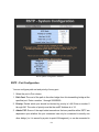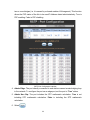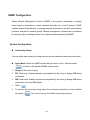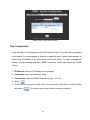
1
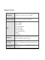
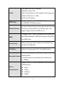
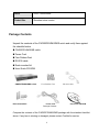
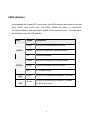
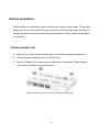
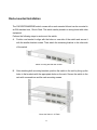
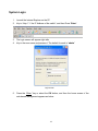
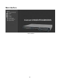
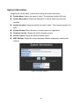
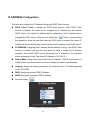
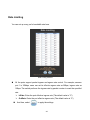
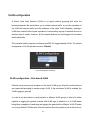
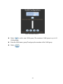
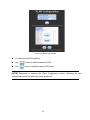
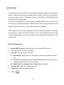
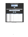
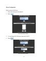
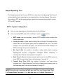
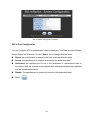
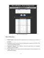
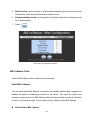
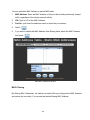
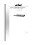
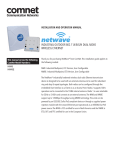
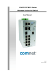
INSTALLATION AND OPERATION MANUAL
CWGE2FE24MODMS
MODULAR 26 PORT MANAGED ETHERNET SWITCH WITH UP TO
24-PORT 10/100T(X) OR 100FX AND 2-PORT 10/100/1000T(X) OR 1000FX
V1.03 – May 2011
The ComNet™ CWGE2FE24MODMS Managed Ethernet Switch chassis provides up to twenty-six ports of Ethernet
connectivity through the use of three eight-port expansion modules and two rear-mounted fixed combo ports. This
Ethernet switch is easily configurable by selecting, sold separately, eight port modules that allow for all copper, or
all optical with SFP modules making the CWGE2FE24MODMS switch available for use with either conventional UTP
copper or fiber media. The twenty-four modular ports support the 10/100 Mbps electrical or 100Mbps optical
Ethernet IEEE 802.3 protocol. Auto-negotiating and auto-MDI/MDIX features are provided for simplicity and ease of
installation on electrical ports. Two additional ports are Gigabit combo SFP ports. These network managed layer 2
switches are optically and electrically compatible with IEEE 802.3 compliant Ethernet devices. Plug-and-play
design ensures ease of installation, and no electrical or optical adjustments are ever required. The
CWGE2FE24MODMS incorporates LED indicators for monitoring the operating status of the managed switch and
network. These units are rack mountable. The CWGE2FE24MODMS and its corresponding modules are designed
for installation in benign (0º – +45º C) operating environments.
Contents
1. INTRODUCTION....................................................................................................... 1
Features ............................................................................................................................. 2
Software Features.............................................................................................................. 3
Package Contents.............................................................................................................. 5
Ethernet Switching Technology.......................................................................................... 6
2. HARDWARE DESCRIPTION ................................................................................... 7
Physical Dimension............................................................................................................ 7
Front Panel......................................................................................................................... 7
LED Indicators.................................................................................................................... 8
Rear Panel ......................................................................................................................... 9
Desktop Installation.......................................................................................................... 10
Attaching Rubber Feet .............................................................................................. 10
Rack-mounted Installation................................................................................................ 11
Power On ......................................................................................................................... 12
3. NETWORK APPLICATION .................................................................................... 13
Connecting to the Switch ................................................................................................. 14
4. CONSOLE MANAGEMENT ................................................................................... 15
Login in the Console Interface ......................................................................................... 15
Module Hot-Swapping............................................................................................... 16
5. WEB-BASED MANAGEMENT............................................................................... 17
About Web-based Management ...................................................................................... 17
Preparing for Web Management ...................................................................................... 17
System Login ................................................................................................................... 18
Main interface................................................................................................................... 19
Main interface................................................................................................................... 19
System Information .......................................................................................................... 20
IP ADDRESS Configuration ............................................................................................. 21
DHCP Server – System configuration.............................................................................. 22
DHCP Client – System Configuration .............................................................................. 23
DHCP Server - Port and IP ADDRESS Bindings ............................................................. 23
TFTP - Update Firmware ................................................................................................. 24
TFTP – Restore Configuration ......................................................................................... 25
TFTP - Backup Configuration........................................................................................... 25
System Event Log – Syslog Configuration....................................................................... 26
System Event Log - SMTP Configuration ........................................................................ 27
System Event Log - Event Configuration ......................................................................... 29
SNTP Configuration ......................................................................................................... 31
IP Address Security.......................................................................................................... 33
User Authentication.......................................................................................................... 34
Advanced Configuration-Broadcast Storm Filter.............................................................. 35
Advanced Configuration-Aging Time ............................................................................... 36
Advanced Configuration-Jumbo Frame ........................................................................... 37
1000TX Cable Length ...................................................................................................... 38
Port Statistics ................................................................................................................... 39
Port Control ...................................................................................................................... 39
Port Trunk ........................................................................................................................ 41
Aggregator setting..................................................................................................... 41
Aggregator Information ............................................................................................. 43
State Activity ............................................................................................................. 44
Port Mirroring ................................................................................................................... 45
Rate Limiting .................................................................................................................... 46
VLAN configuration .......................................................................................................... 47
VLAN configuration - Port-based VLAN.................................................................... 47
802.1Q VLAN............................................................................................................ 50
802.1Q Configuration......................................................................................... 50
Group Configuration .......................................................................................... 52
Rapid Spanning Tree ....................................................................................................... 53
RSTP - System Configuration................................................................................... 53
RSTP - Port Configuration ........................................................................................ 54
SNMP Configuration ........................................................................................................ 56
System Configuration................................................................................................ 56
Trap Configuration .................................................................................................... 57
SNMPV3 Configuration............................................................................................. 58
Context Table ............................................................................................. 58
User Profile................................................................................................. 58
Group Table................................................................................................ 59
Access Table .............................................................................................. 59
MIB view Table ........................................................................................... 60
QoS Configuration............................................................................................................ 60
IGMP Configuration.......................................................................................................... 63
802.1X/Radius Configuration .................................................................................... 65
System Configuration ........................................................................................ 65
802.1x Port Configuration .................................................................................. 66
Misc Configuration ............................................................................................. 67
MAC Address Table.................................................................................................. 68
Static MAC Address........................................................................................... 68
MAC Filtering ..................................................................................................... 69
All MAC Addresses............................................................................................ 70
Access Control List .......................................................................................................... 71
Factory Default................................................................................................................. 72
Save Configuration........................................................................................................... 73
System Reboot................................................................................................................. 73
6. PROBLEM SOLVING ............................................................................................. 74
Incorrect connections ....................................................................................................... 74
Faulty or loose cables ............................................................................................ 74
Non-standard cables.............................................................................................. 74
Improper Network Topologies................................................................................ 74
Diagnosing LED Indicators............................................................................................... 75
Cabling................................................................................................................... 75
7. TECHNICAL SPECIFICATION............................................................................... 76
1. Introduction
The CWGE2FE24MODMS 26 Port Combo Managed Switch is a modular switch that can
be used to build high-performance switched workgroup networks. This switch is a
store-and-forward device that offers low latency for high-speed networking. The Switch is
targeted at workgroup, department or backbone computing environments.
The CWGE2FE24MODMS 26 Port Combo Managed Switch features a “store-and-forward”
switching scheme. This allows the switch to auto-learn and store source Address in an
8K-entry MAC Address table.
MDI (Medium Dependent Interface) Port is also called an "uplink port". The MDI port does
not cross transmit and receive lines that is done by the regular ports (MDI-X ports) that
connect to the end stations. In general, MDI means connecting to another Hub or Switch
while MDIX means connecting to a workstation or PC. Therefore, Auto MDI/MDIX means
that you can connect to another Switch or workstation without changing non-crossover or
crossover cabling.
The CWGE2FE24MODMS 26 Port Combo Managed Switch has 3-module slots. The user
can purchase the modules in accordance with their needs that give flexibility on network
applications.
1
Features
Conforms to IEEE802.3 10BASE-T, 802.3u 100BASE-TX/FX, 802.3ab 1000BASE-T,
802.3z Gigabit SX/LX
3 slots for 8 ports 10/100TX or 8 ports 100Mbps using SFP modules
IEEE802.3x Flow control
Flow control for full duplex
Backpressure for half duplex
High back-plane bandwidth 8.8Gbps
Supports IEEE802.3ad Port trunk with LACP
Broadcast storm filter supported
IGMP supports for Multi Media application
Supports IEEE 802.1p class of service
Port security supported
Port bandwidth control supported
Supports IEEE 802.1d Spanning tree protocol
Supports GVRP function
Port Base VLAN/802.1Q VLAN supported
IEEE 802.1X user authentication
Supports DHCP client
Web/ SNMP / Telnet / CLI management
Optional Module for slot:
8 ports 10/100TX module
8 ports 100FX SFP module
2
Software Features
Management
SNMP v1/v2c/v3, Web, Telnet, CLI, RMON1
Software Upgrade
TFTP and Console firmware upgradeable
RFC 3418 SNMP MIB
RFC 1213 MIBII
RFC 2011 MIB
RFC 1493 Bridge MIB
MIB
RFC 2674 VLAN
RFC 1215 Trap MIB
RFC 1643 Ethernet like
RMON1
Private MIB
SNMP Trap
Cold/warm start trap, link down/link up trap, authorization
fail trap, fan fail trap. power event trap
Supports IEEE802.3ad with LACP function. Up to 13 trunk
Port Trunk
groups, trunk member up to 4 ports and include 2 uplink
ports
Spanning Tree
IEEE802.1d spanning tree, IEEE 802.1w Rapid Spanning
tree protocol
3
Port based VLAN, up to 24 groups
IEEE802.1Q Tag VLAN
VLAN
Static VLAN groups up to 256, Dynamic VLAN group up to
2048, VLAN ID from 1 to 4094.
GVRP up to 256 groups
QOS Policy
Port based, Tag based, IP ADDRESS v4 Type of service,
IP ADDRESS v4 Different service.
Per port 4 queues, High/ low queue. Service rule: first come
Class of Service
first service; all High before Low, WRR for High or low
weight. Weight round ratio (WRR): 8:4:2:1
It supports IGMP V1 and V2 snooping; IGMP Snooping for
IGMP
Multi-Media application, IGMP group supports 256 groups
and IGMP query
Port Security
Port Mirror
Support 50 entries of MAC Address for static MAC and
another 50 for MAC filter
Support 3 mirroring types: “RX, TX and Both packet”
Per port support ingress rate limiting and egress rate
Bandwidth Control
shaping control.
The rate limiting and rate shaping can be setting from
0~100Mbps
Support IEEE802.1x User-Authentication and can report to
RADIUS server.
802.1x
Reject
Authentication
Accept
Authorize
Disable
4
DHCP
DHCP Client/Server
Packet filter
Broadcast storm control
Package Contents
Unpack the contents of the CWGE2FE24MODMS switch and verify them against
the checklist below.
CWGE2FE24MODMS switch
Power Cord
Four Rubber Feet
RS-232 cable
Rack-mounted kit
User Guide CD-ROM
CWGE2FE24MODMS switch
Rack-mounted Kit
Four Rubber Feet
Power Cord
RS-232 Cable
User Guide CD-ROM
Package Contents
Compare the contents of the CWGE2FE24MODMS package with the standard checklist
above. If any item is missing or damaged, please contact ComNet for service.
5
Ethernet Switching Technology
Ethernet Switching Technology dramatically boosted the usable total bandwidth of a
network, eliminated congestion problems inherent with CSMA/CD (Carrier Sense multIP
Address le access with Collision Detection) protocol, and greatly reduced unnecessary
transmission.
This revolutionized networking. First, by allowing two-way simultaneous transmission over
the same port (Full-duplex), it essentially doubled the bandwidth. Second, by reducing the
collision domain to a single switch-port eliminated the need for carrier sensing. Third, by
using the store-and-forward technology’s approach of inspecting each packet to intercept
corrupt or redundant data eliminated unnecessary transmission that slows the network. By
employing Address learning it replaced the inefficient receiving port.
Auto-negotiation regulates the speed and duplex operation of each port, based on the
capability of both devices. Flow-control allows transmission from a 100Mbps node to a
10Mbps node without any loss of data. Auto-negotiation and flow-control may require
disablement for some networking operations involving legacy equipment. Disabling the
auto-negotiation is accomplished by fixing the speed or duplex operation of a port.
Ethernet Switching Technology supplied higher performance at costs lower than other
solutions. Wider bandwidth, no congestion, and the reduction in traffic is why switching is
replacing expensive routers and inefficient hubs as the ultimate networking solution.
Switching brought a whole new way of thinking to networking.
6
2. Hardware Description
This section describes the hardware of the CWGE2FE24MODMS switch, and gives a
physical and functional overview of the switch.
Physical Dimension
The CWGE2FE24MODMS switch has a physical dimension of 440mm(W) x 280mm(D) x
44mm(H).
Front Panel
The Front Panel of the CWGE2FE24MODMS switch supports 2 kinds of port modules.
Please refer to the module user guide for further information.
7
LED Indicators
Accompanying the Copper/SFP combo ports, four LED indicators are located on the rear
panel beside each combo port. The LEDs indicate the status of Link/Activity,
Full-Duplex/Collision, and transmission speed for the respective ports. The table below
gives definition for each LED indicator.
LED
LK/ACT
FD/COL
1000
100
Status
Description
Green
The port is connecting with the device.
Blinks
The port is receiving or transmitting data.
Off
No device attached.
Yellow
The port is operating in Full-duplex mode.
Blinks
Collision of Packets occurs in the port.
Off
In half-duplex mode
Green
The port is operating at the speed of 1000Mbps
Green
The port is operating at the speed of 100Mbps
(for RJ-45 port only)
The Description of LED Indicators
8
Rear Panel
The 3-pronged power plug, 2 fans, DC power input, 2 Gigabit Copper/SFP combo port,
and one RS-232 console port are located at the rear Panel of the CWGE2FE24MODMS
switch as shown in Figure 2-1. The Switch will work with AC power in the range of
100-240V AC, 50-60Hz.
The Rear Panel of the CWGE2FE24MODMS switch
9
Desktop Installation
Set the switch on a sufficiently large flat space with a power outlet nearby. The surface
where you put your switch should be clean, smooth, level and sturdy. Make sure there is
enough clearance around the switch to allow attachment of cables, power cord and allow
air circulation.
Attaching Rubber Feet
A.
Make sure mounting surface on the bottom of the Switch is grease and dust free.
B.
Remove adhesive backing from your Rubber Feet.
C.
Apply the Rubber Feet to each corner on the bottom of the switch. These footpads
can prevent the switch from shock/vibration.
Attaching Rubber Feet to each corner on the bottom of the Switch
10
Rack-mounted Installation
The CWGE2FE24MODMS switch comes with a rack-mounted kit and can be mounted in
an EIA standard size, 19-inch Rack. The switch can be placed in a wiring closet with other
equipment.
Perform the following steps to rack mount the switch:
A.
Position one bracket to align with the holes on one side of the switch and secure it
with the smaller bracket screws. Then attach the remaining bracket to the other side
of the switch.
Attach mounting brackets with screws
B.
After attaching both mounting brackets, position the switch in the rack by lining up the
holes in the brackets with the appropriate holes on the rack. Secure the switch to the
rack with a screwdriver and the rack-mounting screws.
Mount the Switch in 19” Rack
11
Note: For proper ventilation, allow about at least 4 inches (10 cm) of clearance on the
front and 3.4 inches (8 cm) on the back of the switch. This is especially important for
enclosed rack installation.
Power On
Connect the power cord to the power socket on the rear panel of the switch. The other
side of power cord connects to the power outlet. The internal power supply of the switch
works with voltage range of AC in the 100-240VAC, frequency 50~60Hz. Check the power
indicator on the front panel to see if power is properly supplied.
12
3. Network Application
This section provides you a few samples of network topology in which the switch is used.
In general, the CWGE2FE24MODMS switch is designed as a segment switch. That is,
with its large Address table (8000 MAC Address) and high performance, it is ideal for
interconnecting networking segments.
Personal computers, workstations and servers can communicate each other by directly
connecting with CWGE2FE24MODMS switch. The switch automatically learns nodes
Addresses, that are subsequently used to filter and forward all traffic based on the
destination Address.
By using the Gigabit copper/SFP combo port (on the rear side of the switch), 10/100Mbps
copper, or Ethernet Fiber port the switch can connect with another switch or hub to
interconnect other small-switched workgroups to form a larger switched network.
Meanwhile, you can also use Ethernet or fiber ports to connect switches. The following
figure is an example of the CWGE2FE24MODMS switch application topology.
The example of application topology
13
Connecting to the Switch
The Console port is a female DB-9 connector that enables a connection to a PC or
terminal for monitoring and configuring the Switch. Use the supplied RS-232 cable with a
male DB-9 connector to connect a terminal or PC to the Console port.
The Console configuration (out of band) allows you to set the switch for remote terminal
as if the console terminal were directly connected to it.
14
4. Console Management
Login in the Console Interface
When the connection between switch and PC is established, turn on the PC and run a
terminal emulation program or Hyper Terminal and configure its communication
parameters to match the following default characteristics of the console port:
Baud Rate: 9600 bps
Data Bits: 8
Parity: none
Stop Bit: 1
Control flow: None
The settings of communication parameters
After finishing the parameter settings, select “OK“. When the blank screen shows up,
press Enter key to bring out the login prompt. Key in “admin“ (default value) for the both
Username and Password (use Enter key to switch), then press Enter key and the Main
Menu of console management appears. Please see below figure for login screen.
15
Console login screen
Module Hot-Swapping
The CWGE2FE24MODMS 26 Port Combo Managed Switch supports module
interchanging. The user can insert or pull the module out of the slot without powering
down the switch. Once the module is fully inserted, the LEDs on the module panel will all
light on at the same time. Meanwhile, the switch also sends warning message to the
connected PC, workstation or terminal via the console port. Please note the illustration
below for reference.
Warning message interface
16
5. Web-Based Management
This section introduces the configuration and functions of the Web-Based management.
About Web-based Management
Inside the CPU board of the switch, there exists an embedded HTML website residing in
flash memory. It offers advanced management features and allows users to manage the
switch from anywhere on the network through a standard browser such as Microsoft
Internet Explorer.
The Web-Based Management supports Internet Explorer 6.0. It is based on Java Applets
with an aim to reduce network bandwidth consumption, enhance access speed and
present an easy viewing screen.
Preparing for Web Management
Before using web management, you can use the console port to login to the switch and
checking the default IP ADDRESS of the Switch. Please refer to Console Management
Chapter for console login. If you need change the IP Address the first use, you can use
console mode to modify it. The default value is as below:
IP ADDRESS: 192.168.10.1
Subnet Mask: 255.255.255.0
Default Gateway: 192.168.10.254
User Name: admin Password: admin
17
System Login
1.
Launch the Internet Explorer on the PC
2.
Key in “http:// “+” the IP Address of the switch”, and then Press “Enter”.
3.
The login screen will appear right after
4.
Key in the user name and password. The default for each is “admin”
Login screen
5.
Press the “Enter” key or select the OK button, and then the home screen of the
web-based management appears as below:
18
Main interface
Main interface
19
System Information
Assigning the system name, location and viewing the system information
System Name: Assign the name of switch. The maximum length is 64 bytes
System Description: Display the description of switch. Read-only cannot be
modified
System Location: Assign the switch’s physical location. The maximum length is 64
bytes
System Contact: Enter the name of contact person or organization
Firmware Version: Display the switch’s firmware version
Kernel Version: Display the kernel software version
MAC Address: Display the unique hardware Address assigned by manufacturer
(default)
System information interface
20
IP ADDRESS Configuration
The user can configure the IP Address Settings and DHCP client function
DHCP Client: Enable or disable the DHCP client function. When DHCP client
function is enabled, the switch will be assigned an IP Address from the network
DHCP server. The default IP Address will be replaced by the IP Address that is
assigned by DHCP server. After the user selects the
button, a popup dialog
box appears to inform the user that when the DHCP client is enabled, the current IP
Address will be lost and the user should find the new IP Address on the DHCP server.
IP ADDRESS: Assigning the IP Address that the network is using. If the DHCP client
function is enabled, and then the user does not need to assign the IP Address
manually. The network DHCP server will assign the IP Address for the industrial
switch and display it here. The default IP Address is 192.168.10.1
Subnet Mask: Assign the subnet mask of the IP Address. If DHCP client function is
enabled, then user the user does not need to assign the subnet mask manually.
Gateway: Assign the network gateway for the industrial switch. The default gateway
is 192.168.10.254
DNS1: Assign the primary DNS IP Address
DNS2: Assign the secondary DNS IP Address
And then, select
IP ADDRESS configuration interface
21
DHCP Server – System configuration
The system provides the DHCP server function. By enabling the DHCP server function,
the switch system will be the DHCP server.
DHCP Server: Enable or Disable the DHCP Server function. Enable – the switch will
be the DHCP server on your local network.
Low IP ADDRESS: the dynamic IP Address assignment range. Lowest IP Address is
the beginning of the dynamic IP Address assigns range. For example: dynamic IP
Address assignment range is from 192.168.1.100 ~ 192.168.1.200. 192.168.1.100
will be the lowest IP Address.
Highest IP ADDRESS: the dynamic IP Address assignment range. The highest IP
Address is the end of the dynamic IP Address assignment range. For example:
dynamic IP Address assignment range is from 192.168.1.100 ~ 192.168.1.200.
192.168.1.200 will be the highest IP Address.
Subnet Mask: the dynamic IP Address assignment range subnet mask.
Gateway: the gateway in your network.
DNS: Domain Name Server IP Address in your network.
Lease Time (sec): It is the time period that system will reset the dynamic IP Address
assignment to ensure the dynamic IP Address will not been occupied for a long time
or the server does not know that the dynamic IP Address is idle.
And then, select
22
DHCP Server Configuration interface
DHCP Client – System Configuration
When the DHCP server function is active, the system will collect the DHCP client
information and display in here.
DHCP Client Entries interface
DHCP Server - Port and IP ADDRESS Bindings
You can assign the specific IP Address that is one of the IP Addresses in dynamic IP
Address pool to the specific port. When the device is connected to the port and asks for
dynamic IP address assignment, the system will assign the IP Address that had been
assigned before to the connected device.
23
Port and IP ADDRESS Bindings interface
TFTP - Update Firmware
The functions allow a user to update the switch firmware. Before updating, make sure you
have your TFTP server ready; and the firmware image is on the TFTP server.
1.
TFTP Server IP Address: fill in your TFTP server IP Address.
2.
Firmware File Name: the name of firmware image.
3.
Select
.
Update Firmware interface
24
TFTP – Restore Configuration
You can restore the EEPROM value of the switch from the TFTP server. Before doing this,
you must have a prior backup of the configuration in the TFTP server then the switch can
restore the backup file to its EEPROM.
1.
TFTP Server IP Address: fill in the TFTP server IP Address.
2.
Restore File Name: fill in the correct restore file name.
3.
Select
.
Restore Configuration interface
TFTP - Backup Configuration
You can save the current EEPROM value from the switch to TFTP server for restoring
again afterward.
1.
TFTP Server IP Address: fill in the TFTP server IP Address.
2.
Backup File Name: fill in the file name
3.
Select
.
25
Backup Configuration interface
System Event Log – Syslog Configuration
Configure the system event mode, that you want to collect, and system log server IP ADDRESS.
1.
Syslog Client Mode: select the system log mode – client only, server only, or both
S/C.
2.
System Log Server IP Address: assigned the system log server IP Address.
3.
Select
4.
Select
5.
to refresh the events log.
to clear all current events log.
After configuring, Select
.
26
Syslog Configuration interface
System Event Log - SMTP Configuration
You can set up the mail server IP Address, Email account, account password, and
forwarded Email account for receiving the event alert.
1.
Email Alert: enable or disable the Email alert function.
2.
SMTP Server IP Address: set up the mail server IP Address (when Email Alert
enabled, this function will then be available).
3.
Authentication: mark the check box to enable and configure the Email account and
password for authentication (when Email Alert enabled, this function will then be
available).
4.
Mail
Account:
set
up
the
Email
27
account
to
receive
the
alert
(e.g.
[email protected]). It must be an existing Email account on the mail server that you
had set up in SMTP Server IP Address column.
5.
Password: The Email account password.
6.
Confirm Password: reconfirm the password.
7.
Receipt e-mail Address 1 ~ 6: you can assign up to 6 Email accounts also to
receive the alert.
8.
Select
.
SMTP Configuration interface
28
System Event Log - Event Configuration
You can select the system log events and SMTP events. When selected events occur, the
system will send out the log information. Also, per port log and SMTP events can be
selected. After configure, Select
.
System event selection: 4 selections – Device cold start, Device warm start, SNMP
Authentication Failure, and X-ring topology change. Mark the checkbox to select the
event. When selected events occur, the system will issue the logs.
Device warm start: when the device executes warm start, the system will issue
a log event.
Authentication Failure: when the SNMP authentication fails, the system will
issue a log event.
Port event selection: select the per port events and per port SMTP events. It has 3
selections – Link UP, Link Down, and Link UP & Link Down. Disable means no event
is selected.
Link UP: the system will issue a log message when the port connection is up
only.
Link Down: the system will issue a log message when the port connection is
down only.
Link UP & Link Down: the system will issue a log message when the port
connection is up and down.
29
Event Configuration interface
30
SNTP Configuration
You can configure the SNTP (Simple Network Time Protocol) settings. The SNTP allows
you to synchronize switch clocks with the Internet.
1.
SNTP Client: enable or disable SNTP function to get the time from the SNTP server.
2.
Daylight Saving Time: enable or disable daylight saving time function. When
daylight saving time is enabled, you need to configure the daylight saving time period.
3.
UTC Time zone: set the switch location time zone. The following table lists the
different location time zone for your reference.
Local Time Zone
Conversion from UTC Time at 12:00 UTC
November Time Zone
- 1 hour
11am
Oscar Time Zone
-2 hours
10 am
ADT - Atlantic Daylight
-3 hours
9 am
-4 hours
8 am
-5 hours
7 am
-6 hours
6 am
-7 hours
5 am
-8 hours
4 am
ALA - Alaskan Standard
-9 hours
3 am
HAW - Hawaiian Standard
-10 hours
2 am
AST - Atlantic Standard
EDT - Eastern Daylight
EST - Eastern Standard
CDT - Central Daylight
CST - Central Standard
MDT - Mountain Daylight
MST - Mountain Standard
PDT - Pacific Daylight
PST - Pacific Standard
ADT - Alaskan Daylight
31
Nome, Alaska
-11 hours
1 am
+1 hour
1 pm
+2 hours
2 pm
BT - Baghdad, USSR Zone 2
+3 hours
3 pm
ZP4 - USSR Zone 3
+4 hours
4 pm
ZP5 - USSR Zone 4
+5 hours
5 pm
ZP6 - USSR Zone 5
+6 hours
6 pm
+7 hours
7 pm
+8 hours
8 pm
+9 hours
9 pm
+10 hours
10 pm
+12 hours
Midnight
CET - Central European
FWT - French Winter
MET - Middle European
MEWT - Middle European
Winter
SWT - Swedish Winter EET - Eastern European,
USSR Zone 1
WAST - West Australian
Standard
CCT - China Coast, USSR
Zone 7
JST - Japan Standard, USSR
Zone 8
EAST - East Australian
Standard GST
Guam Standard, USSR Zone
9 IDLE - International Date Line
NZST - New Zealand
Standard
NZT - New Zealand 4.
SNTP Sever URL: set the SNTP server IP Address.
5.
Daylight Saving Period: set up the Daylight Saving time beginning date and
Daylight Saving time ending date. Both will be different every year.
32
6.
Daylight Saving Offset (mins): set up the offset time.
7.
Switch Timer: display the switch current time.
8.
Select
.
SNTP Configuration interface
IP Address Security
IP Address security function allows user to assign 10 specific IP Addresses that have
permission to access the switch through the web browser for securing switch
management.
IP ADDRESS Security Mode: When this option is in Enable mode, the Enable
HTTP Server and Enable Telnet Server check boxes will then be available.
Enable HTTP Server: When this check box is checked, the IP Addresses among
Security IP ADDRESS 1 ~ IP ADDRESS 10 will be allowed to access via HTTP
service.
Enable Telnet Server: When checked, the IP Addresses among the Security IP
ADDRESS 1 ~ IP ADDRESS 10 will be allowed to access via Telnet service.
Security IP ADDRESS 1 ~ 10: Assign up to 10 specific IP Addresses. Only these 10
33
IP Addresses can access and manage the switch through the Web browser
And then, select
button to apply the configuration
[NOTE] Remember to execute the “Save Configuration” action, otherwise the new
configuration will lose when switch powers off.
IP ADDRESS Security interface
User Authentication
Change web management login user name and password for the management security
issue
1.
User name: Key in the new user name (The default is “admin”)
2.
Password: Key in the new password (The default is “admin”)
3.
Confirm password: Re-type the new password
4.
And then, select
34
User Authentication interface
Advanced Configuration-Broadcast Storm Filter
This page enables user to select the filter packet type. All the packet types filtering
conditions could be selected at the same time.
1.
Flooded Unicast/Multicast Packets: When this check box is marked, the switch will
filter the packet type of Flooded Unicast/Multicast.
2.
Control Packets: When this check box is marked, the switch will filter the packet
type of Control.
3.
IP Address Multicast Packets: When this check box is marked, the switch will filter
the packet type of IP Address Multicast.
4.
Broadcast Packets: When this check box is marked, the switch will filter the packet
type of Flooded Unicast/Multicast.
5.
Broadcast Storm Rate: User can set the filtering rate range from 1/2 of ingress to
1/16 of ingress.
6.
And then, select
35
Broadcast Storm Filter
Advanced Configuration-Aging Time
This tab is used to assign the aging time of MAC table.
Aging Time of MAC Table: Select the aging time as OFF, 150 sec, 300 sec, or 600
sec. When MAC table is not used within the aging time, the MAC Address table will
then be cleared.
Auto Flush MAC Table When Link Down: When this item is enabled, the switch will
flush its MAC Address table when link down.
Select
button to make the setting effective.
Aging Time Setting
36
Advanced Configuration-Jumbo Frame
This tab is used to enable the jumbo frame function.
Enable Jumbo Frame: When this item is marked, the Gigabit port of the switch (on
the rear panel) extends the frame to 9022bytes.
Select
button to make the setting effective.
Jumbo Frame Setting
37
1000TX Cable Length
This tab is used to allow port 25 and port 26 to support Cat5e or Cat6 cable length longer
than 10 meters.
To support long cable: Uncheck the check box for the port(s) you would like to
effect.
And then, click
to have the configuration taken effect.
Jumbo Frame interface
38
Port Statistics
The following information provides the current port statistic information
Select
button to clean all counts
Port Statistics interface
Port Control
In Port control, you can view every port status that depended on user setting and the
negotiation result.
1.
Port: select the port that you want to configure.
2.
State: Current port status. The port can be set to disable or enable mode. If the port
39
setting is disable then will not receive or transmit any packet.
3.
Negotiation: set auto negotiation status of port.
4.
Speed: set the port link speed.
5.
Duplex: set full-duplex or half-duplex mode of the port.
6.
Flow Control: set flow control function as Symmetric or Asymmetric in Full Duplex
mode. The default value is Disable.
7.
Security: When its state is “On”, it means this port accepts only one MAC Address .
8.
Select
.
Port Control interface
40
Port Trunk
The Link Aggregation Control Protocol (LACP) provides a standardized means for
exchanging information between Partner Systems on a link to allow their Link Aggregation
Control instances to reach agreement on the identity of the Link Aggregation Group to
which the link belongs, move the link to that Link Aggregation Group, and enable its
transmission and reception functions in an orderly manner. Link aggregation lets you
group up to seven consecutive ports into two dedicated connections. This feature can
expand bandwidth to a device on the network. LACP operation requires full-duplex
mode, more detail information refers to IEEE 802.3ad.
Aggregator setting
1.
System Priority: a value used to identify the active LACP. The switch with the lowest
value has the highest priority and is selected as the active LACP.
2.
Group ID: There are three trunk groups to provide configure. Choose the "Group ID"
and select
3.
.
LACP: If enable, the group is LACP static trunk group. If disable, the group is local
static trunk group. All ports support LACP dynamic trunk group. If connecting to the
device that also supports LACP, the LACP dynamic trunk group will be created
automatically.
4.
Work ports: allow max four ports can be aggregated at the same time. With LACP
static trunk group, the exceed ports are standby and can be aggregated if work ports
fail. If it is local static trunk group, the number of ports must be the same as the group
member ports.
5.
6.
Select the ports to join the trunk group. Allow max four ports can be aggregated at the
same time. Select
button to add the port. To remove unwanted ports, select
the port and select
button.
If LACP enabled, you can configure LACP Active/Passive status in each ports on
41
State Activity page.
7.
Select
8.
Use
.
button to delete Trunk Group. Select the Group ID and select
button.
Port Trunk—Aggregator Setting interface
42
Aggregator Information
When you have set the LACP aggregator, you will see the related information here.
Port Trunk – Aggregator Information interface
43
State Activity
When you have set up the LACP aggregator, you can configure port state activity. You
can mark or un-mark the port. When you mark the port and select
button the
port state activity will change to Active. Opposite is Passive.
Active: The port automatically sends LACP protocol packets.
Passive: The port does not automatically send LACP protocol packets, and responds
only if it receives LACP protocol packets from the opposite device.
[NOTE]
1. A link having either two active LACP ports or one active port can perform dynamic
LACP trunk.
2. A link that has two passive LACP ports will not perform dynamic LACP trunk
because both ports are waiting for an LACP protocol packet from the opposite
device.
3. If you are the active LACP’s actor, after you have selected trunk port, the active
status will be created automatically.
Port Trunk – State Activity interface
44
Port Mirroring
The Port mirroring is a method for monitoring traffic in switched networks. Traffic through
ports can be monitored by one specific port. That means traffic goes in or out monitored
(source) ports and will be duplicated into an analysis (mirror) port.
Mode: Select the mirroring mode by pulling down the selection item menu: RX, TX or
Both RX ⁄ TX.
Analysis Port: Select one port to be the analysis (mirror) port for monitoring RX only,
TX only or both RX and TX traffic that comes from source port. User can connect
analysis port to LAN analyzer or Nextray
Monitored Port: The ports that user wants to monitor. All monitored port traffic will be
copied to an analysis (mirror) port. The user can select one monitored port by pulling
down the selection item menu.
And then, select
button.
Port Trunk – Port Mirroring interface
45
Rate Limiting
You can set up every port’s bandwidth rate here.
Rate Limiting interface
All the ports support packet ingress and egress rate control. For example, assume
port 1 is 10Mbps, users can set its effective egress rate as 2Mbps, ingress rate as
1Mbps. The switch performs the ingress rate by packet counter to meet the specified
rate
InRate: Enter the port effective ingress rate (The default value is “0”)
OutRate: Enter the port effective egress rate (The default value is “0”)
And then, select
to apply the settings
46
VLAN configuration
A Virtual Local Area Network (VLAN) is a logical network grouping that limits the
broadcast domain that would allow you to isolate network traffic, so only the members of
the VLAN will receive traffic from the members of the same VLAN. Basically, creating a
VLAN from a switch is the logical equivalent of reconnecting a group of network devices to
another Layer 2 switch. However, all the network devices are still plugged into the same
switch physically.
The industrial switch supports port-based and 802.1Q (tagged-based) VLAN. The default
configuration of VLAN operation mode is “Disable”.
VLAN Configuration interface
VLAN configuration - Port-based VLAN
Packets can go among only members of the same VLAN group. Note all unselected ports
are treated as belonging to another single VLAN. If the port-based VLAN is enabled, the
VLAN-tagging is ignored.
In order for an end station to send packets to different VLAN groups, it has to be either
capable of tagging the packets it sends with VLAN tags or attaches it to a VLAN-aware
bridge that is capable of classifying and tagging the packet with a different VLAN ID based
on not only default PVID but also other information about the packet, such as the protocol.
47
VLAN – Port Based interface
Select
to add a new VLAN group (The maximum VLAN group is up to 64
VLAN groups)
Enter the VLAN name, group ID and group the members of the VLAN group
Select
48
VLAN—Port Based Add interface
You will see the VLAN displays.
Use
Use
button to delete unwanted VLAN.
button to modify existing VLAN group.
[NOTE] Remember to execute the “Save Configuration” action, otherwise the new
configuration will be lost when the switch powers off.
49
802.1Q VLAN
Tagged-based VLAN is an IEEE 802.1Q specification standard. Therefore, it is possible to
create a VLAN across devices from different switch venders. IEEE 802.1Q VLAN uses a
technique to insert a “tag” into the Ethernet frames. Tag contains a VLAN Identifier (VID)
that indicates the VLAN numbers.
You can create Tag-based VLAN, and enable or disable GVRP protocol. There are 256
VLAN groups to provide configuration. Enable 802.1Q VLAN, the all ports on the switch
belong to default VLAN, VID is 1. The default VLAN can’t be deleted.
GVRP allows automatic VLAN configuration between the switch and nodes. If the switch
is connected to a device with GVRP enabled, you can send a GVRP request using the
VID of a VLAN defined on the switch; the switch will automatically add that device to the
existing VLAN.
802.1Q Configuration
1.
Enable GVRP Protocol: check the check box to enable GVRP protocol.
2.
Select the port that you want to configure.
3.
Link Type: there are 3 types of link type.
Access Link: single switch only, allow user to group ports by setting the same
VID.
Trunk Link: extended application of Access Link, allow user to group ports by
setting the same VID with 2 or more switches.
Hybrid Link: Both Access Link and Trunk Link are available.
4.
Untagged VID: assign the untagged frame VID.
5.
Tagged VID: assign the tagged frame VID.
6.
Select
50
802.1q VLAN interface
51
Group Configuration
Edit the existing VLAN Group.
1.
Select the VLAN group in the table list.
2.
Select
Group Configuration interface
3.
You can Change the VLAN group name and VLAN ID.
4.
Select
.
Group Configuration interface
52
Rapid Spanning Tree
The Rapid Spanning Tree Protocol (RSTP) is an evolution of the Spanning Tree Protocol
and provides for faster spanning tree convergence after a topology change. The system
also supports STP and the system will auto detect the connected device that is running
STP or RSTP protocol.
RSTP - System Configuration
User can view spanning tree information about the Root Bridge
User can modify RSTP state. After modification, select
button
RSTP mode: user must enable or disable RSTP function before configure the
related parameters
Priority (0-61440): a value used to identify the root bridge. The bridge with the
lowest value has the highest priority and is selected as the root. If the value
changes, user must reboot the switch. The value must be multIP Address le of
4096 according to the protocol standard rule
Max Age (6-40): the number of seconds a bridge waits without receiving
Spanning-tree
Protocol
configuration
messages
before
attempting
a
reconfiguration. Enter a value between 6 through 40
Hello Time (1-10): the time that controls switch sends out the BPDU packet to
check RSTP current status. Enter a value between 1 through 10
Forward Delay Time (4-30): the number of seconds a port waits before
changing from its Rapid Spanning-Tree Protocol learning and listening states to
the forwarding state. Enter a value between 4 through 30
[NOTE] Follow the rule to configure the MAX Age, Hello Time, and Forward Delay Time.
2 x (Forward Delay Time value –1) > = Max Age value >= 2 x (Hello Time value +1)
53
RSTP System Configuration interface
RSTP - Port Configuration
You can configure path cost and priority of every port.
1. Select the port in Port column.
1. Path Cost: The cost of the path to the other bridge from this transmitting bridge at the
specified port. Enter a number 1 through 200000000.
2. Priority: Decide which port should be blocked by priority in LAN. Enter a number 0
through 240. The value of priority must be the multIP Address le of 16.
3. Admin P2P: Some of the rapid state transactions that are possible within RSTP are
dependent upon whether the port concerned can only be connected to exactly one
other bridge (i.e. it is served by a point-to-point LAN segment), or can be connected to
54
two or more bridges (i.e. it is served by a shared medium LAN segment). This function
allows the P2P status of the link to be manIP Address ulated administratively. True is
P2P enabling. False is P2P disabling.
RSTP Port Configuration interface
4. Admin Edge: The port directly connected to end stations cannot create bridging loop
in the network. To configure the port as an edge port, set the port to “True” status.
5. Admin Non Stp: The port includes the STP mathematic calculation. True is not
including STP mathematic calculation. False is including the STP mathematic
calculation.
6. Select
.
55
SNMP Configuration
Simple Network Management Protocol (SNMP) is the protocol developed to manage
nodes (servers, workstations, routers, switches and hubs etc.) on an IP network. SNMP
enables network administrators to manage network performance, find and solve network
problems, and plan for network growth. Network management systems learn of problems
by receiving traps or change notices from network devices implementing SNMP.
System Configuration
Community Strings
You can define new community string sets and remove unwanted community string sets.
Agent Mode: Select the SNMP version that you want to use it. And then select
to switch to the selected SNMP version mode.
1.
String: fill the name of string.
2.
RO: Read only. Enables requests accompanied by this string to display MIB-object
information.
3.
RW: Read write. Enables requests accompanied by this string to display MIB-object
information and to set MIB objects.
1.
Select
2.
To remove the community string, select the community string that you have defined
and select
.
. You cannot remove the default community string set.
56
SNMP System Configuration interface
Trap Configuration
A trap manager is a management station that receives traps, the system alerts generated
by the switch. If no trap manager is defined, no traps will issue. Create a trap manager by
entering the IP Address of the station and a community string. To define management
stations as trap manager and enter SNMP community strings and selects the SNMP
version.
1. IP Address: enter the IP Address of trap manager.
2. Community: enter the community string.
3. Trap Version: select the SNMP trap version type – v1 or v2.
4. Select
.
5. To remove the community string, select the community string that you have defined
and select
. You cannot remove the default community string set.
57
Trap Managers interface
SNMPV3 Configuration
Configure the SNMP V3 function including Context Table, User Profile, Group Table,
Access Table and MIBView Table.
Context Table
Configure SNMP v3 context table. Assign the context name of context table. Select
to add context name. Select
to remove unwanted context name.
User Profile
Configure SNMP v3 user table..
User ID: set up the user name.
Authentication Password: set up the authentication password.
Privacy Password: set up the private password.
Select
Select
to add context name.
to remove unwanted context name.
58
SNMP V3 configuration interface
Group Table
Configure SNMP v3 group table.
Security Name (User ID): assign the user name that you have set up in user table.
Group Name: set up the group name.
Select
Select
to add context name.
to remove unwanted context name.
Access Table
Configure SNMP v3 access table.
Context Prefix: set up the context name.
Group Name: set up the group.
Security Level: select the access level.
59
Context Match Rule: select the context match rule.
Read View Name: set up the read view.
Write View Name: set up the write view.
Notify View Name: set up the notify view.
Select
Select
to add context name.
to remove unwanted context name.
MIB view Table
Configure MIB view table.
View Name: set up the name.
Sub-Oid Tree: fill the Sub OID.
Type: select the type – exclude or included.
Select
Select
to add context name.
to remove unwanted context name.
QoS Configuration
You can configure Qos mode, 802.1p priority [7-0] setting, Static Port Ingress Priority
setting and TOS setting.
Select the Qos Mode: Select the Qos policy rule
Disable QoS Priority: The default status of Qos Priority is disabled.
High Empty Then Low: When all the high priority packets are empty in queue,
low priority packets will be processed then.
Highest:SecHigh:SecLow:Lowest:8:4:2:1: The switch will follow 8:4:2:1 rate
to process priority queue from Highest to lowest queue.
Use an 8,4,2,1 weighted fair queuing scheme: The switch will follow 8:4:2:1 rate
60
to process priority queue from High to Lowest queue. For example, as the
system processes 1 frames of the lowest queue, 2 frames of the low queue, 4
frames of the middle queue, and 8 frames of the high queue will be processed at
the same time in accordance with the 8,4,2,1 policy rule.
Highest:SecHigh:SecLow:Lowest:15:7:3:1:
The
process
order
is
in
order
is
in
compliance with the transfer rate of 15:7:3:1.
Highest:SecHigh:SecLow:Lowest:15:10:5:1:
The
process
compliance with the transfer rate of 15:10:5:1.
802.1p priority [7-0]: Configure per priority level.
Priority 0 ~ 7: each priority has 4 priority levels – Highest, SecHigh, SecLow,
and Lowest.
Static Port Ingress Priority: The port ingress level is from 0 to 7.
TOS: the system provides 0~63 TOS priority level. Each level has 8 priorities – 0~7.
The default value is “0” priority for each level. When the IP Address packet is received,
the system will check the TOS level value in the IP Address packet that has received.
For example: user set the TOS level 25 is 0. The port 1 is following the TOS priority
policy only. When the port 1 packet received, the system will check the TOS value of
the received IP Address packet. If the TOS value of received IP Address packet is
25(priority = 0), and then the packet priority will have highest priority.
Select
.
61
QoS Configuration interface
62
IGMP Configuration
The Internet Group Management Protocol (IGMP) is an internal protocol of the Internet
Protocol (IP Address) suite. IP Address manages multicast traffic by using switches,
routers, and hosts that support IGMP. Enabling IGMP allows the ports to detect IGMP
queries and report packets and manage IP Address multicast traffic through the switch.
IGMP have three fundamental types of message as follows:
Message
Description
A message sent from the querier (IGMP router or switch) asking for a
Query
response from each host belonging to the multicast group.
A message sent by a host to the querier to indicate that the host wants to
Report
be or is a member of a given group indicated in the report message.
A message sent by a host to the querier to indicate that the host has quit
Leave Group
being a member of a specific multicast group.
The switch support IP Address multicast, you can enable IGMP protocol on web
management’s switch setting advanced page, then display the IGMP snooping
information.
IP
Address
multicast
addresses
range
from
224.0.0.0
through
239.255.255.255.
IGMP Protocol: enable or disable the IGMP protocol.
IGMP Query: Select the IGMP query function as Enable or Auto to set the switch as
a querier for IGMP version 2 multicast networks.
Select
.
63
IGMP Configuration interface
LLDP
LLDP (Link Layer Discovery Protocol) function allows the switch to advertise its information to
other nodes on the network and store the information it discovers.
LLDP Protocol: Disable or enable LLDP function.
LLDP Interval: Set the interval of learning the information time in second.
Select
.
LLDP Configuration interface
Security
In this section, you can configure 802.1x and MAC Address table.
64
802.1X/Radius Configuration
802.1x is an IEEE authentication specification that allows a client to connect to a wireless
access point or wired switch but prevents the client from gaining access to the Internet
until it provides authority, like a user name and password that are verified by a separate
server.
System Configuration
After enabling the IEEE 802.1X function, you can configure the parameters of this
function.
1.
IEEE 802.1x Protocol: enable or disable 802.1x protocol.
2.
Radius Server IP Address: set the Radius Server IP Address.
3.
Server Port: set the UDP destination port for authentication requests to the specified
Radius Server.
4.
Accounting Port: set the UDP destination port for accounting requests to the
specified Radius Server.
5.
Shared Key: set an encryption key for using during authentication sessions with the
specified radius server. This key must match the encryption key used on the Radius
Server.
6.
NAS, Identifier: set the identifier for the radius client.
7.
Select
.
65
802.1x System Configuration interface
802.1x Port Configuration
You can configure 802.1x authentication state for each port. The State provides Disable,
Accept, Reject and Authorize. Use the “Space” key to change the state value.
Reject: the specified port is required to be held in the unauthorized state.
Accept: the specified port is required to be held in the authorized state.
Authorized: the specified port is set to the authorized or unauthorized state in
accordance with the outcome of an authentication exchange between the supplicant
and the authentication server.
Disable: The specified port is required to be held in the authorized state
Select
.
66
802.1x Per Port Setting interface
Misc Configuration
1.
Quiet Period: set the time period during which the port does not try to acquire a
supplicant.
2.
TX Period: set the time period the port should wait for retransmit next EAPOL PDU
during an authentication session.
3.
Supplicant Timeout: set the period of time the switch waits for a supplicant
response to an EAP request.
4.
Server Timeout: set the period of time the switch waits for a server response to an
authentication request.
67
5.
Max Requests: set the number of authentication attempts that must time-out before
authentication fails and the authentication session ends.
6.
Re-authentication period: set the period of time after which clients connected must
be re-authenticated.
7.
Select
.
802.1x Misc Configuration interface
MAC Address Table
Use the MAC Address table to ensure the port security.
Static MAC Address
You can add a static MAC Address; it remains in the switch's address table, regardless of
whether the device is physically connected to the switch. This saves the switch from
having to re-learn a device's MAC Address when the disconnected or powered-off device
is active on the network again. You can add / modify / delete a static MAC address.
Add the Static MAC Address
68
You can add static MAC Address in switch MAC table.
1.
MAC Address: Enter the MAC Address of the port that should permanently forward
traffic, regardless of the device network activity.
2.
VID: Type in VID of the MAC Address.
3.
Port No.: pull down the selection menu to select the port number.
4.
Select
5.
If you want to delete the MAC Address from filtering table, select the MAC Address
and select
.
.
Static MAC Addresses interface
MAC Filtering
By filtering MAC Addresses, the switch can easily filter pre-configure the MAC Address
and reduce the un-safety. You can add and delete filtering MAC Address.
69
MAC Filtering interface
1.
MAC Address: Enter the MAC Address that you want to filter.
2.
VID: Type in the VID of the MAC Address.
3.
Select
4.
If you want to delete the MAC Address from the filtering table, select the MAC
.
Address and select
.
All MAC Addresses
You can view the port that connected device’s MAC Address and related devices’ MAC
Addresses.
1.
Select the port.
2.
The selected port of static MAC Address information will display.
3.
Select
to clear the current port static MAC Address information on screen.
70
All MAC Address Interface
Access Control List
Group Id: Type in the Group ID from 1 to 255.
Action: Permit and Deny.
VLAN: Select any or a particular VID.
Packet type: Select packet type – IP ADDRESS v4 or Non-IP ADDRESS v4
Src IP Address: Select any or assign an IP Address with Subnet Mask for source IP
Address .
Dst IP Address: Select any or assign an IP Address with Subnet Mask for
destination IP Address.
Ether Type: Pull down the select menu for Any, ARP or IP ADDRESS X.
IP ADDRESS Fragment: Set this item to whether the fragment is checked or not.
L4 Protocol: Assign the L4 protocol from among ICMP(1), IGMP(2), TCP or UDP.
Current List: Display the current list information.
71
Access Control List interface
Factory Default
Reset switch to default configuration. Select
default value.
Factory Default Interface
72
to reset all configurations to the
Save Configuration
To ensure that all configurations will be saved, select
to save the configuration to
the flash memory.
Save Configuration interface
System Reboot
Reboot the switch in software reset. Select
to reboot the system.
System Reboot Interface
73
6. Problem Solving
This section is intended to help you solve the most common problems on the
CWGE2FE24MODMS switch.
Incorrect connections
The switch port can auto-detect straight or crossover cables when you link the switch with
other Ethernet devices. For the RJ-45 connector use the correct UTP or STP cable,
10/100Mbps port use 2-pair twisted cable and Gigabit 1000T port use 4-pair twisted cable.
If the RJ-45 connector is not using the correct pin in the right position, the link will fail.
For a fiber connection, please notice that the optical fiber mode and optical fiber module
should be match.
Faulty or loose cables
Look for loose or obviously faulty connections. If they appear to be OK, make sure the
connections are snug. If that does not correct the problem, try a different cable.
Non-standard cables
Non-standard and miss-wired cables may cause network collisions and other network
problems and can seriously impair network performance. A category 5 cable tester is a
recommended tool for every 100Base-T network installation.
Improper Network Topologies
It is important to make sure that you have a valid network topology. Common topology
faults include excessive cable length and too many repeaters (hubs) between end nodes.
74
In addition, you should make sure that your network topology contains no data path loops.
Between any two ends nodes, there should be only one active cabling path at any time.
Data path loops will cause broadcast storms that will severely impact your network
performance.
Diagnosing LED Indicators
The switch can be easily monitored through panel indicators to assist in identifying
problems, which describes common problems you may encounter and where you can find
possible solutions.
If the power indicator does not turn on when the power cord is plugged in, you may have a
problem with power outlet, or power cord. However, if the switch powers off after running
for a while check for loose power connections, power losses or surges at power outlet. If
you still cannot resolve the problem, contact ComNet for assistance.
Cabling
RJ-45 ports: use unshielded twisted-pair (UTP) or shield twisted-pair ( STP ) cable for
RJ-45 connections: 100 Category 3, 4 or 5 cable for 10Mbps connections, 100
Category 5 cable for 100Mbps or 100 Category 5e cable for 1000Mbps connections.
Also be sure that the length of any twisted-pair connection does not exceed 100 meters
(328 feet).
75
7. Technical Specification
This section provides the specifications of the CWGE2FE24MODMS switch, and the
following table lists these specifications.
Standards
IEEE802.3 10BASE-T
IEEE802.3u 100BASE-TX/100BASE-FX
IEEE802.3z Gigabit SX/LX
IEE802.3ab Gigabit 1000T
IEEE802.3x Flow Control and Back pressure
IEEE802.3ad Port trunk with LACP
IEEE802.1d Spanning tree protocol
IEEE802.1w Rapid Spanning tree protocol
IEEE802.1p Class of service
IEEE802.1q VLAN Tagging
IEEE802.1x User authentication
Switch architecture
Store and forward switch architecture.
Back plane
8.8Gbps
LED Indicators
System Power (Green )
8 10/100TX module: Link/Activity (Green), Full duplex/collision (Yellow)
8 100Base-FX module: Link (Green)/Activity (Green Blinking)
8 100SFP module: Link (Green)/Activity (Green Blinking)
Gigabit Copper: Link/Activity (Green), 1000Mbps (Green), 100Mbps
(Green), Full duplex/collision (Yellow)
MINI GBIC: Link/Activity (Green), 1000Mbps (Green)
Connector
RS-232 console: Female DB-9
8-port 10/100TX module: RJ-45
8-port 100FX (Multi /Single Mode) module: SC
8-port 100SFP module: SFP
2 Gigabit Copper + 2 MINI GBIC Combo: 2 x RJ-45 + 2 x 3.3v MINI
GBIC
76
Expansion module
8 port 10/100TX module with RJ-45 connector
8 port 100Mbps multi mode fiber module with SC connector
8 port 100Mbps single mode fiber module with SC connector
8 port 100Mbps SFP module
MAC Address
8K MAC address table with Auto learning function
Packet Buffer
4 Mbits for packet buffer
Flash ROM
4 Mbytes
DRAM
16 Mbytes
Jumbo Frame
9022 bytes (only for Gigabit ports)
Power Consumption
50 Watts (Maximum)
Dimensions
440mm (W) x 280mm (D) x 44mm (H)
Power Supply
100~240VAC, 50 /60Hz, 0.8A (maximum)
Ventilation
2 x DC cooling fan with auto-detect function
Operating temperature
-0~45, 5%~95%RH
Storage temperature
-40~70, 5% ~ 95% RH
EMI
FCC Class A, CE
Safety
UL, cUL, CE/EN60950-1
77
ComNet Customer Service
Customer Care is ComNet Technology’s global service center, where our professional staff is ready to answer your
questions at any time. Email address of ComNet Global Service Center: [email protected]
World Headquarters
ComNet Europe Ltd
3 Corporate Drive
8 Turnberry Park Road
Danbury, CT 06810 USA
Gildersome, Morley
T 203 796-5300
Leeds, LS27 7LE, UK
F 203 796-5303
T +44 (0)113 307 6400
888 678-9427 Tech Support
F +44 (0)113 253 7462
[email protected]
[email protected]
© 2011 Communication Networks, LLC. All rights reserved.
The COMNET logo is a registered trademark of Communication Networks Corporation. Additional Company and
product names may be trademarks or registered trademarks of the individual companies and are respectfully
acknowledged and do not imply endorsement.
78