1
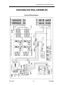
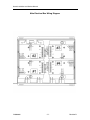
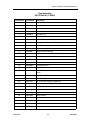
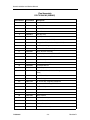
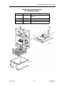
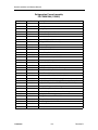
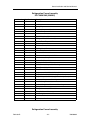
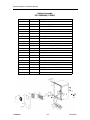
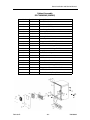
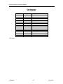
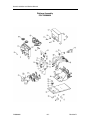
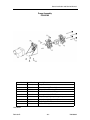
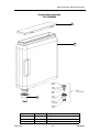
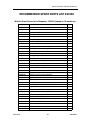
INSTALLATION & SERVICE MANUAL
MODEL QST 4000
IMI CORNELIUS FOODSERVICE GROUP
One Cornelius Place
Anoka, MN 55303
Tel: 1-888-248-5568 / 630-539-5050
Fax: 1-800-344-3801 / 630-539-6960
Part No. 720506904 Rev. B
Revision - April 15, 2002
Table of Contents
UNIT SPECIFICATIONS ...................................................................................... 1
Installation ........................................................................................................... 2
Receiving ........................................................................................ 2
Unpacking ....................................................................................... 2
Counter Location ............................................................................. 2
Filling the Ice Bath .......................................................................... 2
Connecting Water Supply ............................................................... 3
Electrical ......................................................................................... 3
Priming/Flushing Water System ...................................................... 3
Programming the Portion Control ................................................... 3
Cancel/Pour Button ......................................................................... 4
Concentrate Handling & Loading ...................................................................... 5
Loading Concentrate ....................................................................... 5
Changing Concentrate Containers: ................................................. 5
Brixing Procedure .............................................................................................. 6
Supplies .......................................................................................... 6
Checking/Adjusting the Brix Setting ................................................ 6
Planned Maintenance Schedule ........................................................................ 8
Daily ................................................................................................ 8
Weekly ............................................................................................ 8
Semi-Annual ................................................................................... 9
Annually ........................................................................................ 10
Trouble-Shooting Guide .................................................................................. 12
Diagrams and Final Assemblies ...................................................................... 16
Recommended Spare Parts List 115V ............................................................. 41
Recommended Spare Parts List 230V ............................................................. 42
Warranty ............................................................................................................. 43
Quest Installation and Service Manual
UNIT SPECIFICATIONS
Nameplate Data: Model QST 4000, 115 VAC, 4.5 amps, 1 phase 60 hertz, 6.25 oz. (177g) R-134a
refrigerant. Test press: High side 400 psi (27.6 bar). Low side 100 psi (6.9 bar).
Model QST 4000, 230VAC, 3 amps, 1 phase 50 hertz, 6.25 oz. (177g) R-134a
refrigerant. Test press: High side 400 psi (27.6 bar. Low side 100 psi (6.9 bar).
Concentrate Storage: Four 0.8 gallon (3.0 liter) disposable bottles.
Clearance Recommended: 12” (30.48 cm) on top and 4” (10.16 cm) required in back for air circulation.
Electrical Connection: 6 ft. long (1.83 m) power cord with 3-prong plug attached to dispenser. Export
models have line cord less plug.
Power Supply: 15 amps at 120 volts dedicated power supply.
10 amps at 230 volts dedicated power supply.
Water Connection: 3/8 in. (0.95 cm) SAE male flare fitting on dispenser.
Water Supply Requirements: 100 psi (7 bar) maximum static pressure. 20 psi (1.4 bar) minimum
dynamic pressure; i.e., flowing pressure measured at dispenser water inlet with 3.0
ounces (88.7 ml) per second water flow.
Ice Bank/Pull Down: Weight 11-12 lbs. (4.1-4.5 kg.). Pull Down: 3 hours at 75°F (24°C)
Drink Capacity: 143 drinks at (3) 12 oz. drinks per minute not exceeding 45°F (7°C), 75°F ambient/
75°F water (24°C/24°C)
88 drinks at (3) 12 oz. drinks per minute not exceeding 45°F (7°C), 90°F ambient/90°F
water (32°C/32°C)
720506904
-1-
Revision B
Quest Installation and Service Manual
INSTALLATION
RECEIVING
Each unit is completely tested and inspected before shipment. At time of shipment, the carrier
accepts the unit and any claim for damage must be made with the carrier.
Upon receiving from the carrier, please inspect the carton for visible damage. If damage exists,
have the carrier make a note on the bill of lading and file a claim with the carrier.
UNPACKING
•
•
•
•
•
•
Remove staples securing carton to pallet.
Lift carton up and off of unit.
Remove inserts and shipping bag.
Open upper cabinet door and remove installation kit.
Remove bolts securing unit to pallet.
Lift unit off of pallet.
NOTE: Do not lay the unit on sides or on the back. This may cause vital oils to drain
from the compressor resulting in damage during start-up and consequently voiding the warranty.
COUNTER LOCATION
Select a location in a well ventilated area, close to a grounded
electrical outlet. If possible do not place the unit close to hot and/or
steaming machines.
The minimum airflow clearance is: 4” (10.16 cm) in back and 12”
(30.48 cm) on top and open to the front.
IMPORTANT: Condenser air is drawn in from the bottom of the
rear panel and discharged out the top of the rear panel. Failure
to maintain clearance space will reduce capacity of the unit
and cause premature compressor failure.
Typically the dispenser is placed directly on the counter and a food
grade silicone sealant applied around the base. However, 4” legs
that screw into the base of the unit are provided. This eliminates the need to seal the unit to the
counter.
FILLING THE ICE BATH
The ice bath holds approximately 3 gallons (11.4 liter) of
water. The fill tube is located behind the front splash plate
and capped with a 3/8” (0.95 cm) male flare connector. Prior
to attaching the water supply line to the dispenser, use it to
fill the ice bath by attaching it to the connector on the fill tube.
Revision B
-2-
720506904
Quest Installation and Service Manual
Slowly open the water shut off valve and fill the ice bath until water trickles from the overflow. This
is the quickest and easiest way to fill the ice bath.
Once the ice bath is full, store the fill tube in the vertically recessed holder. The fill tube can now be
used as a “sight glass” to monitor the water level in the ice bath.
CONNECTING WATER SUPPLY
The QST series Juice Dispenser is designed to dispense juice at a high flow rate. It is very important that the incoming water line be dedicated for use by the dispenser only and does not have
other machines connected which could cause a water surge, (i.e., a dishwasher, coffee maker,
etc.).
IMPORTANT: The water supply should be consistent with proper water quality
standards (neutral pH of 7.0 to 8.0), and should not be connected to a water softener. It is the installers responsibility to ensure that all water connections to the dispenser are sized, installed, and maintained according to Federal, State, and Local
Laws.
1. Secure the 3/8” (0.95 cm) swivel nut on the flexible supply tubing to the water inlet located at the rear of the dispenser. Make sure that the flared gasket is used (tubing and flared gasket are included with the installation kit).
2. When securing flare nut, use a backup wrench on the male side of the inlet
fitting (unit side) to prevent twisting of the copper tube inside the unit and/or possible damage
to the water strainer/solenoid. A water shut off outside the unit is recommended.
ELECTRICAL
A minimum of 15 amps electrical service is needed for 120VAC power supply.
PRIMING/FLUSHING WATER SYSTEM
To properly prime the unit with water and remove air pockets in
the system, open the cabinet door and make sure that all the
valve levers are in the “Dispense” position.
Close the door and press the dispense button for a
few seconds. Repeat until a steady flow of water is observed flowing from all dispense
valves.
NOTE: Water splashing may occur during this purge cycle.
PROGRAMMING THE PORTION CONTROL
If your dispenser has optional portion controls, they have been pre-programmed from the factory
to pour 7, 12, and 16 ounce drinks. The “extra large” (pitcher icon) size has also been pre-programmed to pour 16 ounces. To change the pour sizes, please follow the instructions below:
1. Simultaneously, press and hold “small” and “extra large” push button switches on the
Portion Control Module until the “Refill” light starts blinking. Release the switches.
The blinking Refill light indicates the programming mode is active.
2. Place the cup under the dispense nozzle and push the selected size button (small,
medium, large, or extra large). Hold the button in until the cup fills to the desired portion, then release the button. Repeat the above procedure for the remaining sizes.
720506904
-3-
Revision B
Quest Installation and Service Manual
3. After programming all the drink sizes, press and release the “cancel/pour” switch
to return the Portion Control to the operational mode. The blinking REFILL light will
go out.
If at a future date it is decided to change the portion size of the drinks, the individual sizes can be
adjusted by the above procedure. It is not necessary to reprogram every size. Additionally the portion control has full memory retention in case of a power failure.
CANCEL/POUR BUTTON
To pour a drink without using a pre-programmed portion control size, simply push and
hold the Cancel/Pour button. Release when the glass is full.
Revision B
-4-
720506904
Quest Installation and Service Manual
CONCENTRATE
HANDLING & LOADING
It is recommended that the concentrate be thawed in a refrigerated 35°F-40°F (1.6°C-4.4°C) compartment for a minimum of 48 hours prior to loading into the Quest Juice Dispenser.
WARNING: Concentrate must be completely thawed and within the temperature
range of 35°F-40°F (1.6°C-4.4°C) prior to loading. Failing to supply concentrate inside the recommended temperature range, especially below 35°F (1.6°C), will cause
an out of brix drink (refer to the Brixing Procedure section for details).
LOADING CONCENTRATE
The Quest Juice Dispenser is designed to use either disposable juice concentrate containers or the optional Cornelius generic refillable container sold separately.
1. Thoroughly shake concentrate prior to use.
2. Place concentrate containers on the dispensing platform shelf inside the
refrigerated cabinet.
3. Engage the concentrate container by pressing it downward into the bottle adapter opening on
the dispensing platform.
NOTE: Be sure to lubricate the o-ring seal on the container nozzle. This will ensure
a good seal and allow the pumps to draw concentrated from the containers more
easily. Failure to create a good seal at this connection may result in weak drinks
and/or seepage of concentrate.
4. Prime each pump by closing the cabinet door and press each dispense button until concentrate flows from the dispense nozzles.
CHANGING CONCENTRATE CONTAINERS:
1. Open the cabinet door and move the valve handle from “Dispense” to “Flush”
2. Close the door. Depress and hold the dispense button until clear water flows from the dispense nozzle.
3. Open the cabinet door and return the handle to “Dispense”.
4. Depress and hold the dispense button for 1-2 seconds. This will relieve water pressure from
the concentrate pump system.
5. Load concentrate container (see Loading Concentrate).
720506904
-5-
Revision B
Quest Installation and Service Manual
BRIXING PROCEDURE
NOTE: If concentrate is not properly thawed, it will adversely affect the amount of
concentrate dispensed. Thawed product should be between 35°F/1.6°C to 40°F/
4.4°C.
SUPPLIES
•
•
•
•
•
•
1-Small 12 oz. cup (354.8 ml)
1-Large 21 oz. cup (621.1 ml)
1-Straw
Paper Toweling
1-Thermometer
1-Refractometer
Your will also need a flat blade screwdriver to turn a screw if brix adjustments are required.
NOTE: The refractometer shown above, P/N 511004000, is available through your
local Cornelius Distributor.
CHECKING/ADJUSTING THE BRIX SETTING
The following instructions are for use with a refractometer.
1. Dispense approximately 8 oz. (236 ml) of drink and discard. Now draw a second 8 oz. drink.
2. Check drink temperature with a reliable thermometer (target is 35-45°F, or 1.6-7.2°C). Discard
this drink after checking temperature.
NOTE: If drink temperature is not within the target range, refer to the basic troubleshooting section.
3. Dispense a 12 oz (354.8 ml) drink sample into a clean, dry cup. Thoroughly stir the sample
using a straw.
4. Using a straw, transfer a small sample of finished drink to the refractometer lens (refer to operating instructions supplied with your refractometer). Check the brix reading against the brix
chart below.
Note: The following brix chart is generic and intended for reference use only. Contact your frozen concentrate supplier for specific brix readings.
Brix Reference Chart
Flavor
Ratio
Orange Juice
4+1
Grapefruit Juice
5+1
Cranberry Cocktail
4+1
Apple Juice
5+1
Grape
5+1
Lemonade
5+1
Tropical Punch
5+1
Sweetened Iced Tea
7+1
Pineapple Juice
4+1
Prune Juice
2+1
Revision B
-6-
Brix
11.8
10.6
13.5
12.0
13.0
10.5
11.8
6.0
12.8
16.0
720506904
Quest Installation and Service Manual
5. To change the brix setting, simply readjust the water flow rate. Located on each of the valve assemblies inside the refrigerated compartment are the adjusting screws for the water flow rate (one per valve).
If the brix reading is too high or low, rotate the appropriate water flow
control according to the diagram below. Repeat steps 1-5 until the brix
setting is achieved.
Lowers Brix by increasing water
Raises Brix by reducing water
IMPORTANT: When making changes to the water flow control, do not rotate more
than 1/4 turn per adjustment. Additionally, prior to taking your next brix reading,
“tap” the corresponding dispense button several times prior to drawing a sample.
This will clear remnant drink from the dispense nozzle AND help move the flow control to its new setting.
720506904
-7-
Revision B
Quest Installation and Service Manual
PLANNED
MAINTENANCE
SCHEDULE
DAILY
Flush System:
1. Move Dispense/Flush levers located on the platform assembly in the
refrigerated cabinet to the “Flush” position. Place an empty cup on the
drip tray below each dispense nozzle.
2. Close the door and depress each dispense button for 2-3 seconds or
until clear water flows from each dispense nozzle.
3. Return the Dispense/Flush levers to the “Dispense” position.
4. Press each dispense button for 1-2 seconds to release the water pressure present in the concentrate pump system.
Clean Splash Zones & Dispense Nozzles:
1. On a daily basis, clean the external cabinet and splash areas
using a clean damp cloth. Remove and wash the cup rest and
drip tray using a mild dish soap.
2. Remove the dispense nozzles and static mixers by rotating
each 90° and pulling down. Remove the mixing chambers by
pulling straight forward. Wash using a mild dish soap.
IMPORTANT: DO NOT wash nozzles, static mixers, or
mixing chambers in a dish washer. This will distort the
plastic and damage the o-rings. Additionally, do not
soak them in sanitizing solution longer than 2 minutes.
WEEKLY
Check concentrate to water brix ratio (refer to the Brixing Procedure in this manual).
Sanitize the Juice Dispenser:
STEP 1 - RINSE WITH HOT WATER
R
1. Prepare two 2 oz. packets of Stera-Sheen Green Label sanitizing solution (or similar brand)
by dissolving each packet in 1 gallon (3.8L) of potable water to insure 200 ppm of available
chlorine.
IMPORTANT: Use potable water at 80°F-100°F (26.7°C-37.8°C). Water above this
range will breakdown the chlorine count and minimize sanitation.
2. Remove the juice concentrate containers and place them in separate refrigerated compartment.
3. “Flush” the system by following the instructions in the Daily Section.
Revision B
-8-
720506904
Quest Installation and Service Manual
4. Fill a clean empty concentrate container with one quart of extremely hot tap water, approximately 140°F (60°C) and place into unit. Dispense all of the hot water into a large container.
Repeat for the remaining dispense valves.
5. Remove the mixing chambers, nozzles, and static mixers. Rinse in hot water to remove excess pulp and concentrate.
6. Place the mixing chambers, nozzles, and static mixers in a separate container of sanitizing
solution and agitate vigorously. Allow the parts to soak for two minutes. Rinse thoroughly with
fresh tap water.
7. Reinstall the static mixer, nozzles, and mixing chambers.
STEP 2 - SANITIZE PUMP SYSTEM
8. Fill a clean concentrate container with 2 quarts (1.9L) of fresh sanitizing solution.
9. Place handles in the “dispense” position and close the door.
10. Press and hold the dispense button for 90 seconds then stop. Allow sanitizing solution to remain in the lines for 5 minutes.
11. After 5 minutes, dispense the remaining sanitizing solution.
STEP 3 - PREPARE DISPENSER FOR USE
12. Replace sanitizing solution container with a concentrate container and close the door.
13. Press and hold the dispense button until juice appears from the nozzle. Next dispense and
discard at least two 8 oz. (236.6ML) cups of juice in order to prime the system and prepare it
for operation.
SEMI-ANNUAL
CAUTION: The following procedures require removal of the dispenser side panel(s). Disconnect the power cord from the receptacle prior
to proceeding.
Clean Water Inlet Strainer:
1. Remove the right side panel from the dispenser.
2. Turn off the water supply to the dispenser.
3. Remove the access port from the “Y” shaped water inlet solenoid located on the right side of the dispenser.
4. Clean and reinstall the stainless steel water strainer.
Clean Chassis Interior:
1. Clean the condenser cooling fins.
2. Clean the air inlet grilles located on the rear and top panels of the dispenser.
3. Clean the interior base.
4. Wipe the fan blade clean.
5. Reinstall the right side panel, turn on the water supply, and plug the dispenser into the power
receptacle.
720506904
-9-
Revision B
Quest Installation and Service Manual
Check and Top-Off Water Ice Bath:
1. Remove the drip tray and lower splash panel.
2. If the Ice bath level is below the “Full” indicator, top it off with water. Refer to the Filling the Ice
Bath procedure in the Installation section of this manual.
ANNUALLY
Replace Pump Tubing:
A replacement pump tubing kit,
part#45098, is available. The kit consists of one pre-cut length of pump
tubing, two white plastic hose clamps,
and instructions.
Water Inlet
Quick Connector
Concentrate Delivery
Tubes
Bottle Adapter
(Juice Inlet)
Hose Clamp
Dispense/Flush
Lever
Thumb
Screws
Removing Pump Platform(s):
1. Remove the concentrate containers from the dispenser and place
them in a refrigerator.
2. Remove the cabinet shelf that the
concentrate containers sit on.
Brix
Adjustment
Screws
Locking
Latch
Mixing
Chamber
3. Flush the system prior to removing the pump platform (refer to the
Daily section located at the beginning of the Planned Maintenance
Schedule). Remove the dispense
nozzles and static mixers.
Fig.1
Water
Manifold
4. Unplug the water line quick disconnect by pressing the gray button (see Fig. 1&2).
5. Slide the locking latch forward. Lift
the platform slightly and pull forward to gain access to the electrical connector (see Fig.1).
Pump
Motor
6. Unplug the electrical connector by
squeezing the locking tabs on either side and pulling out the connector. Lift and remove the pump
platform (see Fig.1).
Front & Rear
Pump Halves
Water
Solenoid
Fig.2
Replacing Pump Tubing:
1. Remove pump platform (refer to the Removing Pump Platform(s) procedure located earlier in this section).
2. Remove the two white plastic hose clamps from the pump tube connections (see Fig. 1&2). Remove the concentrate delivery tubes from
the hose ends.
3. Loosen and remove the four thumb screws from the pump body.
4. Remove the rear pump body half only to reveal the pump tube and rollers.
Revision B
- 10 -
720506904
Quest Installation and Service Manual
5. Remove the old pump tube from the pump body. If the roller assembly comes out with the tubing, place it back into the pump housing being sure to align the roller assembly shaft keyway
to the motor shaft so that the two interlock.
6. Firmly press the new hose into the pump body around the
roller assembly, being sure to keep the protruding ends
even with each other.
7. Once the tubing is in place, hold the tubing with one hand,
capture the lower part of the tubing with the outer housing,
then proceed to capture the shaft of the roller assembly and
push the rear pump housing into place. Make sure to capture the tubing within the body and not pinch it between the
halves. Do not use any tool other than your finger tips to manipulate the tubing into the housing or you may damage the tube.
8. While holding the pump halves together with your hand, reinsert the four thumb screws and tighten using a criss-cross
pattern as shown. The thumb screws should be tightened
about 1/4 turn beyond snug.
9. Insert the two concentrate delivery tubes into the pump tubing ends and secure them using the new hose clamps supplied in the kit. Be sure to use pliers to squeeze and tighten
the hose clamps.
720506904
- 11 -
Revision B
Quest Installation and Service Manual
TROUBLE-SHOOTING
GUIDE
The following pages contain trouble-shooting information intended to aid an experienced service
person in diagnosing operational problems that may occur. For further assistance, contact the IMI
Cornelius Technical Services department at 1-888-248-5568 (630-539-6850 outside the United
States) between the hours of 7:30A.M. and 5:00P.M. Central Standard Time. You must have the
model and serial number (Located on the right side of the dispenser) prior to calling.
PROBLEM
PROBABLE CAUSE
Totally Inoperative •
No cooling
No power to dispenser due to
tripped circuit breaker
•
Reset circuit breaker. Confirm
that breaker is correct size and
no other equipment is operating
on the same circuit. Also confirm
that supply voltage is +/- 10% of
nameplate specifications.
•
Loose or broken power supply
connection inside dispenser.
•
Repair connection.
•
Line voltage is not within +/- 10% •
of nameplate specifications causing compressor overload to trip
Contact an electrician
•
No water in water ice bath or
•
water level extremely low exposing the ice bank sensing probe
Fill ice bath to proper water level
•
Defective Ice Bank Control or
sensing probe
•
Replace
•
Cabinet fan is inoperative resulting in warm concentrate (water
continues to cool)
•
Replace
•
Compressor short cycles on
overload
•
Excessively high discharge pressure due to restricted condenser
or inoperative condenser fan
motor
•
Compressor starts but hums and •
trips overload
Seized or shorted compressor,
replace
•
Defective compressor overload
or start capacitor
•
Test and replace
•
Compressor starts but does not
switch off of start winding
•
Relay or compressor is defective.
Test and replace faulty item
•
Refrigerant leak
•
Repair leak, evacuate and
recharge system
No water to dispenser
•
Restore Water
Water supply line inside refrigerated cabinet disconnected from
pump platform
•
Reconnect
No water dis•
pensed, concentrate only
•
Revision B
REMEDY
- 12 -
720506904
Quest Installation and Service Manual
PROBLEM
PROBABLE CAUSE
No water dis•
pensed, concentrate only
(continued)
•
Disassemble and clean solenoid. Replace if necessary.
•
Main water solenoid/strainer
•
located at the rear of dispenser is
clogged, binding or defective
Remove and clean strainer. Confirm 28VDC is present at solenoid
during dispense. Confirm solenoid coil is not open. Disassemble and clean solenoid.
•
Water supply pressure is greater •
than 100 psi (7 bar) forcing the
brix flow control closed
Add external regulator and lower
pressure to 40 psi (3 bar)
•
Freeze-up of water coil in ice
bath
•
Unplug dispenser and allow 2-4
hours to thaw. Check operation of
agitator motor and ice bank control.
•
Refrigeration system may be low
on charge resulting in a deformed
ice bank and freeze-up of the
water coil in the ice bath.
Black service switch located on
the rear of the cabinet door in
OFF position
•
Turn on switch
•
White door switch open
•
Door switch must be closed in
order to dispense. Check switch
operation and replace if necessary.
•
6.25 amp fuse inside front electri- •
cal box blown
Replace with 6.25, 250VAC slow
blow fuse and test
•
No output from Transformer
•
Confirm transformer output by of
26VAC +/- 2. Replace transformer if necessary.
•
Defective voltage regulator board •
(VRB) located inside front electrical box
Measure across the VDC output
of the board. There should be
28VDC present when the dispense button is pressed.
Replaced VRB if necessary.
•
Defective dispense push button
or portion control board
•
Test and replace if necessary
Concentrate container not fully
•
engaged into receptacle on pump
platform
Refer to Concentrate Loading
section of this manual
•
Dispense/Flush lever in FLUSH
position
•
Move lever to DISPENSE position
•
Concentrate too cold, not properly thawed
•
Concentrate should be 35-40°F
(1.7-4.5°C) prior to loading
•
Defective pump motor
•
Replace pump motor
No water and no •
concentrate, refrigeration is working
No concentrate •
dispensed, water
only
720506904
Water solenoid located on pump
platform clogged or defective
REMEDY
- 13 -
Revision B
Quest Installation and Service Manual
PROBLEM
Warm Drink
PROBABLE CAUSE
REMEDY
•
Ambient air around dispenser is
too warm
•
Excessive demand on dispenser •
Add water pre-cooler or second
dispenser
•
Dirty condenser coil
•
Clean condenser coil
•
Inoperative condenser fan
•
Replace condenser fan motor
•
Defective Ice Bank Control
•
Test and replace if necessary
•
Loss of refrigerant charge due to •
leak in system
Repair leak and recharge system
Water continuous- •
ly drips from nozzle when in OFF
mode
Main water solenoid at base of
unit or water solenoid on pump
platform not shutting off tightly
•
Clean solenoid(s), replace parts
as necessary (refer to the
Planned Maintenance Section)
Concentrate
•
warm, water cold
Cabinet fan inoperable
•
Check/replace fan
•
Agitator motor/pump inoperable
or restricted
•
Check/replace agitator motor
•
Loss of refrigerant charge due to •
leak in system
Repair leak and recharge system
•
Water supply pressure too low,
•
less than 20 psi (1.4 bar) flowing
water pressure fluctuates sharply
Correct water supply problem to
ensure a constant 40 psi (3 bar)
flowing to the dispenser
•
Water flow control binding or
spring is defective
Clean and/or replace parts as
necessary
•
Improperly thawed concentrate. •
Brix changes as the concentrate
temperature changes (concentrate becomes thinner as temperature rises)
Concentrate should be 35-40°F
(1.7-4.5°C) prior to loading
Pump motor defective
•
28VDC should be present at
pump motor during dispense. If
voltage is present and motor
does not start, replace pump
motor
•
No power to transformer or no
28VAC output from transformer
•
Confirm transformer has line voltage present on primary side. If no
28VAC output from the secondary replace transformer
•
Defective voltage regulator board •
(VRB) located inside front electrical box
Confirm board produces 28VDC
present when the dispense button is pressed (refer to the Electrical Box Wiring Diagram for
VDC output location). Replace
VRB if necessary
•
Defective dispense control board •
(Push button or portion control)
Test and replace if necessary
Brix Problem
Pump Inoperative •
Revision B
- 14 -
•
•
Relocate dispenser
720506904
Quest Installation and Service Manual
PROBLEM
PROBABLE CAUSE
Machine contin- •
ues to dispense
after dispense button is released or
dispenses without
operator input
•
720506904
Push button or portion control
pad stuck in on position
REMEDY
•
Disconnect the wire harness from
the rear of the portion control and
close the door. If unit does not
dispense on its own the dispense
control board is bad (stuck on)
Relay on voltage regulator board •
(VRB) stuck on.
Disconnect the 4-wire harness
from the lower right corner of the
VRB. If the unit continues to dispense on its own the VRB is
defective (relay stuck on)
- 15 -
Revision B
Quest Installation and Service Manual
DIAGRAMS AND FINAL ASSEMBLIES
System Wiring Diagram
Revision B
- 16 -
720506904
Quest Installation and Service Manual
Main Electrical Box Wiring Diagram
720506904
- 17 -
Revision B
Quest Installation and Service Manual
Final Assembly
P/N 721544101 (115VAC)
Item Number Part Number
Description
1
720500204
Rear Panel
2
720500301
Right Side Panel
3
720500302
Left Side Panel
4
720500504
Splash Panel
5
720500014
Grill, Drip Tray
6
720500104
Drip Tray
7
720505204
Cabinet Assembly (115VAC)
8
720500804
Refrigeration Chassis Assembly (115VAC)
9
720702702
Pin, Threaded Hinge
10
720401301
Merchandiser, Generic Graphics
11
720703402
Hinge, Bracket Assembly
12
720500763
Washer, Nylon, 0.437 OD X 0.195 ID
13
720508704
Lower Door Assembly, Push Button
14
720500704
Door Assembly
15
720506804
Kit, Literature Package
16
720506904
Installation Manual
17
720507004
Flavor Strip
18
720507101
Nozzle Static Mixer (Includes O-ring, nozzle, & static
mixer)
*
720507103
Static Mixer Only
*
31525037
Nozzle O-ring
23*
720511299
Kit, Flavor Strip, Magnetic Receptacle
24
0704105
Screw, #8-32 X 1/2” Lg., THMS
25*
720511201
Kit, Flavor Strip
26*
720507201
NPLT
27
720500404
Top Panel
28
720507304
Shelf, Cabinet
29
720506402
Platform Assembly
32
720500713
Switch, Cutout, 10 A
33
720500726
Bracket, Reset Switch
34
720504904
Base Frame Assembly
Revision B
- 18 -
720506904
Quest Installation and Service Manual
Final Assembly
P/N 721544102 (230VAC)
Item Number Part Number
Description
1
720500204
Rear Panel
2
720500301
Right Side Panel
3
720500302
Left Side Panel
4
720500504
Splash Panel
5
720500014
Grill, Drip Tray
6
720500104
Drip Tray
7
720505205
Cabinet Assembly (230VAC)
8
720500805
Refrigeration Chassis Assembly (230VAC)
9
720702702
Pin, Threaded Hinge
10
720401301
Merchandiser, Generic Graphics
11
720703402
Hinge, Bracket Assembly
12
720500763
Washer, Nylon, 0.437 OD X 0.195 ID
13
720508704
Lower Door Assembly, Pushbutton
14
720500704
Door Assembly
15
720506804
Kit, Literature Package
16
720506904
Installation Manual
17
720507004
Flavor Strip
18
720507101
Nozzle Static Mixer (Includes O-ring, nozzle, & static
mixer)
*
720507103
Static Mixer Only
*
31525037
Nozzle O-ring
23*
720511299
Kit, Flavor Strip, Magnetic Receptacle
24
0704105
Screw, #8-32 X 1/2” Lg., THMS
25*
720511201
Kit, Flavor Strip
26*
720507201
NPLT
27
720500404
Top Panel
28
720507304
Shelf, Cabinet
29
720506402
Platform Assembly
32
720500713
Switch, Cutout, 10 A
33
720500726
Bracket, Reset Switch
34
720504904
Base Frame Assembly
720506904
- 19 -
Revision B
Quest Installation and Service Manual
Final Assembly
P/N 721544101 (115VAC)
P/N 721544102 (230VAC)
Revision B
- 20 -
720506904
Quest Installation and Service Manual
Refrigeration Chassis Assembly
P/N 720500804 (115VAC)
Item Number Part Number
720506904
Description
1
720501304
Frame Assembly, Refrigeration
(115VAC)
2
720500904
Foamed Water Bath Tank Assembly
3
720504004
Tank Cover Assembly (115VAC)
4
0702609
Screw, #8-32 BHMS, 3/4” Lg.
- 21 -
Revision B
Quest Installation and Service Manual
Refrigeration Chassis Assembly
P/N 720500805 (230VAC)
Item Number Part Number
Revision B
Description
1
720501305
Frame Assembly, Refrigeration
(230VAC)
2
720500904
Foamed Water Bath Tank Assembly
3
720504005
Tank Cover Assembly (230VAC)
4
0702609
Screw, #8-32 BHMS, 3/4” Lg.
- 22 -
720506904
Quest Installation and Service Manual
Refrigeration Frame Assembly
P/N 720501304 (115VAC)
Item Number Part Number
Description
1
N/A
2
N/A
3
08474
Spring Clip
4
9649
Washer, Compressor Mount
5
12107
Sleeve, Compressor Mount
6
N/A
7
45073
Dryer-Solid Core, R-134a
8
48456
Tubing, 1/4” X 3/8” Premier Python
10
400276
Rivet
11
3110001
Fastener-Rivnut, #8-32
12
7221320
Bushing-Strain Relief
13
45091001
Valve, Water Solenoid, 24V
14
440000904
Probe, Ice Bank
15
560003705
Condenser Assembly, 115V/60Hz
16*
720500799
Wire Harness, Compressor
17
720501404
Product Coil Assembly
18
720501704
Evaporator Coil Assembly
19
720501805
Tube, Formed, Compressor Discharge
20
720501806
Tube, Formed, Liquid Line
21
720502004
Tube, Formed, Process Line
22
720503201
Compressor, 1/10 HP. 120V/60Hz, R-134a
*
720503206
Comp. Overload, 120V/60Hz (supplied w/compressor)
*
720503207
Comp. Relay, 120V/60Hz (supplied w/compressor)
*
720503208
Comp. Start Capacitor, 120V/60Hz (supplied w/compressor)
23
720503203
Grommet, Compressor Mounting
24
720503604
Heat Exchange Assembly
26
720201415
Bracket, Compressor/Condenser Mounting
27
720508404
Refrigeration Frame
28*
720509203
Fitting, Connector, 3/8TB X 3/8”
29
720509701
Fitting, Bulkhead Water
30
720500012
Washer, Split-Lock 0.641”I.D.
31
720509702
Jam Nut, Bulkhead
32
750300015
Bracket, Ice Bank Probe
720506904
- 23 -
Revision B
Quest Installation and Service Manual
Refrigeration Frame Assembly
P/N 720501305 (230VAC)
Item Number Part Number
Description
1
N/A
2
N/A
3
08474
Spring Clip
4
9649
Washer, Compressor Mount
5
12107
Sleeve, Compressor Mount
6
N/A
7
45073
Dryer-Solid Core, R-134a
8
48456
Tubing, 1/4” X 3/8” Premier Python
9
89099
Gasket, Foam-Tape 31.27”
10
400276
Rivet
11
3110001
Fastener-Rivnut, #8-32
12
7221320
Bushing-Strain Relief
13
45091001
Valve, Water Solenoid, 24V
14
440000904
Probe, Ice Bank
15
560003706
Condenser Assembly, 230V/50Hz
16*
720500799
Wire Harness, Compressor
17
720501404
Product Coil Assembly
18
720501704
Evaporator Coil Assembly
19
720501805
Tube, Formed, Compressor Discharge
20
720501806
Tube, Formed, Liquid Line
21
720502004
Tube, Formed, Process Line
22
720503202
Compressor, 1/10 HP. 230V/50Hz, R-134a
*
720503209
Comp. Overload, 230V/50Hz (supplied w/compressor)
*
720503210
Comp. Relay, 230V/50Hz (supplied w/compressor)
23
720503203
Grommet, Compressor Mounting
24
720503604
Heat Exchange Assembly
26
720201415
Bracket, Compressor/Condenser Mounting
27
720508404
Refrigeration Frame
28*
720509203
Fitting, Connector, 3/8TB X 3/8”
29
720509701
Fitting, Bulkhead Water
30
720500012
Washer, Split-Lock 0.641”I.D.
31
720509702
Jam Nut, Bulkhead
32
750300015
Bracket, Ice Bank Probe
Refrigeration Frame Assembly
Revision B
- 24 -
720506904
Quest Installation and Service Manual
P/N 720501304 (115VAC)
P/N 72051305 (230VAC)
720506904
- 25 -
Revision B
Quest Installation and Service Manual
Tank Cover Assembly
P/N 720504004 (115VAC)
Item Number
Part Number Description
1
720522001
Rear Support, Electrical Box
2
720509904
Bracket, Transformer
3
720521101
Bracket, Ice Bank Control
4
720509225
Split Grommet
5
720509224
Grommet
6
720509222
Grommet
7
720508104
Tank Deck Insulation
8
720504304
Electrical Box Assembly
9
720503404
Deck, Refrigeration
10
720502800
Agitator Assembly (115VAC)
12
720500795
Transformer (115VAC)
13
440000902
Ice Bank Control, 120VAC
14
07061001
Screw, #10 Type “F” HHWF, 3/8” Lg.
15
0704105
Screw, #8-32 X 1/2” Lg., THMS
16
48456
Tubing, 1/4” X 3/8”
17*
720500799
Wire Harness, Compressor
18
400276
Rivet
19
720509207
Elbow Fitting, 3/8” X 5/16” JG
23*
440000907
P- Housing, Electrical Plug A GIBC
24*
440000908
P- Housing, Electrical Plug B GIBC
25*
440000909
P- Housing, Electrical Plug C GIBC
26*
440000919
P- Cover “A”
27*
440000920
P- Cover “B”
28*
440000921
P- Cover “C”
29
0704101
Screw, #8-32 X 3/8” Lg., THMS
30
3110001
Nut, Rivet
31
0734801
Pop Rivet
32
720503001
Outlet Tube, 3/8 ID
33
720503101
Inlet Tube, 3/8 ID
34
48114008
Clamp, Oetiker 19.8
*Not Shown
Revision B
- 26 -
720506904
Quest Installation and Service Manual
Tank Cover Assembly
P/N 720504005 (230VAC)
Item Number
Part Number Description
1
720522001
Rear Support, Electrical Box
2
720509904
Bracket, Transformer
3
720521101
Bracket, Ice Bank Control
4
720509225
Split Grommet
5
720509224
Grommet
6
720509222
Grommet
7
720508104
Tank Deck Insulation
8
720504304
Electrical Box Assembly
9
720503404
Deck, Refrigeration
10
720502803
Agitator Assembly (230VAC)
12
720500794
Transformer (230VAC)
13
440000901
Ice Bank Control, 230VAC
14
07061001
Screw, #10 Type “F” HHWF, 3/8” Lg.
15
0704105
Screw, #8-32 X 1/2” Lg., THMS
16
48456
Tubing, 1/4” X 3/8”
17*
720500799
Wire Harness, Compressor
18
400276
Rivet
19
560002319
Elbow Fitting, 3/8” X 5/16” JG
23*
440000907
P- Housing, Electrical Plug A GIBC
24*
440000908
P- Housing, Electrical Plug B GIBC
25*
440000909
P- Housing, Electrical Plug C GIBC
26*
440000919
P- Cover “A”
27*
440000920
P- Cover “B”
28*
440000921
P- Cover “C”
29
0704101
Screw, #8-32 X 3/8” Lg., THMS
30
3110001
Nut, Rivet
31
0734801
Pop Rivet
32
720503001
Outlet Tube, 3/8 ID
33
720503101
Inlet Tube, 3/8 ID
34
48114008
Clamp, Oetiker 19.8
*Not Shown
720506904
- 27 -
Revision B
Quest Installation and Service Manual
Tank Cover Assembly
P/N 720504004 (115VAC)
P/N 720504005 (230VAC)
Revision B
- 28 -
720506904
Quest Installation and Service Manual
Cabinet Assembly
P/N 720505204 (115VAC)
Item Number
720506904
Part Number Description
1
45051
Stud-Latch #10-32
2
720505404
Liner Assembly, Quest 4000
3
720506104
Fan Motor (115VAC)
4
720506304
Rear Cabinet Panel, Quest 4000
5
3110001
Fastener, Rivnut, #8-32
6
720506204
Water Coil, Quest 4000
7
720519801
Bracket, Cabinet Harness
8
723232
Insert, Expansion, #10-32
9
720200206
Fitting, Insert 3/8” NPTM Quest 4000
10
720506106
Fan Guard
11
0704101
Screw, #8-32 X 3/8” Lg., THMS
12
0705806
Screw, #10-32 X 5/8” Lg., FHMS
13
04441
Lower Space
14
720702702
Pin, Threaded Hinge
15
720703402
Hinge Bracket Assembly
16
720500787
Door Catch
17
720511401
Lower Cabinet Panel, Quest 4000
19
720511301
Nozzle Plate
20
0704105
Screw, #8-32 X 1/2” Lg., THMS
21
720509206
Fitting, Union Elbow, 3/8” X 1/2” JG
22
8468
#10 S.S. Star Washer
23
720500711
Harness Assembly, Pump Platforms, Quest 4000
- 29 -
Revision B
Quest Installation and Service Manual
Cabinet Assembly
P/N 720505205 (230VAC)
Item Number
Revision B
Part Number Description
1
45051
Stud-Latch #10-32
2
720505404
Liner Assembly, Quest 4000
3
720506105
Fan Motor (230VAC)
4
720506304
Rear Cabinet Panel, Quest 4000
5
3110001
Fastener, Rivnut, #8-32
6
720506204
Water Coil, Quest 4000
7
720519801
Bracket, Cabinet Harness
8
723232
Insert, Expansion, #10-32
9
720200206
Fitting, Insert 3/8” NPTM Quest 4000
10
720506106
Fan Guard
11
0704101
Screw, #8-32 X 3/8” Lg., THMS
12
0705806
Screw, #10-32 X 5/8” Lg., FHMS
13
04441
Lower Space
14
720702702
Pin, Threaded Hinge
15
720703402
Hinge Bracket Assembly
16
720500787
Door Catch
17
720511401
Lower Cabinet Panel, Quest 4000
19
720511301
Nozzle Plate
20
0704105
Screw, #8-32 X 1/2” Lg., THMS
21
720509206
Fitting, Union Elbow, 3/8” X 1/2” JG
22
8468
#10 S.S. Star Washer
23
720500711
Harness Assembly, Pump Platforms, Quest 4000
- 30 -
720506904
Quest Installation and Service Manual
Door Assembly
P/N 720500704
Item Number
Part Number
Description
1
720500725
Rear Door Assembly
2
720500707
Light Panel Assembly
*
31314
Fluorescent Bulb
*
45433
Lamp Holder
*
720511606
Ballast Board
3
720500710
Molded Gasket
4
720500780
Latch Button Assembly
*
Key
5
45432
Rocker Switch, Sealed
6
720500765
Bottom Hinge Plate
7
720500764
Top Hinge Plate
8
400276
Rivet
9
0704101
Screw, #8-32 X 3/8” Lg., THMS
*Not Shown
720506904
- 31 -
Revision B
Quest Installation and Service Manual
Door Assembly
P/N 720500704 (Rev. B)
Revision B
- 32 -
720506904
Quest Installation and Service Manual
Lower Door Panel Assembly - Push Button
P/N 720508704
Item Number Part Number Description
1
720508502
Bezel, Push Button
2*
720508601
Overlay “Push”
3
07301029
Nylon Flat Washer, 0.312” OD X 0.125 ID
4
0712901
Screw, #4 Type “B” BH
5
720508801
Board, Push Button
6
720508904
Lower Door Panel
7
720511299
Magnetic Flavor Strip Receptacle
*Not Shown
Lower Door Panel Assembly - Portion Control
P/N 720508705
Item Number Part Number Description
720506904
1
720508904
Lower Door Panel
2
720508802
Board, Portion Control
3
720508602
Overlay, Portion Control
4
720508505
Bezel, Portion Control
5
07301029
Nylon Flat Washer, 0.312” OD X 0.125 ID
6
0712901
Screw, #4 Type “B” BH
7
720511299
Magnetic Flavor Strip Receptacle
- 33 -
Revision B
Quest Installation and Service Manual
Platform Assembly
P/N 720500039
Item Number
Part Number Description
1
77052102
Fitting, Elbow, 90 deg, 1/4” Barb
2
720506702
Bracket, Valve Mount, Quest
3
771000306
Fitting, 3.8”, 90 deg. Barb, 1.3” long
4
720509111
Tube, 2.25” Straight Plastic
5
720509114
Tube, 3.5” Long, Radius
6
48114004
Clamp-Ear, 105 (.413/.346)
7
48114002
Clamp-Ear, 170 (.669/.571)
8
720509304
Manifold, Water S.S.
9
724558601
Clip, Retainer Tube
10
720500033
Mixing Chamber
11
720500041
Standoff-Cover
12
45529
Nut, #8-32
13
720506604
Base, Platform
14
720507404
Front Cover, Platform
15
720501209
Hook Washer, Hold Down
16
720509103
Tube Assembly, Suction
17
720720498
Coupling, In-Line, 3/8” I.D., HFC35
18
31525003
O-Ring, 3/8” O.D. X .239” I.D.
19*
11732
Wire Harness, Platform, SLJ1000-2
20
45026
Bottle Adapter Assembly
21
45046
Latch-#2 Medium, S.S.
22
45047
Guide-latch, #2 Medium
23
45048
Washer-latch, #2 Medium
24
45049
Rivet-latch, 3/8” Dia. HD., S.S.
25
0704105
Screw, #8-32 X 1/2” Lg., THMS
26
07032001
Screw, #8-18 X 7/16” Type “25”, HHWF S.S.
27
45508200
Valve Block Assembly
28
720201500
Grommet, Platform Cover
29
45185
Pump & Motor Assembly, 3-Roller
30
48195006
Clamp, Hose .470 I.D.
31
49034
Tube, Tygon, 3/8” X 5/8” O.D.
32
7245072
Label, Dispense/Flush
33
720201707
Bracket, Water Adjust Cover
*Not Shown
Revision B
- 34 -
720506904
Quest Installation and Service Manual
Platform Assembly
P/N 720500039
720506904
- 35 -
Revision B
Quest Installation and Service Manual
Pump Assembly
P/N 45185
Item Number
Part Number
Description
1
45016001
Pump Gear Motor
2
45728001
Rotor Assembly (Thick Wall)
3
45050
Pump & Motor Mounting Block
4
45017001
Thumb Screw, #8-32 X 3” Lg.
5
0702905
Screw, #8-32 X 3/4” FHMS
6
45098
Pump Tubing Kit (pump tubing, clamps, & instructions
*
45078
Pump Assembly (Items 2 & 7)
7
45727
Pump Body, Front/Rear
8
45283
Rubber Bushing w/Nut Insert
*Not Shown
Revision B
- 36 -
720506904
Quest Installation and Service Manual
Bottle Adapter Assembly
P/N 45026
Item Number
720506904
Part Number Description
1
45060001
Caddy Adapter, Top
2
45060002
Run & Flush Valve
3
45060003
Caddy Adapter, Bottom
4
31525062
O-Ring 0.276 OD X 0.118 ID
5
31525064
O-Ring 5/8” OD X 0.489 ID TFE/SIL
6
31525061
O-Ring 1.489” ID X 0.070” Dia.
*
45026100
O-Ring Kit (includes all O-rings
needed to rebuild bottle adapter)
7
07015001
Screw, #8-18 Hi-Lo, Ph.
8
45043
Pin-Sensor, Sold Out
10
6006821
Switch, Snap Action
11
45076
Actuator Pin
12
60067086
Screw, #2-56 X 7/16” PH, SS
13
45084001
Caddy Plate
14
31525014
O-Ring 5/8” OD X 0.489 ID
15
7222081
Hold Down Washer
16
07032001
Screw, #8-18 X 7/16 Type “25” HHWF
- 37 -
Revision B
Quest Installation and Service Manual
Valve Block Assembly
P/N 45508200
Item Number Part Number Description
Revision B
1
45506100
Valve Block
2
45586
Hold Down Washer
3
49612
Valve Port, Water
4
18071
Armature Seat, Water, FFV
5
7215323
Armature, Solenoid Valve
6
71815321
Retaining Ring, 0.242 ID
7
18367
Coil Spring, SS
8
31525020
O-Ring 5/16” OD X 0.176 ID
9
19695001
Guide
10
18070002
Rubber Gasket, Valve Block
11
45518
Bracket, Valve Block
12
07032001
Screw, #8-18 X 7/16” Type “25” HHWF SS
13
16779003
“C” Frame, Solenoid
14
48520001
Coil, 24VDC
15
0720406
Nut #10-32 KEPS
16
60281001
Ceramic Sleeve, Syrup, FFV
17
60280002
Ceramic Piston, Water, FFV
18
31525060
O-Ring 0.539” X 0.459” X 0.875” OD
*
48979103
Spool & Sleeve Assembly (includes items 16, 17, & 18)
19
7245699
Flow Control/Bonnet Assembly
20
48258005
Spring, Syrup, FFV
23
45587
Hold Down Washer
- 38 -
720506904
Quest Installation and Service Manual
Electrical Box Assembly
P/N 720504304
Item Number
Part Number Description
1
720504404
Electrical Box
2
720504504
Voltage Regulator Assembly
*
45012102
Voltage Regulator Board Only (includes insulator)
3
45432001
High/Low Speed Rocker Switch
4
720504414
Cover, Electrical Box
5
45758
Label - Fuse Rating
6
59328001
Fuse, 6.25 Amp, 250VAC
7
7245059
Fuse Holder
8
0734801
Pop Rivet
9
07061003
Screw, #10 Type “F” HHWF, 3/8” Lg.
10
720500716
Label Wiring Elec. Box QST 4
*Not Shown
720506904
- 39 -
Revision B
Quest Installation and Service Manual
Generic Bottle Assembly
P/N 720500066
1
2
3
Item Number
Revision B
Part Number
Description
1
720531826
Lid
2
720510101
Bottle, Generic
3
45248
Cap Assembly
- 40 -
720506904
Quest Installation and Service Manual
RECOMMENDED SPARE PARTS LIST 115VAC
Wilshire Quest Series Juice Dispenser - 115VAC (based on 10 machines)
Part Number
Description
Qty
560003705
Condenser Fan, Motor 115VAC
1
18071
Seat, Armature - Water Valve
2
18367
Spring, Coil S/S - Water Solenoid
2
31314
Fluorescent Bulb
2
45028
Transformer, 115VAC
1
45098
Pump Tubing Kit
4
45432
Inner Door Switch
1
7215323
Armature - Water Solenoid
1
7245699
Flow Control/Bonnet Assembly
2
18070002
O-Ring (for water solenoid guide)
2
19695001
Guide, Water Solenoid
1
31525037
O-Ring - Dispensing Nozzle
2
45012102
Voltage Regulator Board
2
45016001
Pump Gear Motor
2
45026100
Bottle Adapter O-Ring Kit (all O-rings in bottle adapter)
1
45091001
Main Water Solenoid Valve
1
45728001
Pump Rotor Assembly
1
48520001
Coil, 24VDC, Valve Block
1
48979103
Spool & Sleeve Asmb w/ 31525-060 O-Ring
2
59328001
Fuse, 6.25 Amp, 250VAC
4
440000902
Global Ice Bank Control (115VAC)
1
720500014
Drip Tray Grill
1
720500104
Drip Tray
1
720500710
Door Gasket
1
720500713
Door Cutout Switch, White, 10 Amp
1
720502800
Agitator Motor
1
720503201
Compressor, 115V/60Hz, R-134a
1
720503206
Overload, Compressor, 115VAC
1
720503207
Relay, Compressor, 115VAC
1
720503208
Capacitor, Compressor, 115VAC
1
720506104
Cabinet Fan, 115VAC
2
720507101
Dispense Nozzle, Static Mixer, & O-Ring
1
720508801
Push Button Control Board
1
720508802
Portion Control Board
2
720511606
Ballast Board
1
720703502
Foam Gasket, Lower Door
-
720506904
- 41 -
Revision B
Quest Installation and Service Manual
RECOMMENDED SPARE PARTS LIST 230VAC
Wilshire Quest Series Juice Dispenser - 230VAC (based on 10 machines)
Part Number
Description
Qty
560003706
Condenser Fan, Motor 230VAC
1
18071
Seat, Armature - Water Valve
2
18367
Spring, Coil S/S - Water Solenoid
2
31314
Fluorescent Bulb
2
720500794
Transformer, 230VAC
1
45098
Pump Tubing Kit
4
45432
Inner Door Switch
1
7215323
Armature - Water Solenoid
1
7245699
Flow Control/Bonnet Assembly
2
18070002
O-Ring (for water solenoid guide)
2
19695001
Guide, Water Solenoid
1
31525037
O-Ring - Dispensing Nozzle
2
45012102
Voltage Regulator Board
2
45016001
Pump Gear Motor
2
45026100
Bottle Adapter O-Ring Kit (all O-rings in bottle adapter)
1
45091001
Main Water Solenoid Valve
1
45728001
Pump Rotor Assembly
1
48520001
Coil, 24VDC, Valve Block
1
48979103
Spool & Sleeve Asmb w/ 31525-060 O-Ring
2
59328001
Fuse, 6.25 Amp, 250VAC
4
440000901
Global Ice Bank Control (230VAC)
1
720500014
Drip Tray Grill
1
720500104
Drip Tray
1
720500710
Door Gasket
1
720500713
Door Cutout Switch, White, 10 Amp
1
720502803
Agitator Motor
1
720503202
Compressor, 230V/50Hz, R-134a
1
720503209
Overload, Compressor, 230VAC
1
720503210
Relay, Compressor, 230VAC
1
720506104
Cabinet Fan, 230VAC
2
720507101
Dispense Nozzle, Static Mixer, & O-Ring
1
720508801
Push Button Control Board
1
720508802
Portion Control Board
2
720511606
Ballast Board
1
720703502
Foam Gasket, Lower Door
-
Revision B
- 42 -
720506904
Quest Installation and Service Manual
IMI CORNELIUS INC.
Certificate of Warranty
ONE YEAR LIMITED BEVERAGE EQUIPMENT WARRANTY
IMI Cornelius Inc. warrants to the original commercial purchaser/user, that any commercial product of its manufacture bearing the name Wilshire will be free from defect in material and/or factory workmanship, and that if properly installed, maintained, and serviced in accordance with the Service Manual furnished with the product, it will perform adequately under
normal use. This product warranty shall be effective for a period of one year from the date of original installation or 15
months from the date of original shipment by IMI Cornelius, whichever period elapses first.
IMI Cornelius Inc.’s obligation under this warranty is strictly limited to the replacement of any parts which the purchaser/
user returns to IMI Cornelius Inc.’s factory, transportation costs prepaid, and which IMI Cornelius finds to be defective in
workmanship and/or material within the warranty period. The serial and model numbers and date of original installation of
the product must be given. No part or assembly which has been subjected to accident, alteration, or misuse or which is not
installed, maintained, or serviced in accordance with Service Manual furnished with the product, or which is from a machine
on which the serial number has been removed, shall be covered by this warranty. This warranty does not provide for service calls from factory representatives or from any other agencies and shall not include charges of any nature.
IMI Cornelius Inc. will accept a part, parts, or equipment freight prepaid and return same freight collect to the sender within
the continental U.S. or port of export within the continental limits of the U.S. IMI Cornelius Inc. is not responsible for international freight, customs fees or duties at country of destination.
ADDITIONAL FOUR YEAR LIMITED WARRANTY ON COMPRESSOR
This warranty shall be effective for a period of four (4) years from the expiration of the above warranty.
The hermetically sealed refrigeration compressor is covered by the above one year limited warranty. In addition to that warranty, if the compressor fails because of a defect in materials or workmanship during the second through fifth year from the
date of installation, IMI Cornelius Inc. will repair or, at its option, replace the compressor. Labor charges and the cost of
relays, overloads, and capacitors are not included.
THIS WARRANTY DOES NOT COVER DAMAGED CAUSED BY LACK OF PREVENTATIVE MAINTENANCE,
IMPROPER INSTALLATION, ACCIDENT, MISUSE, NEGLIGENCE, ALTERATION, FIRE, FLOOD, OR ACTS OF GOD. In
those jurisdictions where liability for damages cannot be disclaimed, original purchasers recovery shall not exceed the cost
of the warranted product.
IMI CORNELIUS INC. ASSUMES NO LIABILITY FOR INCIDENTAL OR CONSEQUENTIAL DAMAGES OF ANY KIND,
INCLUDING, BUT NOT LIMITED TO, SPOILED PRODUCT, LOST PROFITS, OR DAMAGE TO OTHER PROPERTY.
THIS WARRANTY IS EXCLUSIVE AND IN LIEU OF ALL OTHER WARRANTIES, WHETHER WRITTEN, ORAL, OR
IMPLIED, INCLUDING ANY WARRANTY OF MERCHANTABILITY OR FITNESS FOR A PARTICULAR PURPOSE, AND
SUPERSEDES AND EXCLUDES ANY ORAL WARRANTIES OR REPRESENTATIONS OR WRITTEN LANGUAGE IN
ANY MANUAL, LITERATURE, ADVERTISING BROCHURE OR OTHER MATERIALS NOT EXPRESSLY DESIGNATED
IN WRITING AS A “WARRANTY”.
IMI Cornelius Inc.
One Cornelius Place
Anoka, Minnesota 55303
763-421-6120 / 800-238-3600
Fax: 763-422-3255
720506904
- 43 -
Revision B
Quest Installation and Service Manual
The table below will be used by IMI Cornelius Inc. as a STANDARD service call guide to determine fair and reasonable labor charges for warranty repairs. Charges in excess of these rates will
be subject to review and/or adjustments.
The labor warranty referenced in the Certificate of Warranty in this manual applies to the replacement of the defective part. IMI Cornelius Inc. will not accept labor warranty claims for water leaks
applicable to the installation, clogged drains, adjustments of any kid including regulators, pumps,
thermostats, ratio, or brix settings, stratification issues, preventative maintenance, sanitizing, etc.
IMI Cornelius Inc. will consider only actual service time on the equipment. Charges for mileage,
holiday pay, night charges, and overtime will not be considered. All labor claim that are fare, reasonable, and within the terms of the warranty and allotted repair times will be paid in U.S. Dollars.
Any questions regarding the warranty procedures can be directed to our Technical Services group
at 1-800-238-3600 (763-421-6120 outside the United States).
ITEM #
PAGE#
DESCRIPTION
MAX HOURS
*Recovery and pump down require at least two hours depending on contamination and is not
included in the allotted repair time shown above.
Revision B
- 44 -
720506904


![WCC-700 Service Manual [ 058047 ]](http://vs1.manualzilla.com/store/data/006032662_1-9beff2067bf07b85dc4c0d9ee1d42eb7-150x150.png)