1
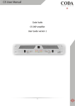
Coda Audio C475 Power Amplifier User Guide version 1.0 Contents EC Declaration of Conformity Important Safety Instructions Installation Electrical Mechanical EMC (RF Emissions) General Information Power Reduction Circuit (PRC) and Impedance Sensing Connections Inputs 3 4 4 4 5 5 5 6 6 6 Input Link Switches 7 Level controls Limiters Level Indicators PRC indicators Temperature control Fault indicators 8 8 8 9 9 9 Outputs Operation Switching on Panel Controls and Indicators Maintenance Gain/Sensitivity Settings Air Filter Technical Specification 7 8 8 8 9 9 10 11 Note that all amplifiers* before serial number 7E70004 have a different wiring configuration for the input and output sockets. This will only affect the “Linked” or “Bridged” modes of operation. * Serial numbering for the C475 commenced with 6E7..... 2 C745 User Guide Version 1.0 C475 User Guide Version 1.0 3 Important Safety Instructions 1) 2) 3) 4) 5) 6) 7) 8) 9) Read these instructions. Keep these instructions. Heed all warnings. Follow all instructions. Do not block any ventilation openings and install in accordance with the manufacturer’s instructions. Unplug this apparatus during lightning storms or when unused for long periods of time. Clean only with a dry cloth. Do not use this apparatus near water; the apparatus shall not be exposed to dripping or splashing and no objects filled with liquids, such as vases shall be placed on the apparatus. Refer all servicing to qualified service personnel. Servicing is required when the apparatus has been damaged in any way, such as if the power-supply cord or plug is damaged, liquid has been spilled or objects have fallen into the apparatus, the apparatus has been exposed to rain or moisture, does not operate normally, or has been dropped. Installation Instructions Electrical This amplifier has been manufactured to comply with your local power supply requirements but, before connecting the unit to the supply, ensure that the voltage (printed on the rear panel) is correct. Make sure power outlets conform to the power requirements listed on the back of the unit. Damage caused by connecting to improper AC voltage is not covered by the warranty. Safety Warning Where a mains plug or appliance coupler is used as the disconnect device, it should remain readily operable. Where the amplifier is mounted in a rack and permanently connected to the mains, then the rack should be installed with a readily accessible connector or an all pole circuit breaker. This unit is fitted with a 3-wire power cord. For safety reasons the earth lead should not be disconnected in any circumstance. If ground loops are encountered, consult the section on ‘Input Connections’ later in this manual. The wiring colours are: 230 V Areas: Warning: Earth = Green and Yellow Neutral = Blue Live = Brown 120 V Areas: Earth = Green Neutral = White Live = Black To reduce the risk of fire or electric shock, do not expose this apparatus to rain or moisture. To avoid electrical shock do not remove covers. Refer all servicing to qualified personnel. Do not use this unit if the electrical power cord is frayed or broken. The power supply cords should be routed so that they are not likely to be walked on or pinched by items placed upon or against them, paying particular attention to cords and plugs and the point where they exit from the appliance. 4 C745 User Guide Version 1.0 Always operate the unit with the AC ground wire connected to the electrical system ground. Precautions should be taken so that the means of grounding of a piece of equipment is not defeated. Do not remove the lid. Removing the lid will expose you to potentially dangerous voltages. There are no user serviceable parts inside. Mechanical To ensure that this equipment performs to specification, it should be mounted in a suitable rack or enclosure as described below. Like all high power amplifiers, it should be kept away from other equipment which is sensitive to magnetic fields or RF radiation. Also, this amplifier may suffer a substantial reduction in performance if it is subjected to, or mounted close to, equipment which radiates high RF fields, such as power transmitters. When mounting the amplifier in a rack or enclosure, ensure that:1. The rear of the unit is adequately supported. The brackets which are supplied fit standard 19 inch (483mm) rack mounting systems. The front panel is not capable of supporting the front panel is not capable of supporting the unit on its own. 2. There is adequate ventilation. The cooling fans suck cool air in through the front and blow hot air out at the rear of the unit through the ventilating grills. If the air is not allowed to escape, overheating will occur. Take care when mounting other equipment in the same rack. 3. The rack unit has a separate earth connection (technical earth). Also see maintenance section page 9 EMC (RF Emissions) The high frequency resonant converters in the C Series amplifiers have been designed to have very low radio frequency (RF) emissions, which can cause interference with other equipment. In order to reduce the influence of this, Power Amplifiers should be mounted in a dedicated metal rack enclosure, which does not include equipment which may be sensitive to RF radiation, such as radio microphone receivers. GENERAL INFORMATION Your C475 power amplifier utilises proprietary designed load impedance sensing output circuitry, which enables the amplifier to drive the high voltage swings associated with speaker impedances of 8 ohms and above, but automatically switches to a high current/medium voltage output required by 4 ohm loads. Fan speed is varied as required to keep the amplifier within its temperature limits. Signal limiters are included to protect speakers from clipped signals. The amplifier includes full DC and short circuit protection to ensure trouble-free service even in ‘harsher’ environments. C475 User Guide Version 1.0 5 The C-Series introduces three user-controlled features previously not seen on Coda Audio amplifiers: Bar LED level indicators on the front panel. Power reduction control (PRC) User-settable gain/sensitivity (internal) Power Reduction Circuit (PRC) and Impedance Sensing There are two PRC circuits in the C475: one for channels A & B and one for channels B & C. When the amplifier is to be used with 4 Ohm speakers (or bridged mono into 8 Ohm) or if you want to reduce the maximum power to protect the speakers, then the PRC can be selected via the switches on the rear panel. Whenever an audio signal of medium amplitude is present on any channel and, if the speaker impedance on any of the channels is less than 5.5 ohms, then the Automatic Impedance Sensing circuit will set that pair of channels to the 4 Ohm position. Connections Note that all amplifiers before serial number 7E70004 have a different wiring configuration for the input and output sockets. This will only affect the “linked” or “bridged” modes of operation. Inputs The inputs are made via 3-pin XLR connectors, which are electronically balanced and should be connected via a high grade twin core screened cable, as follows: Pin 1 Screen (see note) Pin 2 +ve signal (hot) Pin 3 -ve signal (cold) Note: +ve and –ve denotes the phase of the signal The amplifier is designed to operate with fully balanced equipment and ground loops or loss of performance may be experienced if connected to unbalanced sources. If it is unavoidable however, the following wiring should be used. The cable should still be twin core plus screen. Pin 1 Pin 2 Pin 3 - 6 Screen - connected to the chassis of the unbalanced equipment - or left disconnected at the unbalanced end. +ve signal -ve signal C745 User Guide Version 1.0 Note: This amplifier is wired to the latest industry recommendations. PIN1 is connected directly to the chassis/mains earth. If ground loops (mains hum) are encountered remove the screen connection from the other end of the cable and leave it open circuit. If problems persist, consult your dealer/supplier. Do not tamper with or alter any ground (earth) connections inside the amplifier. For bridged operation use channels A & B (or C & D). Inputs should be connected to channel A (or C). Pressing the A/B link switch (or C/D link switch) on the rear panel connects B amplifier to the A input (or the D amplifier to the C input). Input Link Switches The three input link switches on the rear panel link the inputs of the channels to the one higher up the hierarchy ladder. So the following combinations can be achieved. A & B (input on A) A & B & C (input on A) A & B & C & D (input on A) B & C (input on B) B & C & D (input on B) C & D (input on C) This switching, together with internal crossover cards (optional extras) provides a wide variety of input connection options. Outputs The speaker outputs are via Neutrik™ Speakon connectors: 2-pole (NL2FC) or 4-pole (NL4FC) connectors can be used. Terminations (all connectors) are as follows: Pin +1 = +ve signal output Pin -1 = -ve signal output For ease of installing bi-amped or bridged speakers, output connector A also carries output B and output connector C also carries output D. The terminations are as follows: Output connector A Pin +1 = +ve channel A Pin +2 = +ve channel B Pin -1 = -ve channel A Pin -2 = -ve channel B Output connector C Pin +1 = +ve channel C Pin +2 = +ve channel D Pin -1 = -ve channel C Pin -2 = -ve channel D For bi-amped operation connect as above. For bridged operation connect as follows: Channels A & B +ve = channel B +ve (pin +1 on connector B or +2 on connector A) -ve = channel A –ve (pin -1 on connector A) Channels C & D +ve = channel D +ve (pin +1 on connector D or +2 on connector C) -ve = channel C –ve (pin -1 on connector C) Note: Both level controls must be set to the same position. When operating in bridged mode, the minimum impedances are 8 Ohm. C475 User Guide Version 1.0 7 Note: 1. Negative (-ve) output terminals must not be joined together, since they are not both at 0V. 2. Because the currents involved are very high, the speaker cables should conform to the following minimum requirements, otherwise the losses will cause the cables to get hot and audio power will be reduced: C475 - 14 A into 4 Ohm speaker loads. 3. Do not connect the inputs/outputs to any other voltage source such as a battery, mains source or power supply, regardless of whether the amplifier is turned on or off. 4. Do not run the output of any amplifier channel back into another channel’s input and do not parallel or series-connect an amplifier output with any other amplifier output. Operation Switching on At ‘switch-on’ the protection circuit will initially activate whilst the circuits stabilise. Assuming no faults are detected after a few seconds, the red A/P LED will go off. Panel controls and indicators Level controls These are analogue controls allowing precise level settings. Note that in ‘BRIDGED’ mode, both level controls must be set to the same position. Limiters Each channel incorporates a high performance limiting circuit that prevents the outputs from ‘clipping’ when the maximum level is exceeded. They have been designed to be transparent to signals below this level and the attack and release times have been optimised for them to be unobtrusive when in operation. Level Indicators Each channel has an LED level ‘bar’, which shows green up to the -3 dB point, then orange and finally a red limit LED. Note the limit LED has a different response time to the others and with fast transients, can be ‘on’ even though some of the lower level LEDs are not. 8 C745 User Guide Version 1.0 PRC Indicators (green LED) These indicate when the PRC circuit, for the specific pair of channels, has been selected. (Either manually via the switches on the rear panel or automatically via the impedance sensing circuit) Temperature Control The cooling fans respond to temperature sensors within the unit to maintain a safe operating temperature. In the event of excessive temperature, the protection circuit will operate, disabling the output. The red ‘AUDIO-PROTECT’ (A/P) LED will indicate this condition. (See fault indicator). There are 4 fans connected permanently with variable speed and a jumper link to enable them from cold. Normal dynamic signals will not cause the amplifier to overheat unless the ventilation is inadequate. (See installation section and maintenance section.) Fault Indicator (Audio Protection – red LED) If the outputs are shorted or if DC is present, the protection circuit will disengage the outputs and the A/P LED will illuminate. The amplifier will continue to be monitored and depending on the type of fault, will either reset after the fault has cleared or require manual resetting by switching off at the mains switch and then on again after a few seconds. (See also temperature control above.) Maintenance Caution: These servicing instructions are for use by qualified personnel only. Ensure that electrical power to the unit is disconnected before carrying out any maintenance. Gain/Sensitivity Settings Gain settings are changed internally by simple jumper links. Four rows of pins marked: - GAIN A, GAIN B, GAIN C and GAIN D - are situated on the input PCB (PCB721). A jumper link sets the gain and the settings are as follows: Link 1 & 2 Link 3 & 4 Link 2 & 3 Note: gives gives gives 32 dB gain 26 dB gain approx. 31 dB gain = 6 dBu/1.5 V sensitivity into 4 Ohm Factory setting is normally link 1 & 2 = 32dB gain. Setting higher gain does not change the maximum available power but changes the level of signal input to achieve maximum power. In any case, provided that the input signal is less than 20 dBu/7.7 V, the built in limiter circuit will prevent distortion within the amplifier. The gain should be set to match the signal from the source, e.g. mixer, controller, equaliser etc. C475 User Guide Version 1.0 9 Air filter The filter behind the air intake apertures on the front of the C475 amplifier should be cleaned or replaced periodically, e.g. 3-6 months. (Filters in amplifiers located in more 'dirty' atmospheres may require more frequent maintenance.) Access is via the blue front panel. The filter should be 'dry' cleaned, using a vacuum cleaner preferably. Running the unit without a filter is not recommended unless it is within a 'clean room'. Replacement filter material is available. No other regular maintenance is required. If you have any doubt about carrying out this procedure, refer to a service engineer or contact your dealer. If your amplifier develops a fault, please refer to your supplier for service and technical support. Do not attempt to repair the fault yourself as this will invalidate the warranty. 10 C745 User Guide Version 1.0 Technical Specification Output power (Watts RMS) per channel 8 Ohm @ 1 kHz 4 Ohm @ 1 kHz 750 825 THD @ rated power 8 Ohm 1 kHz 20 Hz-20 kHz <0.006 % <0.03 % Input CMRR >70 dB Hum & Noise -105 dB Gain (selectable) +32 dB/+26 dB/+31 dB Sensitivity for rated output, 4 Ohm +5 dBu/+11 dBu/+6 dBu (1.5 V) Damping Factor 1 kHz, 8 Ohm >400 Frequency response 20 Hz-20 kHz - +0/0.5 dB Input impedance (actively balanced) 20 kOhm Dimensions (mm) - 2U 88 x 482 x 428 Weight 10.25 kg Power requirement*** 230 VAC @ 15 Amps maximum 115 VAC @ 30 Amps maximum *** Using dynamic signals, even the most demanding music, all four channels driven to the limit level, then the average power consumption is: 230 VAC @ 9 Amps or 115 VAC @ 18 Amps These figures can conservatively be used when calculating air conditioning/ventilation requirements. An internal link can be set to either 100 V or 120 V for the 115 V version and 220 V or 240 V for the 230 V version. Normally these are set to 120 V and 240 V respectively. This amplifier will only operate to its very high specification if it is installed and operated as described in this manual. C475 User Guide Version 1.0 11 Coda Audio GmbH Boulvard der EU 6 30539 Hannover Germany Phone: +49 (0) 511 – 866 55 888 Fax: +49 (0) 511 – 866 55 887 E-Mail: [email protected] Website: www.codaaudio.com