1
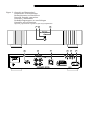
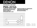
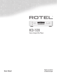
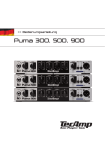
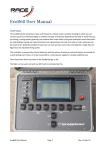
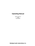
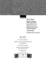
Owner’s Manual
Manuel d’utilisation
Bedienungsanleitung
Manuale di Istruzioni
Manual de Instrucciones
Gebruiksaanwijzing
Instruktionsbok
Инструкция По Эксплуатации
RB-1091
Mono Power Amplifier
Amplificateur de Puissance Monophonique
Mono-Endstufe
Finale di Potenza Mono
Etapa de Potencia Monofónica
Mono Eindversterker
Monoslutsteg
Моно усилитель мощности
RB-1091 Mono Power Amplifier
2
Important Safety Information
WARNING: There are no user serviceable parts inside. Refer
all servicing to qualified service personnel.
WARNING: To reduce the risk of fire or electric shock, be
sure that the apparatus shall not be exposed to dripping
or splashing and that no objects filled with liquids, such as
vases, shall be placed on the apparatus.
Do not allow foreign objects to get into the enclosure. If the
unit is exposed to moisture, or a foreign object gets into the
enclosure, immediately disconnect the power cord from the
wall. Take the unit to a qualified service person for inspection
and necessary repairs.
Read all the instructions before connecting or operating the component.
Keep this manual so you can refer to these safety instructions.
Heed all warnings and safety information in these instructions and on the
product itself. Follow all op erating instructions.
Clean the enclosure only with a dry cloth or a vacuum cleaner.
You must allow 10 cm or 4 inches of unobstructed clearance
around the unit. Do not place the unit on a bed, sofa, rug, or similar
surface that could block the ventilation slots. If the component is placed in
a bookcase or cabinet, there must be ventilation of the cabinet to allow
proper cooling.
Keep the component away from radiators, heat registers, stoves, or any
other appliance that produces heat.
The unit must be connected to a power supply only of the type and voltage
specified on the rear panel of the unit.
Connect the component to the power outlet only with the supplied power
supply cable or an exact equivalent. Do not modify the supplied cable in any
way. Do not attempt to defeat grounding and/or polarization provisions.
Do not use extension cords.
Do not route the power cord where it will be crushed, pinched, bent at severe
angles, exposed to heat, or damaged in any way. Pay particular attention
to the power cord at the plug and where it exits the back of the unit.
Main plug is used as the mains disconnect device and shall remain ready
accessible.
The power cord should be unplugged from the wall outlet if the unit is to
be left unused for a long period of time.
Immediately stop using the component and have it inspected and/or serviced
by a qualified service agency if:
• The power supply cord or plug has been damaged.
• Objects have fallen or liquid has been spilled into the unit.
• The unit has been exposed to rain.
• The unit shows signs of improper operation
• The unit has been dropped or damaged in any way
Please use Class 2 Wiring when connecting the speaker terminals of the unit
to ensure proper insulation and minimize the risk of electrical shock.
Place the unit on a fixed, level surface strong enough to
support its weight. Do not place it on a moveable cart
that could tip over.
This symbol means that this unit is double
insulated. An earth connection is not
required.
Rotel products are designed to comply with international
directives on the Restriction of Hazardous Substances (RoHS) in
electrical and electronic equipment and the disposal of Waste
Electrical and Electronic Equipment (WEEE). The crossed
wheelie bin symbol indicates compliance and that the products
must be appropriately recycled or processed in accordance
with these directives.
English
3
Figure 1: Controls and Connections\
Commandes et branchements
Bedienelemente und Anschlüsse
Pannello frontale e posteriore
Controles y Conexiones
De bedieningsorganen en aansluitingen
Kontroller och anslutningar
Органы управления и разъемы для подсоединения
�
��
�
�
�
� �
�
RB-1091 Mono Power Amplifier
4
Figure 2: Input and Output Connections
Anschlussdiagramm
Prises d’entrées et de sorties
Schema di collegamento
Conexiones de Entrada y de Salida
De in- en uitgangsaansluitingen
In- och utgångar
Подключение входов и выходов
Important Notes
When making connections be sure to:
✔ Turn off all the components in the system before hooking up any components, including loudspeakers.
✔ Turn off all components in the system before changing
any of the connections to the system.
It is also recommended that you:
✔ Turn the volume control of the amplifier all the way down
before the amplifier is turned on or off.
�������������������������
�����
������
����
������
Single Wire Connection
Biwire Connection
��
See page 7 for information on using the Speakon® speaker output connectors.
��
English
5
Contents
About Rotel
Important Safety Information ................. 2
Figure 1: Controls and Connections
3
Figure 2: Input and Output Connections
4
About Rotel ........................................... 5
Getting Started ...................................... 5
Operating Features
5
A Few Precautions
5
Placement
5
AC Power and Control ............................ 6
AC Power Input 9
6
Power Switch and Indicator 12
6
Turn On/Off Mode Selector 7
6
+12V Trigger Input and Output 8
6
Protection Indicators 3 ........................ 6
Input Signal Connection 4..................... 6
Speaker Connection ................................ 7
Speaker Selection
7
Speaker Wire Selection
7
Polarity and Phasing
7
Conventional Speaker Wire Connections 5 7
Speakon® Speaker Connection 6
7
Troubleshooting...................................... 8
Front Panel Power Indicator Is Not Lit
8
No Sound
8
Protection Indicator Is Lit
8
Specifications ......................................... 8
A family whose passionate interest in music led
them to manufacture high fidelity components
of uncompromising quality founded Rotel over
40 years ago. Over the years that passion
has remained undiminished and the goal of
providing exceptional value for audiophiles
and music lovers regardless of their budget,
is shared by all Rotel employees.
The engineers work as a close team, listening
to, and fine tuning each new product until it
reaches their exacting musical standards. They
are free to choose components from around the
world in order to make that product the best
they can. You are likely to find capacitors from
the United Kingdom and Germany, semiconductors from Japan or the United States, and
toroidal power transformers manufactured in
Rotel’s own factory.
Rotel’s reputation for excellence has been
earned through hundreds of good reviews and
awards from the most respected reviewers in
the industry, who listen to music every day.
Their comments keep the company true to its
goal – the pursuit of equipment that is musical,
reliable and affordable.
All of us at Rotel thank you for buying this
product and hope it will bring you many hours
of enjoyment.
Getting Started
Thank you for purchasing the Rotel RB-1091
Mono Power Amplifier. When used in a highquality music or home theater system, your
Rotel amplifier will provide years of musical
enjoyment.
The RB-1091 is a sophisticated single-channel
power amplifier. It’s digital amplifier circuitry,
switching power supply, premium components,
and Rotel’s Balanced Design ensure superb
sound quality. High current capability allows
the RB-1091 to drive difficult speaker loads
with ease.
Operating Features
• Single channel amplifier.
• User selectable power on/off configuration:
manual or controlled by remote 12 volt
trigger signal.
• Protection circuitry with front panel indicator.
• Dual binding post and Speakon® speaker
output.
A Few Precautions
Please read this manual carefully. In addition to
installation and operating instructions, it provides information on various RB-1091 system
configurations. Please contact your authorized
Rotel dealer for answers to any questions you
might have. In addition, all of us at Rotel welcome your questions and comments.
Save the RB-1091 shipping carton and packing
material for future use. Shipping or moving the
RB-1091 in anything other than the original
packing material may result in severe damage
to your amplifier.
Be sure to keep the original sales receipt. It is
your best record of the date of purchase, which
you will need in the event warranty service is
ever required.
Placement
The RB-1091 generates heat as part of its
normal operation. The heat sinks and ventilation openings in the amplifier are designed to
dissipate this heat. The ventilation slots in the
top cover must be unobstructed. There should
be 10 cm (4 inches) of clearance around the
chassis, and reasonable airflow through the
installation location, to prevent the amplifier
from overheating. Likewise, remember the
weight of the amplifier when you select an
installation location. Make sure that the shelf
or cabinet can support its weight.
RB-1091 Mono Power Amplifier
AC Power and Control
AC Power Input
9
The RB-1091 is supplied with the proper AC
power cord. Use only this cord or an exact
equivalent. Do not use an extension cord. A
heavy duty multi-tap power outlet strip may
be used, but only if it is rated to handle the
current demand of the RB-1091.
Be sure the Power Switch on the front panel of
the RB-1091 is turned off. Then, plug one end
of the cord into the AC power connector 9 on
the back panel of the amplifier. Plug the other
end into an appropriate AC outlet.
Your RB-1091 is configured at the factory for the
proper AC line voltage in the country where you
purchased it (USA: 120 volts/60 Hz, Europe:
230 volts/50 Hz). The AC line configuration is
noted on a label on the back panel.
NOTE: Should you move your RB-1091 to
another country, it is possible to configure
your amplifier for use on a different line
voltage. Do not attempt to perform this conversion yourself. Opening the enclosure of
the RB-1091 exposes you to dangerous voltages. Consult a qualified technician or the
Rotel factory service department for information.
If you are going to be away from home for
an extended period of time, it is a sensible
precaution to unplug your amplifier.
Power Switch and
Indicator 12
The Power Switch is located on the front panel.
To turn the amplifier on (or to activate either of
the optional automatic power-on modes), push
the switch in. The LED indicator above the switch
will light, indicating that the amplifier is turned
on. To turn the amplifier off, push the button
again and return it to the out position.
6
Turn On/Off Mode Selector
7
The RB-1091 can be turned on and off automatically by using its “12V Trigger” system.
The Turn On/Off Mode Selector switch is used
to select which method is used.
• With the switch in the OFF position, the
amplifier is turned on or off manually using
the front panel power switch.
• With the switch in the 12V TRIG. position,
the amplifier is turned on automatically
when a 12 volt trigger signal is applied to
the 3.5mm Jack labeled IN. The front panel
POWER SWITCH overrides this function. It
must be ON for the +12V trigger to work.
Turning the switch OFF cuts power to the
amplifier, regardless of whether or not a
trigger signal is present.
+12V Trigger Input
and Output 8
The jack labeled IN is for connecting the 3.5mm
Plug/Cable carrying a +12 volt trigger signal
to turn the amplifier on and off. To use this
feature the adjacent switch 7 must be set in
the 12V TRIG position (see previous section).
This input accepts any control signal (AC or
DC) ranging from 3 volts to 30 volts.
The jack labeled OUT is for connecting another
3.5mm plug/cable to provide a 12V trigger
signal to other components. The 12V output
signal is available whenever a +12 volt trigger
signal is applied to the IN connector.
Protection Indicators 3
Thermal and protection circuits protect the amplifier against potential damage in the event of
extreme or faulty operating conditions. Unlike
many designs, the RB-1091’s protection circuit
is independent of the audio signal and has
no impact on sonic performance. Instead, the
protection circuit monitors the temperature of
the output devices and shuts down the amplifier
if safe limits are exceeded.
In addition, the RB-1091 includes overcurrent
protection which operates only when load
impedances drop too low.
Should a faulty condition arise, the amplifier
will stop playing and the PROTECTION LED
on the front panel will light.
If this happens, turn the amplifier off, let it
cool down for several minutes, and attempt to
identify and correct the problem. When you
turn the amplifier back on, the protection circuit
will automatically reset and the PROTECTION
LED should go out.
In most cases, the protection circuitry activates
because of a fault condition such as shorted
speaker wires, or inadequate ventilation leading to an overheating condition. In very rare
cases, highly reactive or extremely low impedance speaker loads could cause the protection
circuit to engage.
Input Signal Connection 4
See Figure 2
The RB-1091 has a standard unbalanced RCAtype input connector, the type used on nearly all
audio equipment. This RCA input accept audio
signals from preamplifiers or surround sound
processors. Use high quality audio interconnect
cables for best performance.
English
7
Speaker Connection
See Figure 2
Conventional Speaker Wire
Connections 5
The RB-1091 has two sets of dual binding post
speaker connection terminals. In addition there
is a four-contact Speakon® connector. Some
speakers also have Speakon® connectors
which make it easy to connect the speakers by
simply plugging in wires that are terminated
with Speakon® plugs. Even if your speakers
do not have Speakon® connectors you can still
use speaker wires that have Speakon® plugs
on one end.
Route the wire(s) from the RB-1091 to the
speakers. Give yourself enough slack so you
can move the components to allow access to
the speaker connectors.
Speaker Selection
The nominal impedance of the loudspeaker(s)
connected to the RB-1091 should be no lower
than 4 ohms.
Speaker Wire Selection
Use insulated two-conductor stranded wire to
connect the RB-1091 to the speakers. The size
and quality of the wire can have an audible effect on the performance of the system. Standard
speaker wire will work, but can result in lower
output or diminished bass response, particularly
over longer distances. In general, heavier wire
will improve the sound. For best performance,
you may want to consider special high-quality
speaker cables. Your authorized Rotel dealer
can help in the selection of appropriate cables
for your system.
Polarity and Phasing
The polarity – the positive/negative orientation
of the connections – for every speaker and
amplifier connection must be consistent so all
the speakers will be in phase. If the polarity
of one connection is mistakenly reversed, bass
output will be very weak and stereo imaging
degraded. All wire is marked so you can
identify the two conductors. There may be ribs
or a stripe on the insulation of one conductor.
The wire may have clear insulation with different color conductors (copper and silver).
There may be polarity indications printed on
the insulation. Identify the positive and negative conductors and be consistent with every
speaker and amplifier connection.
If you are using Speakon® plugs be sure the
wires are connected to the proper terminals
on the plug.
The RB-1091 has two sets of color coded
terminals. Having two sets of terminals makes
it easy to biwire a speaker. The speaker
terminals accept bare wire, connector lugs,
or “banana” type connectors (except in the
European Community countries where their
use is not permitted).
If you are using banana plugs, connect them
to the wires and then plug into the backs of the
speaker connectors. When using banana plugs,
the collars of the binding post terminals should
be screwed in all the way (clockwise).
If you are using terminal lugs, connect them
to the wires. If you are attaching bare wires
directly to the speaker connectors, separate the
wire conductors and strip back the insulation
from the end of each conductor. Be careful
not to cut into the wire strands. Unscrew (turn
counterclockwise) the binding post collar. Place
the connector lug around the shaft, or insert
the bundled wire into the hole in the shaft. Turn
the collars clockwise to clamp the connector
lug or wire firmly in place.
NOTE: Be sure there are no loose wire
strands that could touch adjacent wires or
connectors.
Speakon® Speaker
Connection 6
The RB-1091 has a four-contact Speakon®
speaker connector. The four contact connectors
make it easy to make biwire speaker connections. The connector on the RB-1091 also accepts two contact Speakon® connectors if you
do not plan to biwire the speakers.
Pre-wired Speakon® connector cables are
available. You may also wire your own cables
using wire you choose.
Wiring Speakon® Connectors
This information describes how to wire the
NL4FC four-contact Speakon® connector. The
NL2FC two-contact connector is connected
in a similar way. See the instruction sheet
that comes with the connector for more information, or go the manufacturer’s web site,
www.neutrik.com.
Place the bushing and
chuck on the cable as
shown before attaching
the wires to the terminals
on the insert.
Remove the outer jacket
of the wire and strip the
insulation from the wires
as shown. Twist the wire
strands together and insert
it into the terminal. Tighten
the terminal screw with a
screw driver or a 1/16”
allen wrench to clamp the
cable wire in place.
The insert terminals are
labeled 1+, 1–, 2+ and
2–. Connect the wires to
the terminals of the connector insert for the other
end of the cable before you
assemble the connectors so
you can be sure that each
wire is connected to the
corresponding terminal on
each insert.
Push the insert all the way
into the housing. Slide the
chuck down the wire into
place behind the insert.
Thread the bushing onto
the housing and tighten
it so the chuck clamps the
cable in place.
�������
�����
������
�������
RB-1091 Mono Power Amplifier
Troubleshooting
Most difficulties in audio systems are the result of
poor or wrong connections, or improper control
settings. If you encounter problems, isolate the
area of the difficulty, check the control settings,
determine the cause of the fault and make the
necessary changes. If you are unable to get
sound from the RB-1091, refer to the suggestions for the following conditions:
Front Panel Power Indicator Is
Not Lit
No main power to the RB-1091. Check AC
power connections at the amplifier and the
AC outlet. Check the front panel power switch.
Make sure that it is set to the ON position. If
using 12V trigger power-on, make sure that
a trigger signal is present at rear panel 12V
TRIG IN jack.
No Sound
If the amp is getting AC power, but is producing
no sound, check the PROTECTION INDICATOR
on the front panel. If lit, see below. If not, check
all of your connections and control settings on
associated components. Make sure that your
input connections and speaker connections
match your system configuration.
Protection Indicator Is Lit
The front panel PROTECTION INDICATOR
will light when the RB-1091 protection circuits
have shut off the amplifier. Typically, this occurs only when the amplifier has overheated,
when there is faulty speaker wiring, or after
a period of extreme use. Turn off the system
and wait for the amp to cool. Then push the
front panel power switch in and out to reset
the protection devices. If the problem is not
corrected or reoccurs, there is a problem with
the system or the amplifier itself.
8
Specifications
Power Configurations
1 x 500 Watts
Watts/Channel
500 watts, with 20KHz filter, 8 ohm load,
20-20 kHz, 0.03% THD
Total Harmonic Distortion (20Hz-20kHz, 8 ohms)
Continuous Rated Power
< 0.03%
One-Half Rated Power
< 0.03%
One Watt per Channel
< 0.03%
Power Output (4 Ohms, 0.09% THD)
1000 watts
Output Peak Current
40A
Intermodulation Distortion 60 Hz:7 kHz, 4:1
< 0.03%
Damping Factor (8 ohms)
400
Amp Gain
27.2dB
Input Sensitivity/Impedance
2.2 V / 11.1 k ohms
Frequency Response
10 - 40 KHz (±3dB)
Signal to Noise Ratio (IHF A)
118 dB
Power Requirements
USA
Europe
Power Consumption
120 Volts, 60 Hz
230 Volts, 50 Hz
300 Watts
34 Watts - Idling
3 Watts - Standby
Dimensions (W x H x D)
432 x 92 x 407 mm
17 1/8 x 35/8 x 16 1/8 in
Panel Height (for rack mounting)
80 mm, 31/8 in
Weight (net)
7.8 kg, 17.2 lb.
All specifications are accurate at the time of printing.
Rotel reserves the right to make improvements without notice.
The Rotel Co. Ltd.
10-10 Shinsen-Cho
Shibuya-Ku
Tokyo 150-0045
Japan
Phone: +81 3-5458-5325
Fax: +81 3-5458-5310
Rotel of America
54 Concord Street
North Reading, MA 01864-2699
USA
Phone: +1 978-664-3820
Fax: +1 978-664-4109
Rotel Europe
Dale Road
Worthing, West Sussex BN11 2BH
England
Phone: + 44 (0)1903 221 761
Fax: +44 (0)1903 221 525
Rotel Deutschland
Vertrieb: B&W Group Germany GmbH
Kleine Heide 12
D-33790 Halle/Westf., Deutschland
Tel.: 05201 / 87170
Fax: 05201 / 73370
E-Mail: [email protected]
www.rotel-hifi.de
www.rotel.com
082 OMRB1091 021206
English • French • Deutsch • Italiano • Español • Nederlands • Svenska • Русский