1
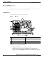
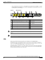
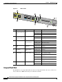
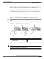
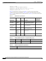
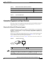
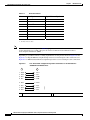
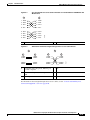
CH A P T E R
6
NPE-G2 Overview
This chapter describes the NPE-G2 and contains the following sections:
Caution
•
Supported Platforms, page 6-1
•
Software Requirements, page 6-2
•
NPE-G2 Description and Overview, page 6-2
•
NPE-G2 Memory Information and Specifications, page 6-11
•
Fiber Optic Cleaning Information, page 6-23
You must copy and save your running configuration file to a CompactFlash Disk, PC Card, or TFTP
server before you install the NPE-G2. For instructions on copying and saving your configuration file, see
the “Copying the Configuration File” section on page 7-4 in Chapter 7, “NPE-G1 and NPE-G2
Installation and Configuration Information.”
For general preparation for installation instructions, see Chapter 8, “Preparation for Installation.” For
installation and configuration instructions specific to the NPE-G2, see Chapter 7, “NPE-G1 and NPE-G2
Installation and Configuration Information.”
Supported Platforms
The NPE-G2 is supported on the Cisco 7200 VXR routers and Cisco uBR7200 series routers. For the
Cisco 7200 VXR routers, order Part Number NPE-G2 or NPE-G2=. For the Cisco uBR7200 series
routers, order Part Number UBR7200-NPE-G2 or UBR7200-NPE-G2=.
Note
Unless otherwise indicated, all references to NPE-G2 in this document also refer to UBR7200-NPE-G2.
Network Processing Engine and Network Services Engine Installation and Configuration
OL-4448-12
6-1
Chapter 6
NPE-G2 Overview
Software Requirements
Software Requirements
For minimum software release information, see the “Software Requirements” section on page 8-4.
Note
The NPE-G2 has its own Cisco IOS software image with the prefix “c7200p-” in the software images
filenames, including the boot image. The NPE-G2 does not boot up with a software image with the prefix
“c7200-”. Previous network processing engines, or the network services engine, do not boot up with the
“c7200p-” boot image. They use the prefix “c7200-”.
NPE-G2 Description and Overview
This section contains information about the NPE-G2 components and the system management functions.
The following information is in this section:
•
Bandwidth Requirements, page 6-3
•
Components, page 6-3
•
Interfaces, page 6-4
•
LEDs, page 6-5
•
CompactFlash Disk, page 6-6
•
USB Ports, page 6-8
•
Summary of Important NPE-G2 Information, page 6-9
•
System Management Functions, page 6-10
•
Terms and Acronyms, page 6-10
Like the NPE-G1, the NPE-G2 provides the functionality of both a network processing engine and I/O
controller. If used without an I/O controller, an I/O controller blank panel must be in place.
While its design provides I/O controller functionality, it can also work with any I/O controller supported
in the Cisco 7200 VXR routers or Cisco uBR7200 series routers. The NPE-G2, when installed with an
I/O controller, provides the bootflash and NVRAM that the Cisco IOS software uses to boot.
Note
An I/O controller can be used with the NPE-G2, but an I/O controller is not necessary for system
functionality. Installing an I/O controller in a chassis with the NPE-G2 activates the console and
auxiliary ports on the I/O controller and automatically disables the console and auxiliary ports on the
NPE-G2. However, you can still use the CompactFlash Disk slots and Ethernet ports on both the NPE-G2
and I/O controller when both cards are installed.
The NPE-G2 maintains and executes the system management functions for the Cisco 7200 VXR routers
and Cisco uBR7200 series routers and also holds the system memory and environmental monitoring
functions. The NPE-G2 consists of one board with multiple interfaces.
The NPE-G2 can be used with the Port Adapter Jacket Card installed in the I/O controller slot. If you
are upgrading to an NPE-G2 and Port Adapter Jacket Card at the same time, see the Port Adapter Jacket
Card Installation Guide for information about the order of installation of both the NPE-G2 and the Port
Adapter Jacket Card.
Network Processing Engine and Network Services Engine Installation and Configuration
6-2
OL-4448-12
Chapter 6
NPE-G2 Overview
NPE-G2 Description and Overview
Bandwidth Requirements
The Gigabit Ethernet ports on the NPE-G2 do not use bandwidth points, nor does the Fast Ethernet
management port. When used with any I/O controller, the Ethernet ports, Fast Ethernet ports, or Gigabit
Ethernet ports on the I/O controller also do not use bandwidth points.
Components
Figure 6-1 illustrates the NPE-G2 and its major components.
Figure 6-1
NPE-G2
1
10
9
2
8
4
3
5
7
149061
6
1
Midplane connectors
6
Flash memory (U13)
2
Boot ROM (U24)
7
DIMM (socket—S1)
3
NVRAM (on bottom of board—U17)
8
Temperature sensor (inlet—U23)
4
Temperature sensor (outlet—U20)
9
Processor (U30)
5
Flash memory (U19)
10 Keying post
The NPE-G2 consists of the following components:
•
Motorola Freescale 7448 processor
– Microprocessor operates at an internal clock speed of 1.67 GHz.
– Hardware logic to interconnect the processor, double data rate synchronous dynamic
random-access memory (DDR-SDRAM), lightning data transport (LDT) bus, the generic PCI
bus, and three direct-interface Gigabit Ethernet interfaces.
Network Processing Engine and Network Services Engine Installation and Configuration
OL-4448-12
6-3
Chapter 6
NPE-G2 Overview
NPE-G2 Description and Overview
•
Cache memory
The NPE-G2 has two levels of cache: primary and secondary cache that are internal to the
microprocessor with secondary unified cache for data and instruction.
•
The NPE-G2 uses DDR SDRAM for providing code, data, and packet storage.
•
Two environmental sensors for monitoring the cooling air as it enters and leaves the chassis.
•
Full-feature I/O controller functionality
– Three Gigabit Ethernet interfaces (six ports: three SFP [optical] and three RJ-45s [copper]).
Any three ports are available at the same time and are linked directly to the processor; therefore
the interfaces are not charged bandwidth points.
– CompactFlash Disk for storing the default Cisco IOS software image. The CompactFlash Disk
slot can be used whether or not an I/O controller is in the router.
– Auxiliary port with full data terminal equipment (DTE) functionality. (Functional when an I/O
controller is not present. If an I/O controller is present, its auxiliary port is the default port.)
– Console port with full data communications equipment (DCE) functionality. (Functional when
an I/O controller is not present. If an I/O controller is present, its console port is the default
port.)
– Dedicated 10/100 Fast Ethernet Management port—Not to be used for any other purpose.
– Two USB ports for data storage using Cisco USB flash memory modules or security eToken for
VPN applications.
– Boot ROM for storing the ROMmon images.
– Internal flash memory for storing the boot helper (boot loader) image and the Cisco IOS image.
(The boot helper image comes installed on the NPE-G2.) If an I/O controller is present, its
internal flash memory is no longer available.
– NVRAM for storing the system configuration and environmental monitoring logs. NVRAM
uses lithium batteries to maintain its contents when disconnected from power. If an I/O
controller is present, its NVRAM memory is no longer available.
– Upgradable memory module
Note
An I/O controller can be used with the NPE-G2, but an I/O controller is not necessary for
system functionality. Installing an I/O controller in a chassis with the NPE-G2 activates the
console and auxiliary ports on the I/O controller and automatically disables the console and
auxiliary ports on the NPE-G2. However, you can still use the Compact Flash Disk slots and
Ethernet ports on both the NPE-G2 and I/O controller when both cards are installed.
Interfaces
The three interfaces on the NPE-G2 consist of three small form-factor (SFP) Gigabit Ethernet ports and
three 10/100/1000 Fast Ethernet/Gigabit Ethernet ports. The rules for using these ports are:
•
Only one port per interface can be used at any one time. For example, for interface
Gigabit Ethernet 0/1, either the RJ-45 port can be used or the SFP port, but not both.
•
A total of three ports on any of the three interfaces (0/1, 0/2, or 0/3) can be used at any one time; for
example, 0/1 SFP, 0/2 SFP, and 0/3 RJ-45.
Network Processing Engine and Network Services Engine Installation and Configuration
6-4
OL-4448-12
Chapter 6
NPE-G2 Overview
NPE-G2 Description and Overview
•
The port numbering for the interfaces on the NPE-G2 starts with 0/1 and not with 0/0, as is typical
for other interface cards. This is to avoid conflicts with the Ethernet and Fast Ethernet ports on an
I/O controller, if it is also installed.
Figure 6-2
NPE-G2 Interfaces
2
4
GIGABIT ETHERNET 0 / 1
6
GIGABIT ETHERNET 0 / 2
LINK
ACTV
8
10
11
NETWORK PROCESSING ENGINE - G2
GIGABIT ETHERNET 0 / 2
LINK
ACTV
LINK
ACTV
FE
LINK
NPE-G2
CPU
RESET
EN
EN
RJ45
EN
RJ45
13
COMPACT FLASH
U
S
B
CF
ACTV
USB
RJ45
CONSOLE
AUX
FE 0/2
SYST
STAT
PWR
OK
1
3
5
7
9
12
1
CPU Reset
8
Console port
2
Fast Ethernet/Gigabit Ethernet RJ-45 port—GE 0/1
9
Auxiliary port
3
Gigabit Ethernet port—GE 0/1
10 Fast Ethernet Management
port—FE 0/2
4
Fast Ethernet/Gigabit Ethernet RJ-45 port—GE 0/2
11 USB port 0
5
Gigabit Ethernet port—GE 0/2
12 USB port 1
6
Fast Ethernet/Gigabit Ethernet RJ-45 port—GE 0/3
13 CompactFlash Disk slot
7
Gigabit Ethernet port—GE 0/3
149062
FOR MANAGEMENT
USE ONLY
Note
The Fast Ethernet Management RJ-45 port is only used for management activities—not for any other
purpose.
Note
The USB function is not supported on Cisco uBR7200 series routers.
LEDs
This section provides information about the location and behavior of the NPE-G2 LEDs.
The NPE-G2 faceplate contains LEDs that indicate system and port status. The RJ-45 and SFP ports
share the same LINK ACTV LED because only one of these ports per interface (0/1, 0/2, or 0/3) can be
used at any one time. The EN (Enable) LED is on if the RJ-45 port is in use.
The PWR OK LED is on whether or not an I/O controller is present in the router. The CompactFlash
Disk slot can be used whether or not an I/O controller is present in the router. The SYST STAT LED
provides information about the status of the system.
Network Processing Engine and Network Services Engine Installation and Configuration
OL-4448-12
6-5
Chapter 6
NPE-G2 Overview
NPE-G2 Description and Overview
Figure 6-3
NPE-G2 LEDs
1
GIGABI
T ETHE
RNET 0
LINK
ACTV
3
/3
5
FE
LINK
E
AUX
FE 0/2
FOR MA
NAGE
USE ON MENT
LY
2
NETWO
RK PRO
CESSIN
G ENGIN
COMPA
E - G2
CT
U
S
B
CONSOL
USB
6
FLASH
CF
ACTV
149063
EN
RJ45
SYST
STAT
PWR
OK
4
7
Table 6-1
No.
LED Label
1
2
3
4
5
6
Color
Description
LINK ACTV
RJ-45 and SFP
(Interfaces 0/1, 0/2, ports
0/3)
Solid green
Link with no activity
Flashing green
Link with activity
Off
No link
EN (Enable)
RJ-45 ports only
(Interfaces 0/1, 0/2,
0/3)
Solid green
RJ-45 port is selected.
Off
SFP port is selected.
FE LINK
Solid green
Link with no activity
Flashing green
Link with activity
Off
No link
Flashing green
Activity
Off
No activity
CompactFlash
Disk
Flashing green
Activity
Off
No activity
System status
Blinking green
Cisco IOS is loading.
Solid green
Cisco IOS has successfully
booted.
USB
CF ACTV
SYST STAT
LED
Fast Ethernet
Management port
USB ports
Blinking yellow ROMmon is loading.
7
PWR OK
Power
Solid yellow
ROMmon has successfully
booted.
Green
The NPE-G2 has powered on.
Off
No activity
CompactFlash Disk
The NPE-G2 has one CompactFlash Disk slot that uses CompactFlash Disks. The device in this slot is
always addressed as disk2: when using Cisco IOS CLI commands.
Network Processing Engine and Network Services Engine Installation and Configuration
6-6
OL-4448-12
Chapter 6
NPE-G2 Overview
NPE-G2 Description and Overview
CompactFlash Disks are smaller in size than Type 2 Flash Disks but provide the same Attachment (ATA)
interface and equivalent functionality. This interface complies with the ANSI ATA Interface Document
X3T13.1153 D Rev. 9 specification. The CompactFlash Disk provides 256 MB of storage space.
The CompactFlash Disk has controller circuitry that allows it to emulate a hard disk and automatically
maps out bad blocks and performs automatic block erasure. The CompactFlash Disk also provides the
capability to allocate noncontiguous sectors, which eliminates the need for the squeeze command (which
was required with older-style linear flash memory cards to recover the space used by deleted files).
The CompactFlash Disk also supports the Cisco IOS File System feature, which provides a single
interface to all of the router’s file systems, including the Flash Disks and flash memory, as well as
network file systems such as File Transfer Protocol (FTP) and Trivial FTP (TFTP) servers.
Table 6-4 lists the CompactFlash Disk options.
To install a CompactFlash Disk in the CompactFlash Disk slot, complete the following steps
Step 1
Attach an ESD wrist or ankle strap, connecting the equipment end of the strap to an unfinished chassis
surface.
Step 2
Orient the CompactFlash Disk so that its connector end faces the appropriate slot. (See 1 in Figure 6-4.)
Figure 6-4
Installing and Removig a CompactFlash Disk
1
2
NETWOR
K PROC
ESSING
COMPAC
T FLAS
H
3
NETWOR
ENGINE
K PROC
T FLAS
NETWOR
ENGINE
H
CF
ACTV
K PROC
ESSING
COMPAC
T FLAS
- G2
H
ENGINE
- G2
CF
ACTV
149064
CF
ACTV
ESSING
COMPAC
- G2
1
Inserting the compact Flash Disk
2
Pressing the ejector button to release the
CompactFlash Disk
3
Removing the CompactFlash Disk
Step 3
Carefully insert the CompactFlash Disk into the slot until it completely seats in the connector, and the
ejector button for the slot pops out toward you. (See 2 in Figure 6-4.)
Note
The CompactFlash Disk is keyed and cannot be seated the wrong way. The ejector button does not pop
out if the CompactFlash Disk is not completely inserted.
Network Processing Engine and Network Services Engine Installation and Configuration
OL-4448-12
6-7
Chapter 6
NPE-G2 Overview
NPE-G2 Description and Overview
To remove a CompactFlash Disk from the CompactFlash Disk slot, complete the following steps:
Step 1
Press the ejector button on the slot. (See 3 in Figure 6-4.)
Step 2
Grasp the CompactFlash Disk and pull it from the slot.
Step 3
Place the CompactFlash Disk in an antistatic bag.
Note
All CompactFlash Disks must be formatted before their initial use. CompactFlash Disks shipped with
the NPE-G2 are formatted at the factory, but spare memory cards are not formatted.
USB Ports
The NPE-G2 provides two USB ports that can be used with USB Flash memory modules as secondary
storage, similar to CompactFlash Disks. The USB Flash memory modules can be used to store Cisco IOS
images, data, and configuration files. See Table 6-5 for USB Flash memory module product options and
numbers.
The NPE-G2 includes USB ports that can be used with Cisco USB Flash memory modules or with the
Aladdin USB eToken Pro key. These USB devices can be used with the NPE-G2 for the following
functions:
•
The USB eToken Pro key by Aladdin Knowledge Systems provides a secure means to store and
deploy information, such as a bootstrap configuration or VPN credentials, separate from the router
chassis. The USB eToken uses smart card technology to protect a small area of memory and grants
access using a personal identification number (PIN). When IP Security (IPSec) VPN credentials are
stored on the USB eToken, they are safely external to the router. When the USB eToken is inserted
in a USB port, the router can pass the PIN and unlock it, retrieving the credentials and copying them
into running memory. When the USB eToken is removed, the router will erase the credentials from
running memory, ensuring that they cannot be retrieved from the router itself.
Note
•
The Cisco USB Flash memory module can be used to store an image or configuration file like a
CompactFlash Disk. Unlike the USB eToken, the Cisco USB Flash memory module is nonsecure.
See Table 6-5 for available USB Flash memory module configurations and product numbers.
Note
Note
For more information about the USB eToken Pro key by Aladdin Knowledge Systems, see
the Aladdin website at www.aladdin.com/etoken/cisco.
The Cisco USB Flash memory module cannot be used to boot the router. The USB drivers
exist only in Cisco IOS software, not ROM Monitor mode (ROMmon). As a result, a Cisco
IOS image must be booted to load the drivers; only then can files be copied to and from the
USB Flash memory module.
For detailed information about the Cisco IOS commands that support USB Flash memory modules, see
the Cisco IOS USB Flash Module and USB eToken Support document.
Network Processing Engine and Network Services Engine Installation and Configuration
6-8
OL-4448-12
Chapter 6
NPE-G2 Overview
NPE-G2 Description and Overview
Summary of Important NPE-G2 Information
Caution
The NPE-G2 requires that you copy and save your running configuration file to a CompactFlash Disk,
PC Card, or TFTP server before you install the NPE-G2. For instructions on copying and saving your
configuration file, see the “Copying the Configuration File” section on page 7-4 in Chapter 7, “NPE-G1
and NPE-G2 Installation and Configuration Information.”
For general preparation for installation instructions, see Chapter 8, “Preparation for Installation.” For
installation and configuration instructions specific to the NPE-G2, see Chapter 7, “NPE-G1 and NPE-G2
Installation and Configuration Information.”
•
The NPE-G2 software image and kboot image name begins with “c7200p-”, which is different from
that of previous network processing engines.
•
The RJ-45 ports and SFP ports are both reported in software as GigabitEthernet 0/1, GigabitEthernet
0/2, and GigabitEthernet 0/3. Only one of the pair of interface ports can be used at a time; for
example, SFP GigabitEthernet 0/2 or RJ-45 GigabitEthernet 0/2.
•
The I/O controller GE/E interface reports GigabitEthernet 0/0 and Ethernet 0/0, and the I/O
controller 2FE/E interface reports FastEthernet 0/0 and FastEthernet 0/1.
•
If the RJ-45 port is in use, the EN (Enable) LED is on. If the SFP port is in use, the EN (Enable)
LED is off.
•
With the NPE-G2 and an I/O controller both installed, the I/O controller functionality on the
NPE-G2 is shared with that of the I/O controller.
•
When both an NPE-G2 and an I/O controller are installed, the flash memory and NVRAM of the
NPE-G2 are enabled and the flash memory
•
and NVRAM on the I/O controller are no longer accessible.
•
The console and auxiliary ports on the NPE-G2 are disabled by Cisco IOS when an I/O controller is
present; the console and auxiliary ports on the I/O controller are active.
•
Console port messages can be routed to the auxiliary port on either the NPE-G2 or on the I/O
controller.
•
The default media is the RJ-45 port. To change the media type, use the media-type command.
•
Only the port selected by the media-type command is active. A cable attached to the other of the
RJ-45 and SFP module pair will be ignored. For example, if SFP port GigabitEthernet 0/2 is selected
using the media-type command, RJ-45 GigabitEthernet 0/2 is ignored, even if a cable is attached to
RJ-45 0/2.
•
The NPE-G2 uses no bandwidth points, and when used with any I/O controller, the I/O controller
also uses no bandwidth points. None of the Gigabit Ethernet interfaces on the NPE-G2 use
bandwidth points.
•
The CompactFlash Disk on the NPE-G2 is available at all times, with or without an I/O controller
installed. The CompactFlash Disk is always addressed as the disk2 device, to avoid conflicts with
the disk0 and disk1 devices on the I/O controller, if the I/O controller is also installed.
•
USB Flash memory modules are available for data storage, with or without an I/O controller
installed.
Network Processing Engine and Network Services Engine Installation and Configuration
OL-4448-12
6-9
Chapter 6
NPE-G2 Overview
NPE-G2 Description and Overview
Note
The Gigabit Ethernet interfaces on the NPE-G2 do not support the Inter-Switch Link (ISL) VLAN
encapsulation protocol. We recommend that customers use the IEEE 802.1Q VLAN encapsulation
protocol as an alternative. Where an application requires the use of ISL, this can be provided by the Fast
Ethernet or Gigabit Ethernet port adapters or I/O controllers.
System Management Functions
The NPE-G2 performs the following system management functions:
•
Sending and receiving routing protocol updates
•
Managing tables, caches, and buffers
•
Monitoring interface and environmental status
•
Providing Simple Network Management Protocol (SNMP) management through the console and
Telnet interface
•
Accounting for and switching of data traffic
•
Booting and reloading images
•
Managing port adapters (including recognition and initialization during online insertion and
removal)
Terms and Acronyms
•
Boot ROM—Read-only memory that stores the boot image for bringing up the Cisco IOS image.
•
Cache—Memory with fast access and small capacity used to temporarily store recently accessed
data; found either incorporated into the processor or near it.
•
CWDM— Coarse Wavelength-Division Multiplexing.
•
DIMM— Dual In-line Memory Module.
•
DDR SDRAM—double data rate synchronous dynamic random-access memory.
•
Flash memory—Location where the basic boot image is stored.
•
Instruction and data cache—Instructions to the processor, and data on which the instructions work.
•
Integrated cache—Cache that is built into the processor; sometimes referred to as internal cache.
Cache memory physically located outside the processor is not integrated, and is sometimes referred
to as external cache.
•
LDT bus—lightning data transport bus.
•
NVRAM—nonvolatile random-access memory.
•
OTP—one time programmable.
•
Primary and secondary cache—Hierarchical cache memory storage based on the proximity of the
cache to the core of the processor. Primary cache is closest to the processor core and has the fastest
access. Secondary cache has slower access than primary cache.
•
RAM—random-access memory.
•
RISC—reduced instruction set computing.
•
ROM—read-only memory.
Network Processing Engine and Network Services Engine Installation and Configuration
6-10
OL-4448-12
Chapter 6
NPE-G2 Overview
NPE-G2 Memory Information and Specifications
•
SDRAM—synchronous dynamic random-access memory.
•
SDRAM-fixed—SDRAM of a fixed size or quantity; can be replaced, but not upgraded.
•
SFP module—small form-factor pluggable module.
•
Unified cache—Instruction cache and data cache are combined. For example, a processor may have
primary cache with separate instruction and data cache memory, but unified secondary cache.
•
USB—universal serial bus.
NPE-G2 Memory Information and Specifications
To determine the memory configuration of your NPE-G2, use the show version command.
The following example shows an NPE-G2 installed in a Cisco 7206VXR router.
Router# show version
Cisco IOS Software, 7200 Software (C7200-JS-M), Version 12.4(PC_D.051028)
CISCO DEVELOPMENT TEST VERSION
Copyright (c) 1986-2005 by Cisco Systems, Inc.
Compiled Fri 28-Oct-05 00:30 by
ROM: System Bootstrap, Version 12.3(20050910:182137) [xxxx 103], DEVELOPMENT SOFTWARE
7448-1 uptime is 2 days, 17 hours, 52 minutes
System returned to ROM by power-on
System image file is "disk2:c7200p-js-mz"
Cisco 7206VXR (NPE-G2) processor (revision A) with 917504K/131072K bytes of memory.
Processor board ID 32428149
MPC7448 CPU at 1660Mhz, Implementation 0, Rev 2.0
6 slot VXR midplane, Version 2.8
Last reset from power-on
PCI bus mb1 (Slots 1, 3 and 5) has a capacity of 600 bandwidth points.
Current configuration on bus mb1 has a total of 780 bandwidth points.
The set of PA-2FE, PA-POS-2OC3, and I/O-2FE qualify for "half
bandwidth points" consideration, when full bandwidth point counting
results in oversubscription, under the condition that only one of the
two ports is used. With this adjustment, current configuration on bus
mb1 has a total of 480 bandwidth points.
This configuration is within the PCI bus capacity and is supported
under the above condition.
PCI bus mb2 (Slots 2, 4 and 6) has a capacity of 600 bandwidth points.
Current configuration on bus mb2 has a total of 1000 bandwidth points.
The set of PA-2FE, PA-POS-2OC3, and I/O-2FE qualify for "half
bandwidth points" consideration, when full bandwidth point counting
results in oversubscription, under the condition that only one of the
two ports is used. With this adjustment, current configuration on bus
mb2 has a total of 800 bandwidth points.
This configuration has oversubscripted the PCI bus and is not a
supported configuration.
Please refer to the following document "Cisco 7200 Series Port Adaptor
Hardware Configuration Guidelines" on Cisco.com <http://www.cisco.com>
for c7200 bandwidth points oversubscription and usage guidelines.
WARNING: PCI bus mb2 Exceeds 600 bandwidth points
3
4
2
2
FastEthernet interfaces
Gigabit Ethernet interfaces
Packet over SONET interfaces
Channelized T3 ports
Network Processing Engine and Network Services Engine Installation and Configuration
OL-4448-12
6-11
Chapter 6
NPE-G2 Overview
NPE-G2 Memory Information and Specifications
2045K bytes of NVRAM.
250603K bytes of USB Flash usbflash0 (Read/Write)
125163K bytes of USB Flash usbflash1 (Read/Write)
250368K bytes of ATA PCMCIA card at slot 2 (Sector size 512 bytes).
65536K bytes of Flash internal SIMM (Sector size 512K).
Configuration register is 0x0
Table 6-2 provides memory specifications and Table 6-3 provides user replaceable memory
configuration information for the NPE-G2. Table 6-4 provides CompactFlash Disk specifications.
Table 6-5 provides USB Flash memory module information. Figure 6-5 provides I/O controller blank
panel information.
Table 6-2
NPE-G2 Memory Specifications
Memory Type
Size
Quantity
Description
Component
Location on the
NPE-G2 Board
SDRAM
1 GB
1
1-GB DDR SDRAM
S1
Boot ROM
512 KB
1
Reprogrammable Boot ROM for
the ROM monitor program
U24
Flash memory
(also known as
bootflash)
64 MB
1
Contains the default boot helper
(boot loader) image
U19 and U13
NVRAM
2 MB
1
Nonvolatile EPROM for the
system configuration file
U17
Primary cache
32 KB
(16 KB
instruction,
16 KB data)
—
Motorola Freescale 7448 processor, U30
internal cache
Secondary cache
1 MB
—
Motorola Freescale 7448 secondary U30
cache
Table 6-3
NPE-G2 SDRAM Configuration—Configurable Memory Only
Total SDRAM
SDRAM Bank
Quantity
Product Number
1 GB
S1
1 1-GB DIMM
MEM-NPE-G2-1GB=
2 GB
S1
1 2-GB DIMM
MEM-NPE-G2-2GB=
Table 6-4
NPE-G2 CompactFlash Disk Specifications
Memory Size
Product Number
256 MB
MEM-NPE-G2-FLD256=
Network Processing Engine and Network Services Engine Installation and Configuration
6-12
OL-4448-12
Chapter 6
NPE-G2 Overview
NPE-G2 Memory Information and Specifications
Table 6-5
NPE-G2 USB Flash Memory Module Specifications
Token Size
Product Number
1
64-MB USB Flash Token for Cisco 1800/2800/3800/7200
MEMUSB-64FT=
12-MB USB Flash Token for Cisco 1800/2800/3800/7200
MEMUSB-128FT=
1. Also known as flash memory modules.
Table 6-6
I/O Controller Blank Panel
Description
Product Number
I/O Controller slot blank panel
IO-CONTROLR-BLANK=
Connection Equipment and Specifications
This section contains connection equipment and pinout information for the Gigabit Ethernet RJ-45 ports,
Gigabit Ethernet SFP ports and SFP modules, Fast Ethernet Management port, console port, and
auxiliary port that are located on the NPE-G2.
Ethernet and Fast Ethernet RJ-45 Connection Equipment
The NPE-G2 has RJ-45 ports for Ethernet, Fast Ethernet, and Gigabit Ethernet or autosensing Ethernet,
Fast Ethernet, and Gigabit Ethernet connections. The RJ-45 port supports IEEE 802.3 (Ethernet) and
IEEE 802.3u (Fast Ethernet) interfaces compliant with 10BASET, 100BASETX, and 1000BASET and
1000BASEX specifications.
The RJ-45 ports, including the Fast Ethernet Management port, support standard straight-through and
crossover Category 5 UTP cables with RJ-45 connectors. (See Figure 6-5.) Cisco does not supply
Category 5 UTP cables; these cables are available commercially.
Figure 6-5 shows an RJ-45 port and connector. Table 6-7 lists the pinouts and signals for the RJ-45 port.
Figure 6-5
RJ-45 Port and Connector
1
1
Warning
57574
12345678
RJ-45 connector
To avoid electric shock, do not connect safety extra-low voltage (SELV) circuits to telephone-network
voltage (TNV) circuits. LAN ports contain SELV circuits, and WAN ports contain TNV circuits. Some
LAN and WAN ports both use RJ-45 connectors. Use caution when connecting cables. Statement 1021
Network Processing Engine and Network Services Engine Installation and Configuration
OL-4448-12
6-13
Chapter 6
NPE-G2 Overview
NPE-G2 Memory Information and Specifications
Table 6-7
Pin
RJ-45 Port Pinouts
10/100 Signal
1
Tx Data+
2
Tx Data–
Gigabit Ethernet Signal
1
Tx A+
Tx A–
2
3
Rx Data+
4
N/C
Tx C+
5
N/C
Tx C–
6
Rx Data–
Rx B–
7
N/C
Rx D+
8
NC
Rx D–
Rx B+
1. Tx Data = Transmit Data
2. Rx Data = Receive Data
Note
With reference to the RJ-45 pinout in Table 6-7, proper common-mode line terminations should be used
for the unused Category 5 UTP cable pairs 4/5 and 7/8. Common-mode termination reduces
electromagnetic interference (EMI).
Depending on your RJ-45 interface cabling requirements, use the pinouts shown in Figure 6-6 and
Figure 6-7 for Gigabit Ethernet straight-through and crossover twisted-pair cable connections. Use
Figure 6-8 for Ethernet/Fast Ethernet straight-through and crossover twisted-pair cable connections.
Four Twisted-Pair Straight-Through Cable Schematics for 10/100/1000 and
1000BASET SFP Module Ports
1
2
1 TPO+
1 TP1+
2 TPO-
2 TP1-
3 TP1+
3 TPO+
6 TP1-
6 TPO-
4 TP2+
4 TP3+
5 TP2-
5 TP3-
7 TP3+
7 TP2+
8 TP3-
8 TP2-
1
Router
129086
Figure 6-6
2
Hub
Network Processing Engine and Network Services Engine Installation and Configuration
6-14
OL-4448-12
Chapter 6
NPE-G2 Overview
NPE-G2 Memory Information and Specifications
Four Twisted-Pair Crossover Cable Schematics for 10/100/1000 and 1000BASET SFP
Module Ports
1
2
1 TPO+
1 TP0+
2 TPO-
2 TP0-
3 TP1+
3 TP1+
6 TP1-
6 TP1-
4 TP2+
4 TP2+
5 TP2-
5 TP2-
7 TP3+
7 TP3+
8 TP3-
8 TP3-
2
Router
Figure 6-8
Hub
Ethernet/Fast Ethernet Straight-Through and Crossover Cable Pinouts
1
2
3
4
3
5
1 TxD+
2 TxD–
1 RxD+
2 RxD–
1 TxD+
2 TxD–
1 TxD+
2 TxD–
3 RxD+
6 RxD–
3 TxD+
6 TxD–
3 RxD+
6 RxD–
3 RxD+
6 RxD–
1
Straight-through cable pinout, Ethernet port
to a hub or repeater
4
Hub
2
Crossover cable pinout, Ethernet port to a
DTE
5
DTE
3
Ethernet port
57607
1
129088
Figure 6-7
For information about straight-through and crossover cables, see the “Console and Auxiliary Port
Connection Equipment” section on page 6-20.
Network Processing Engine and Network Services Engine Installation and Configuration
OL-4448-12
6-15
Chapter 6
NPE-G2 Overview
NPE-G2 Memory Information and Specifications
Gigabit Ethernet SFP Connection Equipment
The small for-factor pluggable (SFP) port is a 1000-Mbps optical interface in the form of an LC-type
duplex port that supports
IEEE 802.3z interfaces compliant with the 1000BASEX standard. (See Figure 6-10.)
Note
Warning
The SFP module you ordered is shipped installed in the NPE-G2. Cisco sells individual SFP modules
separately and you can change the type of Gigabit Ethernet interface supported by this network
processing engine by simply changing its SFP module.
Because invisible laser radiation may be emitted from the aperture of the port when no cable is
connected, avoid exposure to laser radiation and do not stare into open apertures. Statement 70
Figure 6-9 shows the Class 1 warning label that appears on the Gigabit Ethernet optical ports.
Figure 6-9
Laser Class 1 Warning Label
11772
CLASS 1 LASER PRODUCT
LASERPRODUKT DER KLASSE 1
PRODUIT LASER DE CLASSE 1
PRODUCTO LASER CLASE 1
Warning
Class 1 Laser Product. Statement 1008
Figure 6-10 shows the duplex LC-type connectors on your multimode or single-mode optical fiber
cables. For simplex connectors, two cables are required, one cable for transmit (TX) and a second cable
for receive (RX). For duplex connectors, only one cable that has both TX and RX connectors is required.
You can use either simplex or duplex connectors to the SFP ports on the NPE-G2.
Figure 6-10
SFP Port Connections
4
6
5
GIGABI
T ETHE
RNET 0
LINK
ACTV
/1
GIGABI
T ETHE
RNET 0
LINK
ACTV
RJ45
/2
EN
EN
149066
RJ45
2
1
3
1
To external 1000BASEX network
4
Gigabit Ethernet port 0/1
2
1 duplex connector (TX and RX)
5
RX (SFP port 0/1)
3
SFP module
6
TX (SFP port 0/1)
Network Processing Engine and Network Services Engine Installation and Configuration
6-16
OL-4448-12
Chapter 6
NPE-G2 Overview
NPE-G2 Memory Information and Specifications
Table 6-8 provides SFP module specifications.
Table 6-8
SFP Module Specifications
Specification
Description
Dimensions (H x W x D)
Height: 0.33 in. (8.5 mm)
Depth: 0.53 in. (13.4 mm)
Width: 2.22 in. (56.5 mm)
Connectors
Multimode fiber-optic: LC
Single-mode fiber-optic: LC
The NPE-G2 supports single Gigabit Ethernet interfaces based on SFP technology. The following SFP
modules are supported by the NPE-G2:
•
100BASE-FX SFP—The SFP-GE-F=, 100BASE-FX SFP module is a hot-swappable device that
plugs into a Gigabit Ethernet SFP port. It provides full-duplex 100-Mbps connectivity between
switches over multimode fiber (MMF) infrastructures. The 100BASE-FX SFP operates on ordinary
MMF optical link spans of up to 6562 ft (2 km) in length. Customers implementing Cisco
100BASE-FX SFP can use 1000BASE-X SFP modules in the future (including SX, LH/LX, ZX, and
coarse wavelength-division multiplexing SFP modules).
•
1000BASE-LX/LH SFP—The SFP-GE-L=, 1000BASE-LX/LH SFP module operates on ordinary
single-mode fiber-optic link spans of up to 32,808 ft (10,000 m) in length.
•
1000BASE-SX SFP—The SFP-GE-S=, 1000BASE-SX SFP module operates on ordinary
multimode fiber-optic link spans of up to 1804 ft (550 m) in length.
•
1000BASE-ZX SFP—The SFP-GE-Z=, 1000BASE-ZX SFP module operates on ordinary single
mode fiber-optic link spans of up to 43.5 miles (70 km) in length. Link spans of up to 62.1 miles
(100 km) are possible using premium single-mode fiber or dispersion-shifted single-mode fiber. The
SFP module provides an optical link budget of 23 dB—the precise link span length depends on
multiple factors such as fiber quality, number of splices, and connectors.
When shorter distances of single-mode fiber are used, it may be necessary to insert an inline optical
attenuator in the link to avoid overloading the receiver. A 5-decibel (dB) or 10-dB inline optical
attenuator should be inserted between the fiber-optic cable plant and the receiving port on the
SFP-GE-Z= at each end of the link whenever the fiber-optic cable span is less than 15.5 miles (25
km).
Note
Optical fiber cables are commercially available; they are not available from Cisco.
Note
We strongly recommend cleaning optical fiber connections before attaching cables to equipment. See the
“Fiber Optic Cleaning Information” section on page 6-23 for information.
Network Processing Engine and Network Services Engine Installation and Configuration
OL-4448-12
6-17
Chapter 6
NPE-G2 Overview
NPE-G2 Memory Information and Specifications
Table 6-9 provides SFP port cabling specifications.
Table 6-9
SFP Port Cabling Specifications
Wavelength
(nm)
SFP Module
Fiber Type
Core Size
(microns)
Modal
Bandwidth
(MHz/km)
Cable Distance
100BASE-FX
SFP-GE-F=
1270
1300
1380
MMF
62.5
2.5
50.0
50.0
500
6562 ft (2 km)
1000BASE-LX/LH
SFP-GE-L=
1300
MMF1
62.5
50.0
50.0
9/10
500
400
500
—
1804 ft (550 m)
1804 ft (550 m)
1804 ft (550 m)
6.2 miles (10 km)
SMF
1000BASE-SX
SFP-GE-S=
850
MMF
62.5
62.5
50.0
50.0
160
200
400
500
722 ft (220 m)
902 ft (275 m)
1640 ft (500 m)
1804 ft (550 m)
1000BASE-ZX
SFP-GE-Z=
1550
SMF
9/10
—
43.5 miles (70 km)
1. A mode-conditioning patch cord is required. Using an ordinary patch cord with MMF, 1000BASE-LX/LH SFP modules, and
a short link distance (tens of meters) can cause transceiver saturation resulting in an elevated bit error rate (BER). In addition,
when using the LX/LH SFP module with 62.5-micron diameter MMF, you must install a mode-conditioning patch cord
between the SFP module and the MMF cable on both the transmit and receive ends of the link. The mode-conditioning patch
cord is required for link distances greater than 984 ft (300 m).
Table 6-10 provides SFP module power budget information.
Table 6-10
SFP Module Transmit Power, Receive Power, and Power Budget
SFP Module
Transmit Power
Receive Power
Power Budget
Minimum
Maximum
Minimum
Maximum
SFP-GE-F=
-23.5 dBm1
-20 dBm2
-14 dBm1
-14 dBm2
-33.5 dBm1
-33.5 dBm2
-11.8 dBm1
-11.8 dBm2
10 dBm1
13.5 dBm2
SFP-GE-L=
–9.5 dBm3
–3 dBm5
–20 dBm
–3 dBm
7.5 dBm6 and 8.0
dBm7
–11.5dBm4
SFP-GE-S=
–9.5 dBm8
–4 dBm8
–17 dBm
0 dBm
7.5 dBm9
SFP-GE-Z=
0 dBm
5 dBm
–23 dBm
0 dBm
–24 dBm
1. For fiber type 50/125 mm SMF
2. For fiber type 62.5/125 mm SMF
3. For fiber types 9/125 μm SMF.
4. For fiber types 62.5/125 μm MMF and 50/125 μm MMF.
5. For fiber types 9/125 μm SMF, 62.5/125 μm MMF, and 50/125 μm MMF.
6. For fiber types 50/125 μm MMF and 62.5/125 μm MMF.
7. For fiber type 10 μm SMF.
8. For fiber types 50/125 μm, NA = 0.20 fiber and 62.5/125 μm, NA = 0.275 fiber.
9. For fiber types 50/125 μm MMF and 62.5/125 μm MMF.
Network Processing Engine and Network Services Engine Installation and Configuration
6-18
OL-4448-12
Chapter 6
NPE-G2 Overview
NPE-G2 Memory Information and Specifications
Table 6-11 provides CWDM SFP module option information for the NPE-G2.
Table 6-11
CWDM SFP Module Options
Product Number
Color
CWDM-SFP-1470
Gray
CWDM-SFP-1490
Violet
CWDM-SFP-1510
Blue
CWDM-SFP-1530
Green
CWDM-SFP-1550
Yellow
CWDM-SFP-1570
Orange
CWDM-SFP-1590
Red
CWDM-SFP-1610
Brown
Mode-Conditioning Patch Cord Description
A mode-conditioning patch cord can be used with the SFP-GE-L= (SFP module) to allow reliable laser
transmission between the single-mode laser source on the SFP module and a multimode optical fiber
cable.
When an unconditioned laser source designed for operation on single-mode optical fiber is directly
coupled to a multimode optical fiber cable, an effect known as differential mode delay (DMD) might
result in a degradation of the modal bandwidth of the optical fiber cable.
This degradation results in a decrease in the link span (the distance between a transmitter and a receiver)
that can be supported reliably. The effect of DMD can be overcome by conditioning the launch
characteristics of a laser source. A practical means of performing this conditioning is to use a device
called a mode-conditioning patch cord.
A mode-conditioning patch cord is an optical fiber cable assembly that consists of a pair of optical fibers
terminated with connector hardware. Specifically, the mode-conditioning patch cord is composed of a
single-mode optical fiber permanently coupled off-center (see Offset in Figure 6-11) to a graded-index
multimode optical fiber. Figure 6-11 shows a diagram of the mode-conditioning patch cord assembly.
Network Processing Engine and Network Services Engine Installation and Configuration
OL-4448-12
6-19
Chapter 6
NPE-G2 Overview
NPE-G2 Memory Information and Specifications
Figure 6-11
Mode-Conditioning Patch Cord for an SFP Module
4
1
//
2
//
Offset
8
TX
3
5
6
7
4
1
Gray color identifier
5
Single-mode fiber
2
To Gigabit Ethernet interface
6
Offset
3
Blue color identifier
7
Beige color identifier
4
Multimode fiber
8
To cable plant
84159
RX
7
//
The mode-conditioning patch cord assembly is composed of duplex optical fibers, including a
single-mode-to-multimode offset launch fiber connected to the transmitter, and a second conventional
graded-index multimode optical fiber connected to the receiver. The use of a plug-to-plug patch cord
maximizes the power budget of multimode 1000BASE LX and 1000BASE LH links.
The mode-conditioning patch cord is required to comply with IEEE standards. The IEEE found that link
distances could not be met with certain types of fiber-optic cable cores. The solution is to launch light
from the laser at a precise offset from the center, which is accomplished by using the mode-conditioning
patch cord. At the output of the patch cord, the SFP-GE-L= is compliant with the IEEE 802.3z standard
for 1000BASE LX.
Console and Auxiliary Port Connection Equipment
The NPE-G2 has a DCE-mode console port for connecting a console terminal, and a DTE-mode
auxiliary port for connecting a modem or other DCE device (such as a CSU/DSU or other router) to your
router. However, with an I/O controller also installed in the router, the default console and auxiliary ports
are on the I/O controller, and you cannot access the console and auxiliary ports on the NPE-G2.
Note
Both the console and the auxiliary ports are asynchronous serial ports; any devices connected to these
ports must be capable of asynchronous transmission. (Asynchronous is the most common type of serial
device; for example, most modems are asynchronous devices.)
The NPE-G2 uses RJ-45 media for console port and auxiliary port connections.
Before connecting a terminal to the console port, configure the terminal to match the router console port
as follows: 9600 baud, 8 data bits, no parity, 2 stop bits (9600 8N2). After you establish normal router
operation, you can disconnect the terminal.
Network Processing Engine and Network Services Engine Installation and Configuration
6-20
OL-4448-12
Chapter 6
NPE-G2 Overview
NPE-G2 Memory Information and Specifications
Note
When connecting to an auxiliary port on a Cisco 7200 VXR router, the port will not function at baud
rates higher than 19.2k. If the baud rate on the connecting device is set higher than 19.2k, either
garbled text or nothing will be displayed on the screen.
Refer to Table 6-13 for a list of the pins used on the RJ-45-to-DB-25 adapters, used with an RJ-45 cable,
to connect terminals and modems to the Cisco 7200 series routers. The cable you use may be a roll-over
cable or a straight cable.
Table 6-12
Pinouts for the RJ-45-to-DB-25 Adapters
Adapter
DTE M/F Pins1
DCE M/F Pins
MMOD Pins2
1
4
5
5
2
20
6
8
3
2
3
3
4
7
7
7
5
7
7
7
6
3
2
2
7
6
20
20
8
5
4
4
1. The female data terminal equipment (FDTE) adapter that is available from Cisco is labeled “Terminal”.
2. The MMOD adapter that is available from Cisco is labeled “Modem”.
A roll-over cable can be detected by comparing the two modular ends of the cable. Holding the cables
in your hand, side-by-side, with the tab at the back, the wire connected to the pin on the outside of the
left plug should be the same color as the pin on the outside of the right plug. If your cable was purchased
from Cisco, pin 1 will be white on one connector, and pin 8 will be white on the other (a roll-over cable
reverses pins 1 and 8, 2 and 7, 3 and 6, and 4 and 5). (See Figure 6-12.)
Figure 6-12
Identifying a Roll-Over Cable
Pin 1 and pin 8
should be the
same color
Pin 8
H3824
Pin 1
Network Processing Engine and Network Services Engine Installation and Configuration
OL-4448-12
6-21
Chapter 6
NPE-G2 Overview
NPE-G2 Memory Information and Specifications
The Cisco 7200 series routers ship with a roll-over cable. Connection to a terminal or a modem requires
an RJ-45-to-DB-25 adapter, and possibly a DB-25-to-DB9 adapter. Refer to Table 6-13 for the cable and
adapter configurations that can be used to connect terminals and modems to the Cisco 7200 series
routers.
Table 6-13
Asynchronous Device Cabling Options
Access Server Port
RJ-45 Cable Type
DB-25 Adapter
1
End Device
Console or auxiliary
Roll-over
FDTE
Console or auxiliary
Straight
FDCE
Terminal
Auxiliary or console
Roll-over
MMOD2
Modem
Terminal
1. The FDTE RJ-45-to-DB-25 adapter is labeled “Terminal.”
2. The MMOD RJ-45-to-DB-25 adapter is labeled “Modem.”
The console and auxiliary ports are configured as asynchronous serial ports. Figure 6-13 shows the
RJ-45 console and auxiliary port connections.
Figure 6-13
Console and Auxiliary Port RJ-45 Connections
1
2
FE
LINK
NETWO
RK PRO
CESSIN
G ENGIN
COMPA
E - G2
CT
U
S
B
CONSOL
E
AUX
FE
FOR MA 0/2
NAGE
USE ON MENT
LY
USB
FLASH
CF
ACTV
PWR
OK
149067
3
4
SYST
STAT
5
1
Console port
4
Cable to console terminal or DTE
2
Auxiliary port
5
Cable to modem or DCE
3
RJ-45 connectors
A cable and adapter kit is available from Cisco (Cisco Product Number ACS-2500ASYN=). Table 6-12
describes the cable and adapter configurations that can be used to connect terminals and modems to the
console or the auxiliary port.
RJ-45 Console Port Signals and Pinouts
The NPE-G2 console port supports Data Carrier Detect (DCD). Table 6-14 lists the RJ-45 console port
signals for the NPE-G2.
Network Processing Engine and Network Services Engine Installation and Configuration
6-22
OL-4448-12
Chapter 6
NPE-G2 Overview
Fiber Optic Cleaning Information
Table 6-14
Console Port Signals for the NPE-G2
Pin1
Signal
Direction
Description
1
CTS
Out
Clear To Send (tracks RTS)
2
DSR
Out
Data Set Ready (always on)
3
RXD
Out
Receive Data
4
GND
—
Signal Ground
6
TXD
In
Transmit Data
7
DTR
In
Data Terminal Ready
8
RTS
In
Ready To Send
1. Any pin not referenced is not connected.
RJ-45 Auxiliary Port Signals and Pinouts
Table 6-15 lists the RJ-45 auxiliary port signals for the NPE-G2.
Table 6-15
Auxiliary Port Signals for the NPE-G2
Pin1 Signal
Direction
Description
1
RTS
Out
Ready To Send
2
DTR
Out
Data Terminal Ready
3
TXD
Out
Transmit Data
4
RING2
In
Ring Indication
5
GND
—
Signal Ground
RXD
In
Receive Data
6
7
8
3
DSR/DCD(RLSD) In
Data Set Ready/Data Carrier Detect (Receive Line Signal
Detect)
CTS
Clear To Send (tracks RTS)
In
1. Any pin not referenced is not connected.
2. RING is not supported on Cisco-supplied adapters. To use this pin, you must create a customized cable.
3. Pin 7 can be used as a DCD input for connection to a modem. The RJ-45-to-DB-25F adapter maps DCD to this pin when
used with a straight-through cable.
Fiber Optic Cleaning Information
We strongly recommend cleaning all optical fiber connections before reconnecting optical cables to
equipment. For information about cleaning optical connectors, see the Inspection and Cleaning
Procedures for Fiber-Optic Connections document and the Compressed Air Cleaning Issues for
Fiber-Optic Connections document.
Network Processing Engine and Network Services Engine Installation and Configuration
OL-4448-12
6-23
Chapter 6
NPE-G2 Overview
Fiber Optic Cleaning Information
Network Processing Engine and Network Services Engine Installation and Configuration
6-24
OL-4448-12