1
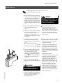
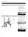
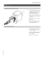
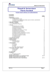
Start-up/Service
Instructions
for use by heating contractor
Vitola 200
VB2 Series
Oil-/Gas-Fired Boiler
Heating input
83 to 300 MBH
24 to 88 kW
VITOLA 200
IMPORTANT
Read and save these instructions
for future reference.
5167 405 v2.2 04/2008
Safety, Installation and Warranty Requirements
Safety, Installation and Warranty Requirements
Please ensure that this manual is read and understood before commencing installation. Failure to comply with the issues listed below
and details printed in this manual can cause product/property damage, severe personal injury, and/or loss of life. Ensure all
requirements below are understood and fulfilled (including detailed information found in manual subsections).
H Licensed professional heating
contractor
The installation, adjustment, service,
and maintenance of this equipment
must be performed by a licensed
professional heating contractor.
Please see section
entitled “Important
Regulatory and
Installation
Requirements.”
"
H Product documentation
Read all applicable documentation
before commencing installation. Store
documentation near boiler in a readily
accessible location for reference in
the future by service personnel.
H Contaminated air
Air contaminated by chemicals can
cause by-products in the combustion
process which are poisonous to
inhabitants and destructive to
Viessmann equipment.
For a listing of
chemicals which cannot
be stored in or near the
boiler room, please see
section entitled
“Combustion Air Supply”
in Installation Instructions.
"
H Carbon monoxide
Improper installation, adjustment,
service and/or maintenance can cause
flue products to flow into living space.
Flue products contain poisonous
carbon monoxide gas.
H Fresh air
This equipment requires fresh air for
safe operation and must be installed
ensuring provisions for adequate
combustion and ventilation air exist.
For information
pertaining to the fresh
air requirements of this
product, please see
section entitled
“Combustion Air Supply.”
in Installation Instructions.
"
H Equipment venting
Never operate boiler without an
installed venting system. An improper
venting system can cause carbon
monoxide poisoning.
For information
pertaining to venting
and chimney
requirements, please
see section entitled “Venting
Connection” in Installation Instructions.
All products of combustion must be
safely vented to the outdoors.
"
For a listing of
applicable literature,
please see section
entitled “Important
Regulatory and
Installation Requirements.”
"
WARNING
Installers must follow local
regulations with respect to
installation of carbon monoxide
detectors. Follow manufacturer’s
maintenance schedule of boiler.
H Warranty
Information contained in
this and related product
documentation must be
read and followed. Failure
to do so renders warranty
null and void.
5167 405 v2.2
H Advice to owner
Once the installation work is
complete, the heating contractor must
familiarize the system
operator/ultimate owner with all
equipment, as well as safety
precautions/
requirements, shut-down procedure,
and the need for professional service
annually before the heating season
begins.
For information
pertaining to the proper
installation, adjustment,
service and maintenance
of this equipment to
avoid formation of carbon monoxide,
please see sections entitled
“Combustion Air Supply” and “Venting
Connection” in Installation Instructions.
"
2
Safety, Installation and Warranty Requirements
Safety, Installation and Warranty Requirements
(continued)
Please ensure that this manual is read and understood before commencing installation. Failure to comply with the issues
listed below and details printed in this manual can cause product/property damage, severe personal injury, and/or loss of life.
Ensure all requirements below are understood and fulfilled (including detailed information found in manual subsections).
H Fiberglass wool and ceramic fiber
materials
WARNING
Inhalation of fiberglass wool and/or
ceramic fiber materials is a possible
cancer hazard. These materials can
also cause respiratory, skin and eye
irritation.
The state of California has listed the
airborne fibers of these materials as a
possible cancer hazard through
inhalation. When handling these
materials, special care must be applied.
Precautionary measures
- Avoid breathing fiberglass dust and
contact with skin and eyes.
- Use NIOSH approved dust/mist
respirator.
- Wear long-sleeved, loose fitting
clothing, gloves and eye protection.
- Wash work clothes separately from
other clothing. Rinse washer
thoroughly.
- Operations such as sawing, blowing,
tearout and spraying may generate
airborne fiber concentration requiring
additional protection.
H Hazardous materials
WARNING
Appliance materials of construction,
products of combustion and the fuel
contain alumina, silica, heavy metals,
carbon monoxide, nitrogen oxides,
aldehydes and/or other toxic or
harmful substances which can cause
serious injury or loss of life and which
are known to the State of California
to cause cancer, birth defects and
other reproductive harm. Always use
proper safety clothing, respirators and
equipment when servicing or working
nearby the appliance.
First aid measures
- If eye contact occurs, flush eyes with
water to remove dust. If symptoms
persist, seek medical attention.
- If skin contact occurs, wash affected
areas gently with soap and warm
water after handling.
5167 405 v2.2
Suppliers of ceramic fiber products
recommend the following first aid
measures:
- Respiratory tract (nose and throat)
irritation
If respiratory tract irritation develops,
move the person to a dust free
location.
- Eye irritation
If eyes become irritated, flush
immediately with large amounts of
lukewarm water for at least 15
minutes. Eyelids should be held away
from the eyeball to ensure thorough
rinsing. Do not rub eyes.
- Skin irritation
If skin becomes irritated, remove
soiled clothing. Do not rub or scratch
exposed skin. Wash area of contact
thoroughly with soap and water.
Using a skin cream or lotion after
washing may be helpful.
- Gastrointestinal irritation
If gastrointestinal tract irritation
develops, move the person to a dust
free environment.
Suppliers of fiberglass wool products
recommend the following precautions
be taken when handling these materials:
3
Contents
Page
Safety
Important Regulatory and Installation Requirements
General Information
About these Service Instructions
....
5
........................................
6
.......................................................................
6
...........................................................................
7
........................................................................................
8
Necessary Tools
Start-up
and Service
Additional Information
Initial Start-up
Service
Parts List
....................................................................................
...............................................................
16
5167 405 v2.2
Maintenance Record
13
4
Safety
Important Regulatory and Installation Requirements
Instructing the system user
The installer of the system is
responsible to ensure the system
operator/ultimate owner is made
familiar with the system functioning, its
activation, its shut-down, and the need
for periodic service.
Initial start-up
Initial start-up must be performed by a
qualified heating contractor; values and
calibrations specified in the burner test
sheet are to be verified at this time.
Completion of the Maintenance Record
by the heating contractor is also
required.
The following topics must be covered:
Proper system operation sequence.
Explain the equipment as well as the
need for combustion air.
Demonstrate an emergency
shut-down, what to do and what not.
Explain that there is no substitute for
proper maintenance to help ensure
safe operation.
Working on the equipment
The installation, adjustment, service,
and maintenance of this boiler must be
done by a licensed professional heating
contractor who is qualified and
experienced in the installation, service,
and maintenance of hot water boilers.
There are no user serviceable parts on
the boiler, burner, or control.
Ensure main power supply to
equipment, the heating system, and all
external controls has been deactivated.
Close main oil or gas supply valve. Take
precautions in both instances to avoid
accidental activation of power during
service work.
Please carefully read this manual prior
to attempting start-up, maintenance
or service. Any warranty is null and
void if these instructions are not
followed.
For information regarding other
Viessmann System Technology
componentry, please reference
documentation of the respective
product.
We offer frequent installation and
service seminars to familiarize our
partners with our products. Please
inquire.
Leave all literature at the installation
site and advise the system
operator/ultimate owner where the
literature can be found. Contact
Viessmann for additional copies.
5167 405 v2.2
Technical literature
Literature applicable to all aspects of
the Vitola:
- Technical Data Manual
- Installation Instructions
- Start-up/Service Instructions
- Installation codes mentioned
in this manual
5
General Information
About these Service Instructions
Take note of all symbols and notations intended to draw attention to potential hazards or important product information.
These include ”WARNING”, ”CAUTION”, and ”IMPORTANT”. See below.
WARNING
Indicates an imminently hazardous
situation which, if not avoided, could
result in death, serious injury or
substantial product/property damage.
CAUTION
Indicates an imminently hazardous
situation which, if not avoided, may
result in minor injury or
product/property damage.
IMPORTANT
Warnings draw your attention to the
presence of potential hazards or
important product information.
Cautions draw your attention to the
presence of potential hazards or
important product information.
Helpful hints for installation, operation
or maintenance which pertain to the
product.
This symbol indicates that additional,
pertinent information is to be found in
column three.
This symbol indicates that other
instructions must be referenced.
Necessary Tools
Special Items
Approved leak detection fluid
Testing/analysis equipment
Flue gas analyzer
Use only calibrated equipment.
Cleaning supplies
Hand brush
Rags
Vacuum cleaner
Cleaning brush (Standard equipment)
Technical information
Operating Instructions of boiler and all
accessories
Parts List of each accessory
6
5167 405 v2.2
Parts
Rope sealant for combustion chamber
door
Refractory for combustion chamber
door
Burner refractory for combustion
chamber
Start-up and Service
Initial Start-up
See Operating Instructions, Service Instructions of
Power Burner and Boiler Control
1. Ensure combustion and ventilation air
openings of boiler room are open and
that chimney and all flue pipes are
connected, sealed and unobstructed
inside. Verify that all requirements in
the Combustion Air Supply section of
the boiler Installation Instructions are
met.
2. Ensure proper operation of expansion
tank (see Maintenance/Service
manual).
3. Ensure that system piping is flushed
out to remove debris and/or sludge.
Failure to do so could cause
settlement in the boiler causing
overheating and damage not covered
by warranty.
4. Fill heating system with water and
bleed out air completely. Ensure
complete system is properly vented
of air.
Max. system operating press.
. . . . . . . . . . . . . . . . . . . . . . . . . . . . . . . . . . . . . . . . . . . . . . . . . . . . <30 psig
Pressure relief discharge press.
. . . . . . . . . . . . . . . . . . . . . . . . . . . . . . . . . . . . . . . . . . . . . . . . . . . . . . . . 30 psig
5. Perform a pressure test of the boiler
and the water piping. Pressure test
must not exceed 1½ times the
maximum system operating pressure
(45 psig
) of the boiler. Pressure
relief valve must be removed during
pressure test. Any leaks must be
corrected.
6. Ensure fuel proper/adequate fuel
supply exists; open oil or gas shut-off
valve.
WARNING
5167 405 v2.2
DO NOT USE GASOLINE
CRANKCASE DRAININGS OR ANY
OIL CONTAINING GASOLINE.
WARNING
Keep boiler clear and free from
combustible materials, gasoline, and
other flammable vapors and liquids.
Do not obstruct the flow of
combustion and ventilation air.
If the nitrogen pressure of the
precharged expansion tank is less
than the static pressure of the
system, inflate membrane pressure to
slightly exceed pressure of system.
The static pressure required at the
tank is based upon the static height
of the system.
Water treatment should be considered
in areas where it is known that boiler
feed water contains a high mineral
content and hardness.
In areas where freezing might occur,
an antifreeze may be added to the
system water to protect the system.
Please adhere to the specifications
given by the antifreeze manufacturer.
Do not use automotive silicate-based
antifreeze.
Please observe that an
antifreeze/water mixture may require
a backflow preventer within the
automatic water feed and influence
components such as diaphragm
expansion tanks, radiation, etc. A
40% antifreeze content will provide
freeze-up protection to -10°F / -23°C.
Do not use antifreeze other than
specifically made for hot water
heating systems. System also may
contain components which might be
negatively affected by antifreeze.
Check total system frequently when
filled with antifreeze.
7. Verify completeness of all discussion
points on the following pages in the
section entitled Service before
starting up system.
7
Start-up and Service
Service
1. Shut down heating system
1. Ensure main power supply to
equipment, the heating system, and
all external controls has been
deactivated. Take precautions in both
instances to avoid accidental
activation.
2. Close main gas or oil supply valve
near burner (and near oil tank if
applicable).
WARNING
Always keep the manual fuel supply
valve shut off if the burner is shut
down for an extended period of time.
2. Open combustion chamber door
Illustration shows Viessmann Chassis
Burner installed on Vitola 200 boiler.
1. Disconnect and remove burner hood
(Viessmann Chassis burner only).
2. Disconnect
from burner.
plug-in connector
IMPORTANT
Disconnect gas supply piping if a gas
burner is installed.
Remove oil lines if an oil burner is
installed.
3. Remove four bolts of combustion
chamber door
and open (hinge pin
must remain inserted).
WARNING
5167 405 v2.2
Never burn garbage or paper in the
unit, and never leave combustible
material around it.
8
Start-up and Service
Service
(continued)
3. Clean chimney, flue pipe and heat exchanger
1. Check flue pipe condition, chimney
connection, and chimney itself, both
inside and outside, for rust,
deterioration, blockage, or leakage.
Repair or replace as necessary.
2. Ensure combustion and ventilation air
openings of boiler room are open and
unobstructed.
3. Remove combustion chamber insert
and clean.
4. Clean heat exchanger surfaces with
the cleaning brush
and using a
vacuum cleaner.
4. Check all gaskets and insulation
1. Check all gaskets and the sealant
rope of the combustion chamber door
for wear or damage.
2. Check the combustion chamber door
refractory and burner refractory for
wear or damage.
5167 405 v2.2
3. Replace worn or damaged parts.
9
Start-up and Service
Service
(continued)
5. Close combustion chamber door
1. Push in combustion chamber insert
as far as it will go. Handle
must be at bottom.
IMPORTANT
The combustion chamber insert has a
lip at the back. Push combustion
chamber insert into combustion
chamber so that lip slides into matching
notch at the back of the combustion
chamber. Failure to do so will damage
door refractory when door is closed.
2. Close combustion chamber door
and tighten four bolts in a cross-wise
fashion.
3. Reconnect burner fuel line(s).
4. Mount burner hood (if applicable).
WARNING
Reconnect oil burner and follow
instructions found in burner
installation/start-up manual.
WARNING
For gas burner, perform necessary
leak detection tests.
6. Check heating system and domestic hot water connections
Ensure all connections are pressure
tight.
7. Ensure proper operation of all safety devices
Flush float type low water cut-offs (if
used).
If oil-lubricated pumps are used, ensure
proper lubrication.
10
If motorized zone valves are used,
check and service as necessary.
Refer to manufacturer’s instructions for
each of the components listed above.
Follow local regulations with respect to
backflow preventers.
5167 405 v2.2
Ensure proper operation of low water
cut-off(s), pressure relief valve, and
pump(s).
Start-up and Service
Service
(continued)
8. Ensure proper operation of automatic fill valve and expansion tank; also ensure proper system water pressure
IMPORTANT
Check fill pressure when system is cold.
Ensure proper operation of automatic fill
valve and expansion tank.
If a non-diaphragm expansion tank is
used, ensure the correct water level is
present (expansion tank should be 2/3
full).
The usual water fill pressure is between
10 and 15 psi with the system cold.
Check pressure gage
on safety
header. All leaks must be corrected.
Refer to manufacturer’s instructions for
each of the components listed above.
CAUTION
This boiler is not for use in systems
where water is constantly or
frequently replenished. Minerals such
as calcium in make-up water can
deposit on heat exchanger causing
overheating, and eventually the boiler
will leak. This type of failure is not
covered by warranty. Water must not
be drained from system for use by
cleaning personnel.
9. Ensure enclosure panels are correctly fitted
1. Ensure all enclosure panels are
seated properly; adjust as necessary.
2. Ensure strain reliefs on rear panel are
tight and seated properly.
10. Ensure mixing valve(s) rotates easily and is pressure tight (if installed)
1. Remove mixing valve lever.
2. Check if mixing valve rotates easily.
3. Ensure mixing valve is pressure tight
(does not leak). Replace O-Ring seals
if necessary.
5167 405 v2.2
4. Reinstall mixing valve lever.
11
Start-up and Service
Service
(continued)
11. Ensure that an adequate combustion air supply exists in the boiler room
Ensure fresh air intake of boiler room is
open. This opening must never be
blocked or partially covered.
12. Ensure functionality of the barometric draft regulator of the burner
During operation of the burner, the
barometric installed in the vent system
must move freely.
13. Calibrate the burner
Service Instructions
Burner
WARNING
DO NOT START THE BURNER
UNLESS THE COMBUSTION
CHAMBER DOOR IS SECURED IN
PLACE.
CAUTION
When the boiler is fired for the first
time, the ceramic fiber insulation on
the back of the combustion chamber
door will require ½ to 1 hour to firing
time to “cure.” An odor may occur
during this time. Final measurements
of CO must be done only after the
“cure” is complete.
WARNING
DO NOT ATTEMPT TO START THE
BURNER WHEN EXCESS OIL HAS
ACCUMULATED IN THE
COMBUSTION CHAMBER, WHEN
THE UNIT IS FULL OF VAPOR, OR
WHEN THE COMBUSTION CHAMBER
IS VERY HOT.
WARNING
DO NOT USE GASOLINE
CRANKCASE DRAININGS OR ANY
OIL CONTAINING GASOLINE.
14. For systems subject to freezing temperatures
12
5167 405 v2.2
CAUTION
If the system is subject to freezing
temperatures and is not filled with
antifreeze for protection, the system
including the boiler must be drained
of water. The valve before automatic
feed valve (if installed) must be
closed; all other valves, air vents, and
drain valves must stay open.
Additional Information
Parts List
Ordering Replacement Parts:
Please provide boiler Model and Serial
Number from rating plate when ordering
replacement parts. Order replacement
components from your Viessmann
distributor.
008 Pressure vessel insulation blanket
009 2-Channel strain relief
010 8-Channel strain relief
011 Cover
015 Mounting bracket, rear
016 Mounting bracket, front
017 Edgemolding cover
Boiler control, see
separate Parts List
Rating plate
5167 405 v2.2
Parts
001 Insulation jacket (entire insulation
assembly)
002 Top panel
003 Front panel
004 Rear panel
005 Side panels right and left
006 Rear insulation blanket
007 Front insulation blanket
13
Additional Information
Parts List
(continued)
Parts List
012 Combustion chamber door
013 Packing seal
014 Combustion chamber door
refractory
032 Observation port cover
033 Rope seal
034 Door pin
018 Combustion chamber refractory
019 Flue gas collector
(order 027 Sealant)
020 Combustion chamber insert
021 Boiler shell
025 Cleaning brush handle
036 Cleaning brush head
Not illustrated
026 Insulation accessories
027 Flue outlet sealant
028 Spray paint, vitosilver
029 Touch-up pen, vitosilver
030 Installation Instructions
031 Start-up/Service Instructions
034
021
033
5167 405 v2.2
032
14
Additional Information
5167 405 v2.2
Notes
15
Additional Information
Start-up
Maintenance/Service
Maintenance/Service
Maintenance/Service
Maintenance/Service
Maintenance/Service
Maintenance/Service
Maintenance/Service
Maintenance/Service
Maintenance/Service
on:
by:
on:
by:
Before each heating season begins,
have the following service and
maintenance done by a licensed,
professional heating contractor:
Printed on environmentally friendly
(recycled and recyclable) paper.
Maintenance Record
WARNING
Neglecting to perform necessary
maintenance can cause unsafe
operation.
1. Boiler heat exchanger inspected and
cleaned.
Operating Instructions
To operate boiler, please follow all instructions located in the
Operating Instructions and User’s Information Manual of
the Power Burner and the Boiler Control
Viessmann Manufacturing Company (U.S.) Inc.
45 Access Road
Warwick, Rhode Island • 02886 • USA
Tel. (401) 732-0667 • Fax (401) 732-0590
www.viessmann-us.com • [email protected]
16
Viessmann Manufacturing Company Inc.
750 McMurray Road
Waterloo, Ontario • N2V 2G5 • Canada
Tel. (519) 885-6300 • Fax (519) 885-0887
www.viessmann.ca • [email protected]
5167 405 v2.2
3. Burner checked, and if necessary,
adjusted for proper combustion and
operation. Check for adequate supply
of fresh outside combustion and
ventilation air.
Technical information subject to change without notice.
2. Vent system inspected for
deterioration, leaks, corrosion, proper
draft, and proper operation. Check
vent system for compliance with
local and national code requirements.
Repair or replace as required.