1
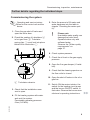
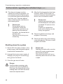
Service instructions
VIESMANN
for contractors
Vitoplex 200
Type SX2A, 700 to 1950 kW
Oil/gas boiler
For applicability, see the last page
VITOPLEX 200
5692 849 GB
10/2013
Please keep safe.
Safety instructions
Safety instructions
Please follow these safety instructions closely to prevent accidents and material losses.
Safety instructions explained
Note
Details identified by the word "Note" contain additional information.
■ The Code of Practice of relevant trade
associations
■ All current safety regulations as
defined by DIN, EN, DVGW, TRGI,
TRF, VDE and all locally applicable
standards,
Gas Safety (Installation & Use) Regulations the appropriate Building Regulationeither the Building regulations,
theBuilding Regulation (Scotland),
Building Regulations (Northern Ireland), the Water Fittings Regulation or
Water Bylaws in Scotland, the current
I.E.E. Wiring Regulations.
Target group
If you smell gas
Danger
This symbol warns against the
risk of injury.
!
Please note
This symbol warns against the
risk of material losses and environmental pollution.
These instructions are exclusively intended for qualified contractors.
■ Work on gas installations must only be
carried out by a registered gas fitter.
■ Work on electrical equipment must
only be carried out by a qualified electrician.
■ The system must be commissioned by
the system installer or a qualified person authorised by the installer.
Regulations
5692 849 GB
Observe the following when working on
this system:
■ Statutory regulations regarding the
prevention of accidents
■ Statutory regulations regarding environmental protection
Danger
Escaping gas can lead to explosions which may result in serious
injury.
■ Do not smoke. Prevent naked
flames and sparks. Do not
switch lights or electrical appliances on or off.
■ Close the gas shut-off valve.
■ Open windows and doors.
■ Evacuate any people from the
danger zone.
■ Notify your gas or electricity
supplier and your local heating
contractor from outside the
building.
■ Shut off the electricity supply to
the building from a safe place
(outside the building).
2
Safety instructions
Safety instructions (cont.)
If you smell flue gas
Danger
The simultaneous operation of
the boiler and appliances that
extract air to the outside can
result in life threatening poisoning due to reverse flow of the flue
gas.
Fit an interlock circuit or take suitable steps to ensure a sufficient
supply of combustion air.
Danger
Flue gas can lead to life threatening poisoning.
■ Shut down the heating system.
■ Ventilate the installation site.
■ Close all doors in the living
space.
Flue systems and combustion air
Working on the system
Ensure that flue systems are clear and
cannot be sealed, for instance due to
accumulation of condensate or other
causes. Ensure a sufficient supply of
combustion air.
Instruct system users that subsequent
modifications to the building characteristics are not permissible (e.g. cable/pipework routing, cladding or partitions).
Danger
Leaking or blocked flue systems,
or an insufficient supply of combustion air can cause life threatening poisoning from carbon
monoxide in the flue gas.
Ensure the flue system is in
proper working order. Apertures
for supplying combustion air
must be non-closable.
5692 849 GB
Extractors
Operating appliances that extract air to
the outside (cooker hoods, extractors, air
conditioning units, etc.) can create negative pressure. If the boiler is operated at
the same time, this can lead to reverse
flow of the flue gas.
■ Where gas is used as the fuel, close
the main gas shut-off valve and safeguard it against unintentional reopening.
■ Isolate the system from the power supply (e.g. by removing the separate fuse
or by means of a mains isolator) and
check that it is no longer 'live'.
■ Safeguard the system against reconnection.
Danger
Hot surfaces can cause burns.
■ Before maintenance or service
work, switch OFF the appliance and let it cool down.
■ Never touch hot surfaces on
the boiler, burner, flue system
or pipework.
!
Please note
Electronic assemblies can be
damaged by electrostatic discharge.
Before beginning work, touch
earthed objects, such as heating
or water pipes, to discharge static
loads.
3
Safety instructions
Safety instructions (cont.)
Repair work
!
Please note
Repairing components that fulfil a
safety function can compromise
the safe operation of the system.
Faulty components must be
replaced with original Viessmann
spare parts.
Auxiliary components, spare and
wearing parts
Please note
Spare and wearing parts that
have not been tested together
with the system can compromise
its function. Installing non-authorised components and making
non-approved modifications or
conversions can compromise
safety and may invalidate the
warranty.
For replacements, use only original spare parts supplied or
approved by Viessmann.
5692 849 GB
!
4
Index
Index
Product information
Intended use.........................................................................................................
6
Commissioning, inspection, maintenance
Steps - commissioning, inspection and maintenance..........................................
Further details regarding the individual steps.......................................................
7
9
Parts lists
Parts list................................................................................................................ 20
Water quality
Water quality requirements.................................................................................. 27
Using antifreeze in boilers.................................................................................... 30
Commissioning/service reports........................................................................ 32
Specification....................................................................................................... 33
Certificates
Declaration of conformity...................................................................................... 34
Manufacturer's certificate according to the 1st BImSchV [Germany]................... 35
5692 849 GB
Keyword index.................................................................................................... 36
5
Product information
Intended use
The appliance is only intended to be
installed and operated in sealed unvented heating systems that comply with
EN 12828, with due attention paid to the
associated installation, service and
operating instructions as well as the
details in the datasheet.
It is only designed for the heating up of
heating water.
Commercial or industrial usage for a purpose other than the heating up of heating
water shall be deemed inappropriate.
Intended use presupposes that a fixed
installation in conjunction with permissible components designed for this purpose has been carried out.
Every other use will be deemed to be
inappropriate. Any resulting losses are
excluded from the manufacturer's liability.
Any usage beyond this must be
approved by the manufacturer for the
individual case.
5692 849 GB
Intended use also includes the adherence to maintenance and inspection
intervals.
6
Commissioning, inspection, maintenance
Steps - commissioning, inspection and maintenance
For further information regarding the individual steps, see the page indicated
Commissioning steps
Inspection steps
Maintenance steps
•
•
•
•
•
•
•
•
1. Commissioning the system...........................................
9
2. Shutting down the system............................................. 10
3. Opening the boiler door and cleaning cover............... 11
4. Cleaning the turbulators, heating surface, flue outlet
and flue pipe.................................................................... 12
•
•
•
5. Checking all gaskets and packing cords on the flue
gas side
•
•
•
6. Checking the thermal insulation components on the
boiler door
•
7. Inserting turbulators, securing the boiler door and
cleaning cover................................................................. 13
•
•
•
8. Checking connections and sensor well on the heating
water side for tightness
•
•
•
•
•
•
•
•
•
9. Checking the function of the safety equipment........... 14
•
•
•
•
•
•
•
•
12. Checking the thermal insulation
•
•
•
17. Checking the installation room ventilation
•
•
•
5692 849 GB
Page
•
•
•
•
•
•
10. Checking the expansion vessel and system pressure 14
11. Checking the firm seating of electrical plug-in
connections and cable grommets
13. Checking the water quality............................................ 15
14. Cleaning the sight glass in the boiler door.................. 17
15. Checking the mixer for ease of operation and leaks... 17
16. Checking the function of the return temperature
raising facility (if installed)
18. Checking the flue pipe for tightness
19. Adjusting the burner...................................................... 17
20. Instructing the system user........................................... 18
7
Commissioning, inspection, maintenance
Steps - commissioning, inspection and… (cont.)
Commissioning steps
Inspection steps
Maintenance steps
21. Operating and service documents................................ 19
5692 849 GB
•
Page
8
Commissioning, inspection, maintenance
Further details regarding the individual steps
Commissioning the system
Operating and service instructions for the control unit and the
burner
01. Close the gas shut-off valve and
open the boiler door.
02. Check the seating of turbulators C
in hot gas flues B. Turbulator
spring clips D must lock into place
behind first constriction E.
05. Enter the amount of fill water and
water hardness into the table in
chapter "Checking the water quality".
!
Please note
Unsuitable water quality can
damage the boiler shell.
Operate boilers only with
softened water.
Observe the "Water quality
requirements" on
page 27.
06. Check system pressure.
07. Check the oil level or the gas supply
pressure.
08. Open the flue gas damper (if installed).
09. Check that the cleaning aperture on
the flue outlet is closed.
10. Open the shut-off valves in the oil or
gas line.
A Turbulator extractor
03. Check that the installation room
vent is open.
11. Switch ON the mains isolator, the
switch for the heating circuit pump
and the burner ON/OFF switch, in
that order. Observe the burner manufacturer’s operating instructions.
5692 849 GB
04. Fill the heating system with water
and vent the system.
Permissible operating pressure:
6 bar (0.6 MPa)
9
Commissioning, inspection, maintenance
Further details regarding the individual steps (cont.)
12. The dew point range must be
cleared as quickly as possible. For
this reason prevent all heat supply
to consumers when heating the system from cold. This also applies
when restarting after maintenance
and cleaning work.
!
Please note
During boiler heat-up,
unpleasant fumes and
odours can result from outgassing from the thermal
insulation, the thermal block
and the paint.
Vent the room during commissioning.
13. After the flow temperature has been
reached, switch ON the heat consumers in sequence and change the
burner over to automatic mode.
!
Please note
Internal gas emissions from
the thermal block can lead to
increased CO values in the
flue gas.
Continue to operate the
boiler until a decline can be
clearly recognised.
14. Check all gaskets and plugs, and
retighten if necessary.
15. Check the boiler door and cleaning
cover after approx. 50 hours run and
retighten all screws.
Shutting down the system
1. Switch OFF the mains isolator or the
power supply, and safeguard against
unauthorised reconnection.
2. Interrupt the burner power supply. If
installed, pull plug-in connectors fA
and lÖ from the burner.
!
Please note
Draining the boiler with a suction
pump will create negative pressure inside the boiler.
Only drain the boiler with a suction pump when the air vent valve
is open.
3. Close the gas shut-off valve.
5692 849 GB
Danger
Heating water escaping under
pressure will injure bystanders.
Only open the connections on the
heating water side after the boiler
has been depressurised.
10
Commissioning, inspection, maintenance
Further details regarding the individual steps (cont.)
Opening the boiler door and cleaning cover
Note
On gas burners, disconnect the gas supply pipe.
5692 849 GB
4x
11
Commissioning, inspection, maintenance
Further details regarding the individual steps (cont.)
Cleaning the turbulators, heating surface, flue outlet and flue
pipe
1. Pull turbulators B out towards the
front with a quick tug. For this, use
turbulator extractor A from the
cleaning equipment.
3. Remove combustion residues from
the flue pipe and the flue outlet
through the cleaning aperture in flue
outlet E using a vacuum cleaner.
5692 849 GB
2. Clean flues C and combustion
chamber D with the brush.
Remove combustion residues with a
vacuum cleaner.
12
Commissioning, inspection, maintenance
Further details regarding the individual steps (cont.)
Inserting turbulators, securing the boiler door and cleaning
cover
Note
On gas burners, mount the gas supply
pipe.
Check all gas connections for
tightness.
Danger
Escaping gas leads to a risk of
explosion.
5692 849 GB
4x
13
Commissioning, inspection, maintenance
Further details regarding the individual steps (cont.)
1. Push turbulators C far into hot gas
flues B. Spring clip E must snap
into place behind first constriction
D.
2. Tighten screws A crosswise (torque
25 Nm).
Danger
Leaks can lead to risk of poisoning through escaping
gas.
Check gaskets carefully.
Note
This snapping into place prevents the
turbulators from slipping forward during boiler operation.
Checking the function of the safety equipment
Check safety valves, water level and
pressure limiter in accordance with manufacturer's details.
Checking the expansion vessel and system pressure
Expansion vessel manufacturer's
documentation
Note
Check when system is cold.
Expansion vessel
Note
The pre-charge pressure of the
expansion vessel (p0) is made up of
the static system pressure (pSt)
(= static head) and a supplement:
p0 = pSt + supplement.
The supplement depends on the high
limit safety cut-out setting. The following applies:
■ 100 °C: 0.2 bar (0.02 MPa)
■ 110 °C: 0.7 bar (0.07 MPa).
*1
2. If the pre-charge pressure of the
expansion vessel is lower than the
static system pressure: Top up with
nitrogen until the pre-charge pressure is 0.1 to 0.2 bar (0.01 to
0.02 MPa) higher.
The static pressure corresponds to
the static head.
3. Top up with softened water*1 until the
charge pressure of the cooled system
is 0.1 to 0.2 bar (0.01 to 0.02 MPa)
higher than the pre-charge pressure
of the expansion vessel.
Permiss. operating pressure: 6 bar
(0.6 MPa)
For water quality requirements, see page.
14
5692 849 GB
1. Drain the system until the pressure
gauge shows "0". Alternatively: Close
the cap valve on the expansion vessel and reduce the pressure in the
expansion vessel.
Commissioning, inspection, maintenance
Further details regarding the individual steps (cont.)
Pump controlled pressure maintaining systems
In heating systems with automatic pressure maintaining systems provide individual protection by installing an expansion vessel for each boiler. This applies
in particular to pump-controlled systems
with integral deaeration.
Boiler
output
Expansion vessel
kW
l
up to
1000
140
up to
2100
300
It reduces the frequency and level of
pressure fluctuations. This contributes
considerably to improved operational
reliability and longer service life of the
system components. Failure to observe
these recommendations may result in
damage to the boiler or to other system
components.
Only use pump controlled pressure
maintaining systems that are sealed
against corrosion. The pressure maintaining systems must be protected
against oxygen ingress into the heating
water. Otherwise damage to the system
through oxygen corrosion can result.
Pump controlled pressure maintaining
systems with atmospheric deaeration
through cyclical pressure release bring
about central post-ventilation of the heating system. They do not provide oxygen
removal in the sense of corrosion protection as described in VDI 2035 Part 2.
Note
Check the pressure maintaining system
in line with the manufacturer's instructions.
!
Please note
Cyclical pressure fluctuations
and more significant pressure differentials point towards a system
fault. Such faults result in damage to other heating system components.
Limit pressure fluctuations to the
lowest possible differential.
Checking the water quality
5692 849 GB
Observe the instructions in chapter
"Water quality requirements".
15
Commissioning, inspection, maintenance
Further details regarding the individual steps (cont.)
Enter the amount of top-up water and the
total hardness of the feed and boiler
water into the table.
Meter reading
Fill and top- Total water
up water
volume
m3
m3
Total hardness
Feedwater Boiler water
pH value Date
m3
The pH value should be between 9 and
10.5.
5692 849 GB
The total hardness of the feed and topup water must not exceed 0.11 °dH (total
value of alkaline earths ≤ 0.02 mol/m3).
16
Commissioning, inspection, maintenance
Further details regarding the individual steps (cont.)
Cleaning the sight glass in the boiler door
Note
Check the gaskets and hose connection
for leaks.
Checking the mixer for ease of operation and leaks
1. Remove the motorised lever from the
mixer handle.
2. Check the mixer for ease of operation.
3. Check the mixer for leaks. Replace
the O-ring gaskets if the mixer is leaking.
4. Snap the motorised lever into place.
Adjusting the burner
5692 849 GB
Adjust the maximum oil or gas throughput of the burner to the rated boiler heating output.
Rated
heating
output
kW
700
900
1100
1300
Pressure drop on the
hot gas side
Pa
270
460
400
570
mbar
2.7
4.6
4.0
5.7
17
Commissioning, inspection, maintenance
Further details regarding the individual steps (cont.)
Rated
heating
output
kW
1600
1950
Pressure drop on the
hot gas side
Pa
650
850
mbar
6.5
8.5
To protect the system against dew point
corrosion, burner stage 2 (full heating
output) must be set to the rated boiler
heating output. It must remain switched
on, also during the summer months
(burner stage 2 on constant standby).
Partial load operation
Set the minimum heating output for the
base load stage in accordance with the
flue system. The flue system must be
suitable for the low flue gas temperatures.
In the case of frequent cycling in standby
mode and for partial loads below 40 %
we recommend that you:
■ Insulate the flue gas collector
■ Install a motorised flue gas damper
■ Set the minimum runtime of the boiler
to 10 min
This extends the service life and reduces
running costs.
Operation with burner load ≥ 60 %
The minimum boiler water temperature
for oil operation is 50 °C and for gas
operation 60 °C.
Adjust the return temperature raising
facility to a minimum of 40 °C (oil operation) or 53 °C (gas operation).
To protect the boiler, the minimum heating output in the base load stage is set to
60 % of the rated heating output (see
table).
Rated heating
output
kW
700
900
1100
1300
1600
1950
Minimum heating
output to be set
(burner stage 1)
kW
420
540
660
780
960
1170
A minimum flue gas temperature is
required for the base load stage, the
value of which is subject to the design of
the flue system.
Operation with burner load ≥ 40 % and
< 60 %
The minimum system temperatures
(flow/return) are 60/50 °C for oil operation and 70/60 °C for gas operation.
Operation with burner load < 40 %
The minimum system temperatures
(flow/return) are 60/55 °C for oil operation and 70/65 °C for gas operation.
The installer should instruct the user in
the operation of the system.
18
5692 849 GB
Instructing the system user
Commissioning, inspection, maintenance
Further details regarding the individual steps (cont.)
Operating and service documents
1. Complete and detach the customer
registration card:
■ Hand the system user their section
for safekeeping.
■ Retain the heating contractor's
section.
5692 849 GB
2. File all parts lists, operating and service instructions in the folder and hand
this over to the system user.
The installation instructions are no
longer required after the appliance
has been installed. They do not need
to be retained.
19
Parts lists
Parts list
Parts
001 Boiler door
002 Studs
003 Sight glass pack, comprising pos.
004 to 007
004 Sight glass frame pack
005 Gasket
006 Hose nozzle
007 Plastic hose
008 Hose pack Ø 18 mm
009 Upper insulation block
010 Lower insulation block
011 Thermal insulation mat
012 Packing GF 25 x 15
013 Turbulator
014 Gasket, flow/return
015 Gasket, safety valve
016 Cleaning cover
017 Packing
018 Sensor well, boiler water temperature sensor
200 Cover panel, front
201 Cover panel, back
202 Front panel, top (only for 1600 and
1950 kW)
203 Front and back panel, top
204 Front panel, bottom
205 Back panel, bottom
206 Side panel
207 Side panel, control unit
208 Centre rail
209 Front r.h. rail
210 Front l.h. rail
*2
*3
211
212
213
214
215
216
217
218
219
220
221
222
223
224
225
226
227
228
307
308
Back r.h. rail
Back l.h. rail
Thermal insulation jacket
Thermal insulation jacket, centre
(only for 1100 to 1950 kW)
Thermal insulation mat, back
Thermal insulation mat, l.h. back
Thermal insulation mat, r.h. back
Mounting bracket, back
Mounting bracket
Channel retainer
Cable channel, upper section
Cable channel, lower section
Edge protector
Cover, sensor coupling
Thermal insulation mat, front
Thermal insulation mat, l.h. front
Thermal insulation mat, r.h. front
Mounting bracket, fascia
Vitoplex 200 logo
Viessmann logo
Wearing part
020 Cleaning brush
Accessories
021 Brush handle
022 Extension piece
023 Turbulator extractor
024 Burner plate pack
025 Burner plate gasket*2
229 Back panel retrofit kit*3, not shown
Parts not shown
300 Thermal insulation pack
301 Touch-up spray paint, Vitosilver
302 Touch-up paint stick, Vitosilver
303 Installation instructions
304 Service instructions
For sizes 700 and 900 kW with seal ring;
for sizes 1100 to 1950 kW with glass fibre-reinforced fabric ribbon
Suitable for pos. 216 and 217
20
5692 849 GB
Information on ordering spare parts
Quote the part and serial numbers (see
type plate) and the position number of
the required part (as per this parts list).
Standard parts are available from your
local supplier.
Parts lists
Parts list (cont.)
A Type plate, optionally left or right
B Boiler control unit (see parts list in
the service instructions of the boiler
control unit)
C Burner cable (see parts list in the
service instructions of the boiler
control unit)
5692 849 GB
305 Decorative adhesive tape
306 Flame tube gasket pack
21
Parts lists
Parts list (cont.)
For boiler sizes 700 to 1300 kW
012
001 308
009
008
011
003
025
005
004
006
007
5692 849 GB
024
010
22
Parts lists
Parts list (cont.)
For boiler sizes 1600 to 1950 kW
001
308
009
008
010
012
A
011
003
025
5692 849 GB
024
005
004
006
007
23
Parts lists
Parts list (cont.)
015 018 224
014
016
002
017
014
013
022
020
C
023
C
021
Quantity
24
kW 700 900 1100 1300 1600 1950
42 42
52
52
52
64
5692 849 GB
Note on position number 013
Rated output
Parts lists
Parts list (cont.)
206
208
212
210
206
206
201
201
200
202
203
200
206
226
227
213
214
5692 849 GB
213
204
225
25
Parts lists
Parts list (cont.)
203
216
217
215
211
208
206
207
307
209
A
205
220
B
222
218
206
26
223
219 228
221
5692 849 GB
206
Water quality
Water quality requirements
Note
Observing the following requirements is necessary to safeguard your warranty
rights.
The warranty excludes damage due to corrosion and scaling.
Heating systems with rated operating temperatures up to
100 °C (VDI 2035)
Water used in heating systems must
meet the chemical levels of the Drinking
Water Ordinance [Germany]. If well
water or similar is used, it should be tested for suitability before filling the system.
Prevent excessive scale build-up (calcium carbonate) on the heating surfaces.
For heating systems with operating temperatures up to 100 °C, the Directive
VDI 2035 sheet 1 "Prevention of damage
in water heating installations – Scale formation in domestic hot water supply
installations and water heating installations" applies [in Germany; check local
regulations] with the following standard
values. For further information, see the
annotations to Directive VDI 2035.
> 50 to > 200 to
≤ 200
≤ 600
≤ 2.0
≤ 1.5
≤ 11.2
≤ 8.4
>
600
<
0.02
<
0.11
Soften the fill and top-up water in heating
systems operating under the following
conditions:
■ The total of alkaline earths in the fill
and top-up water exceeds the standard value.
■ Higher fill and top-up water volumes
are expected.
■ The specific system volume is greater
than 20 l/kW heating output. In multi
boiler systems, apply the output of the
smallest boiler.
5692 849 GB
Total heating
output in kW
Total alkaline
earths in
mol/m3
Total hardness in °dH
The standard values assume the following:
■ The total volume of fill and top-up
water will not exceed three times the
water content of the heating system
during its service life.
■ The specific system volume is less
than 20 l/kW heating output. In multi
boiler systems, apply the output of the
smallest boiler.
■ All measures to prevent corrosion on
the water side in accordance with
VDI 2035 sheet 2 have been implemented.
27
Water quality
Water quality requirements (cont.)
When engineering the system, observe
the following:
■ Install shut-off valves in the different
sections. This prevents the need for
draining all the heating water in the
case of repairs or system expansion.
■ Install a water meter to record the
amount of the fill and top-up water.
Enter the volume of fill water and the
water hardness into the boiler service
instructions.
■ For systems with a specific system volume in excess of 20 l/kW output (for
multi boiler systems, apply the output
of the smallest boiler), apply the
requirements of the next highest category of total output (in accordance with
the table). In the case of severe
excess (> 50 l/kW), soften the water
down to a total of alkaline earths of
≤ 0.02 mol/m3.
Operating information:
■ Commission the system step by step,
starting with the lowest boiler output
and a high heating water flow rate.
This prevents a localised concentration of limescale deposits on the boiler
heating surfaces.
■ In multi boiler systems, start all boilers
simultaneously to prevent the entire
limescale deposit settling in the heat
transfer area of just one boiler.
■ During expansion or repair work, only
drain the necessary sections.
■ Where water treatment is required,
treat even the first fill of the heating
system prior to commissioning. This
also applies to any subsequent filling,
e.g. after repairs or after system
expansion, and for all amounts of topup water.
■ Check, clean and activate filters, dirt
traps and other blow-down or separating facilities in the heating water circuit
more frequently after commissioning
or new installations; later on do so subject to requirements in line with the
water treatment applied (e.g. water
softening).
The build-up of limescale deposits on the
heating surfaces will be minimised if
these instructions are observed.
If limescale deposits have formed
because of a failure to observe the
requirements of directive VDI 2035 the
service life of the installed heating appliances will in most cases already have
been reduced. Removing the limescale
deposits is one option for restoring
operational viability. This must be carried
out by Viessmann Industrieservice or a
specialist company. Inspect the heating
system for possible damage prior to
returning it into use. It is essential that
the faulty operating parameters are corrected to prevent renewed formation of
excessive scale deposits.
The corrosion resistance of ferrous
materials on the heating water side of
heating systems and boilers depends on
the absence of oxygen in the heating
water.
28
The oxygen introduced into the heating
system with the first fill and the top-up
water reacts with the system materials
without causing damage.
5692 849 GB
Prevention of damage through corrosion on the water side
Water quality
Water quality requirements (cont.)
The characteristic blackening of the
water after some time in use indicates
that free oxygen is no longer present.
The technical rules and in particular VDI
Directive 2035-2 therefore recommend
that heating systems are designed and
operated so that a constant ingress of
oxygen into the heating water is prevented.
Opportunities for oxygen ingress during
the operation:
■ Through overflowing open expansion
vessels
■ Through negative pressure in the system
■ Through gas-permeable components
5692 849 GB
Sealed unvented systems, e.g. with a
diaphragm expansion vessel, offer good
protection against the ingress of airborne
oxygen into the system, if correctly sized
and operating at the correct pressure.
At every part of the heating system, even
at the suction side of the pump and under
all operating conditions, the system
pressure should be above ambient
atmospheric pressure.
The pre-charge pressure of the diaphragm expansion vessel should be
checked at least during the annual service.
The use of permeable components, e.g.
plastic pipes that are permeable to gas
in underfloor heating systems, should be
avoided. Provide system separation if
such components are nevertheless
used. This must separate the water flowing through the plastic pipes from other
heating circuits, e.g. from the heat
source, by the provision of a heat
exchanger made of corrosion-resistant
material.
No further anti-corrosion measures are
required for sealed hot water heating
systems subject to the above points
being observed.
However, take additional precautions
where there is a risk of oxygen ingress,
for example by adding oxygen binder
sodium sulphite (5 - 10 mg/litre into the
excess). The heating water should have
a pH value between 9.0 and 10.5.
Different conditions apply to systems
that contain aluminium components.
Where chemicals are used as part of the
corrosion protection, we recommend
that the manufacturer of the chemicals
issues a certificate of suitability of the
additives with regard to the boiler materials and the materials of the other heating equipment components.
We recommend you refer questions of
water treatment to Viessmann industrial
services or an appropriate specialist.
Further details can be found in VDI
Directive 2035-2 and EN 14868.
29
Water quality
Using antifreeze in boilers
When doing so, observe the following:
■ In general, follow the specifications
given by the antifreeze manufacturer.
■ The properties of antifreeze and water
are very different.
■ The temperature stability of the antifreeze must be sufficient for the particular application.
■ Check the compatibility with sealing
materials. If other sealing materials
are used, take this into account when
designing the system.
■ Antifreeze developed especially for
heating systems contains inhibitors
and buffer substances for corrosion
protection as well as glycol. When
using antifreeze, always observe the
manufacturer's instructions regarding
minimum and maximum concentrations.
■ The concentration must never fall
below the prescribed minimum level,
subject to the required frost protection
temperature. Check and adjust the pH
value and frost protection (measure
the density) regularly, at least once a
year, according to the manufacturer's
instructions.
■ Check with the relevant supplier
whether antifreeze may affect system
components that are not part of the
boiler, such as pumps, electrically and
pneumatically driven valves, other
types of valves, gaskets, etc.
■ If the system is filled with antifreeze, it
must be marked accordingly.
30
■ If a boiler system is changed to operate without antifreeze, flush the system in order to remove all traces of the
antifreeze.
■ The quality of the boiler water and
feedwater must meet the requirements of Directive VDI 2035.
■ The systems must be designed as
sealed unvented systems, as the antifreeze inhibitors decrease rapidly if airborne oxygen is allowed to enter.
■ Diaphragm expansion vessels must
comply with DIN 4807 [or local regulations].
■ Solder connections should preferably
be made with Ag or Cu hard solder. If
liquids containing chlorides are used
for soft soldering, any deposits must
be removed from the circuit afterwards
through thorough flushing. A higher
chloride content in the heat transfer
medium can cause corrosion damage.
■ Only use oxygen diffusion-resistant
hoses or metal hoses for flexible connections.
■ Never equip the system on the primary
side with zinc-plated heat exchangers,
containers or pipes as zinc can be corroded by glycol/water mixtures.
■ To avoid the risk of corrosion, ensure
that there is no difference in electrical
potential between system components that are in contact with antifreeze.
■ Route all pipes in such a way that circulation cannot be interrupted by gas
cushions or deposits.
■ The water circuit must always be filled
up to the highest point with the heat
transfer medium.
5692 849 GB
Viessmann boilers are designed and
built for water as a heat transfer medium.
To protect boiler systems from frost, it
may be necessary to treat the boiler
water or circulating water with antifreeze.
Water quality
Using antifreeze in boilers (cont.)
5692 849 GB
■ After filling, ensure there are no more
air cushions in the system. When the
temperature falls, gas cushions form
negative pressure and this can draw
air into the system.
■ After initial filling and commissioning,
but after 14 days at the latest, clean
the integral dirt trap so the heat transfer medium can flow freely.
■ Following any losses through leaks or
drawing off, top up the antifreeze solution according to the concentration
already in place. Establish the volume
of antifreeze as a check.
31
Commissioning/service reports
Commissioning/service reports
Commissioning
Service
Service
Service
Service
Service
Service
Service
Service
Service
Service
Service
Service
Service
Service
date:
by:
date:
by:
date:
by:
date:
by:
date:
5692 849 GB
by:
32
Specification
Specification
5692 849 GB
Rated heating output
Flue gas parameters*4
Temperature at boiler water
temperature 60 °C
– at rated heating output
– at partial load (60 %)
Temperature at boiler water
temperature 80 °C
Product ID
Efficiency η at
■ 100 % of the rated heating
output (80/60 °C)
■ 30 % of the rated heating output (65/55 °C)
*4
kW
700
900 1100 1300 1600 1950
°C
°C
°C
180
125
195
CE-0085BQ0020
% 92.2
92.2
92.2
92.3
92.2
92.3
% 96.4
96.5
96.6
96.6
96.5
96.6
Values for sizing the flue system to EN 13384 relative to 13 % CO2 for fuel oil EL
and 10 % CO2 for natural gas.
33
Certificates
Declaration of conformity
We, Viessmann Werke GmbH&Co KG, D-35107 Allendorf, declare as sole responsible body, that the following product complies with the standards specified:
Vitoplex 200, type SX2A, 700 to 1950 kW
with the Vitotronic boiler control unit
EN 267
EN 303
EN 676
EN 14394
EN 50090-2-2
EN 55014-1
EN 55014-2
EN 60335-1
EN 60335-2-102
EN 61000-3-2
EN 61000-3-3
EN 62233
TRD 702
In accordance with the following Directives, this product is designated with
_-0085:
2004/108/EC
2006/42/EC
2006/95/EC
2009/142/EC
This boiler meets the requirements of all current TRD regulations.
Allendorf, 22 February 2013
Viessmann Werke GmbH&Co KG
5692 849 GB
Authorised signatory Manfred Sommer
34
Certificates
Manufacturer's certificate according to the 1st BImSchV [Germany]
We, Viessmann Werke GmbH&Co KG, D-35107 Allendorf, confirm that the product
Vitoplex 200, type SX2A, 700 to 1950 kW complies with the following conditions
stipulated by the 1st German Immissions Order (BImSchV):
■ NOx limits in accordance with paragraph 6 (1).
■ Flue gas loss of max. 9 % in accordance with paragraph 10 (1).
■ Standard seasonal efficiency [to DIN] of at least 94 % in accordance with
paragraph 6 (2).
Allendorf, 22 February 2013
Viessmann Werke GmbH&Co KG
5692 849 GB
Authorised signatory Manfred Sommer
35
Keyword index
Keyword index
A
Adjusting the burner...........................17
Anti-corrosion measures....................29
B
Boiler door
– Opening..........................................11
– Securing.........................................13
Boiler water total hardness................16
C
Checking the expansion vessel.........14
Checking the function of the safety
equipment..........................................14
Checking the system pressure...........14
Checking the water quality.................15
Chemicals for corrosion protection....29
Cleaning cover
– Opening..........................................11
– Securing.........................................13
Cleaning the sight glass in the boiler
door....................................................17
Corrosion...........................................28
Corrosion on the water side...............28
D
Diaphragm expansion vessel.............29
E
Expansion vessel...............................29
F
Fill and top-up water..........................16
Flue outlet cleaning............................12
Flue pipe cleaning..............................12
I
Instructing the system user................18
M
Mixer check........................................17
O
Operating and service documents.....19
P
Parts lists...........................................20
Pump controlled pressure maintaining
systems..............................................15
R
Requirements for water quality..........27
S
Specification.......................................33
System
– Commissioning.................................9
– Filling with water...............................9
– Shutting down.................................10
– Venting.............................................9
T
Turbulators
– Cleaning.........................................12
– Inserting..........................................13
W
Water quality......................................27
Water treatment.................................29
5692 849 GB
H
Heating surface cleaning...................12
36
37
5692 849 GB
38
5692 849 GB
39
5692 849 GB
7438486
7438490
Viessmann Werke GmbH&Co KG
D-35107 Allendorf
Telephone: +49 6452 70-0
Fax: +49 6452 70-2780
www.viessmann.com
40
7438487
7438488
Viessmann Limited
Hortonwood 30, Telford
Shropshire, TF1 7YP, GB
Telephone: +44 1952 675000
Fax: +44 1952 675040
E-mail: [email protected]
Subject to technical modifications.
Serial No.:
7438485
7438489
5692 849 GB
Applicability