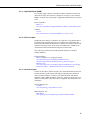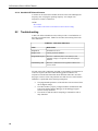
1
RF320-Series Ritron VHF/UHF Radios 10/12 C o p y r i g h t © 2 0 1 2 C a m p b e l l S c i e n t i f i c , I n c . Warranty “PRODUCTS MANUFACTURED BY CAMPBELL SCIENTIFIC, INC. are warranted by Campbell Scientific, Inc. (“Campbell”) to be free from defects in materials and workmanship under normal use and service for twelve (12) months from date of shipment unless otherwise specified in the corresponding Campbell pricelist or product manual. Products not manufactured, but that are re-sold by Campbell, are warranted only to the limits extended by the original manufacturer. Batteries, fine-wire thermocouples, desiccant, and other consumables have no warranty. Campbell’s obligation under this warranty is limited to repairing or replacing (at Campbell’s option) defective products, which shall be the sole and exclusive remedy under this warranty. The customer shall assume all costs of removing, reinstalling, and shipping defective products to Campbell. Campbell will return such products by surface carrier prepaid within the continental United States of America. To all other locations, Campbell will return such products best way CIP (Port of Entry) INCOTERM® 2010, prepaid. This warranty shall not apply to any products which have been subjected to modification, misuse, neglect, improper service, accidents of nature, or shipping damage. This warranty is in lieu of all other warranties, expressed or implied. The warranty for installation services performed by Campbell such as programming to customer specifications, electrical connections to products manufactured by Campbell, and product specific training, is part of Campbell’s product warranty. CAMPBELL EXPRESSLY DISCLAIMS AND EXCLUDES ANY IMPLIED WARRANTIES OF MERCHANTABILITY OR FITNESS FOR A PARTICULAR PURPOSE. Campbell is not liable for any special, indirect, incidental, and/or consequential damages.” Assistance Products may not be returned without prior authorization. The following contact information is for US and international customers residing in countries served by Campbell Scientific, Inc. directly. Affiliate companies handle repairs for customers within their territories. Please visit www.campbellsci.com to determine which Campbell Scientific company serves your country. To obtain a Returned Materials Authorization (RMA), contact CAMPBELL SCIENTIFIC, INC., phone (435) 227-9000. After an applications engineer determines the nature of the problem, an RMA number will be issued. Please write this number clearly on the outside of the shipping container. Campbell Scientific’s shipping address is: CAMPBELL SCIENTIFIC, INC. RMA#_____ 815 West 1800 North Logan, Utah 84321-1784 For all returns, the customer must fill out a “Statement of Product Cleanliness and Decontamination” form and comply with the requirements specified in it. The form is available from our web site at www.campbellsci.com/repair. A completed form must be either emailed to [email protected] or faxed to (435) 227-9106. Campbell Scientific is unable to process any returns until we receive this form. If the form is not received within three days of product receipt or is incomplete, the product will be returned to the customer at the customer’s expense. Campbell Scientific reserves the right to refuse service on products that were exposed to contaminants that may cause health or safety concerns for our employees. Table of Contents PDF viewers: These page numbers refer to the printed version of this document. Use the PDF reader bookmarks tab for links to specific sections. 1. Introduction .................................................................1 2. Cautionary Statements...............................................1 2.1 2.2 Licensing..............................................................................................1 RF Energy Exposure ............................................................................1 2.2.1 Compliance with RF Exposure Standards.....................................2 2.2.2 Guidelines .....................................................................................3 2.2.3 Instructions....................................................................................3 2.2.4 Antennas .......................................................................................3 2.2.5 FCC Label.....................................................................................4 3. Initial Inspection .........................................................4 4. Overview......................................................................5 5. Specifications .............................................................6 6. Installation ...................................................................8 6.1 6.2 Mounting..............................................................................................8 Interconnect..........................................................................................9 6.2.1 System Power Supply .................................................................10 6.2.2 Antenna.......................................................................................11 6.2.2.1 Antenna Bandwidth..........................................................11 6.2.2.2 Antenna Gain....................................................................11 6.3 Installation Best Practices ..................................................................12 7. Operation ...................................................................13 7.1 Link Design..........................................................................................14 7.1.1 Link Budget................................................................................15 7.1.2 Line-of-Sight ..............................................................................15 8. Troubleshooting/Maintenance.................................16 8.1 Maintenance .......................................................................................16 8.1.1 Basic Test Equipment .................................................................16 8.1.1.1 Digital Multimeter (DMM) ..............................................17 8.1.1.2 RF Power Meter ...............................................................17 8.1.1.3 Antenna Analyzer.............................................................17 8.1.1.4 Hand-Held RF Channel Scanner ......................................18 8.2 Troubleshooting .................................................................................18 i Table of Contents 8.3 Radio Functional Checks................................................................... 19 8.3.1 Input Voltage Checks ................................................................. 20 8.3.1.1 Input Voltage Range........................................................ 20 8.3.1.2 Input Voltage Load Regulation ....................................... 20 8.3.2 Radio Current Drain ................................................................... 20 8.3.3 RF Output Power Check (Dummy Load)................................... 20 8.3.4 Operating Frequency Check (RF Scanner)................................. 21 8.4 Repair ................................................................................................ 21 Appendix A. Glossary...................................................................A-1 Figures 4-1. 6-1. 6-2. RF320-Series Radio............................................................................. 5 RF320-series radio interconnect diagram............................................ 9 Radio-to-modem interface cable wiring diagram .............................. 10 2-1. 3-1. 7-1. 8-1. 8-2. Rated Power and Recommended Lateral Distance.............................. 3 RF320 Series Model Numbers to Ritron Model Number.................... 4 RF320 Series Programmed Settings .................................................. 14 LED Status Indications...................................................................... 18 Radio Troubleshooting Guide ........................................................... 19 Tables ii RF320-Series Ritron VHF/UHF Radios 1. Introduction This manual provides instructions for the installation and operation of RF320series radios within a Campbell Scientific radio telemetry network. The RF320-series radios can be interfaced with Campbell Scientific’s RF500M or RF310M radio modems at an RF base, RF remote, or RF repeater location to achieve wireless data transmissions. The RF320-series radios are inter-operable with Campbell Scientific’s RF310 series of radios operating on the same frequency. Instructions for interfacing the RF320-series radios to the RF500M or RF310M radio modems and other system components such as power sources and antenna are contained in Section 6, Installation. Information about how to design and maintain an optimal RF link is covered in Section 7, Operation, and Section 8, Troubleshooting/Maintenance. Information regarding the topology of the RF network and data flow management can be found in the RF500M instruction manual. 2. Cautionary Statements 2.1 Licensing The FCC requires the radio operator to obtain a station license for the radio before using it to transmit, but does not require an operating license or permit. The station licensee is responsible for ensuring that transmitter power, frequency and deviation are within the limits specified by the station license. The station licensee is also responsible for proper operation and maintenance of the radio equipment. This includes checking the transmitter frequency and deviation periodically, using appropriate methods. For more information, see the FCC Universal Licensing System at http://wireless.fcc.gov/uls. 2.2 RF Energy Exposure BEFORE USING YOUR RADIO, READ THIS IMPORTANT RF ENERGY AWARENESS AND CONTROL INFORMATION AND OPERATIONAL INSTRUCTIONS TO ENSURE COMPLIANCE WITH THE FCC’S RF EXPOSURE GUIDELINES. NOTICE: This radio is intended for use in occupational/controlled conditions, where users have full knowledge of their exposure and can exercise control over their exposure to meet FCC limits. This radio device is NOT authorized for general population, consumer, or any other use. This radio uses electromagnetic energy in the radio frequency (RF) spectrum to provide communications between two or more users over a distance. 1 RF320-Series Ritron VHF/UHF Radios It uses radio frequency (RF) energy or radio waves to send and receive data. RF energy is one form of electromagnetic energy. Other forms include, but are not limited to electric power, sunlight, and x-rays. RF energy, however, should not be confused with these other forms of electromagnetic energy, which when used improperly can cause biological damage. Very high levels of x-rays, for example, can damage tissues and genetic material. Experts in science, engineering, medicine, health, and industry work with organizations to develop standards for exposure to RF energy. These standards provide recommended levels of RF exposure for both workers and the general public. These recommended RF exposure levels include substantial margins of protection. All two-way radios marketed in North America are designed, manufactured, and tested to ensure they meet government established RF exposure levels. In addition, manufacturers also recommend specific operating instructions to users of two-way radios. These instructions are important because they inform users about RF energy exposure and provide simple procedures on how to control it. Please refer to the following websites for more information on what RF energy exposure is and how to control your exposure to assure compliance with established RF exposure limits. www.fcc.gov/oet/rfsafety/rf-faqs.html www.osha.gov/SLTC/radiofrequencyradiation/index.html Federal Communications Commission Regulations The FCC rules require manufacturers to comply with the FCC RF energy exposure limits for mobile two-way radios before they can be marketed in the U.S. When two-way radios are used as a consequence of employment, the FCC requires users to be fully aware of and able to control their exposure to meet occupational requirements. Exposure awareness can be facilitated by the use of a label directing users to specific user awareness information. Your Ritron two-way radio has an RF exposure product label. Also, this Campbell Scientific instruction manual includes information and operating instructions required to control your RF exposure and to satisfy compliance requirements. 2.2.1 Compliance with RF Exposure Standards Your Ritron two-way radio is designed and tested to comply with a number of national and international standards and guidelines (listed below) regarding human exposure to radio frequency electromagnetic energy. This radio complies with the IEEE and ICNIRP exposure limits for occupational/ controlled RF exposure environment at duty factors of up to 50% talk and 50% listen and is authorized by the FCC for occupational use. In terms of measuring RF energy for compliance with FCC exposure guidelines, your radio antenna radiates measurable RF energy only while it is transmitting, not when it is receiving or in standby mode. Your Ritron two-way radio complies with the following RF energy exposure standards and guidelines: • • 2 United States Federal Communication Commission, Code of Federal Regulations; 47 CFR §§ 2 sub-part J. American National Standards Institute (ANSI) / Institute of Electrical and Electronic Engineers (IEEE) C95. 1-1992. RF320-Series Ritron VHF/UHF Radios • Institute of Electrical and Electronic Engineers (IEEE) C95. 1-1999 Edition. Copyright Telecommunications Industry Association. To control exposure to yourself and others and ensure compliance with the occupational/controlled environment exposure limits, always adhere to the following procedures. 2.2.2 Guidelines • User awareness instructions should accompany device when transferred to other users. • Do not use this device if the operational requirements described herein are not met. 2.2.3 Instructions Transmit only when people in the vicinity are at least the recommended minimum lateral distance away, as shown in TABLE 2-1, from a properly installed antenna according to installation instructions. NOTE TABLE 2-1 lists the recommended minimum lateral distance for bystanders in an uncontrolled environment from transmitting antennas (i.e., monopoles over a ground plane or dipoles) at several different ranges of rated radio power for mobile radios installed on a vehicle. TABLE 2-1. Rated Power and Recommended Lateral Distance Antenna Model Rated Power of Mobile TwoWay Radio Recommended Minimum Lateral Distance from Transmitting Antenna For the DTX-145: Ram1545 (vertical whip) 7 W or less 29 cm (11.4 in) For the DTX-445: Ram1545 (vertical whip) Cushcraft PE-457-6 (6dB Yagi) 10 W or less 10 W or less 17 cm (6.7 in) 56 cm (22 in) 2.2.4 Antennas Install vertical omnidirectional antennas above a suitable ground plane taking into account the recommended minimum distance in TABLE 2-1. The antenna installation should additionally be in accordance with: The requirements of the antenna manufacturer/supplier. Instructions in the Radio Installation Manual, including minimum antenna cable lengths. 3 RF320-Series Ritron VHF/UHF Radios The installation manual should provide specific information of how to install the antennas to facilitate recommended operating distances to all potentially exposed persons. Contact Information For additional information on exposure requirements or other information, contact Ritron at (317) 846-1201 or www.ritron.com. 2.2.5 FCC Label An FCC label must be visible on the unit as installed in its final configuration. If the DTX-445 is to be installed in an enclosure, the installer must ensure that either the FCC label on the unit is visible through a door, window or other opening, or add a label to the outside of the enclosure. If a label is to be added to the outside of the enclosure, the label must be of a type which is not easily removed or damaged and contain wording: Contains FCC ID: AIERIT17445. Or in the case of DTX-145: Contains FCC ID: AIERIT17-145. 3. Initial Inspection Upon receipt of the RF320-series radio, inspect the packaging and contents for damage. File damage claims with the shipping company. Immediately check package contents against the shipping documentation. Contact Campbell Scientific about any discrepancies. Model numbers are found on each product. TABLE 3-1 correlates RF320series model numbers to Ritron DTX-145/455 transceiver model numbers. On cables, the model number is often found on the connection end of the cable. Check model information against the shipping documents to ensure the expected products and the correct length of cables were received. TABLE 3-1. RF320 Series Model Numbers to Ritron Model Number 4 RF320 Series Model Number Ritron Model Number Operating Frequencies RF320 DTX-145-OBNE 136 to 174 MHz RF321 DTX-445-GBNE 400.5 to 416.5 MHz RF322 DTX-445-HBNE 411 to 429 MHz RF323 DTX-445-OBNE 450 to 470 MHz RF320-Series Ritron VHF/UHF Radios 4. Overview FIGURE 4-1. RF320-Series Radio As offered by Campbell Scientific, RF320-series radios comprise a single board VHF/UHF FM RF transceiver module encased in an anodized, extruded aluminum enclosure with brushed aluminum end caps. Located on one end cap are two connectors and a LED view port. A female BNC bulkhead connector provides for connection to an antenna, while the transceiver module’s electrical interface is accessed via a female DB-15 connector. The dual colored LED provides a visual indicator of the transceiver’s operational status; red for transmit, green for receive, and blinking red for an error condition. A mounting bracket attached to the enclosure is suitable for mounting the radio to a Campbell Scientific mounting plate in either a vertical or horizontal position. 5 RF320-Series Ritron VHF/UHF Radios 5. Specifications RF320 RF321/322/323 DTX-145 DTX-445 AIERIT17-145 AIERIT17-445 1084A-RIT17145 1084A-RIT17445 GENERAL Ritron Module: FCC ID: Industry Canada ID: 90 FCC Rule Parts: RSS-119 Industry Canada Rule Parts: Frequency Range: RF Channels: Synthesizer Step: Channel Spacing: 6 136 to 174 MHz RF321: 400.5 to 416.5 MHz RF322: 411 to 429 MHz RF323: 450 to 470 MHz 8 Independent Tx/Rx Frequencies 2.5 kHz 6.25 kHz 12.5 kHz RF320-Series Ritron VHF/UHF Radios RF320 Frequencies Unusable: RF321/322/323 Tx and Rx Steps: 144 MHz (± 10 kHz) 158.4 MHz (± 10 kHz) 172.8 MHz (± 10 kHz) 411 to 429 MHz Band: Rx Steps: 187.1925 MHz 187.2075 MHz 201.5925 MHz 201.6075 MHz 215.9925 MHz 216.0075 MHz Rx Tx 417.60000 417.58750 418.03750 417.59375 418.04375 417.60625 418.05625 417.61250 418.06250 450 to 470 MHz Band: Rx Tx 460.80000 460.78750 461.23750 460.79375 461.24375 460.80625 461.25625 460.81250 461.26250 Frequency Stability: Tone/Code Signaling: ±2.5 PPM (-30 to +60ºC) ±1.5 PPM (-30 to +60ºC) CTCSS (Quite Call) and DCS Input Voltage: 9 to 17 Vdc Current Drain Rx Standby: 25 mA at 12.5 Vdc Transmit: 2.0 W @ 12.5 Vdc < 0.9A 5.0 W @ 12.5 Vdc < 1.2 A 2.0 W @ 12.5 Vdc < 0.9 A 5.0 W @ 12.5 Vdc < 1.2 A Dimensions / Weight: 14.5 x 7.6 x 3.5 cm (5.7 x 3 x 1.375 in) / 0.2 kg (7.3 oz) Antenna Connector: BNC female RECEIVER 12.5 kHz Narrow Band Sensitivity (12 dB SINAD) 0.25 μV Adjacent Channel: -60 dB Spurious Rejection: -65 dB -70 dB Image Rejection: -70 dB -75 dB Intermodulation: -67 dB FM hum and noise: -37 dB Conducted Spurious: -57 dB Receiver attack time (Tx to Rx): < 10 ms Noise squelch attack time: (for 20 dB quieting) < 15 ms RSSI squelch attack time: < 5 ms 7 RF320-Series Ritron VHF/UHF Radios RF320 RF321/322/323 RSSI squelch sensitivity: PC adjustable; factory set for -106 dBm Noise squelch sensitivity: PC adjustable; factory set for -121 dBm 12 – 2500 Hz @ +1 / -3 dB AUX OUT frequency response: AUX OUT level range: 0 to 3 V peak-to-peak Audio Speaker Output: > 700 mW into 8 ohms, with less than 5% THD (o to 2.5 Vrms) Audio Speaker frequency response: De-emphasized 6 dB/octave from 400 to 2500 Hz TRANSMITTER RF Power Output: Transmitter Duty Cycle: With supply below 13.5 V, 5 W Output 2.0 W @ 12.5 Vdc < 0.9 A 5.0 W @ 12.5 Vdc < 1.2 A 2.0 W @ 12.5 Vdc < 0.9 A 5.0 W @ 12.5 Vdc 50% - with case end cap maintained at 25ºC (with case end cap > 25ºC, degrades linearly to 0% at 60ºC) Voice Emissions Designator: 10K0F3E Data Emissions Designator: 9K8F1D, 11K0F2D, 11K0F3D ±2.50 kHz Deviation: Transmitter Attack Time: < 10 ms FM Hum and Noise: -40 dB Audio Distortion: < 5% Spurious and Harmonics: AUX IN Frequency Response: AUX IN Level Range: Microphone Freq Response: Microphone Level: 6. -20 dBm max -25 dBm max 8 Hz to 2500 Hz @ +1 / -3 dB 0.1 to 5 V peak-to-peak Pre-emphasized 6 dB/octave from 300 to 2500 Hz 25 mV rms for nominal ±1.5 kHz deviation Installation The RF320 radio is delivered pre-configured for operation. No user configuration or adjustments are required. Whether located at a base, repeater, or remote site, installation is a straightforward process. However, careful attention to detail and an adherence to best practices will help to improve reliability and reduce maintenance. 6.1 Mounting The mounting bracket attached to the radio is designed to align with a oneinch-on-center hole pattern and provides for ridged mounting of the radio in either a vertical or horizontal orientation. Four #6-32 x .375 inch SS Phillips head screws (CSI# 505) and four nylon grommets (CSI# 6044) are supplied for securing the radio to the backplate of a Campbell Scientific enclosure. 8 RF320-Series Ritron VHF/UHF Radios 6.2 Interconnect FIGURE 6-1 illustrates the interconnection of an RF320-series radio in a typical installation. The depicted interconnect will be the same for an installation of the radio at either an RF base, RF remote, or RF repeater location. In all cases, the radio will interface with system power, a radio modem, and an antenna. FIGURE 6-1. RF320-series radio interconnect diagram The Radio to Modem Interface Cable Assembly (CSI# 29201) provides the electrical interconnect between the DB-15 connector on the RF320 radio and the 10-pin transceiver interface connector on the RF500M or RF310M radio modem. Operational power is supplied to the radio via the red (+V) and black (-V) leads exiting the backshell of the DB-15M. The middle 10-pin connector is for connection of Campbell Scientific’s push-to-talk switch (CSI#13855), which is used to activate the radio’s transmitter for test purposes. NOTE If interfacing the RF320-series radios with an RF500M radio modem, ensure that the internal jumpers on the RF500M circuit board are configured for use with the RF310/RF320 radios (see Section 2.2.1 of the RF500M instruction manual). 9 RF320-Series Ritron VHF/UHF Radios FIGURE 6-2. Radio-to-modem interface cable wiring diagram 6.2.1 System Power Supply The RF320 radio should be connected to a DC power source of not less than 9 Vdc and not more than 17 Vdc with a capacity of 2 A. For optimal performance, it is recommended that the supply voltage be maintained between 12.5 to 14.0 Vdc. 10 NOTE Due to the amperage needed for proper operation of the RF320 during transmission, a datalogger's SW12V should not be used to power the radio. Using a datalogger's 12V to power the radio is not recommended. NOTE The radio is protected against accidental reversal of the input voltage by an internal, resettable fuse. If a reversal of input power has occurred, it will be necessary to disconnect the power supply to reset the fuse. RF320-Series Ritron VHF/UHF Radios 6.2.2 Antenna The antenna and all interconnecting cables, connectors, and adapters are critical elements of an RF link. It is essential that these components be selected to match the operational parameters of the intended system. The primary considerations when selecting an antenna are bandwidth and gain. 6.2.2.1 Antenna Bandwidth Antenna bandwidth can be defined in a number of ways. For the purposes of this document, antenna bandwidth is defined as the range of frequencies over which the antenna will transfer maximum RF energy with maximum efficiency. As with any system, the maximum transfer of energy occurs when the impedance of the load matches the impedance of the source. A properly matched radio/antenna system will radiate (and, conversely, receive) the maximum amount of RF energy. An improperly “matched” system will significantly degrade the range and performance of an RF link and, in extreme cases, could damage the radio. An indicator of how well an antenna system is matched to the radio’s 50-ohm source impedance, is the Voltage Standing Wave Ratio (VSWR). An impedance mismatch will cause a portion of the voltage waveform traveling toward the antenna to be reflected back toward the source. The interaction of the reflected waveform with the incident waveform will cause the formation of standing waves in the transmission line (antenna cable). The ratio of maximum to minimum voltage in the standing waveform is the VSWR. On some data sheets this is denoted as simply SWR. In a perfectly matched system, the VSWR is 1:1. In practice, a VSWR from 2:1 to 1.5:1 is achievable. In the latter case, 96% of the radio’s output power is being radiated, with only 4% being lost to the mismatch. NOTE The de facto industry standard impedance for RF communications equipment is 50 ohms (50 Ω), but there are commonly available coaxial cables and connectors, designed for use in video and CATV applications, that have a characteristic impedance of 75 ohms. The difference may not be visually obvious. As impedance is directly related to frequency, one should select an antenna that exhibits a minimum SWR over the operating frequencies of the radio. 6.2.2.2 Antenna Gain Antenna gain is an often misunderstood concept. The antenna is a passive element and does not generate nor add any power to the system. Simply stated, gain refers to the directivity of an antenna; its ability to direct or concentrate the RF energy in a particular direction. A hypothetical, idealized antenna is an isotropic source, radiating energy equally in all directions. One can imagine the spherical radiation pattern of an isotropic source as being represented by a beach ball. If one sits on a beach ball, the spherical shape is deformed into a toroid; the beach ball (i.e., radiation pattern) is compressed in the vertical direction and expanded, or directed, in the horizontal direction. The ratio of energy directed by an antenna in a given direction relative to the energy 11 RF320-Series Ritron VHF/UHF Radios radiated in the same direction by an isotropic antenna is defined as the antenna gain and is expressed in dBi. An isotropic antenna is a theoretical concept and doesn’t exist in nature. When actually measuring antenna gain in the laboratory, a half-wave dipole is used as the reference antenna. A half-wave dipole is known to have a directive gain of 1.64 times that of an isotropic radiator. Expressed as a ratio this equates to a gain of 2.15 dBi. Gain referenced relative to that of dipole is expressed in dBd. The relationship between dBi and dBd is: Gain in dBd = Gain in dBi – 2.15 dB. Manufacturers may use either of these designations on an antenna data sheet. It is important that one understands the relationship. When used in link budget calculations, convert gain in dBd to gain in dBi. The most common types of antennas used in an RF telemetry system are the omnidirectional, vertical dipole and highly directional Yagi. While the dipole will exhibit some gain in an omnidirectional pattern (re: the beach ball analogy), the Yagi will concentrate its gain in a single direction. The choice of an omnidirectional vs. a high-gain, directional antenna for a given installation depends on the network topology and link distance. In a point-to-point topology, a high-gain, directional antenna affords greater link distances. A point-to-multipoint topology usually requires an omnidirectional antenna at the base and repeater sites, with possible use of a directional antenna at the remote sites. 6.3 12 Installation Best Practices • General o System Pretest - The importance of ensuring that all system components are fully functional BEFORE taking them to the field cannot be overemphasized! Prior to installation, interconnect the radio with as many of the actual system components as possible and perform the functional checks listed in Section 8.3, Radio Functional Checks. Record the results for later reference. • Wire and Cable o Routing - Route all conductors and cables in a neat, orderly fashion. Avoid routing directly over or across system components. - Avoid routing conductors carrying low level analog signals in close proximity and parallel to conductors carrying digital signals or switched voltage levels. o Bend Radius - The RF cable used to interconnect the radio and antenna has a specified minimum bend radius. Exceeding it will lead to a degradation of system performance: extra losses, high VSWR, etc. o Strain Relief - Avoid cable chaffing and connector fatigue by strain relieving all conductors and cables that span a distance of more than 12 in. or have a potential for relative motion due to vibration or wind. RF320-Series Ritron VHF/UHF Radios o 7. Connectors - All exposed RF connectors should be weatherproofed. A good method is to apply overlapping wraps of a good quality mastic tape, extending several inches beyond either side of the connection, then cover the mastic tape with tight, overlapping wraps of a good quality vinyl tape. - Maintain electrical connectors in a clean, corrosion free condition by means of a periodic application of a good quality aerosol based contact cleaner. • Radio Placement o Minimize Electromagnetic Interference (EMI) by not locating the radio in close proximity to EMI sources such as other radios, video equipment, AC motors, computers, and lighting ballast. • Antenna o Polarization - One characteristic of an antenna (more precisely, the electromagnetic wave emitted by the antenna) is polarization. Polarization is defined by the orientation of the electric field of the EM wave with respect to the surface of the earth. A vertical dipole antenna is vertically polarized. The polarization of a Yagi antenna is determined by the orientation of the radiating elements. To match the vertical polarization of the dipole antenna, the Yagi must be mounted so that the radiating elements are vertical (perpendicular to the earth’s surface). Failure to match the polarization of the antennas will lead to significant signal loss. o Elevation - In general, the greater the antenna elevation above the local terrain, the better the RF signal propagation. The trade-off is increased cable loss and higher installation cost. o Placement - Locate the antenna in an area that provides an unobstructed lineof-sight to remote sites. - If using a directional antenna, mount it in a manner that allows for properly aiming the antenna in both azimuth and elevation, and maintains the alignment when subjected to the loading forces of wind, snow, and ice. - Mount the antenna to a mechanically-sound structure in a location that will protect it from damage but will allow safe access for maintenance. - Avoid locating the antenna in close proximity to other antennas, utility lines, or other sources of signal noise. o Lightning Protection - Antennas, by nature, are susceptible to lightning strikes. It is strongly recommended that in-line surge protection be utilized. Campbell Scientific offers the Antenna Surge Protection Kit (CSI# 16980) for this purpose. Operation The RF320-series radios operate over a range of synthesized, narrowband channels in the VHF and UHF spectrum. The RF320 operates in the VHF band (136 to 174 MHz), while the RF321/322/323 operates in the UHF band (400.5 to 416.0, 411 to 429, and 450 to 470 MHz respectively). The radio can be programmed with up to eight selectable operating channels, each with 13 RF320-Series Ritron VHF/UHF Radios independent transmit and receive frequencies. Channel selection is accomplished by means of pins-1, 2 and 3 on the radio’s DB-15 connector. The radio’s transmit power level is selectable between a high and low level. The level can be programmed for each of the eight channels and is factory preset on all channels to 5 W for the high level and 2 W for the low level. High/low power selection is accomplished by means of pin-5 on the DB-15 connector. Unless otherwise specified, the RF320-series radio is programmed by Campbell Scientific to operate in narrowband mode about a singular, customerspecified carrier frequency on all eight channels. Additionally, the Channel Select and High/Low Power Select pins are unconnected in the standard radioto-modem interface cable, effectively selecting channel eight as the operating channel and 5 W as the transmit power level. The as-shipped programmable parameter settings are shown in TABLE 7-1. Alteration of these settings could adversely affect the operation of the radio telemetry network. It is recommended that Campbell Scientific be consulted before any changes are made. TABLE 7-1. RF320 Series Programmed Settings Parameter Setting Tx Time Out Time: 60 seconds Auxiliary Out Always On: Unchecked Quick Sleep On: Unchecked Channel Rx/Tx Frequencies: All channels set to the same customer specified frequency for both receive and transmit. Narrowband Mode: Checked Rx/Tx Quite Call (QC) and Digital Quite Call (DQC) Codes: None (all channels) Other features and capabilities of RF320-series radios not relevant to data telemetry applications, such as CTCSS/DCS signaling, voice, and audio interfaces, are not covered in this manual. For information on these features, refer to Ritron’s documentation. 7.1 Link Design For a properly designed RF link, the RF320-series radios will provide reliable communications over a distance of 25 miles, typically. Assuming that the radios, RF cabling, and antennas are properly installed and operating within specified parameters, the two factors that most directly affect link quality and constitute a “properly designed” RF link are the link budget and an unobstructed, line-of-sight path of propagation. 14 RF320-Series Ritron VHF/UHF Radios 7.1.1 Link Budget Simply stated, the link budget is the difference, in dB, between the RF signal level arriving at the input to the remote radio ( known as the received signal strength) and the minimum signal level required by the receiver for proper communication (known as the receiver sensitivity). This is also known as the link fade margin. For example, if the received signal strength is -70 dBm and the receiver sensitivity is -100 dBm, the link budget or fade margin is 30 dB. To ensure link reliability in the event of intermittent fading of the received signal strength, a properly designed RF link will have a link budget of between 20 and 30 dB. The received signal strength can only truly be known by directly measuring it with an RF field strength meter or spectrum analyzer, but an approximation can be calculated using the following equation: RSS = PTX – LTX + GTX – LFS + GRX – LRX Where: RSS = Received Signal Strength in dBm PTX = transmitting radio’s output power in dBm LTX = system losses at the transmitter site (losses due to cables and connectors) in dB GTX = antenna gain at the transmitter site in dBi LFS = free space propagation loss in dB GRX = antenna gain at the receiver site in dBi LRX = system losses at the receiver site (losses due to cables and connectors) in dB It is important to understand that the result of this calculation is only an approximation and assumes a perfectly matched antenna system and an unobstructed line-of-sight. It should only be relied upon for planning purposes. It should also be noted that propagation losses and system losses are directly dependent on the operating frequency. A web search for “link budget” should yield a number of on-line calculators for determining a link budget based on a user’s input of system parameters such as operating frequency, cable loss, path distance and antenna gain. For critical applications, it is strongly recommended that the link budget be verified by measurement. 7.1.2 Line-of-Sight An unobstructed, line-of-sight path of propagation is essential for a reliable RF link. At the operating frequencies of the RF320-series radios, the electromagnetic wave (EM-wave) emitted by the antenna travels in a continuous, straight line from the point of emission. In practical terms, it is not reflected by the ionosphere nor does it follow the curvature of the earth’s surface. Obstacles in the line of travel can absorb, reflect, diffract, or even block propagation of the EM-wave. Much like optical vision, the transmitting antenna must be able to “see” the receiving antenna. For this reason, EM-wave propagation at the operating frequencies of the RF320-series radios is said to be restricted to line-of-sight. It is important to understand that an obstruction to the line-of-sight propagation does not need to appear within the cross-hairs, so to speak, in order to degrade 15 RF320-Series Ritron VHF/UHF Radios the received signal strength. There exists an area about the centerline of an EM-wave propagation path that must be clear of obstructions. This area is termed the Fresnel zone (pronounced fray-nel) and the property that must be determined for a path of propagation is the Fresnel zone clearance. The Fresnel zone may be loosely imagined as an elliptical balloon stretched between the transmit and receive antennas with the maximum radius located at a distance midway along the path. Technically, the Fresnel zone comprises a theoretically infinite number of concentric zones about the centerline, but it is the first or outermost zone that we are concerned with. As with link budget, a web search for “Fresnel zone” will reveal a number of on-line calculators for determining the Fresnel zone radius at a given distance, frequency, and antenna elevation. While a Fresnel zone radius can be readily calculated, the difficult aspect of this effort is in determining what obstructions may lie within the path. This is especially true for paths over irregular terrain and great distances. For this, a path survey (also known as a path analysis) will be required. A path survey will map the path over a terrain profile generated from a topographical database. Some surveys may include a depiction of the Fresnel zone so that potential obstructions are easily identified. If a significant obstruction is identified, increasing the antenna elevation at one or both ends of the link may provide the needed clearance. There are a number of software packages that can be utilized for a path survey, but bear in mind that man-made obstructions may not be identified. These tools should be used for planning purposes only. 8. Troubleshooting/Maintenance 8.1 Maintenance The RF320-series radios require no maintenance in terms of periodic service adjustments or alignment. However, it is recommended that a visual inspection of the radio and its constituent components, including RF cables and antenna, be performed routinely. Inspect the system for damaged or loose components or connectors; chaffing of cables and conductors; and any evidence of moisture or corrosion. Additionally, it is recommended that the functional checks listed in Section 8.3, Radio Functional Checks, be performed periodically and a record of the results be maintained. A review of these records could illuminate signs of performance degradation, and allow for corrective action to be taken before a loss of system functionality occurs. 8.1.1 Basic Test Equipment For maintenance and troubleshooting purposes, it is strongly recommended that a basic collection of tools and diagnostic equipment be procured and maintained. An adequate collection of basic test equipment would include a digital multimeter, RF power meter, antenna analyzer or SWR meter, and an RF channel-scanner. The following list is provided only as representative example of suitable equipment. Campbell Scientific implies no official endorsement of the specific equipment or manufacturers. 16 RF320-Series Ritron VHF/UHF Radios 8.1.1.1 Digital Multimeter (DMM) For verifying supply voltages, current drain, and the continuity of cables and interconnect wiring, an inexpensive (a high level of accuracy is not required) DMM is essential. Some representative equipment and manufacturers are listed below. Fluke Corporation Model 117 www.fluke.com/fluke/usen/Digital-Multimeters/Fluke-117.htm?PID=55996 TENMA 72-7735 www.mcmelectronics.com/product/TENMA-72-7735-/72-7735 8.1.1.2 RF Power Meter Portable RF power meters or wattmeters are required to verify that the radio is producing the specified RF output power. One that can be connected in-line between the radio and the transmission line, and that can measure both forward and reflected energy is most useful. In lieu of an SWR meter, VSWR can be calculated from the forward and reflected power measurements. One of the most economical and widely used RF wattmeters is the Bird Thruline Model 43. Bird Technologies Model 43 with the 5C or 5E plug-in element www.bird-technologies.com/Products/Wattmeters%20%20Line%20Sections/PortableWattmeters/43_General-PurposeWattmeter.aspx www.bird-technologies.com/Products/Plug-In%20Elements/7-8-inch-PlugIn-Elements/Table-1---Standard-Elements.aspx%23Compatibles 8.1.1.3 Antenna Analyzer In order for the radio to function properly, the connected transmission line and antenna must be in good working order and providing the proper load to the radio. An antenna analyzer is used to verify transmission line and antenna parameters such as SWR, impedance, return loss, cable loss, and in some cases, distance to fault (DTF). Some representative equipment and manufacturers are listed below. AEA Technology, Inc. VIA Echo www.aeatechnology.com/products/via/echo MFJ Enterprises, Inc. MFJ-269Pro www.mfjenterprises.com/Product.php?productid=MFJ-269PRO 17 RF320-Series Ritron VHF/UHF Radios 8.1.1.4 Hand-Held RF Channel Scanner A scanner can be used to detect the RF emissions of the radio and display the frequency, thus verifying the operating frequency. An example of an inexpensive scanner is listed below. Uniden BC 72-XLT www.uniden.com/scanners/100-channel-scanner/invt/bc72xltg/ 8.2 Troubleshooting A dual color LED on the RF320-series radios provides a visual indication of the radio’s operational status. TABLE 8-1 describes the meaning of the LED status indications. TABLE 8-1. LED Status Indications LED Radio Status Bright Red Transmitter is active. Bright Green Carrier present on channel. Bright Blinking Red The PLL is unlocked, PA is over heated, or TX regulator voltage is not present while attempting to transmit. Dull Blinking Red The PLL is unlocked or TX regulator remains on in receive mode. If a fault in the radio is indicted by the LED, or a degradation of performance is evident or suspected, the radio troubleshooting guide of TABLE 8-2 in conjunction with the radio functional checks should be followed to ascertain the proper corrective action. The probable cause and corrective action listed in TABLE 8-2 is predicated on the following assumptions: • • • 18 The programmable parameters of the radio have not been altered from the as-shipped settings. The radio modem is properly configured and the communication link between the modem and the datalogger or the datalogger support software is fully functional. The remote site that the radio is attempting to communicate with is fully functional. RF320-Series Ritron VHF/UHF Radios TABLE 8-2. Radio Troubleshooting Guide Indication Probable Cause Corrective Action Radio LED blinking red in receive mode Internal fault with transceiver module Cycle power to the radio. If the fault persists, replace the radio. Radio LED blinking red with transmitter manually keyed1 Internal fault with transceiver module Cycle power to the radio. If the fault persists, replace the radio. Radio LED continuously bright green with no input signal present Squelch settings programmed incorrectly, or an internal fault with transceiver module Programming of the transceiver is not covered in this manual. Intermittent or no communications with remote site(s) Radio is inoperative or not fully functional Perform radio functional checks. Input voltage missing or incorrect when measured between Pins 6 and 15 of the DB-15M connector Defective system power source Locate and repair power source fault Defective radio-to-modem interface cable Verify continuity of the interface cable per the wiring diagram; repair or replace as necessary. Radio’s current drain is excessive Perform input voltage load regulation check. Defective system power source Locate and repair power source fault. Defective radio-to-modem interface cable Verify continuity of the interface cable per the wiring diagram; repair or replace as necessary. Radio’s current drain is excessive Internal fault with transceiver module Cycle power to the radio. If the fault persists, replace the radio. Radio’s RF output power not as specified Faulty input voltage Perform input voltage checks. Internal fault with transceiver module Replace radio. Internal fault with transceiver module Replace radio. Input voltage drops below 9 Vdc with transmitter activated Radio’s operating frequency is incorrect Cycle power to the radio. If the fault persists, replace the radio. Notes: 1. In a non-fault condition, the LED will be continuously illuminated red while the radio’s transmitter is active. However, due to the short burst of data transferred during normal system operation, the LED will appear to blink during transmission. This is normal. The blinking fault indication will most likely only be perceived when the transmitter is manually keyed with the push-to-talk switch (CSI# 13855). 8.3 Radio Functional Checks The following procedures should be followed to verify the proper operation of the radio. As written, the procedures can be executed individually for maintenance purposes or used in conjunction with the troubleshooting guide for diagnostic purposes. 19 RF320-Series Ritron VHF/UHF Radios For a number of the following procedures, it will be necessary to manually key the radio’s transmitter. Campbell Scientific’s push-to-talk switch accessory (CSI# 13588) is used for this purpose. Connect the push-to-talk switch to the middle 10-pin connector of the radio-to-modem interface cable. NOTE Ensure that the radio is properly connected to an antenna or a suitable dummy load before activating the radio’s transmitter. Operating the transmitter for extended periods of time without an antenna or dummy load connected could degrade the service life of the radio. 8.3.1 Input Voltage Checks 8.3.1.1 Input Voltage Range Disconnect the DB-15M connector of the radio-to-modem interface cable from the radio and, using a DMM configured to measure DC Volts, verify that an input voltage of between 9 to 17 Vdc can be measured between Pin-6 (+) and Pin-15 (-) of the DB-15M connector. NOTE Since the contacts of this connector are male pins, this measurement may be more easily accomplished using a genderchanging adapter or a mating connector temporarily connected to the DB-15M connector. 8.3.1.2 Input Voltage Load Regulation Verify that the radio is installed and connected in accordance with the interconnect diagram (FIGURE 6-1). Configure the DMM to measure DC Volts and connect it between the red and black leads of the radio-to-modem interface cable at the point where the leads connect to the radio’s power source. Depress the push-to-talk switch and verify that the measured voltage does not drop below 9 Vdc with the transmitter activated. 8.3.2 Radio Current Drain Disconnect the DB-15M connector of the radio-to-modem interface cable from the radio. Disconnect the red lead of the radio-to-modem interface cable from the point where it connects to the radio’s power source. Configure the DMM to measure DC current and connect the positive probe of the DMM to the power source and the negative probe of the DMM to the red lead of the radio-tomodem interface cable. Reconnect the DB-15M connector of the radio-tomodem interface cable to the radio. The receive/standby current drain displayed by the DMM should be within the range of 20 to 30 mA with an input voltage range between 12 to 14 Vdc. Depress the push-to-talk switch to measure the transmit current drain. The transmit current drain should be within the range of 900 to 1200 mA with an input voltage range between 12 to 14 Vdc. 8.3.3 RF Output Power Check (Dummy Load) Verify that the radio is installed and connected in accordance with the interconnect diagram (FIGURE 6-1). Disconnect the antenna cable from the radio’s antenna connector. In accordance with the manufacturer’s instructions, 20 RF320-Series Ritron VHF/UHF Radios connect the input of an RF wattmeter to the radio’s antenna connector. Connect the output of the RF wattmeter to an RF dummy load with a minimum power rating of 5 W and an operating frequency range matching that of the radio. Depress the push-to-talk switch to activate the radio’s transmitter. The RF output power displayed by the RF wattmeter should be approximately 5 W with an input voltage of 12.5 Vdc. 8.3.4 Operating Frequency Check (RF Scanner) Configure a hand-held RF channel-scanner to scan a band of frequencies covering the radio’s operating frequency. While operating the scanner within close proximity to the radio and/or its connected antenna, depress the push-totalk switch to activate the radio’s transmitter. The scanner should lock onto and display the radio’s operating frequency. Verify that the displayed frequency is correct. 8.4 Repair The RF320-series radios are designed to give years of trouble-free service with reasonable care. However, if factory repair is needed, first contact a Campbell Scientific application engineer to obtain an RMA (Return Materials Authorization) number. An RMA number and product safety documents are required prior to any repair shipments being accepted at Campbell Scientific. 21 RF320-Series Ritron VHF/UHF Radios 22 Appendix A. Glossary Antenna: That part of a radio communications system intended to radiate and/or collect radio frequency energy. Antenna Gain: A relative measure of an antenna’s ability to direct or concentrate radio frequency energy in a particular direction or pattern. Typically measured in dBi or dBd. Attenuation: The loss or weakening of a signal through a transmission line, transmission component, or signal path. Usually refers to loss in signal amplitude or signal power, and is typically measured in decibels (dB). Attenuator: A component that reduces the magnitude of current, voltage, or power of a signal in transmission between points. The input and output impedance of the attenuator normally matches the system. Base Station: A focal point in the network for data collection and communications. One base station can service one or more remote sites. Bit Error Rate (BER): The number of bit errors in a data stream divided by the number of bits transmitted over a given interval. Coaxial Cable, Coax: A concentric two-conductor cable in which one conductor surrounds the other, separated by an insulator or dielectric. Continuous Tone Coded Squelch System (CTCSS): A system whereby one of 38 selectable tone codes in the range of 67 to 250 Hz is transmitted in the modulated carrier wave for the purpose of selectively squelching the received signal. (See also Tone Squelch and DCS.) dBd: A unit of measure for expressing antenna gain relative to a half-wave dipole. (See also Decibel and Dipole) dBd = dBi – 2.15 dBi : A unit of measure for expressing antenna gain relative to an isotrope. (See also Decibel and Isotrope) dBi = dBd + 2.15 dBm: A unit of measure for expressing Power relative to one milliwatt. (See also Decibel) dBW: A unit of measure for expressing Power relative to one Watt. (See also Decibel) Digital Coded Squelch (DCS): Similar in purpose to CTCSS, but in place of a continuous audio tone, a numerically-encoded, low-rate bit stream is transmitted in the modulated carrier wave. (See also CTCSS and Tone Squelch.) Decibel ( dB ): A logarithmic representation of magnitude relationships commonly used in radio and sound measurement. A Decibel is 1/10 of a Bel. Demodulate: The process of extracting information in the form of audio or data (binary bit stream) from the received RF signal. A-1 Appendix A. Glossary Dipole Antenna: The most common wire antenna. Length is equal to one-half of the wavelength for the frequency of operation. Fed by coaxial cable. Dummy Load: A device that serves as a transmitter’s antenna without radiating radio waves. Generally a resistive device that’s impedance is matched to the transmitter. Duty Cycle: A percentage of the time “on” (transmitting) versus the time “off” (not transmitting). Effective Isotropic Radiated Power (EIRP): Same as ERP except that antenna gain is defined as being relative to an isotrope rather than a dipole. (See ERP.) Effective Radiated Power (ERP): The product of the transmitter peak envelope power, expressed in Watts, delivered to the antenna, and the relative gain of the antenna over that of a half-wave dipole antenna. EMI/RFI: Electro Magnetic Interference/Radio Frequency Interference. Broad spectrum noise or interfering signals. Fade Margin: The amount of reduction or loss in a signal along a signal path, measured in dB, caused by environmental factors such as terrain, atmospheric conditions etc., that can be tolerated before it is no longer sufficiently higher than the receiver sensitivity. (See also Link Budget.) Federal Communications Commission (FCC): A board of commissioners, appointed by the President, having the power to regulate wire and radio telecommunications in the United States. Frequency: The number of cycles of alternating current in one second, measured in Hertz (Hz). Frequency Modulation (FM): An analog modulation technique whereby the frequency of a carrier is varied to encode information. Full-Duplex Transmission: A channel that allows transmission in two directions at the same time. Gain: The relative increase in power or magnitude of a signal typically measured in decibels (dB). Ground: A connection between a device or circuit and the earth or some device serving as the earth. Half-Duplex Transmission: A channel that allows transmission in only one direction at a time, switching back and forth between transmit and receive. Hertz (Hz): One completed alternating cycle per second. Named after Heinrich R. Hertz, a German physicist. Used as the international unit of frequency. Impedance: A measure of the total opposition to current flow in an alternating current circuit, made up of two components, ohmic resistance and reactance, and usually represented in complex notation as Z = R + iX, where R is the ohmic resistance and X is the reactance. A-2 Appendix A. Glossary Insertion Loss: The loss in signal strength due to the insertion of a device in series with a signal path. Typically measured over the intended operating frequency range of the device and expressed in dB. Isotropic: A theoretical “isotrope” is a single point in free space that radiates energy equally in every direction similar to the sun. Lightning Suppressor: A device whose purpose is to eliminate transients on a conductor that are induced by nearby lightning activity. Line-of-Sight: A straight path between a transmitting and receiving antenna that is unobstructed by intermediate topography. RF telemetry systems operate best and sometimes require line-of-sight transmissions. The use of repeater stations can overcome line-of-sight interruptions. Link Budget: A mathematical model of a wireless communications link that accounts for a wide variety of factors that affect operating range and performance. (See also Fade Margin.) Modulate: The process of imprinting information in the form of audio or digital data onto the transmitter’s carrier frequency. Multipath Interference: Signal reflections and delayed signal images that interfere with the desired un-delayed and larger desired signal. Causes errors in digital transmission systems. Narrowband Channel: That part of the RF spectrum occupied by the radio’s emissions having a maximum band width of 12.5 kHz centered about the channel frequency. Noise Floor: The sum of all measurable noise in the receiver attributable to thermal noise, cosmic noise, atmospheric noise, and unwanted signals. As a practical point, the Noise Floor is the signal level where noise is the dominate signal and no desirable signal can be distinguished. Noise Squelch: A receiver function whereby the audio or data output is inhibited whenever the received signal strength is below a set threshold. The purpose is to eliminate the output of noise when no usable signal is present at the receiver’s input. Omnidirectional Antenna: An antenna that radiates or receives RF energy in a 360 degree pattern about an axis. Path Loss: The weakening of a signal over its path of travel due to various factors like terrain, obstructions and environmental conditions. Measured in dB. Point-to-Point: A communications topology that links one single station to another. Point-to-Multipoint: A communications topology where a central base station communicates with multiple repeaters or remote stations, often simultaneously. Power Meter: A device used to measure radio frequency energy in Watts into a standard Impedance like 50 ohms. (See also Wattmeter.) A-3 Appendix A. Glossary Propagation: The travel of a signal through a medium such as air or free space. Radio Frequency (RF): Typically a frequency from 20 kHz to 100 GHZ. RF is usually referred to whenever a signal is radiated through an enclosed medium like a transmission cable or air. Radio Modem: An interface device used to encode the digital data from the computer/datalogger into a protocol-defined, packetized, binary bit stream. The encoded packets are sent to the radio and used to modulate the radio’s carrier frequency, with the modem enabling the radio’s transmitter. In the receive mode, the demodulated bit stream from the receiver is decoded and the digital data is sent to the computer/datalogger. The RF500M and RF310M are radio modems. Radio Wave: A combination of electric and magnetic fields varying at a radio frequency and traveling through space at the speed of light. Receiver Sensitivity: The minimum signal level at the input to the receiver, measured in volts or dBm, required to produces and output signal having some specified measure of merit. The measure of merit is typically expressed in terms of a minimum signal-to-noise ratio (SNR), SINAD, or a maximum bit error rate (BER). The minimum received signal level required for reliable communications. Remote: The end-of-link station interfaced with a co-located datalogger; which is the source of the data to be communicated. Repeater: A station used to increase the line-of-sight coverage area or transmission quality for an RF telemetry system. One or more repeater stations can be intermediately located between the base station and one or more remote stations for the purpose of relaying data in a store-and-forward process. A repeater may or may not be interfaced with a co-located datalogger. Received Signal Strength Indicator (RSSI): An arbitrary indicator of the received signal level, typically derived from a measurement of the total power in the receiver’s IF bandwidth. Signal-To-Noise Ratio (SNR): A measure of the magnitude of a desired signal relative to the magnitude of an undesired signal or noise. SINAD: The ratio of the total signal power level (Signal + Noise + Distortion) to unwanted signal power (Noise + Distortion) expressed in dB. Spectrum: A series of radiated energies arranged in order of wavelength. The radio spectrum extends from 20 kilohertz upward. Spectrum Analyzer: An instrument that can be used to view signal amplitude across a wide range of frequencies. Spurious Emissions: Unwanted radio frequency signals emitted from a transmitter that sometimes causes interference. Standing Wave Ratio (SWR): The ratio of the amplitudes of the maximum and minimum standing waves on a transmission line. Standing waves are A-4 Appendix A. Glossary caused by the interference of incident and reflective waves traversing the transmission line. Therefore, SWR can be calculated from the forward and reflected power measurements as follows: SWR = 1 + PR PF 1 − PR PF Where: PR = Reflected Power PF = Forward Power Tone Squelch: A receiver function whereby the audio or data output is inhibited whenever one of a select number of sub-audible tones or digital codes is not detected in the received signal. The purpose is to provide a means of discriminating between received signals. (See also CTCSS and DCS.) Transceiver: A combination radio transmitter and receiver. Transmission Line: Specialized conductors, typically in the form of a coaxial cable, for transferring RF signals between a transceiver and an antenna. Ultra High Frequency (UHF): Ultra high frequency radio waves that are in the range of 300 to 3,000 MHz. Very High Frequency (VHF): Very high frequency waves that are in the range of 30 to 300 MHz. Voltage Standing Wave Ratio (VSWR): It is common for SWR to be expressed in terms of voltage and is then referred to as VSWR (pronounced “viswar”). Both SWR and VSWR are a measure of how efficiently radiofrequency power is transmitted from a power source, through a transmission line, into a load. Perfect = 1.0:1, Good < 2.0 :1. (See also SWR.) Wattmeter: A term commonly used to refer to an instrument that can measure the amount of power emitted from a radio transmitter. Generally these devices can also measure the amount of potentially damaging energy reflected by connectors, cables, and antennas, back into the radio. Wavelength: The distance that an electromagnetic wave travels in one complete cycle. Wideband Channel: That part of the RF spectrum occupied by the radio’s emissions having a band width of 25 kHz centered about the channel frequency. (Note: The FCC has prohibited operation in a Wideband Channel after January 1, 2013.) Wind Loading: A characteristic of an antenna or other structure that is a measure of the forces applied to the structure due to wind. Yagi Antenna: A narrow band directional antenna named for one of its inventors, which consists of a boom supporting a series of metallic elements or rods. A-5 Appendix A. Glossary A-6 Campbell Scientific Companies Campbell Scientific, Inc. (CSI) 815 West 1800 North Logan, Utah 84321 UNITED STATES www.campbellsci.com • [email protected] Campbell Scientific Africa Pty. Ltd. (CSAf) PO Box 2450 Somerset West 7129 SOUTH AFRICA www.csafrica.co.za • [email protected] Campbell Scientific Australia Pty. Ltd. (CSA) PO Box 8108 Garbutt Post Shop QLD 4814 AUSTRALIA www.campbellsci.com.au • [email protected] Campbell Scientific do Brazil Ltda. (CSB) Rua Luisa Crapsi Orsi, 15 Butantã CEP: 005543-000 São Paulo SP BRAZIL www.campbellsci.com.br • [email protected] Campbell Scientific Canada Corp. (CSC) 11564 - 149th Street NW Edmonton, Alberta T5M 1W7 CANADA www.campbellsci.ca • [email protected] Campbell Scientific Centro Caribe S.A. (CSCC) 300 N Cementerio, Edificio Breller Santo Domingo, Heredia 40305 COSTA RICA www.campbellsci.cc • [email protected] Campbell Scientific Ltd. (CSL) Campbell Park 80 Hathern Road Shepshed, Loughborough LE12 9GX UNITED KINGDOM www.campbellsci.co.uk • [email protected] Campbell Scientific Ltd. (France) 3 Avenue de la Division Leclerc 92160 ANTONY FRANCE www.campbellsci.fr • [email protected] Campbell Scientific Spain, S. L. Avda. Pompeu Fabra 7-9, local 1 08024 Barcelona SPAIN www.campbellsci.es • [email protected] Please visit www.campbellsci.com to obtain contact information for your local US or international representative.