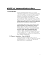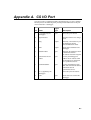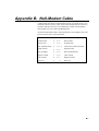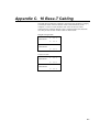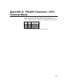
1
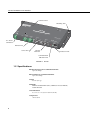
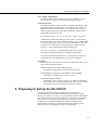
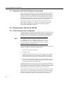
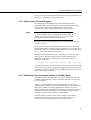
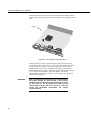
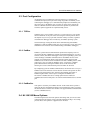
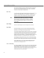
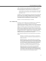
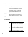
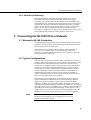
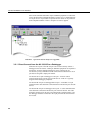
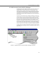
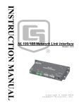
NL100/105 Network Link Interface Revision: 12/10 Logan, Utah NL10 NETW 0 ORK LINK INTER FACE POWE R G 12 V RS48 5 CS I/O MADE RS23 IN US A N NK 2 LA 5 LI RS48 SN: CS I/ O 10 BA SE T RS23 2 LAN LINK 10 B ASE T C o p y r i g h t © 2 0 0 0 - 2 0 1 0 C a m p b e l l S c i e n t i f i c , I n c . WARRANTY AND ASSISTANCE This equipment is warranted by CAMPBELL SCIENTIFIC (CANADA) CORP. (“CSC”) to be free from defects in materials and workmanship under normal use and service for twelve (12) months from date of shipment unless specified otherwise. ***** Batteries are not warranted. ***** CSC's obligation under this warranty is limited to repairing or replacing (at CSC's option) defective products. The customer shall assume all costs of removing, reinstalling, and shipping defective products to CSC. CSC will return such products by surface carrier prepaid. This warranty shall not apply to any CSC products which have been subjected to modification, misuse, neglect, accidents of nature, or shipping damage. This warranty is in lieu of all other warranties, expressed or implied, including warranties of merchantability or fitness for a particular purpose. CSC is not liable for special, indirect, incidental, or consequential damages. Products may not be returned without prior authorization. To obtain a Return Merchandise Authorization (RMA), contact CAMPBELL SCIENTIFIC (CANADA) CORP., at (780) 454-2505. An RMA number will be issued in order to facilitate Repair Personnel in identifying an instrument upon arrival. Please write this number clearly on the outside of the shipping container. Include description of symptoms and all pertinent details. CAMPBELL SCIENTIFIC (CANADA) CORP. does not accept collect calls. Non-warranty products returned for repair should be accompanied by a purchase order to cover repair costs. PLEASE READ FIRST About this manual Please note that this manual was originally produced by Campbell Scientific Inc. (CSI) primarily for the US market. Some spellings, weights and measures may reflect this origin. Some useful conversion factors: Area: 1 in2 (square inch) = 645 mm2 Length: 1 in. (inch) = 25.4 mm 1 ft (foot) = 304.8 mm 1 yard = 0.914 m 1 mile = 1.609 km Mass: 1 oz. (ounce) = 28.35 g 1 lb (pound weight) = 0.454 kg Pressure: 1 psi (lb/in2) = 68.95 mb Volume: 1 US gallon = 3.785 litres In addition, part ordering numbers may vary. For example, the CABLE5CBL is a CSI part number and known as a FIN5COND at Campbell Scientific Canada (CSC). CSC Technical Support will be pleased to assist with any questions. NL100/105 Table of Contents PDF viewers note: These page numbers refer to the printed version of this document. Use the Adobe Acrobat® bookmarks tab for links to specific sections. 1. Introduction..................................................................1 1.1 Physical Description of the NL100/105 ...................................................1 1.2 Specifications............................................................................................2 2. Preparing to Set Up the NL100/105 ............................3 2.1 Computer to NL100/105 Physical Connection .........................................4 2.2 Communication with the NL100/105 .......................................................4 2.2.1 Setup Using the Device Configurator .............................................4 2.2.2 Setup Using a Terminal Program....................................................5 2.2.3 Establishing Communication Outside of ConfMon Mode..............5 2.3 Port Configuration ....................................................................................7 2.3.1 TCPSer............................................................................................7 2.3.2 PakBus ............................................................................................7 2.3.3 PakBusSer.......................................................................................7 2.4 NL100/105 Menu Options........................................................................7 2.4.1 Ver ..................................................................................................8 2.4.2 Show ...............................................................................................8 2.4.3 Edit..................................................................................................8 2.4.3.1 TLink Config.........................................................................8 2.4.3.2 RS485 Config........................................................................9 2.4.3.3 CS I/O Config .....................................................................10 2.4.3.4 RS-232 Config ....................................................................12 2.4.3.5 Ethernet 10 Base-T..............................................................14 2.4.3.6 PakBus Address of the NL100/105.....................................15 2.4.3.7 PakBus/Tcp Server Config..................................................15 2.4.3.8 PakBus/Tcp Client Config...................................................16 2.4.3.9 MODBUS/TCP Gateway Config ........................................16 2.4.3.10 Telnet IP Port Number ......................................................16 2.4.3.11 DevConfig Security Code .................................................16 2.4.4 Defaults.........................................................................................17 2.4.5 Reset..............................................................................................18 2.4.6 Help...............................................................................................18 2.4.7 Bye ................................................................................................18 2.4.8 Other Commands ..........................................................................18 2.4.9 Serial Server Watchdog ................................................................19 3. Connecting the NL100/105 to a Network .................19 3.1 Network to NL100 Connection ..............................................................19 3.2 Typical Configurations ...........................................................................19 3.2.1 Direct Connect from the NL100/105 to a Datalogger...................20 3.2.2 MD9 Connection from NL100/105 to Datalogger........................21 3.2.3 MD485 Connection from NL100/105 to Datalogger....................22 3.2.4 RF Connection from NL100/105 to Datalogger ...........................22 3.2.5 Short Haul Modem Connection from NL100/105 to Datalogger .23 i NL100/105 Table of Contents 3.2.6 Phone Modem Connection from NL100/105 to Datalogger ........ 23 3.3 NL100/105 to Datalogger Connections - CR9000/CR5000 .................. 24 3.3.1 Software Setup ............................................................................. 24 3.3.2 Hardware Setup for NL105 Communication with the CR9000 via TLink ...................................................................................... 25 Appendices A. CS I/O Port ............................................................... A-1 B. Null-Modem Cable ................................................... B-1 C. 10 Base-T Cabling ...................................................C-1 Glossary Figures 1. 2. 3. 4. 5. 6. 7. NL100 ........................................................................................................ 2 NL100/105 Jumper Placement................................................................... 6 Typical NL100/105 Setups in LoggerNet................................................ 20 LoggerNet Setup for NL100/105 to MD9 to Datalogger Connection ..... 21 LoggerNet Setup for NL100/105 to RF to Datalogger Connection......... 23 LoggerNet Setup for NL100/105 to Phone to Datalogger Connection.... 24 PC9000 Setup for TCP/IP Communication ............................................. 25 ii NL100/105 Network Link Interface 1. Introduction The NL100 and NL105 Network Link Interfaces are devices used to communicate with Campbell Scientific dataloggers using an Ethernet 10 BaseT communications link. The NL100 includes a CS I/O port (see Appendix A) an RS-232 port, and an RS-485 port for communication; the NL105 adds a TLink interface for communication with a CR9000(C) system. The NL100/105 can be configured to act as a Serial Server in a standard TCP/IP network, to act as a PakBus node in a PakBus network, or to transfer MODBUS/TCP packets. All of the available settings are described in Section 2.4. However, not all settings are required for all configurations. This manual will focus mainly on setting up the NL100/105 for a standard TCP/IP network. For PakBus and MODBUS configurations, please contact Campbell Scientific for applications notes or other information that may be available. Campbell Scientific's LoggerNet software is used to communicate with the dataloggers once the NL100/105 is configured properly and connected to a network (refer to Section 2.). Communication with CSI’s mixed-array dataloggers (CR10X, CR510, CR23X, CR7, and 21X) and table-data dataloggers (CR10X-TD, CR510-TD, CR23X-TD, CR5000, and CR9000) requires LoggerNet version 2.0 or greater. Communication with CR10XTDPB, CR510TD-PB, CR23XTD-PB, and CR200 dataloggers requires LoggerNet 2.1 or greater. Communication with the CR1000 requires LoggerNet 3.0 or greater. Communications with the CR3000 require LoggerNet 3.2 or greater and with the CR800 and CR850 require LoggerNet 3.3 or greater. PC208W version 3.2 or higher may also be used with mixed array dataloggers (CR10X, CR510, CR23X, CR7, 21X). PC9000 may also be used for CR9000 and CR5000 dataloggers. 1.1 Physical Description of the NL100/105 The NL100/105 is housed in a rectangular case with all power and communication connections on one edge. On the opposite outside edge are tabs for mounting the NL100/105 in an enclosure. Figure 1 below shows the position of these connections and the mounting tabs. 1 NL100/105 Network Link Interface Corner Screws Mounting Tabs Logan, Utah NL10 NETW 0 ORK LINK INTER FACE POWE R G 12 V RS48 5 SN: RS48 5 CS I/O MADE RS23 LA LI 12 V Power Connection IN US A N NK 2 CS I/ O 10 BA SE T RS23 2 RS-485 Ports LAN LINK 10 B ASE T RS-232 DTE Port CS I/O Port 10 Base-T Link Communication Indicator LEDs FIGURE 1. NL100 1.2 Specifications RS-485 and CS I/O Port Communication Rate Up to 38.4 kbps RS-232 DTE Port Communication Rate Up to 115.2 kbps Weight 13.3 oz (377 g) Standards Ethernet Standard IEEE 802.3 (CSMA/CD Access Method) TCP/IP Protocol Case Dimensions 9 ¼” x 4 ¼” x 1” (23.5 x 10.8 x 2.54 cm) Temperature -25 to +50qC 2 NL100/105 Network Link Interface Power Supply Requirements The NL100/105 is powered via the green G 12V connector (11 to 16 VDC at 140 mA average current) on the front panel of the unit. Cable Specifications The Ethernet 10 Base-T cable should be a Category 5 twisted pair cable. Campbell Scientific recommends the 13658. The two active pairs in an Ethernet 10 Base-T network are pins 1 & 2 and pins 3 & 6. Use only dedicated wire pairs (such as blue/white & white/blue, orange/white & white/orange) for the active pairs. RJ-45 Pin-Outs: Pin 1 = TD+, Pin 2 = TD-, Pin 3 = RD+, Pin 6 = RDA DB9 female to DB9 male cable such as the 10873 is used to connect the NL100’s RS-232 port to the datalogger’s RS-232 port. A DB9 female null modem cable such as the 13657 is used to connect the NL100’s RS232 port to a PC’s RS-232 port. The RS-232 cable should be kept at lengths of d 6 feet to maintain high data throughput rates. The CS I/O 9 Pin cable is a straight through cable with all 9 pins connected. Campbell Scientific’s SC12 cable is recommended. The cable for the RS-485 connection is a 2 twisted pair, 22 awg cable. CSI recommends the CABLE3CBL-L for use with the MD485s. Compliance The NL100/105 is encased in metal and meets requirements for a Class A device under European standards: APPLICATION OF COUNCIL DIRECTIVE(S) 89/336/EEC as amended by 89/336/EEC and 93/68/EEC. STANDARD(S) TO WHICH CONFORMITY IS DECLARED: ENC55022-1; 1995 AND ENC 50082-1: 1992 EUROPEAN REGULATIONS WARNING: This is a Class A product. In a domestic environment this product may cause radio interference in which case the user may be required to correct the interference at the user’s expense. 2. Preparing to Set Up the NL100/105 The NL100/105 must be set up by configuring one or more of the communications ports for communication with your datalogger or other devices in the network. To do this, you must establish a direct communication link with the NL100/105 using a PC computer. You will need a null modem cable to physically connect the NL100/105 to the computer. The Device Configurator or a terminal communication software package (such as HyperTerminal, which ships with Microsoft Windows operating system software) is used to configure the settings in the NL100/105. 3 NL100/105 Network Link Interface 2.1 Computer to NL100/105 Physical Connection An RS-232 null-modem cable is required to establish communication between the NL100/105 and your computer. One end of the cable is connected to the computer's 9-pin RS-232 communications port and the other end is connected to the RS-232 port of the NL100/105. If the null-modem cable does not have a female connector on both ends, you may also need a female-to-female adapter. For additional information on null-modem cables, refer to Appendix B. The NL100/105 requires 12 VDC for operation. This power source can be supplied by the datalogger's 12 V supply or by a regulated external power source. When connecting the power leads, the ground lead should be connected first and then the 12 V lead. 2.2 Communication with the NL100/105 2.2.1 Setup Using the Device Configurator Campbell Scientific's datalogger support software ships with a utility called the Device Configurator (or DevConfig). This tool is used to set up dataloggers and other devices for communication or to download a new operating system. DevConfig can also be downloaded from Campbell Scientific's web site. NOTE The NL100/105 must have at least operating system version 7 to be compatible with DevConfig's NL100 setup. If your NL100/105 does not have a compatible operating system, load a new one in using DevConfig's Send OS utility or use a terminal emulation program to set up the device. To use DevConfig to set up the NL100/105, first connect the NL100/105 to the computer as noted above and follow the steps below: 1. Remove power from the NL100/105. 2. Open DevConfig. 3. Highlight the NL100 in the list of devices which appears in the left-hand portion of the window. Select the COM port to which the NL100/105 is connected from the drop down list box at the bottom left of the window. 4. Press the Connect button and reapply power to the NL100/105. The device may take up to 60 seconds to respond to DevConfig, and for the current settings to be loaded into the Settings Editor. The Settings Editor is the active tab when you are first connected. Settings can be changed in this window by clicking within a field and entering a new value. If the value being set has a finite list of choices, a second click within the field will enable a drop down list box from which to select a valid option. DevConfig has built-in help for each setting, which is displayed at the bottom of the window. Use this information, along with Section 2.4 of this manual, to configure the settings for communication in your network. Once the settings have been defined, press Apply to save the changes to the NL100/105. 4 NL100/105 Network Link Interface You can also use the Terminal tab in DevConfig to set up the NL100/105 using the menus, as explained in the following section. 2.2.2 Setup Using a Terminal Program Once the physical connection has been made, communication can be established with the NL100/105 using a terminal communications package. The steps below demonstrate configuring the NL100/105 using HyperTerminal, which is shipped with Windows operating systems. NOTE The NL100/105 is shipped from the factory with its RS-232 port set in the ConfMon mode (configuration monitor). Refer to Section 2.2.3 if the RS-232 port has been set to some other configuration and direct communication is necessary. Ensure the NL100/105 has an appropriate power source applied. (Refer to Section 2.1, above.) Create a new connection in HyperTerminal. Choose the COM port to which the null-modem cable is connected, and set the baud rate to 115,200 bps. Most of the other settings can be left at the default (data bits = 8, parity = none, stop bits = 1). Flow control should be set to none. Once HyperTerminal indicates you are connected, press <Enter> a couple of times to gain the attention of the NL100/105. When communication is established, the current port settings will be returned, followed by the NL100/105 prompt line: NL100/105 (ver, show, edit, defaults, reset, help, bye): To set up the NL100/105 for communication with the network, go into the Edit menu (Section 2.4.3 Edit) and complete the appropriate information. Note that the Ethernet 10 Base-T connection must be configured (Section 2.4.3.5) and at least one of the other port options. 2.2.3 Establishing Communication Outside of ConfMon Mode If the RS-232 port has been disabled or set to some configuration other than ConfMon, communication can still be established with the NL100/105 using one of two options. When power is first applied to the NL100/NL105, there is a 0.5-second window in which communication can be established with the NL100 using the RS232 port, regardless of the port's configuration. Therefore, if power is already applied, simply disconnect power and then reconnect it, then attempt to establish communication within the 0.5-second period. Holding down the enter key should allow you to hit this 0.5-second window. The other option is to connect a boot jumper, which bypasses the boot sequence of the NL100/105. To access the boot jumper, remove the NL100/105's cover by removing the four screws at the corners. 5 NL100/105 Network Link Interface The boot jumper is shown in Figure 2 below. The NL100/105 ships with this jumper connected to only one post. Place the jumper so that it connects the two posts. Jumper FIGURE 2. NL100/105 Jumper Placement When the jumper is in place, open the HyperTerminal connection to the NL100/105 and power up the device. The prompt "NL100 boot" will appear. At this prompt, press <Enter> a few times to ring up the NL100/105. If communication is successfully established, a message will be returned indicating that the NL100/105 is initialized, along with the jumper setting (1 = on, 0 = off), the TCP/IP address, Telnet port address, and current communication configuration. If <Enter> is pressed again, the NL100/105 menu prompt will appear. WARNING 6 After reconfiguring the NL100/105 for communication, the jumper should be disconnected. If this jumper remains in place and power to the NL100/105 is cycled off and back on, the NL100/105 will remain at the "NL100 boot" prompt and will not boot up. This will render the NL100/105 inaccessible via remote communications. NL100/105 Network Link Interface 2.3 Port Configuration An important step in configuring an NL100/105 for use is setting up the communication port(s) that you will be using. Regardless of whether you are connecting the datalogger (or a communication peripheral) to the RS485 port, the CS I/O port, or the RS232 port, you must set up the port to support the mode of communication that will be used for that portion of your network. The three options supported are explained briefly, below. 2.3.1 TCPSer When the port is set to TCPSer, it will act as a TCP serial server. Any packet that is transmitted via the port will be sent using the TCP/IP protocol. This is the simplest way to set up a port and will work in many scenarios, regardless of whether the datalogger has a mixed-array or PakBus operating system. One disadvantage of using this mode when communicating with PakBus dataloggers is that no PakBus routing can occur via the port. It may also be less efficient in some instances when communicating with PakBus dataloggers. 2.3.2 PakBus PakBus is a packet-based communications protocol developed by CSI. It is used in the CR1000, CR800/850, CR3000, and CR200 dataloggers, as well as CR10X, CR510, and CR23X dataloggers with a special operating system. One of the advantages of PakBus communication is that PakBus devices in the network can communicate directly with and route packets between other PakBus devices in the network. In addition to the native PakBus packets, other packet types, such as TCP/IP or ModBus, can be “wrapped” in a PakBus packet and transferred among the PakBus devices in the network, thus allowing for various communication protocols within one network. By configuring a port for PakBus communication, the NL100/105 is set up as a PakBus router in the network. The NL100/105 can then route packets to other devices in the network that it has “learned” about through beaconing or PakBus neighbor filters. When a port is configured for PakBus, the NL100/105’s PakBus/TCP Server Config option must be enabled or communication will not take place via TCP/IP with the PakBus devices on that port. 2.3.3 PakBusSer This option is used only in a PakBus network. In this mode when a packet is routed out the port, the PakBus framing is removed from the packet. Typically, the attached device would be one that does not support PakBus communication (such as a ModBus device). 2.4 NL100/105 Menu Options The following discusses the menu options and settings that you will see when connected to the NL100/105 using a terminal emulation package. DevConfig provides these same options in a graphical user interface. 7 NL100/105 Network Link Interface The NL100/105 prompt lists all of the available menu options. Only the first few characters of the main menu options need to be typed – the remaining characters will be completed automatically. Press <Enter> to execute the command. Each menu option is explained below. 2.4.1 Ver Ver returns version information about the NL100/105. The ROM number, OS version, Ethernet physical address, and some diagnostic statistics are displayed. Version information may be requested by a Campbell Scientific Applications Engineer when troubleshooting a communication problem. NOTE The Ethernet physical address that is displayed is a hexadecimal representation of the address assigned to this device. An Ethernet address is unique to the specific device to which it is assigned. This assignment is made at the factory and cannot be changed by the user. The Ethernet physical address is not the same as the TCP/IP address. 2.4.2 Show The Show command displays the current settings for the NL100/105. 2.4.3 Edit The Edit menu option is used to set up the communications link for the NL100/105. You should work closely with your network administrator to determine the correct settings for your specific network. You can progress through the menu options by pressing <Enter>. If you make a mistake after entering a setting, press the up cursor arrow on your keyboard to return to the previous setting. All available selections will be listed on the prompt line enclosed in parentheses, with the current setting displayed in brackets at the end of the selections (e.g., [disabled]). Help for a setting can be displayed by entering the ? key and pressing <enter>, or by pressing F1. Once changes have been made and you have come to the end of the prompts for the communication options, you can choose "save" to put the new settings into effect or "cancel" to disregard the changes and keep the current settings. Prior to configuring one or more of the ports for communication (TLink Config, RS485 Config, CS I/O Config, or RS232 Config) refer to the discussion on Port Configuration above. 2.4.3.1 TLink Config This setting is applicable to the NL105 only, and is used when communicating with a CR9000 datalogger. TLink is an interface used to communicate with a CR9000 datalogger over an Ethernet connection. A physical connection is made between the TLink port on the CR9000's 9031 CPU module and the port marked TLink on the NL105. TLink Config is used to set the TLink communications port to one of three options: 8 NL100/105 Network Link Interface TcpSer - The NL105 acts as a serial server for the TLink port. A serial server is a device that allows serial communication over a TCP/IP communications link. When configured as a serial server, there is one parameter to set: TLink Serial Server Port Number - Enter the port number, in the range of 3000 to 65000, that will be used for TLink communication. The default port number is 6781. 232-Bridge - The NL105 transparently passes data between the TLink port and its RS-232 ports. The 232-Bridge configuration has only one setting, RS-232 bps. This is the bits per second (bps) at which the NL105 will communicate with the device connected to the RS-232 port. This is a fixed rate (i.e., it is not a maximum baud rate or an autobaud rate). The default is 115k bps. Disabled - The TLink communications port is disabled. 2.4.3.2 RS485 Config This option is used to configure the NL100's RS485 port for communication with an RS485 device. Campbell Scientific offers the MD485 for communication with its dataloggers via RS485. The port can be configured for PakBus communication, as a TcpSer serial server, or as a PakSer serial server. PakBus - This option is used to set up the NL100/105 to communicate with PakBus devices over the RS485 port. Packets transferred over the port in this mode are framed as PakBus packets; therefore, any device attached to the port must be configured for PakBus communication also. When a port is configured for PakBus, the NL100/105’s “PakBus/Tcp Server Config” option must be enabled (Section 2.4.3.7) or you will not be able to communicate with TCP/IP through the NL100/105 to the PakBus devices on that port. When configured for PakBus the NL100/105's RS485 port has the following settings: RS485 Bps - This option is used to set the bits per second (bps) at which the NL100/105 will communicate using the RF485 port. The default value is 38K. RS485 Beacon Interval - The NL100/105 can be set to transmit a beacon to a PakBus network via the selected port. The beacon allows the NL100/105 to determine which devices in the PakBus network it can communicate with. Note that because a beacon is broadcast to all devices, it can interfere with other communication in the network (such as RF), so a frequent beacon may not be desirable. If 0 is entered, no beacon will be sent; the default beacon is 60 seconds. RS485 Verify Interval - This is the interval at which a PakBus communication link will be verified over the RS485 port. If communication does not take place with a PakBus device within the verify internal, a packet will be sent to test the communication link. In most instances, this setting should be left at the default of 0, which will set a verify interval of 2.5 times the Beacon Interval. 9 NL100/105 Network Link Interface If both the beacon interval and verify interval are set to 0, a verify interval of 5 minutes will be used. RS485 Neighbor list - Enter a list of addresses for PakBus devices with which the NL100/105 can communicate over the RS485 port. The addresses are specified individually, with a space separating each address, or a range of addresses can be entered by separating them with a hyphen (e.g., 1 3 6 10-15, sets PakBus addresses 1, 3, 6, 10, 11, 12, 13, 14, and 15 as neighbors). If a Neighbor list is entered, the NL100/105 will ignore packets from any device which is not in the list (unless the address of the device sending the packet is 4000 or greater). If 0 is entered for this parameter, the NL100/105 will respond to any device that sends a packet and will automatically add that device to its neighbor list. TCPSer - This option configures the NL100 to act as a TCP/IP based serial server when communicating with the datalogger over its RS485 port. RS485 Bps - This is the bits per second (bps) at which the NL100/105 will communicate using the RS485 port. This is a fixed rate (i.e., it is not a maximum baud rate or an autobaud rate). The default rate is 38K bps. RS485 Serial server port number - Enter the port number, in the range of 1 to 65000, that will be used for communication. The default port number is 6782. PakSer - The RS485 port of the NL100/105 is configured as a PakBus serial server. RS485 Bps - This is the bits per second (bps) at which the NL100/105 will communicate using the RS485 port. This is a fixed rate (i.e., it is not a maximum baud rate or an autobaud rate). The default rate is 38K bps. RS485 serial server AppId Number - Enter the application ID, in the range of 1 to 65000, that will be used identify the device in the network. The default ID is 6782. NOTE The usual AppId for MODBUS devices is 502. 2.4.3.3 CS I/O Config This option is used to configure the NL100/105's CS I/O port. The port can be configured for PakBus communication, as a TcpSer serial server, or as a PakSer serial server. 10 NL100/105 Network Link Interface NOTE CR10X, CR510, CR23X, 21X, and CR7 dataloggers ship with a mixed array operating system. Mixed array dataloggers do not support the PakBus communications protocol. Therefore, you cannot communicate with them over a port configured for PakBus. However, the CR10X, CR510, and CR23X dataloggers can be special-ordered with a PakBus operating system. Check with your technical support representative for details. PakBus - This option is only used when setting up the NL100/105 to communicate with other PakBus devices in the network. Packets transferred over the CS I/O port in this mode are framed as PakBus packets; therefore, any device attached to the port must be capable of PakBus communication. When a port is configured for PakBus, the NL100/105’s “PakBus/Tcp Server Config” option must be enabled (Section 2.4.3.7) or you will not be able to communicate with TCP/IP through the NL100/105 to the PakBus devices on that port. When configured for PakBus, the NL100/105's CS I/O port has the following settings: CS I/O SdcAddr/bps - This option is used to set up the CS I/O port to communicate with the datalogger as an addressable SDC device or a modem enabled device. If SDC7 or SDC8 is chosen, the NL100/105 will use that address to communicate with the datalogger in a synchronous communication mode. If one of the baud rates is chosen, the NL100/105 will communicate with the datalogger as a modem enabled device using the selected baud rate. If another SDC device is connected to the NL100/105, the two devices must use different SDC addresses. CS I/O Beacon Interval - The NL100/105 can be set to transmit a beacon to a PakBus network via the selected port. The beacon allows the NL100/105 to determine which devices in the PakBus network it can communicate with. Note that because a beacon is broadcast to all devices, it can interfere with other communication in the network (such as RF), so a frequent beacon may not be desirable. If 0 is entered, no beacon will be sent; the default beacon is 60 seconds. CS I/O Verify Interval - This is the interval at which a PakBus communication link will be verified over the CS I/O port. If communication does not take place with a PakBus device within the verify internal, a packet will be sent to test the communication link. In most instances, this setting should be left at the default of 0, which will set a verify interval of 2.5 times the Beacon Interval. If both the beacon interval and verify interval are set to 0, a verify interval of 5 minutes will be used. NOTE A neighbor list is not specified because there is only one possible neighbor. TcpSer - This option configures the NL100 to act as a TCP/IP based serial server when communicating with the datalogger over its CS I/O port. 11 NL100/105 Network Link Interface CS I/O SdcAddr/bps - This option is used to set up the CS I/O port to communicate with the datalogger as an addressable SDC device or a modem enabled device. If SDC7 or SDC8 is chosen, the NL100/105 will use that address to communicate with the datalogger in a synchronous communication mode. If one of the baud rates is chosen, the NL100/105 will communicate with the datalogger as a modem enabled device using the selected baud rate. Note that mixed array dataloggers (CR10X, CR510, CR23X, 21X, CR7) can be configured only as modem enabled devices; e.g., they do not support communication using SDC7 or SDC8. CS I/O serial server port number - Enter the port number, in the range of 1 to 65000, that will be used for communication. The default port number is 6783. PakSer - The CS I/O port of the NL100/105 can be configured as a PakBus serial server. This sets up the device as a serial server. CS I/O SdcAddr/bps - This option is used to set up the CS I/O port to communicate with the datalogger as an addressable SDC device or a modem enabled device. If SDC7 or SDC8 is chosen, the NL100/105 will use that address to communicate with the datalogger in synchronous communication mode. If one of the baud rates is chosen, the NL100/105 will communicate with the datalogger as a modem enabled device using the selected baud rate. CS I/O Serial Server AppId number - Enter the application ID, in the range of 1 to 65000, that will be used to identify the device in the network. The default ID is 6783. NOTE The usual AppId for MODBUS devices is 502. 2.4.3.4 RS-232 Config This option configures the NL100/105's RS-232 port for communication. The port can be set up to communicate with a datalogger or other communications device (short haul modem, RF modem, phone modem), or to be connected to directly and configured for communication. The setup options for the port are PakBus, TcpSer serial server, PakSer PakBus serial server, or ConfMon (configuration monitor). NOTE CR10X, CR510, CR23X, 21X, and CR7 dataloggers ship with a mixed array operating system. Mixed array dataloggers do not support the PakBus communications protocol. Therefore, you cannot communicate with them over a port configured for PakBus. However, the CR10X, CR510, and CR23X dataloggers can be special-ordered with a PakBus operating system. Check with your technical support representative for details. PakBus - This option is only used when setting up the NL100/105 to communicate with other PakBus devices in the network. Packets transferred over the RS-232 port in this mode are framed as PakBus packets; therefore, any device attached to the port must be capable of PakBus communication. When a port is configured for PakBus, the NL100/105’s “PakBus/Tcp Server 12 NL100/105 Network Link Interface Config” option must be enabled (Section 2.4.3.7) or you will not be able to communicate with TCP/IP through the NL100/105 to the PakBus devices on that port. When configured for PakBus, the NL100/105's RS-232 port has the following settings: RS-232 bps - This is the bits per second (bps) at which the NL100/105 will communicate using the RS-232 port. This is a fixed rate (i.e., it is not a maximum baud rate or an autobaud rate). Note that the CR10XTD-PB and the CR510TD-PB can communicate at a maximum baud rate of 9600 bps, so to communicate with one of those dataloggers, this setting must be 9600 bps or less. The default rate is 115K bps. PakBus Beacon Interval - The NL100/105 can be set to transmit a beacon to a PakBus network via the selected port. The beacon allows the NL100/105 to determine which devices in the PakBus network it can communicate with. Note that because a beacon is broadcast to all devices, it can interfere with other communication in the network (such as RF), so a frequent beacon may not be desirable. If 0 is entered, no beacon will be sent; the default beacon is 60 seconds. RS232 Verify Interval - This is the interval at which a PakBus communication link will be verified over the RS232 port. If communication does not take place with a PakBus device within the verify internal, a packet will be sent to test the communication link. In most instances, this setting should be left at the default of 0, which will set a verify interval of 2.5 times the Beacon Interval. If both the beacon interval and verify interval are set to 0, a verify interval of 5 minutes will be used. RS232 Neighbor list - Enter a list of addresses for PakBus devices with which the NL100/105 can communicate over the RS232 port. The addresses are specified individually, with a space separating each address, or a range of addresses can be entered by separating them with a hyphen (e.g., 1 3 6 10-15, sets PakBus addresses 1, 3, 6, 10, 11, 12, 13, 14, and 15 as neighbors). If a Neighbor list is entered, the NL100/105 will ignore packets from any device which is not in the list (unless the address of the device sending the packet is 4000 or greater). If 0 is entered for this parameter, the NL100/105 will respond to any device that sends a packet and will automatically add that device to its neighbor list. TcpSer - This option configures the NL100 to act as a TCP/IP based serial server when communicating with a datalogger over its RS-232 port. RS-232 bps - This is the bits per second (bps) at which the NL100/105 will communicate using the RS-232 port. This is a fixed rate (i.e., it is not a maximum baud rate or an autobaud rate). Note that the CR10(X), CR510, and CR200 can communicate at a maximum baud rate of 9600 bps, so to communicate with one of those dataloggers, this setting must be 9600 bps or less. The default setting is 115K bps. 13 NL100/105 Network Link Interface RS-232 serial server port number - Enter the port number, in the range of 1 to 65000, that will be used for communication. The default port number is 6784. PakSer - The RS-232 port of the NL100/105 can be configured as a PakBus serial server. RS-232 bps - This is the bits per second (bps) at which the NL100/105 will communicate using the RS-232 port. This is a fixed rate (i.e., it is not a maximum baud rate or an autobaud rate). Note that the CR10(X), CR510, and CR200 can communicate at a maximum baud rate of 9600 bps, so to communicate with one of those dataloggers, this setting must be 9600 bps or less. The default setting is 115K bps. RS-232 Serial Server AppId number - Enter the application ID, in the range of 1 to 65000, that will be used to identify the device in the network. The default ID is 6784. NOTE The usual AppId for MODBUS devices is 502. ConfMon - Configuring the RS-232 port as a ConfMon allows you to connect directly to the NL100/105 via a computer. There are no parameters; the baud rate is automatically set to 115,200 bps. Refer to the previous information on setting up the NL100/105 for communication. 2.4.3.5 Ethernet 10 Base-T The 10 Base-T communications link is used to connect the NL100/105 to a TCP/IP network using a Category 5 twisted pair cable. The Ethernet 10 Base-T link must be configured or you will not be able to communicate with the NL100/105 over a TCP/IP connection. The following options must be configured. These values should be provided by your network administrator. 10BASE-T Port IP Address - This number is the address of the NL100/105 on a TCP/IP network. It is written as 32-bit number written in four 8-bit decimal-equivalent syllables separated by periods, in the format XXX.XXX.XXX.XXX. The IP Address must be a static IP Address -- the NL100/105 does not support DHCP (dynamic host configuration protocol). 10BASE-T Port Network Mask - The network mask is used to help a network router to more efficiently transfer information. Typically, a class C mask will be 255.255.255.0, a class B mask will be 255.255.0.0, and a Class A mask will be 255.0.0.0. The tighter the mask, the more the NL100/105 will rely on the default gateway to route packets. IP Address of the Default Gateway - Enter the IP address of the device that is responsible for forwarding information to destinations outside the internal network, defined by the network mask. To disable a default gateway, use the default value of 0.0.0.0. 14 NL100/105 Network Link Interface 2.4.3.6 PakBus Address of the NL100/105 If the NL100/105 is to be used as a router in a PakBus network, a PakBus Address must be assigned. If the NL100/105 will not be used to route packets in a PakBus network, this setting can be ignored. All devices in the network must have a unique PakBus Address. Valid addresses are 1 through 4094. The default ID is 678. NOTE By default LoggerNet software uses PakBus Address 4094, PC400 uses 4093, PC200W uses 4092, and PConnect/ PConnectCE uses 4091. The use of these addresses in the NL100/105 should be avoided. PakBus addresses of greater than 3999 are typically reserved for PakBus routing devices and ports. This is because when a neighbor filter is set up in a PakBus datalogger, the datalogger will answer a Hello message from any device with an ID greater than 3999, but it will ignore devices with IDs less than 4000 that are not in their neighbor list. Clock Source Address - In a PakBus network, a "neighbor" is another PakBus device that the NL100/105 can communicate with directly (e.g., it does not have to route data through another PakBus device to reach the neighbor). A neighbor can be designated for the NL100/105 as the device from which the NL100/105 will accept a clock set command. If this setting is enabled, once the NL100/105 has received a clock set from its designated neighbor, it will broadcast its clock information along with its beacon. Thus, the NL100/105 can be used to set the clock of other PakBus devices in the network. Set this address to 0 to disable the function. Central Routers - The Central Routers setting is used to set up the NL100/105 either as a Central Router or a Branch Router. If 0 is used for this setting, then the NL100/105 is set up as a Central Router; otherwise, a list of Central Routers for the NL100/105 is entered and the device is set up as a Branch Router. While a Central Router learns the routes of all devices in the PakBus network, a Branch Router learns the routes for devices only within its branch. The use of Branch Routers allows branches of the network to be isolated from other branches. When the NL100/105 is set up as a branch router, the addresses for the Central Routers are specified individually with a space separating each address. A range of addresses can be entered by separating them with a hyphen (e.g., 1 3 6 10-15, sets PakBus addresses 1, 3, 6, 10, 11, 12, 13, 14, and 15 as Central Routers). 2.4.3.7 PakBus/Tcp Server Config This option enables the NL100/105 to use an Ethernet connection to communicate with other PakBus devices in the network. The NL100/105 can support up to 16 concurrent connections. The NL100/105 will listen for incoming TCP/IP packets on the socket designated by the PakBus/Tcp server port number setting. If the NL100/105 will not be used in a PakBus network, or if the PakBus communication among PakBus devices in the network will 15 NL100/105 Network Link Interface take place over a port other than the Ethernet connection, this setting can be disabled. When enabled, there is one option to configure: PakBus/TCP server port number - Enter the port number, in the range of 1 to 65000, that will be used for communication. The default port number is 6785. 2.4.3.8 PakBus/Tcp Client Config Enabling this option will set up the NL100/105 to act as a client in a PakBus network. In this mode, the NL100/105 will actively maintain a TCP/IP connection with a PakBus/Tcp server over the 10 Base-T connection. Server IP Address - The Server IP address is the address of the server to which the NL100/105 will attempt to connect and act as a client. Server IP Port Number - The Server IP port number is used to specify the port number of the PakBus/TCP server to which the client will attempt to connect. This option is typically used when the NL100/105 is configured to communicate with another NL100/105 over an Ethernet connection, so that the two PakBus networks served by the NL100/105s can be merged. In most situations, this setting can be disabled. 2.4.3.9 MODBUS/TCP Gateway Config When this setting is enabled, the NL100/105 will translate MODBUS/TCP packets that arrive on the 10 Base-T link for use in a PakBus network. The translation provided by this mode is MODBUS/TCP message format to MODBUS RTU serial message format. Unless you are setting up a PakBus network to also handle MODBUS communication packets, this setting can be disabled. 2.4.3.10 Telnet IP Port Number This setting is used to specify the IP port number that will be used for Telnet sessions with the NL100/105. The default value is 23. Telnet Session Password - The Telnet Session Password is the string that must be entered to communicate with the NL100/105 over a Telnet session. The string can range from 1 to 20 alphanumeric characters and is case-sensitive. This security measure is implemented to help prevent unauthorized users from gaining access to the NL100/105 device. 2.4.3.11 DevConfig Security Code Campbell Scientific's Device Configurator (or DevConfig) is an application that is used to configure dataloggers and peripheral devices for communication and to download new operating systems. A security code can be set in the NL100/105 so that communication using DevConfig is not possible unless the security code is sent when the application tries to communicate with the device. This security code helps to prevent unauthorized changes to a device. 16 NL100/105 Network Link Interface By default the address is 0. To enable security, enter a value between 1 and 65535. 2.4.4 Defaults The Defaults option displays the factory default settings for the different telecommunication options. Following the display is a prompt to Save or Cancel. If Save is selected, the NL100/105 will be reset to the factory defaults. If Cancel is chosen, the current settings will remain in effect and the user will be returned to the main menu prompt. The default settings are as follows: TLink config: [disabled] RS485 config: [disabled] CS I/O config: [Tcp Ser] CS I/O SdcAddr/bps: [9600] CS I/O serial server port number [6783] RS-232 config: [ConfMon] EtherNet 10BASE-T: [enabled] 10BASE-T port IP address: [192.168.111.222] 10BASE-T port network mask: [255.255.0.0] IP address of the default gateway: [0.0.0.0] PakBus Address of the NL100/105: [678] Clock source address: [0] Central Routers: [0] PakBus/Tcp server config: [disabled] PakBus/Tcp client config: [disabled] MODBUS/TCP gateway config: [disabled] Telnet IP port number: [23] Telnet session password: [nl100] DevConfig security code: [0] This option is different from the Reset menu item. The Default menu item resets the NL100/105 back to the factory defaults. Reset reboots the device using the last-saved configuration. After the NL100/105 reboots, it may take a few moments to reestablish communication. Press enter a few times until the NL100/105 status line is returned. 17 NL100/105 Network Link Interface 2.4.5 Reset This option reboots the NL100/105, using the last saved settings that have been programmed by the user. This option is different from the Defaults menu item. The Defaults menu item resets the NL100/105 back to the factory defaults. After the NL100/105 reboots, it may take a few moments to reestablish communication. Press enter a few times until the NL100/105 status line is returned. NOTE When using the NL100/105 in a PakBus network, resetting the NL100/105 (or making other changes to the network that might change the known route to remotes), may result in lengthy communication interruptions until the new routes can be learned by all the devices in the network. 2.4.6 Help The Help option provides tips for navigating within the NL100/105 menu prompts and gives a brief description of each menu item. Help for a particular setting can be displayed by pressing F1 or ? at the prompt for that setting. 2.4.7 Bye The Bye option is used to close the Socket connection at the end of a Telnet or terminal communication session. 2.4.8 Other Commands Additional commands are available for the NL100/105, which are not shown on the prompt line for the device or in DevConfig. The commands are used for troubleshooting. 18 Command Description io This command is a toggle, which turns on or off the monitoring of low level I/O o (or old) This command shows historic diagnostic trace information for the NL100/105. The object handle, name, and state are provided for all active objects and the object handle, name, and event type are provided for all recent events. c (or current) This command shows current diagnostic trace information for the NL100/105. The object handle, name, and state are provided for all active objects and the object handle, name, and event type are provided for all recent events. t (or tables) This command displays the PakBus routing table information for the NL100/105: NL100/105 Network Link Interface 2.4.9 Serial Server Watchdog If no communication is detected for a specified number of minutes, the NL100/105 will drop the communications link. This feature is called a "watchdog". The watchdog alleviates the problem of a communications port being held open, thus rendering the device inaccessible, if the NL100/105 and the remote device failed to terminate the communications link in a "normal" manner. The NL100/105 will wait two minutes for activity on a port before timing out. This affects all communication modes, including when the NL100/105 is configured as a PakBus based or TCP/IP based serial server, and when communicating with the NL100/105 during a Telnet session. 3. Connecting the NL100/105 to a Network 3.1 Network to NL100 Connection The connection from the computer network to the NL100/105 10 Base-T port should be a twisted pair cable. A male RJ-45 plug connector should be on the cable end going into the 10 Base-T port. If the cable is to be run directly from the computer to the NL100/105, a crossover cable is required. If the cable will be run from a hub to the NL100/105, a straight through cable should be used. Appendix C shows the pin-outs for these two cable types. 3.2 Typical Configurations The cases below assume the NL100/105 is being connected to a mixed array datalogger using the datalogger's CS I/O port (CR10X, CR510 CR23X) or RS232 port (CR23X). TD-based dataloggers (CR10X-TD, CR510-TD, and CR23X-TD) are configured similarly. In these instances, the communication port(s) being used on the NL100/105 should be set up as TcpSer (TCP/IP based serial server). When communicating with PakBus devices (CR1000, CR3000, CR800/850, CR200, CR10XPB, CR510PB, or CR23XPB), the communication port on the NL100/105 can be configured for PakBus or TcpSer, depending upon the role the NL100/105 is to play in the network. In many cases, the TcpSer option can be selected. For mixed array and TD dataloggers, the network map for the LoggerNet software should depict an IPPort root device with the datalogger attached directly to the IPPort (see Figure 3) unless otherwise noted. For PakBus dataloggers, a PakBus Port must first be added to the IP Port in the network map, and then the PakBus datalogger attached to the PakBus Port. In instances where the NL100/105 is to be a PakBus router, a pbRouter must be added after the PakBus Port and before the PakBus datalogger. In some instances, extra response time (3 to 4 seconds) may need to be added to the IPPort and/or the datalogger to account for network traffic delays over a TCP/IP connection. NOTE The IP Address entered in the software for the NL100/105 should not contain leading zeros. If leading zeros are used, the communications attempts will fail. 19 NL100/105 Network Link Interface Some of the communication links require additional peripherals or cables that can be purchased from Campbell Scientific. In some cases, a standard RS-232 9 to 25 pin or 25 to 25 pin cable is required. RS-232 cables can be purchased from Campbell Scientific or from a computer accessories supplier. FIGURE 3. Typical NL100/105 Setups in LoggerNet 3.2.1 Direct Connect from the NL100/105 to a Datalogger Either the CS I/O port or the RS-232 port can be used to directly connect a datalogger to the NL100/105. Cabling or additional peripherals are required as listed below. Note that multiple dataloggers can be connected to one NL100/105 by using combinations of the connections described below. Each port must be assigned a unique port number. NL100/105 CS I/O port to datalogger CS I/O port - An SC12 cable is connected between the CS I/O ports on both devices. An SC12 is typically shipped with all datalogger peripherals. NL100/105 RS-232 port to datalogger RS-232 port - A standard 9 to 9 pin communications cable should be connected between the RS-232 ports on both devices. NL100/105 RS-232 port to datalogger CS I/O port - A serial communications cable should be connected to the RS-232 port of the NL100/105. This cable should be connected to an SC32A or SC32B optically isolated interface, and the datalogger should be connected to the 9 pin port of the SC32A/B with an SC12 cable. 20 NL100/105 Network Link Interface 3.2.2 MD9 Connection from NL100/105 to Datalogger Campbell Scientific's MD9 Multidrop Interface can be used to connect one or more dataloggers to the NL100/105 via the NL100/105’s RS-232 port. A multidrop network is capable of addressing up to 254 dataloggers, but the actual number of dataloggers that can be connected depends upon attenuation of the signal due to coax cable length, the number of devices on the network, and the number of coax terminator pairs used. Refer to the MD9 manual for determining the maximum number of dataloggers that can be connected based on these factors. An SC532 or SC532A Interface device should be connected to the serial port of the NL100/105. The cable to an SC532 should be a standard 9 to 25 pin RS232 cable, with the 25 pin male connection mated to the RS-232 side of the SC532. The cable to an SC532A should be a standard 9 to 9 pin RS-232 cable. Note, however, that the RTS line in the cable must be disabled (pin 7 on the 9pin connector or pin 4 on the 25-pin connector). An SC12 cable is used to connect the 9 pin peripheral connection of the SC532/SC532A to the serial I/O port of the MD9. Coax cable, running from the coax port of the base MD9, is run to each of the remote MD9 devices, which are connected to the dataloggers with SC12 cables. Refer to the MD9 User's Manual for additional information. The Setup window in LoggerNet should depict an MD9 Base modem attached to the IPPort, with the datalogger attached to an MD9Remote Modem. Refer to Figure 4 below. FIGURE 4. LoggerNet Setup for NL100/105 to MD9 to Datalogger Connection 21 NL100/105 Network Link Interface 3.2.3 MD485 Connection from NL100/105 to Datalogger Campbell Scientific's RS485 communication device, the MD485, can be attached to an NL100/105 to provide a communication link to one or more dataloggers. The MD485 has three communication ports: RS485 (two terminals but the same physical port), CS I/O, and RS232. It can be configured for communication on any two of its three ports at one time. The most typical use of the MD485 is to set up a network of dataloggers linked together in an RS485 network. However, you can also attach a datalogger or other compatible peripheral to the CS I/O port or the RS-232 port of the MD485. The MD485 can be configured to communicate in a transparent (point to point) mode, as an MD9 emulator, or as a peripheral in a PakBus network. For transparent or PakBus communication, the MD485 is attached to the NL100/105's RS485 port using a 3-wire shielded cable (i.e., a 2 twisted pair shielded cable). For MD9 emulation, at least two MD485s are required. One MD485 is attached to the NL100/105's RS232 port using an SC12 cable. This MD485 acts as a base MD9 device, since the NL100/105 is, in itself, not capable of MD9 communication. A second MD485 is attached to each of the dataloggers. An appendix in the MD485 manual provides complete information on setting up the NL100/105 and the MD485s for each of the above configurations, along with information on the settings used in LoggerNet. 3.2.4 RF Connection from NL100/105 to Datalogger Interfacing the NL100/105 to an RF Base station enables wireless communication to remote datalogger stations over a TCP/IP network. The preferred configuration uses the NL100/105's RS-232 port (DTE) for connection to the RF Base as follows: For connecting to the RS-232 port (DCE) of the RF4xx series or RF450 Spread Spectrum radios, a standard RS-232 serial cable (CSI# 10873 or equivalent) is used. For connecting to the RS-232 port (DTE) on an RF500M RF Modem, a nullmodem RS-232 serial cable (CSI# 13657 or equivalent) must be used. If connecting to the CSI/O port on the RF500M, an SC532A 9-Pin Peripheral to RS-232 interface adapter and standard serial cables are required. NOTE When connecting to an RF310B Base Station or its predecessors (or directly to an RF310M RF Modem via an SC532A), the RTS line in the standard RS-232 serial cable (pin seven on a 9-pin connector or pin four on a 25-pin connector) must be disabled. This is done to prevent driving the SDE signal (pin 6) on the RF Modem's CSI/O port high and inhibiting the ME communication cycle. If circumstances should require the utilization of the NL100/105's CS I/O port for connection to an RF base, please contact a Campbell Scientific Applications Engineer for information about how this might be achieved. The configuration of the Setup window in LoggerNet will vary depending on the equipment and configuration settings employed. Please consult the relevant manual(s) for configuration specifics. Figure 5 depicts the LoggerNet 22 NL100/105 Network Link Interface Setup window for an RF Network using VHF/UHV radios and a mixed array datalogger. FIGURE 5. LoggerNet Setup for NL100/105 to RF to Datalogger Connection Refer to Campbell Scientific's Radiotelemetry Network Instruction Manual for more information on setting up RF stations. 3.2.5 Short Haul Modem Connection from NL100/105 to Datalogger The use of Short Haul Modems (SRM-5A, SRM6-A) allows a connection to a datalogger via TCP/IP to a twisted pair cable. The short haul modem at the NL100/105 should be connected to the device using a standard RS-232 9 to 25 pin communication cable. It is recommended that a short haul surge protection device (P/N 5563) be connected next and then the twisted pair cable. Another surge protection device is recommended between the cable and the remote short haul modem. The short haul modem should be connected to an SC932 RS-232 9 to 25 pin DCE interface, which is then connected to the datalogger's CS I/O port via an SC12 cable. 3.2.6 Phone Modem Connection from NL100/105 to Datalogger A Hayes-compatible phone modem can be connected to the NL100/105 to allow a TCP/IP to phone link between a computer and a datalogger. The phone modem should be connected to the NL100/105's RS-232 port using an appropriate RS-232 serial cable. Connection of the remote phone modem to the datalogger will vary, depending upon the type of remote modem used. Refer to the user's manual for the system you purchased for additional information on assembling the remote site. 23 NL100/105 Network Link Interface In the LoggerNet communications software, the phone modem on the NL100/105 side should be shown attached to the IPPort. The datalogger is then shown as connected to the remote phone modem. Refer to Figure 6 below. FIGURE 6. LoggerNet Setup for NL100/105 to Phone to Datalogger Connection 3.3 NL100/105 to Datalogger Connections - CR9000/CR5000 3.3.1 Software Setup As an alternative to LoggerNet, PC9000 software (version 3.5 or higher) can be used to communicate with the CR9000 and CR5000 dataloggers via the NL100/105 and a TCP/IP Network. To configure the software for communication, choose the Tools | CommLink menu option. From the I/O Port drop-down list box, select NET. On the bottom left side of the screen, there are fields in which to type the TCP/IP address and the port number. The setup should look similar to Figure 7, below. 24 NL100/105 Network Link Interface FIGURE 7. PC9000 Setup for TCP/IP Communication 3.3.2 Hardware Setup for NL105 Communication with the CR9000 via TLink A CR9000 can be connected to a TCP/IP network by connecting the TLink port of the CR9000 9031 CPU module to the TLink port of the NL105 (note that the NL100 does not have this communication port). A twisted pair cable is used to make this connection. 25 NL100/105 Network Link Interface 26 Appendix A. CS I/O Port The CS I/O port is Campbell Scientific's input/output port. It is not a standard RS-232 pin-out. The following table provides pin-out information on the port when connected to a datalogger. Pin Name Signal Type Description Input Not used by NL100/105 1 5 V (supplied by the datalogger) 2 Signal Ground 3 Ring Output Raised by a NL100/105 to put the datalogger into the telecommunications mode 4 RXD Output Serial data transmitted to the datalogger 5 Modem Enable Input Raised by the datalogger when it determines that the NL100/105 raised the ring line 6 Synchronous Device Enable Input Used by the datalogger to address the NL100/105 when the NL100/105 is configured as a synchronous device 7 Clock/Handshake Input Used by the datalogger with SDE and TXD lines to address and transfer data to synchronous devices 8 12 V (supplied by the datalogger) 9 TXD Provides reference for voltage levels Not used by the NL100/105 Input Serial data received from the datalogger A-1 This is a blank page. Appendix B. Null-Modem Cable A null-modem cable allows communication between two similar devices. It is sometimes called a crossover cable, because the transmit and receive lines are crossed so that the two devices can communicate. An RS-232 null modem cable usually also crosses other handshaking lines. An RS-232 null-modem cable can be purchased at a local computer store. The pin-outs for this cable are provided below. Carrier Detect 1 4 Data Terminal Ready Transmit Data 2 3 Receive Data Receive Data 3 2 Transmit Data Data Terminal Ready 4 1, 6 Carrier Detect, Data Set Ready Signal Ground 5 5 Signal Ground Data Set Ready 6 4 Data Terminal Ready Request to Send 7 8 Clear to Send Clear to Send 8 7 Request to Send Not Used 9 9 Not Used B-1 This is a blank page. Appendix C. 10 Base-T Cabling The cable that runs from the computer to the NL100/105 should be a Category 5 twisted pair cable. If the NL100/105 will be connected directly to the computer, a crossover cable should be used. If the NL100/105 will be connected to the computer through a hub, a straight through cable should be used. The pin-outs for each of these cables is shown below. Straight Through Cable 1 1 2 2 3 3 6 6 1 3 2 6 3 1 6 2 Twisted Pair 1 Twisted Pair 2 Crossover Cable Twisted Pair 1 Twisted Pair 2 C-1 This is a blank page. Appendix D. RS-485 Connector, 3-Pin Terminal Block The RS-485 port is for connecting an MD485 multidrop interface to the NL100. The MD485 attaches to the NL100 via a twisted pair cable such as the #9720. The following table shows the pin-out information for the RS-485 port. PIN I/O FUNCTION 1 2 3 GND I/O I/O Signal Ground 485_IO- (A) 485_IO+ (B) I = Signal Into the NL100, O = Signal Out of the NL100 D-1 This is a blank page. Glossary Beacon Interval - Devices in a PakBus network may broadcast a message to other devices, in order to determine "neighbor" devices. Neighbor devices are devices that can be communicated with directly by the current device without being routed through an intermediate device. A beacon in a PakBus network helps to ensure that all devices in the network are aware of which other devices are viable in the network. If configured to do so, a clock set command may be transmitted with the beacon interval. This function can be used to synchronize the clocks of devices within the PakBus network. MODBUS - MODBUS is a communications protocol developed by Modicon which was designed to provide a common communications protocol among intelligent devices in the manufacturing industry. Neighbor (PakBus Neighbor) - Neighbor devices are devices that can be communicated with directly by the current device without being routed through an intermediate device. PakBus - PakBus is a packet-based communications protocol developed by Campbell Scientific. One of the advantages of PakBus is that other communications protocol packets, such as TCP/IP or MODBUS, can be "wrapped" in a PakBus packet and transferred among PakBus devices in the network, thus allowing various communication protocols within one network. Devices that are capable of PakBus communication include the CR10XTD-PB, CR510TD-PB, CR23XTD-PB dataloggers, the RF400 modem, and the NL100/105. PakBus Node - A device in the PakBus network with a unique PakBus ID. The device can be a datalogger, a computer, or an NL100/105. Serial Server - A serial server is a device that allows serial communication over a TCP/IP communications link. This is a blank page. Campbell Scientific Companies Campbell Scientific, Inc. (CSI) 815 West 1800 North Logan, Utah 84321 UNITED STATES www.campbellsci.com • [email protected] Campbell Scientific Africa Pty. Ltd. (CSAf) PO Box 2450 Somerset West 7129 SOUTH AFRICA www.csafrica.co.za • [email protected] Campbell Scientific Australia Pty. Ltd. (CSA) PO Box 444 Thuringowa Central QLD 4812 AUSTRALIA www.campbellsci.com.au • [email protected] Campbell Scientific do Brazil Ltda. (CSB) Rua Luisa Crapsi Orsi, 15 Butantã CEP: 005543-000 São Paulo SP BRAZIL www.campbellsci.com.br • [email protected] Campbell Scientific Canada Corp. (CSC) 11564 - 149th Street NW Edmonton, Alberta T5M 1W7 CANADA www.campbellsci.ca • [email protected] Campbell Scientific Centro Caribe S.A. (CSCC) 300 N Cementerio, Edificio Breller Santo Domingo, Heredia 40305 COSTA RICA www.campbellsci.cc • [email protected] Campbell Scientific Ltd. (CSL) Campbell Park 80 Hathern Road Shepshed, Loughborough LE12 9GX UNITED KINGDOM www.campbellsci.co.uk • [email protected] Campbell Scientific Ltd. (France) Miniparc du Verger - Bat. H 1, rue de Terre Neuve - Les Ulis 91967 COURTABOEUF CEDEX FRANCE www.campbellsci.fr • [email protected] Campbell Scientific Spain, S. L. Avda. Pompeu Fabra 7-9, local 1 08024 Barcelona SPAIN www.campbellsci.es • [email protected] Please visit www.campbellsci.com to obtain contact information for your local US or International representative.