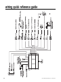
1
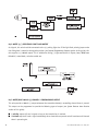
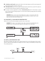
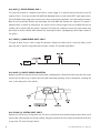
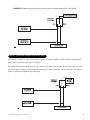
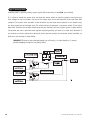
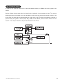
5000 ESP
Installation Guide
®
© 2000 Directed Electronics, Inc. Vista, CA N429 12-00
Rev. C 1.1
table of contents
Primary Harness (H1), 12-Pin Connector . . . . . 3
Primary Harness Wiring Diagram . . . . . . . . . 3
Primary Harness Wiring Guide . . . . . . . . . . . 3
Door Lock Harness (H2), 3-Pin Connector . . . . 8
Door Lock Wiring Guide. . . . . . . . . . . . . . . . . 8
Positive-Triggered, Relay Driven
Systems (Type A) . . . . . . . . . . . . . . . . . . . 8
Negative-Triggered, Relay Driven
Systems (Type B) . . . . . . . . . . . . . . . . . . . 9
Reversing Polarity (Type C) . . . . . . . . . . . . 10
After-market Actuators (Type D). . . . . . . . . 11
Electrically Activated Vacuum (Type E) . . . . 12
One-Wire System (Type F) . . . . . . . . . . . . . 12
Positive Multiplex (Type G) . . . . . . . . . . . . 13
Negative Multiplex (Type H) . . . . . . . . . . . 14
Plug-In Harnesses . . . . .
Super Bright LED . . .
Valet®/Program Switch
Programmer Interface
.
.
.
.
.
.
.
.
.
.
.
.
.
.
.
.
.
.
.
.
.
.
.
.
.
.
.
.
.
.
.
.
.
.
.
.
.
.
.
.
.
.
.
.
.
.
.
.
.
.
.
.
.
.
.
.
.
.
.
.
15
15
15
15
On-Board Dual Stage Shock Sensor . . . . . . . . 16
Optional Sensor Harness, 4-Pin Connector . . . 16
Internal Programming Jumper . . . . . . . . . . . 17
Light Flash Jumper . . . . . . . . . . . . . . . . . 17
To Access Another Feature In
The Same Menu . . . . . . . . . . . . . . . . . . . 19
To Select Another Menu . . . . . . . . . . . . . . 19
To Exit Learn Routine . . . . . . . . . . . . . . . 19
System Features Menus. . . . . . . . . . . . . . . . 20
Menu #1-Basic Features . . . . . . . . . . . . . . 20
Menu #2-Advanced Features . . . . . . . . . . . 20
Feature Descriptions . . . . . . . . . . . . . . . . . 21
Menu #1 - Basic Features . . . . . . . . . . . . . 21
Menu #2 - Advanced Features . . . . . . . . . . 22
Transmitter/Receiver Learn Routine . . . . . . . 24
To Exit Learn Routine . . . . . . . . . . . . . . . 25
Transmitter Configurations . . . . . . . . . . . . . . 26
Standard Configuration. . . . . . . . . . . . . . . 26
Expanded Configuration . . . . . . . . . . . . . . 26
Multi-Level Security Arming . . . . . . . . . . . . . 27
Table of Zones . . . . . . . . . . . . . . . . . . . . . . 27
Rapid Resume Logic . . . . . . . . . . . . . . . . . . 28
Long-Term Event History . . . . . . . . . . . . . . . 28
Optional Vehicle Recovery System . . . . . . . . 29
Nuisance Prevention Circuitry . . . . . . . . . . . . 30
Bypassing Sensor Inputs . . . . . . . . . . . . . . . 17
Troubleshooting. . . . . . . . . . . . . . . . . . . . . 30
System Features Learn Routine . . . . . . . . . . 18
Once a Feature is Programmed . . . . . . . . . . 19
Wiring Quick Reference Guide . . . . . . . . . . . 32
Version 1.3 or newer
of the Bitwriter®
chip is required to
program this unit.
Bitwriter™, Code Hopping™, DEI®, Doubleguard®, ESP™, FailSafe®, Ghost Switch™, Learn
Routine™, Nite-Lite®, Nuisance Prevention Circuitry®, NPC®, Revenger®, Silent Mode™, Soft Chirp®,
Stinger®, Valet®, Vehicle Recovery System®, VRS®, and Warn Away® are all Trademarks or Registered
Trademarks of Directed Electronics, Inc.
2
© 2000 Directed Electronics, Inc. Vista, CA
primary harness (H1), 12-pin connector
primary harness wiring diagram
H1/1
H1/2
H1/3
H1/4
H1/5
H1/6
H1/7
H1/8
______
______
______
______
______
______
______
______
ORANGE
(-) 500 mA ARMED OUTPUT
WHITE
WHITE/BLUE
(+)/(-) SELECTABLE LIGHT FLASH OUTPUT
(-) 200 mA CHANNEL 3 PROGRAMMABLE OUTPUT
BLACK/WHITE
GREEN
BLUE
(-) 200 mA DOMELIGHT SUPERVISION OUTPUT
(-) DOOR TRIGGER INPUT, ZONE 3
(-) INSTANT TRIGGER INPUT, ZONE 1
VIOLET
(+) DOOR TRIGGER INPUT, ZONE 3
BLACK
(-) CHASSIS GROUND INPUT
H1/9 ______
YELLOW
(+) SWITCHED IGNITION INPUT, ZONE 5
H1/10 ______
BROWN
(+) SIREN OUTPUT
H1/11 ______
RED
H1/12 ______
RED/WHITE
(+) CONSTANT POWER INPUT
(-) 200 mA CHANNEL 2 OUTPUT
primary harness wiring guide
This guide describes in detail the connection of each wire. Also included are possible applications of each wire.
This system was designed with the ultimate in flexibility and security in mind. Many of the wires have more than
one possible function. Please read the instructions carefully to ensure a thorough understanding of this unit and
how it operates.
H1/1 ORANGE (-) GROUND-WHEN-ARMED OUTPUT
This wire supplies a (-) ground as long as the system is armed. This output ceases as soon as the system is disarmed. The orange wire is pre-wired to control the p/n 8618 starter kill relay. It can supply up to 500 mA of
current.
NOTE: If connecting the orange wire to control another module, such as a p/n 529T or p/n 530T
window module, a 1 amp diode (type 1N4004) will be required. (See the following diagram.)
IMPORTANT! Never interrupt any wire other than the starter wire.
© 2000 Directed Electronics, Inc. Vista, CA
3
H1/2 WHITE (+/-) SELECTABLE LIGHT FLASH OUTPUT
As shipped, this wire should be connected to the (+) parking light wire. If the light flash polarity jumper under
the sliding door is moved to the opposite position (see Internal Programming Jumpers section of this guide), this
wire supplies a (-) 200 mA output. This is suitable for driving (-) light control wires in Toyota, Lexus, BMW, some
Mitsubishi, some Mazda, and other model cars.
H1/3 WHITE/BLUE 200 MA (-) CHANNEL 3 PROGRAMMABLE OUTPUT
This wire provides a 200 mA (-) output whenever the transmitter button(s) controlling channel three is pressed.
This output can be programmed to provide the following types of output (see System Features Learn Routine
section of this guide):
■ A validity output will send a signal as long as the transmission is received.
■ A latched output will send a signal continuously when channel three pressed and will continue until channel
three is pressed again.
4
© 2000 Directed Electronics, Inc. Vista, CA
■ A latched/reset with ignition output works similar to the latched output, but will also reset (output will
stop) when the ignition is turned on and then off.
■ A 30 second timed output will send a signal for 30 seconds when channel three is pressed. This output can
be shut off during the 30-second period by pressing Channel 3 again.
■ This output can also be programmed to provide a second unlock pulse when the disarm button is pressed
within 15 seconds after disarming the system. This can be used to unlock the passenger doors when installing
progressive door locks.
IMPORTANT! Never use this wire to drive anything but a relay or a low-current input! This
transistorized output can only supply 200 mA, and connecting directly to a solenoid, motor, or other
high-current device will cause the module to fail.
H1/4 BLACK/WHITE (-) 200 MA DOMELIGHT SUPERVISION OUTPUT
Connect this wire to the optional domelight supervision relay as shown below:
IMPORTANT! This output is only intended to drive a relay. It cannot be connected directly to the
domelight circuit, as the output cannot support the current draw of one or more bulbs.
H1/5 GREEN (-) DOOR TRIGGER INPUT, ZONE 3
Most vehicles use negative door trigger circuits. Connect the green wire to a wire showing ground when any door is
opened. In vehicles with factory delays on the domelight circuit, there is usually a wire unaffected by the delay circuitry.
This wire will report Zone 3.
© 2000 Directed Electronics, Inc. Vista, CA
5
H1/6 BLUE (-) INSTANT TRIGGER, ZONE 1
This input will respond to a negative input with an instant trigger. It is ideal for hood and trunk pins and will
report on Zone 1. It can also be used with 506T Glass Breakage Sensor, as well as other DEI® single stage sensors.
The H1/6 BLUE instant trigger wire can be used to shunt sensors during operation, using the auxiliary channels.
When any of the auxiliary channels are transmitted, the H1/6 BLUE wire monitors for a ground. If a ground is
detected within 5 seconds of transmission, the sensors and the instant trigger input on the BLUE wire will be
shunted until 5 seconds after the ground is removed. This allows the customer to access the trunk, remote start
the vehicle or roll the windows down without first disarming the alarm. (See Bypassing Sensor Inputs section of
this guide.)
H1/7 VIOLET (+) DOOR TRIGGER INPUT, ZONE 3
This type of dome circuit is used in many Ford products. Connect the violet wire to a wire that shows (+)12V
when any door is opened, and ground when the door is closed. This wire will report Zone 3.
H1/8 BLACK (-) CHASSIS GROUND CONNECTION
Remove any paint and connect this wire to bare metal, preferably with a factory bolt rather than your own screw.
(Screws tend to either strip or loosen with time.) We recommend grounding all your components, including the
siren, to the same point in the vehicle.
H1/9 YELLOW (+) IGNITION INPUT, ZONE 5
Connect this wire to the (+)12V ignition wire. This wire is pre-wired to the starter kill relay and must show (+)12V
with the key in Run position and during cranking. Take great care that this wire cannot be shorted to the chassis
at any point. This wire will report Zone 5.
6
© 2000 Directed Electronics, Inc. Vista, CA
H1/10 BROWN (+) SIREN OUTPUT
Connect this to the red wire of the Revenger® siren. Connect the black wire of the siren to (-) chassis ground,
preferably at the same point you connect the control module’s black ground wire.
H1/11 RED (+)12V CONSTANT POWER INPUT
Before connecting this wire, remove the supplied fuse. Connect to the battery positive terminal or the constant
12V supply to the ignition switch.
NOTE: Always use a fuse within 12 inches of the point you obtain (+)12V. Do not use the 15 fuse
in the harness for this purpose. This fuse protects the module itself.
H1/12 RED/WHITE 200 MA (-) CHANNEL 2 OUTPUT
When the system receives the code controlling channel 2 for longer than 1.5 seconds, the red/white will supply
an output as long as the transmission continues. This is often used to operate a trunk/hatch release or other
relay/driven function.
IMPORTANT! Never use this wire to drive anything but a relay or a low-current input! The transistorized output can only supply 200 mA of current. Connecting directly to a solenoid, motor, or other
high-current device will cause it to fail.
© 2000 Directed Electronics, Inc. Vista, CA
7
door lock harness (H2), 3-pin connector
H2/A
H2/B
H2/C
______
______
______
GREEN
(-) LOCK, (+) UNLOCK OUTPUT
EMPTY
UNLESS USING 451M
BLUE
(-) UNLOCK, (+) LOCK OUTPUT
This system can control two common power door lock types without any additional parts! With certain vehicles,
or if an actuator is to be installed, either a p/n 451M Door Lock Relay Satellite or two relays will be required.
IMPORTANT! If you mistake a Type C direct-wired system for a Type A positive-pulse system, the
module will be damaged!
door lock wiring guide
type A: (+) 12V pulses from the switch to the factory relays
The system can control a Type A system directly, with no additional parts. The switch will have three wires on
it, and one will test (+)12V constantly. The others will alternately pulse (+)12V when the switch is pressed to
the lock or unlock position.
If you cannot get to the switch, and you find a set of wires that pulse (+)12V alternately on lock and unlock,
you must take care to ensure that it is not a Type C direct-wire system.
Here is a test: Cut the wire which pulses (+)12V on lock, and then operate the switch to unlock. If all doors
unlock, the vehicle uses type A system. If you lose all door lock operation in both directions, you are operating
the master switch in a Type C system.
If you lose all door lock operation of one or more doors, but not all motors stop operating, and other doors still
work, you have cut a wire leading directly to one or more motors. You must instead find the actual wires leading
to the switch.
Many domestically-made GM vehicles use Type A locks. However, many more GM vehicles are Type C than in previous years. The full-size pickups (1989-up), many of the S10 Blazers, the Corvette, 1995 Cavalier/Sunfire 1993
- and newer, Camaro/Firebird all use Type C door locks, and cannot be controlled without a 451M! Almost all
domestically-built Fords are Type C. Ford builds very few Type A systems. Chrysler builds both Type A and Type
C, so use caution.
8
© 2000 Directed Electronics, Inc. Vista, CA
IMPORTANT! Remember that the functions of these wires are reversed between Type A and Type B!
type B: (-) pulses from the switch to the factory relays
This system is common in many Toyota, Nissan, Honda, and Saturn models, as well as Fords with the keylessentry system (some other Fords also use Type B).
The switch will have three wires on it, and one wire will test ground all the time. One wire will pulse (-) when
the switch locks the doors, and the other wire will pulse (-) when the switch unlocks the doors. This type of
system is difficult to mistake for any other type.
© 2000 Directed Electronics, Inc. Vista, CA
9
type C: reversing polarity
Interfacing with a reversing polarity system requires either two relays or one 451M (not included).
It is critical to identify the proper wires and locate the master switch to interface properly. Locate wires that
show voltage on lock and unlock. Cut one of the suspect wires and check operation of the locks from both
switches. If one switch loses operation in both directions and the other switch operates in one direction only,
you have located one of the target wires. The switch that lost all operation is the master switch. If one switch
works both directions and the other switch works only one direction, you have a Type A system. If both switches
still operate, but one or more doors have stopped responding entirely, you have cut a motor lead. Reconnect it
and continue to test for another wire. Once both wires have been located and the master switch identified, cut
both wires and interface as shown below.
IMPORTANT! If these are not connected properly, you will send (+) 12 volts directly to (-) ground,
possibly damaging the alarm or the factory switch.
10
© 2000 Directed Electronics, Inc. Vista, CA
type D: after-market actuators
In order for this system to control one or more after-market actuators, a 451M or two relays (optional) are
needed.
Vehicles without factory power door locks require the installation of one actuator per door. This requires
mounting the door lock actuator inside the door. Other vehicles may only require one actuator installed in the
driver's door if all door locks are operated when the driver's lock is used. This type of installation is required to
operate factory lock systems in Volvo (except 850), SAAB, and most Mazda, Isuzu and Subaru models. The fuse
used on 12-volt inputs should be 7.5A per motor installed in the vehicle.
© 2000 Directed Electronics, Inc. Vista, CA
11
type E: mercedes-benz and audi (1985 & newer)
Door locks are controlled by an electrically activated vacuum pump. Some Mercedes and Audi models use a Type
D system. Test by locking doors from the passenger key cylinder. If all the doors lock, the vehicle's door lock
system can be controlled with just two relays (optional). The control wire can be found in either kick panel and
will show (+)12V when doors are unlocked and (-) ground when doors are locked.
To interface, see diagram below. The system must be programmed for 3.5 second door lock pulses. (See
System Features Learn Routine section of this guide.)
type F: one-wire system
This system usually requires a negative pulse to unlock, and cutting the wire to lock the door. In some vehicles,
these are reversed. It is found in late-model Nissan Sentras, some Nissan 240SX, and Nissan 300ZX 1992 and later.
It is also found in some Mazda MPV's and some Mitsubishi's. One relay (optional) is used to interface to this type
of system as follows:
12
© 2000 Directed Electronics, Inc. Vista, CA
type G: positive multiplex
This system is most commonly found in Ford, Mazda, Chrysler and GM vehicles. The door lock switch or door key
cylinder may contain either one or two resistors. When interfacing with this type of door lock system, two relays
or a DEI 451M must be used. (See diagram below.)
single-resistor type
If one resistor is used in the door lock switch/key cylinder, the wire will pulse (+)12V in one direction and less
than (+)12V when operated in the opposite direction.
two-resistor type
If two resistors are used in the factory door lock switch/key cylinder, the switch/key cylinder will read less than
(+)12V in both directions.
determining the proper resistor values
To determine the resistor values, the door lock switch/key cylinder must be isolated from the factory door lock
system. For all testing, use a calibrated digital multimeter that is set to ohms.
1. Cut the output wire from the door lock switch/key cylinder in half.
2. Test with the meter from the switch side of the cut door lock switch/key cylinder wire to a reliable constant
(+)12V source. Some good constant (+)12V references are the power input source to the door lock switch/key
cylinder, the ignition switch power wire, or the (+) terminal of the battery.
3. Operate the door lock switch/key cylinder in both directions to determine the resistor values. If the multimeter displays zero resistance in one direction, no resistor is needed for that direction.
4. Once the resistor value(s) is determined, refer to the wiring diagram for proper wiring.
© 2000 Directed Electronics, Inc. Vista, CA
13
type H: negative multiplex
The system is most commonly found in Ford, Mazda, Chrysler and GM vehicles. The door lock switch or door key
cylinder may contain either one or two resistors. When interfacing with this type of door lock system, two relays
or a DEI 451M must be used. (See diagram below.)
single-resistor type
If one resistor is used in the door lock switch/key cylinder, the wire will pulse ground in one direction and resistance to ground when operated in the opposite direction.
two-resistor type
If two resistors are used in the factory door lock switch/key cylinder, the door lock switch/key cylinder will read
resistance to ground in both directions.
determining the proper resistor values
To determine the resistor values, the door lock switch/key cylinder must be isolated from the factory door lock
system. For all testing, use a calibrated digital multimeter that is set to ohms.
1. Cut the output wire from the door lock switch/key cylinder in half.
2. Test with the meter from the switch side of the cut door lock switch/key cylinder wire to a reliable ground
source. Some good ground references are the ground input source to the door lock switch/key cylinder or the
battery ground.
3. Operate the door lock switch/key cylinder in both directions to determine the resistor values. If the multimeter displays zero resistance in one direction, no resistor is needed for that direction.
4. Once the resistor value(s) is determined, refer to the wiring diagram for proper wiring.
14
© 2000 Directed Electronics, Inc. Vista, CA
plug-in harnesses
super bright LED, 2-pin white plug
The super bright LED operates at 2V DC. Make sure the LED wires are not shorted to ground as the LED will be
damaged. Multiple LED’s can be used, but they must be wired in series. The LED fits into a 9/32 inch mounting
hole. Be sure to check for clearance prior to drilling the mounting hole.
valet®/program switch, 2-pin blue plug
The Valet®/Program switch should be accessible from the driver’s seat. It plugs into the blue port on the side of
the unit. Since the system features Valet® by using the remote transmitter, the switch can be well hidden.
Consider how the switch will be used before choosing a mounting location. Check for rear clearance before drilling
a 9/32-inch hole and mounting the switch.The GRAY wire in the two-pin plug may also be used as a (+) ghost
switch input and can be connected to any (+) switch in the vehicle. (See Feature Descriptions section of this
guide.)
programmer interface, 3-pin black plug
The black three pin port is provided for personal computer programming of the unit. When using the DEI Bitwriter
(P/N 998T) or optional PC Interface Module (P/N 996T) it is possible to configure any and all of the programmable functions. The PC Interface Module works with an IBM compatible PC. (The 998T does not require the IBM
compatible PC.) For more information please refer to the guide packaged with the programmer. This port can also
be used to interface the Valet® Car★Com (DEI P/N 820T) with the security system.
© 2000 Directed Electronics, Inc. Vista, CA
15
on-board dual stage shock sensor
There is a dual-stage shock sensor inside the control unit. Adjustments are made via the rotary control as indicated in the diagram. Since the shock sensor does not work well when mounted firmly to metal, we do not
recommend screwing down the control module. The full trigger of the on-board shock sensor reports Zone 2. See
the Table of Zones section of this guide.
NOTE: When adjusting the sensor, it must be in the same mounting location that it will be after
the installation is completed. Adjusting the sensor and then relocating the module requires readjustment.
optional sensor harness, 4-pin connector
The four-pin sensor harness is optional, and is not included with this unit.
RED, BLACK
These wires supply constant 12 volts and ground to the optional sensor.
BLUE, GREEN
These wires are multiplex inputs. If a (-) input of less than 0.8 seconds is supplied to either wire, the Warn-Away
response will occur. A (-) input of longer than 0.8 seconds to either wire will initiate the triggered sequence and
report Zone 4.
16
© 2000 Directed Electronics, Inc. Vista, CA
internal programming jumper
light flash jumper
This jumper is used to determine the light flash output. In the (+) position, the on-board relay is enabled and
the unit will output (+)12V on the WHITE wire, H1/2. In the (-) position, the on-board relay is disabled. The
WHITE wire, H1/2, will supply a 200 mA (-) output suitable for driving factory parking light relays.
bypassing sensor inputs
There are times when you need to temporarily bypass all sensor inputs to the unit, such as when remote starting the vehicle. Anytime an auxiliary channel output is used, all inputs are bypassed for 5 seconds. During the
5 second bypass period, ground can be supplied to the H1/6 Blue wire without triggering the unit. When the 5
second bypass period ends, if the unit sees ground on the H1/6 Blue wire, all trigger inputs except the door
trigger input will remain bypassed until 5 seconds after ground is removed from the BLUE wire. This can be done
using the status output of a 551T remote start unit as shown below:
© 2000 Directed Electronics, Inc. Vista, CA
17
™
system features learn routine
The System Features Learn Routine™ dictates how the unit operates. Due to the number of steps, they have been
broken up into two menus. It is possible to access and change any of the feature settings using the
Valet®/Program switch. However, this process can be greatly simplified by using the optional DEI Bitwriter or
Personal Computer Interface, P/N 996T. Any of the settings can be changed and then assigned to a particular
transmitter, up to four, a feature called Owner Recognition. Each time that particular transmitter is used to
disarm the system, the assigned feature settings will be recalled. Owner Recognition is only possible when programming the unit via the 996T or the 998T DEI Bitwriter.
Using the optional DEI Bitwriter or PC Interface, the learn routine may be locked. Make sure the learn
routine is unlocked before programming features. If the siren generates one long chirp when attempting
to program the unit, the learn routine is locked and must be unlocked using the DEI Bitwriter or PC before proceeding.
1.
Open a door.(The H1/5 GREEN wire or the H1/7 VIOLET wire must be connected.)
2.
Ignition. Turn the ignition on, then back off: (The H1/9 YELLOW wire must be connected.)
3.
Select a Menu. Press and HOLD the Valet®/Program button: (The Valet®/Program button
must be plugged into the blue port.) After three seconds the siren will chirp once indicating entry to the Basic Features Menu #1. If this is the menu you wish to access, release
the button and go on to step 4. If the button is not released, you will jump to the
Advanced Features Menu #2 and the siren will chirp twice. Once you have selected the
desired menu, release the Valet®/Program button and then go to step four.
4.
Select a Feature. Press and release the Valet®/Program button the number of times corresponding to the step you wish to change. For example, to access the third feature, press
and release three times. Then press the button once more and HOLD it. The siren will chirp
the number of times equal to the step you have accessed.
5.
Program the Feature. While HOLDING the Valet®/Program button, you can toggle the
feature on and off using the remote transmitter. Pressing Button I will select the one chirp
or default setting. Pressing Button II will select the two chirp setting. (See
Transmitter/Receiver Learn Routine section of this guide.)
NOTE: The Valet® pulse count feature (2-5) and the Channel three timed output (2-9) have five
possible settings each. Pressing channel 2 will toggle through all the possible settings.
18
© 2000 Directed Electronics, Inc. Vista, CA
6.
Release the Valet®/Program button.
once a feature is programmed
■
Other features can be programmed within the same menu.
■
Another menu can be selected.
■
The learn routine can be exited if programming is complete.
to access another feature in the same menu
1. Press and release the Valet®/Program switch the number of times necessary to advance from the feature you
just programmed to the next one you want to program.
2. Then press the Valet®/Program switch once more and HOLD it.
For example, if you just programmed the third feature in the menu and you would like to program the seventh
feature in the menu, you would press and release the Valet®/Program switch four times and then press it once
more and HOLD it. The siren would chirp seven times to confirm access to the seventh feature.
to select another menu
1. Press and HOLD the Valet®/Program switch.
2. After three seconds, the unit will advance to the next menu and the siren will chirp, indicating which menu
has been accessed.
For instance, if you just programmed some features in Menu #1 (Basic Features) and you desire to program a
feature in Menu #2, you press and HOLD the Valet®/Program button. After three seconds, the siren chirps twice
indicating access to Menu #2.
to exit the learn routine
To exit the learn routine, do one of the following:
1. Close the open door.
2. Turn the ignition on.
3. No activity for longer than 15 seconds.
4. Press the Valet®/Program switch too many times.
© 2000 Directed Electronics, Inc. Vista, CA
19
system features menus
Items in bold text have been programmed to the two chirps setting at the factory.
menu #1 - basic features
FEATURE NUMBER
ONE-CHIRP SETTING (DEFAULT)
TWO-CHIRP SETTING
1-1
Active arming
Passive arming
1-2
Chirps on
Chirps off
1-3
Ignition-controlled door locks on
Ignition-controlled door locks off
1-4
Active locking only
Passive locking
1-5
Panic with ignition on
No panic with ignition on
1-6
0.8 second door lock pulses
3.5 second door lock pulses
1-7
Forced passive arming on
Forced passive arming off
1-8
Automatic engine disable on
Automatic engine disable off
1-9
Armed When Driving (AWD)
Vehicle Recovery System (VRS®)
1-10
Code Hopping™ On
Code Hopping™ off
menu #2 - advanced features
FEATURE NUMBER
20
ONE-CHIRP SETTING (DEFAULT)
TWO-CHIRP SETTING
2-1
Siren
Horn honk
2-2
30-second siren duration
60-second siren duration
2-3
Nuisance Prevention Circuitry™ ON
Nuisance Prevention Circuitry™ OFF
2-4
Progressive door trigger
Instant door trigger
2-5
Valet switch input: 1 pulse
Valet switch input: 2-5 pulses
2-6
Door trigger error chirp ON
Door trigger error chirp OFF
2-7
Ignition-controlled domelight ON
Ignition-controlled domelight OFF
2-8
Single unlock pulse
Double unlock pulse
2-9
Channel 3: Validity
Channel 3: latched/latched, reset
with ignition/30-second timed/
second unlock output
© 2000 Directed Electronics, Inc. Vista, CA
feature descriptions
The features of the system are described below. Features that have additional settings that can be selected only
when programming with the PC interface or Bitwriter are indicated by the following icon:
menu #1 - basic features
1-1 ACTIVE/PASSIVE ARMING: When active arming is selected, the system will only arm when the transmitter is
used. When set to passive, the system will arm automatically 30 seconds after the last door is closed. To alert
the consumer of passive arming, the siren will chirp 20 seconds after the door is closed. This provides the consumer with an audible warning prior to the system actually arming. At the 30 second mark, the system will arm
but the siren will not chirp.
1-2 Chirps ON/OFF: This feature controls the chirps or voice messages (if using the 516M voice module) that
confirm the arming and disarming of the system.
1-3 IGNITION CONTROLLED DOOR LOCKS ON/OFF: When turned on, the doors will lock three seconds after the
ignition is turned on and unlock when the ignition is turned off. The TechSoft Programmer or the 998T Bitwriter™
will display separate steps for ignition lock and ignition unlock. They can be programmed on or off independently.
1-4 ACTIVE/PASSIVE LOCKING: If passive arming is selected in step 1-1, then the system can be programmed
to either lock the doors when passive arming occurs, or only lock the doors when the system is armed via the
transmitter. Active locking means the system will not lock the doors when it passively arms. Passive locking means
that the system will lock the doors when it passively arms.
NOTE: Remember, when passive arming is selected, the unit will chirp 20 seconds after the last door is
closed. The system does not actually arm or lock the doors until 30 seconds after the door has been closed.
1-5 PANIC WITH IGNITION ON: This step controls whether or not the Panic Mode is available with the ignition
on. In some states, there are laws prohibiting a siren from sounding in a moving vehicle. This feature makes the
system compliant with these regulations.
1-6 DOOR LOCK PULSE DURATION: Some European vehicles, such as Mercedes-Benz and Audi, require longer lock
and unlock pulses to operate the vacuum pump. Programming the system to provide 3.5 second pulses, will
accommodate the door lock interface in these vehicles. The default setting is 0.8 second door lock pulses.
1-7 FORCED PASSIVE ARMING ON/OFF: To use this feature, passive arming must be selected in step 1-1. When
turned on, forced passive arming will ensure that the system will passively arm, even if a zone is left open or
invalid. Forced passive arming occurs one hour after the ignition is turned off.
© 2000 Directed Electronics, Inc. Vista, CA
21
1-8 AUTOMATIC ENGINE DISABLE (AED) ON/OFF: AED is a full-time, passive starter disable that works
independently of the security system. When turned on, the orange, ground-when-armed output (H1/1) will go
active 30 seconds after the ignition is turned off. The LED will flash at half its normal rate when the ignition is
turned off to indicate that AED is active and will interrupt the starter in 30 seconds. AED does not occur in Valet®
mode and can be bypassed using the emergency override procedure. The transmitter can be used to disarm AED;
however, the system must be armed and then disarmed with the transmitter, in order to disarm AED.
1-9 ARMED WHILE DRIVING/VEHICLE RECOVERY SYSTEM: In the default setting (Armed While Driving), the
system can be armed with the ignition on. When armed, the ground-when-armed is not active and the sensors
are bypassed. The door triggers will remain active. If programmed to the Vehicle Recovery System (VRS®) setting,
VRS will be activated.
1-10 CODE-HOPPING™ ON/OFF: The system uses a mathematical formula to change its code each time the transmitter and receiver communicate. This makes the group of bits or “word” from the transmitter very long. The
longer the word is, the easier it is to block its transmission to the unit. Disabling the Code-Hopping™ feature lets
the receiver ignore the Code-Hopping™ part of the transmitted word. As a result, the unit may have better range
with Code-Hopping™ off.
menu #2 - advanced features
2-1 SIREN/HORN HONK: The system can be programmed to output pulses instead of a continuous output when
the system is triggered. This is useful to honk the factory horn in applications where a siren is undesirable.
Remember that the unit is only capable of supplying 1 amp of current. A relay will be required to interface with
most factory horn systems.
2-2 SIREN DURATION 30/60 SECONDS: It is possible to program the unit to sound for 30 or 60 seconds
during the triggered sequence. Some states have laws regulating how long a security system can sound.
When using the TechSoft Programmer or Bitwriter™, the siren can be programmed to sound for any length of time
ranging from 1 to 180 seconds. Use the right and left arrows or the + and - keys on your keyboard to change the
siren duration in 1 second intervals. Holding down the key will rapidly increase or decrease the setting. The
desired siren duration can also be directly entered by using the number keys on your computer's keyboard. When
using the Bitwriter, pressing the SELECT button will adjust the siren duration.
2-3 NUISANCE PREVENTION® CIRCUITRY (NPC™) ON/OFF: NPC™ stops repeated triggering of the same zone. If
one zone is triggered three times in one hour, that zone is bypassed for one hour, starting from the time of the
third trigger. During that hour, if the system detects a trigger on that zone again, the system resets the one hour
timer. If one hour passes and the zone has not triggered again, the zone is activated and can trigger the system
again. NPC™ only monitors sensor inputs, and does not bypass the door trigger or the ignition trigger at any time.
If NPC™ is turned off, the system will respond to repeated triggers on the sensor inputs and will do so indefinitely. Some states have laws regulating how many times a security system can trigger before it is considered a
nuisance and the vehicle is towed away.
22
© 2000 Directed Electronics, Inc. Vista, CA
2-4 PROGRESSIVE DOOR TRIGGER ON/OFF: The system responds to a door trigger input with a progressive
response. When the door is opened with the system armed, the siren will chirp 10 times prior to the full triggered sequence. The door trigger is still treated as an instant trigger and closing the door quickly will not prevent
a full triggered sequence from occurring. If the progressive door trigger is programmed off, the full siren output
will occur the moment the door is opened.
2-5 VALET PULSE COUNT 1 to 5 PULSES: The system can be programmed to count the number presses of the
valet switch before disarming the security system or VRS®. The factory default setting is one pulse. The unit can
be set for 2 to 5 pulses using the two-chirp setting to select the pulse count.
GHOST SWITCH OPTION: For added security, the GRAY wire on the two-pin Valet®/Program can be
connected to any switch in the vehicle that provides a positive (+) momentary pulse.
2-6 DOOR TRIGGER ERROR CHIRP ON/OFF: With the door trigger error chirp programmed off, the system will not
report an invalid zone on arming when the door trigger wire is active. This eliminates the extra chirps that occur
when interfacing with vehicles that have exceptionally long dome light delay circuits.
2-7 IGNITION-CONTROLLED DOMELIGHT SUPERVISION ON/OFF: If turned on, the system will turn on the domelight for 30 seconds when the ignition is turned off. The optional domelight supervision feature must be installed.
2-8 DOUBLE PULSE UNLOCK ON/OFF: Some vehicles require two pulses on a single wire to unlock the doors.
When the double pulse unlock feature is turned on, the BLUE H2/C wire will supply two negative pulses instead
of a single pulse. At the same time, the GREEN H2/A wire will supply two positive pulses instead of a single pulse.
This makes it possible to directly interface with double pulse vehicles without any extra parts.
2-9 CHANNEL 3 VALIDITY/LATCHED/LATCHED RESET WITH IGNITION/30 SECOND TIMED/SECOND UNLOCK
OUTPUT: Channel 3 can be programmed for these output configurations. The unit is set to the default validity
output. To change the configuration, use the two-chirp setting to toggle to the different configurations.
© 2000 Directed Electronics, Inc. Vista, CA
23
transmitter/receiver learn routine™
The system comes with two transmitters that have been taught to the receiver. The receiver can store up to four
different transmitter codes in memory. Use the following learn routine to add transmitters to the system or to
change button assignments if desired.
When the learn routine has previously been programmed using an optional hand-held system programmer
(p/n 998T) or PC Interface module, it may have been locked. Before proceeding with reprogramming the
learn routine, it must be unlocked by using either p/n 998T or the PC Interface module - this cannot be done
manually with the Valet switch. If the learn routine is locked, transmitters cannot be programmed to the system.
1.
Open a door. (The H1/5 GREEN wire or the H1/7 VIOLET wire must be connected.)
2.
Key. Turn the ignition on. (The YELLOW wire, H1/9 must be connected.)
3.
Select the receiver channel: Press and release the Valet®/Program button the number of
times necessary to access the desired channel.
NOTE: If adding a remote, a button must be taught to the unit in the Channel 1 or Channel 4 position prior to programming other channels, unless programming to one of the Auto Learn
Configurations.
Press and HOLD the Valet®/Program button once more. The siren will chirp and the LED will blink the number of
times corresponding to the channel that is accessed.
CHANNEL NUMBER
FUNCTION
WIRE COLOR
1
Arm/Disarm/Panic
2
Silent Mode™/Remote Valet®/Trunk Release
RED/WHITE
3
Remote Start or other accessories
WHITE/BLUE
4
Arm only
5
Disarm only
6
Panic only
7
Auto Learn Expanded Configuration* (only with optional 4-button transmitter)
8
Auto Learn Standard Single Button Arm/Disarm Configuration*
9
Delete all transmitters
*NOTE: For Auto Learn Configurations, see Transmitter Configurations section of this guide.
24
© 2000 Directed Electronics, Inc. Vista, CA
4.
Press the transmitter button: While HOLDING the Valet®/Program switch, press the
button from the transmitter that you wish to assign to the selected channel. The unit will
chirp indicating successful programming. It is not possible to teach a transmitter button
to the system more than once.
Channels #4-6: Channels 4 through 6 are used to assign the arm, disarm and panic functions to separate buttons
on the remote control. Teaching a button to Channel 4 erases all information about that remote from memory.
Any auxiliary functions that are desired will have to be reprogrammed. Similarly, if the remote is set up to use
the separate arm, disarm and panic channels and a button from that remote is entered into channel one, the
remote will be erased from memory, and the system will only recognize the button that was entered into channel
one.
Channel #9: If any transmitter button from a known transmitter is programmed to Channel 9, all transmitters
will be erased from memory and will revert to the default feature settings (see the Features Menu section of this
guide). This is useful in cases where the one of the customer's transmitters is lost or stolen. This will erase any
lost or stolen transmitters from the system's memory. It can also be used to start from scratch if the transmitter
buttons were programmed incorrectly.
®
5. Release: Once the code is learned, the Valet /Program button can be released.
to exit learn routine
Learn Routine™ will be exited if:
■ Ignition is turned off.
■ Door is closed.
■ Valet®/Program button is pressed too many times.
■ More than 15 seconds elapse between steps.
One long chirp indicates that Learn Routine™ has been exited.
© 2000 Directed Electronics, Inc. Vista, CA
25
transmitter configurations
Using the Auto Learn functions in the Transmitter/Receiver Learn Routine, the transmitters can be programmed
either with the standard single button arm/disarm configuration (default) or with the expanded configuration,
which requires an optional 4-button transmitter.
standard single button arm/disarm configuration
When programmed for standard single button arm/disarm configuration, the transmitter buttons are assigned to
the following functions:
. . . . . . . . . . operates . . . . . . . . . . Arm/Disarm/Panic
. . . . . . . . . . operates . . . . . . . . . . Channel 2
and
. . . operates . . . . . . . . . . Channel 3
expanded configuration
Your system has an expanded configuration that can be fully utilized when upgrading to the optional four-button
remote. In the expanded configuration, your system will operate similarly to many factory keyless entry systems
that use separate remote transmitter buttons for the arm, disarm, panic and auxiliary output functions:
. . . . . . . . . . . operates . . . . . . . . . . . Arm only
. . . . . . . . . . . operates . . . . . . . . . . . Disarm only
. . . . . . . . . . . operates . . . . . . . . . . . Channel 2
. . . . . . . . . . . operates . . . . . . . . . . . Panic
and
. . operate . . . . . . . . . . . . Channel 3
The Expanded Configuration also allows the user to utilize Multi-Level Security Arming (described in the following section).
NOTE: If a 2-button transmitter is programmed with the expanded configuration, the Panic feature
and Channel 2 output can no longer be controlled by the transmitter.
26
© 2000 Directed Electronics, Inc. Vista, CA
multi-level security arming
Multi-Level Security Arming is a feature that allows you to select which of the security system's inputs or sensors
will be active and which will be bypassed at the time that the system is armed. (See Table of Zones section in
this guide.) Pressing the arm button (only on a Expanded Configuration transmitter) again within five seconds
of arming the security system will activate the Multi-Level Security Arming feature. Each time the arm button is
pressed again, a different security level is selected. The different security levels can be selected as follows:
■ Pressing the arm button once: The siren chirps once. The system is armed.
■ Pressing the arm button twice within five seconds: The siren chirps twice followed by a long chirp. Zone Two is
now bypassed.
■ Pressing the arm button a third time within five seconds: The siren chirps three times followed by a long
chirp. Zone Four is now bypassed.
■ Pressing the arm button a fourth time within five seconds: The siren chirps four times followed by a long
chirp. Zones Two and Four are now bypassed.
■ Pressing the arm button a fifth time within five seconds: The siren chirps five times followed by a long chirp.
All input zones, except the ignition, are now bypassed.
NOTE: Multi-Level Security Arming only applies to a single arming cycle. Once the system is disarmed
and then re-armed, all the zones will be active again.
table of zones
When using the diagnostic functions, use the Table of Zones to see which input has triggered the system. It is
also helpful in deciding which input to use when connecting optional sensors and switches.
ZONE NO.
TRIGGER TYPE
INPUT DESCRIPTION
1
Instant
H1/6 BLUE wire. Connect to optional hood/trunk pins.
2
On-board shock sensor
Heavy impact detected by the on-board shock sensor.
3
Two-stage, progresses from
warning to full alarm
Door switch circuit. H1/5 GREEN or H1/7 VIOLET.
4
Multiplexed Input
BLUE and GREEN wires of optional sensor plug. Inputs
shorter than 0.8 seconds will trigger a Warn Away response,
while inputs longer than 0.8 seconds will instantly trigger
a full alarm sequence and report Zone 4.
5
Two-stage (similar to doors)
Ignition input. H1/9 YELLOW.
NOTE: The Warn Away® response does not report on the LED.
© 2000 Directed Electronics, Inc. Vista, CA
27
rapid resume logic
The Rapid Resume Logic feature ensures that when the security system is powered back up after power has been
disconnected, the system will resume the same state it was in before power was lost. For example, if power is
disconnected during a full trigger sequence, the system will still be in the full trigger sequence when power is
reconnected to the unit. If power is disconnected while the unit is disarmed, it will still be disarmed when power
is restored. This also applies to the VRS sequence. If the unit loses power at any time during the VRS sequence,
it will automatically resume the VRS full trigger sequence when the unit is powered back up.
long term event history
The system stores the last two full triggers in memory. These are not erasable. Each time the unit sees a full
trigger, the older of the two triggers in memory will be replaced by the new trigger. To access long term event
history:
1.
With the ignition off, press and HOLD the Valet®/Program switch.
2.
Turn on the ignition.
3.
Release the Valet®/Program switch.
4.
Press and release the Valet®/Program switch within 5 seconds. The LED will flash in groups
indicating the last two zones that triggered the unit. The LED will flash for one minute or
until the ignition is turned off.
NOTE: The Warn Away® triggers are not stored to memory and will not be reported.
28
© 2000 Directed Electronics, Inc. Vista, CA
®
optional vehicle recovery system (VRS )
No additional parts are required to add the optional VRS® feature. However for the VRS® feature to be effective,
the 8618 Starter Kill Relay must be installed. The VRS® feature can be activated with the remote transmitter and
deactivated with the valet switch. If the VRS® option is selected it is recommended to program the Valet switch
to respond to more than one pulse for maximum security. (See System Features Learn Routine section.)
to arm the VRS
1.
Turn the ignition to the ON position.
2.
Press
on the transmitter for 1 second.
The parking light will flash once and the siren will chirp once to confirm that the VRS system is armed and will
enter the trigger sequence next time a door is opened and then closed.
to disarm the VRS
To disarm VRS (before siren begins chirping):
1.
2.
Turn the ignition to the ON position.
Press
on the transmitter for 1 second.
The parking lights will flash twice and the siren will chirp twice to confirm that the VRS® system is disarmed.
To disarm VRS (after the siren has begun chirping):
1.
Turn the ignition to the ON position.
2.
Press and release the Valet®/Program switch the selected number of times programmed in
Step 2-5. (See System Features Learn Routine section of this guide.)
NOTE: For a detailed explanation to the VRS triggered sequence, refer to the Vehicle Recovery
System section of the Owner's Guide.
© 2000 Directed Electronics, Inc. Vista, CA
29
™
nuisance prevention circuitry
NPC™ requires that you change the way you test the system as NPC™ will bypass an input zone for 60 minutes.
If the system “sees” the same zone trigger three times AND the triggers are spaced less than an hour apart, the
system will bypass that input zone for 60 minutes. If that zone does not attempt to trigger the system during
the 60-minute bypass period, the zone’s monitoring will begin again at the end of the hour. If it does attempt
to trigger while bypassed, the 60-minute bypass starts over again.
Disarming and rearming the system does not reset NPC™. The only way to reset NPC™ is for the 60 minutes to
pass, without a trigger, or for the ignition to be turned on. This allows the system to be repeatedly triggered,
disarmed and rearmed, and still allow NPC™ to bypass a faulty zone.
When disarming the system, 5 chirps indicate NPC is activated. The LED will report the zone that has been
bypassed. (See Diagnostics section of this guide.)
troubleshooting
■ Starter kill does not work:
Is the correct starter wire being interrupted? If the car starts when the starter kill relay is completely disconnected, the wrong starter wire has been cut and interrupted.
Yellow wire is not connected to true ignition. It is connected to an accessory circuit.
■ Shock sensor does not trigger the alarm:
Has the NPC™ system been triggered? If so, you will hear five chirps when disarming. To check this, turn the
ignition key on and off to clear the NPC™ from memory, and then retest the shock sensor. For a detailed description of NPC™, see Owner’s Guide.
■ Door input does not immediately trigger full alarm. Instead, I hear chirps for the first three seconds:
That’s how the progressive two-stage door input works! This is the instant response feature of this system. Even
if the door is closed immediately, the system provides an instant trigger by chirping, and then progressing to a
constant siren.
■ Closing the door triggers the system, but opening the door does not:
Have you correctly identified the type of door switch system? This happens often when the wrong door input has
been used.
30
© 2000 Directed Electronics, Inc. Vista, CA
■ System will not passively arm until it is remotely armed and then disarmed:
Are the door inputs connected? Is a blue wire connected to the door trigger wire in the vehicle? Either the green
H1/5 or the violet H1/7 should be used instead.
■ Door input does not respond with the progressive trigger, but with immediate full alarm:
What zone does the LED indicate? If the LED indicates that the impact sensor caused the trigger, the sensor may
be detecting the door opening. Reducing the sensitivity or relocating the sensor can often solve this problem.
If the LED indicates that the door caused the trigger, you may have programmed the progressive door trigger off.
(See Feature 2-4 in the Feature Descriptions section of this guide.)
■ The Valet® switch does not work:
Is it plugged into the correct socket?
Check the System Features Learn Routine for the programmed Valet pulse count.
■ Status LED does not work:
Make sure that it is plugged in. (See Plug-In Harnesses section of this guide.) Is the LED plugged into the correct
socket?
© 2000 Directed Electronics, Inc. Vista, CA
31
wiring quick reference guide
32
© 2000 Directed Electronics, Inc. Vista, CA