1
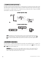
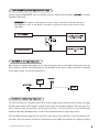
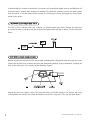
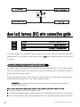
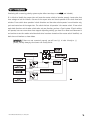
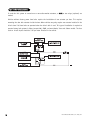
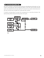
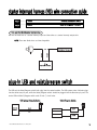
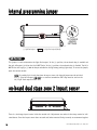
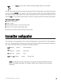
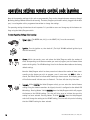
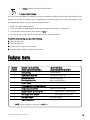
Model 740T
Installation Guide
© 2004 Directed Electronics, Inc. Vista, CA N740T 09-04
table of contents
what is included . . . . . . . . . . . . . . . . . . . . . . . . . . . . . . . . . . . . . . . . . . . . . . . . . . . . . . . . . . . . . . . . 3
primary harness (H1) wire connection guide . . . . . . . . . . . . . . . . . . . . . . . . . . . . . . . . . . . . . . . . . . . . . 3
door lock harness (H2) wire connection guide . . . . . . . . . . . . . . . . . . . . . . . . . . . . . . . . . . . . . . . . . . . . 8
type A: positive (+) 12V pulses from the switch to the factory relays. . . . . . . . . . . . . . . . . . . . . . . . . . 8
type B: negative (-) pulses from the switch to the factory relays. . . . . . . . . . . . . . . . . . . . . . . . . . . . 10
type C: reversing polarity . . . . . . . . . . . . . . . . . . . . . . . . . . . . . . . . . . . . . . . . . . . . . . . . . . . . . . . 11
type D: after-market actuators . . . . . . . . . . . . . . . . . . . . . . . . . . . . . . . . . . . . . . . . . . . . . . . . . . . 12
type E: mercedes-benz and audi (1985 and newer) . . . . . . . . . . . . . . . . . . . . . . . . . . . . . . . . . . . . . 13
type F: one-wire system. . . . . . . . . . . . . . . . . . . . . . . . . . . . . . . . . . . . . . . . . . . . . . . . . . . . . . . . 14
type G: positive (+) multiplex. . . . . . . . . . . . . . . . . . . . . . . . . . . . . . . . . . . . . . . . . . . . . . . . . . . . 14
type H: negative (-) multiplex . . . . . . . . . . . . . . . . . . . . . . . . . . . . . . . . . . . . . . . . . . . . . . . . . . . 16
starter interrupt harness (H3) wire connection guide . . . . . . . . . . . . . . . . . . . . . . . . . . . . . . . . . . . . . . 17
plug-in LED and valet/program switch . . . . . . . . . . . . . . . . . . . . . . . . . . . . . . . . . . . . . . . . . . . . . . . . . 17
internal programming jumper . . . . . . . . . . . . . . . . . . . . . . . . . . . . . . . . . . . . . . . . . . . . . . . . . . . . . . . 18
light flash jumper . . . . . . . . . . . . . . . . . . . . . . . . . . . . . . . . . . . . . . . . . . . . . . . . . . . . . . . . . . . . 18
on-board dual stage zone 2 impact sensor . . . . . . . . . . . . . . . . . . . . . . . . . . . . . . . . . . . . . . . . . . . . . . 18
bypassing sensor inputs . . . . . . . . . . . . . . . . . . . . . . . . . . . . . . . . . . . . . . . . . . . . . . . . . . . . . . . . . . 19
transmitter/receiver remote control code learning . . . . . . . . . . . . . . . . . . . . . . . . . . . . . . . . . . . . . . . . 19
transmitter configuration . . . . . . . . . . . . . . . . . . . . . . . . . . . . . . . . . . . . . . . . . . . . . . . . . . . . . . . . . 21
operating settings remote control code learning . . . . . . . . . . . . . . . . . . . . . . . . . . . . . . . . . . . . . . . . . . 22
features menu . . . . . . . . . . . . . . . . . . . . . . . . . . . . . . . . . . . . . . . . . . . . . . . . . . . . . . . . . . . . . . . . . 23
feature descriptions . . . . . . . . . . . . . . . . . . . . . . . . . . . . . . . . . . . . . . . . . . . . . . . . . . . . . . . . . . . . . 24
nuisance prevention circuitry™ . . . . . . . . . . . . . . . . . . . . . . . . . . . . . . . . . . . . . . . . . . . . . . . . . . . . . 25
table of zones . . . . . . . . . . . . . . . . . . . . . . . . . . . . . . . . . . . . . . . . . . . . . . . . . . . . . . . . . . . . . . . . . 26
troubleshooting . . . . . . . . . . . . . . . . . . . . . . . . . . . . . . . . . . . . . . . . . . . . . . . . . . . . . . . . . . . . . . . . 26
wiring quick reference guide . . . . . . . . . . . . . . . . . . . . . . . . . . . . . . . . . . . . . . . . . . . . . . . . . . . . . . . 29
Hornet®, Bitwriter™, Stealth Coding Technology™, Doubleguard®, ESP™, FailSafe®, Ghost Switch™,
Learn Routine™, Nite-Lite®, Nuisance Prevention Circuitry®, NPC®, Revenger®, Silent Mode™, Soft
Chirp®, Stinger®, Valet®, Vehicle Recovery System®, VRS®, and Warn Away® are all Trademarks or
Registered Trademarks of Directed Electronics, Inc.
2
© 2004 Directed Electronics, Inc. Vista, CA
what is included
■ The control module
■ A high-powered siren
■ Two 3-button remote transmitters
■ The 12-pin primary harness
■ The plug-in LED system status indicator
■ The 3-pin door lock harness
■ The plug-in Valet/Program switch
■ The plug-in starter interrupt harness
■ An on-board zone 2 impact sensor
primary harness (H1) wire connection guide
H1/1
H1/2
H1/3
H1/4
H1/5
H1/6
H1/7
______
______
______
______
______
______
______
ORANGE
(-) 500 mA GROUND-WHEN-ARMED OUTPUT
WHITE
(+/-) SELECTABLE LIGHT FLASH OUTPUT
WHITE/BLUE
BLACK/WHITE
(-) 200 mA CHANNEL 3 VALIDITY OUTPUT
(-) 200 mA INTERIOR LIGHT ILLUMINATION OUTPUT
GREEN
BLUE
(-) DOOR TRIGGER INPUT, ZONE 3
(-) MULTIPLEX TRIGGER INPUT, ZONE 1
VIOLET
(+) DOOR TRIGGER INPUT, ZONE 3
H1/8 ______
BLACK
(-) CHASSIS GROUND INPUT
H1/9 ______
YELLOW
(+) IGNITION INPUT, ZONE 5
H1/10 ______
BROWN
(+) SIREN OUTPUT
H1/11 ______
RED
H1/12 ______
RED/WHITE
(+)12V CONSTANT POWER INPUT
(-) 200 mA CHANNEL 2 VALIDITY OUTPUT
H1/1 ORANGE (-) ground-when-armed 500 mA output
This wire supplies (-) ground as long as the system is armed. This output ceases as soon as the system is disarmed.
It can be used to turn on an optional sensor or to control an optional accessory, such as a window module or
pager.
© 2004 Directed Electronics, Inc. Vista, CA
3
H1/2 WHITE (+/-) selectable light flash output
As shipped, this wire should be connected to the (+) parking light wire. If the light flash polarity jumper inside
the control module is moved to the opposite position (see Internal Programming Jumper section of this guide),
this wire supplies a (-) 200 mA output. This is suitable for driving (-) light control wires in Toyota, Lexus, BMW,
some Mitsubishi, some Mazda, and other model cars.
(+) Positive Light Flash Output
(-) Negative Light Flash Output
NOTE: For parking light circuits that draw 10 amps or more, the internal jumper must be switched
to a (-) light flash output. (See the Internal Programming Jumper section of this guide.) P/N
8617 or a standard automotive SPDT relay must be used on the H1/2 light flash output harness
wire.
H1/3 WHITE/BLUE (-) channel 3 output
This wire provides a (-) 200 mA output whenever the transmitter code controlling Channel 3 is received. This
output will continue as long as that transmission is received. Use for options such as 551T Valet® Start system,
529T or 530T power window controllers, etc.
IMPORTANT! Never use this wire to drive anything except a relay or a low-current input! The
transistorized output can only provide 200 mA of current, and connecting directly to a solenoid,
motor, or other high-current device will cause it to fail.
4
© 2004 Directed Electronics, Inc. Vista, CA
H1/4 BLACK/WHITE (-) interior light illumination output
Connect the H1/4 BLACK/WHITE wire to an optional relay for interior light illumination (pp/n 8617 or standard
automotive SPDT relay).
IMPORTANT! This output is only intended to drive a relay. It cannot be connected directly to
the domelight circuit, as the output is not able to support the current draw of one or more
light bulbs.
H1/5 GREEN (-) door trigger input, zone 3
Most vehicles use negative door trigger circuits. Connect the green wire to a wire which shows ground when any
door is opened. In vehicles with factory delays on the domelight circuit, there is usually a wire that is unaffected
by the delay circuitry. This wire will report Zone 3.
H1/6 BLUE (-) multiplex trigger input, zone 1
This wire will respond to a negative input with an instant trigger. Inputs shorter than 0.8 seconds will trigger
the Warn Away response, while triggers longer than 0.8 seconds will instantly trigger the full alarm cycle. This
wire is ideal for hood and trunk pins and will report on Zone 1. This wire can also be used with Directed
Electronics 506T Glass Breakage Sensor, as well as other Directed Electronics single stage sensors.
The H1/6 BLUE multiplex trigger wire can be used to shunt sensors during operation, using the auxiliary channels. When any of the auxiliary channels are transmitted, the H1/6 BLUE wire monitors for a ground. If ground
© 2004 Directed Electronics, Inc. Vista, CA
5
is detected within 5 seconds of transmission, the sensors and the multiplex trigger input on the BLUE wire will
be shunted until 5 seconds after the ground is removed. This allows the customer to access the trunk, remote
start the vehicle, or roll the windows down without first disarming the alarm. (See Bypassing Sensor Inputs
section of this guide.)
H1/7 VIOLET (+) door trigger input, zone 3
This wire is used in vehicles that have a positive (+) switched dome light circuit. Connect the violet wire
to a wire that shows (+)12V when any door is opened, and ground when the door is closed. This wire will report
Zone 3.
H1/8 BLACK (-) chassis ground connection
Remove any paint and connect this wire to bare metal, preferably with a factory bolt rather than your own screw.
(Screws tend to either strip or loosen with time.) We recommend grounding all your components, including the
siren, to the same point in the vehicle. See the following diagram.
Connect this wire to an ignition source. This input must show (+)12V with the key in run position and during
cranking. Make sure that this wire cannot be shorted to the chassis at any point. This wire will report Zone 5.
6
© 2004 Directed Electronics, Inc. Vista, CA
H1/10 BROWN (+) siren output
Connect this to the red wire of the siren. Connect the black wire of the siren to (-) chassis ground, preferably at
the same point you connect the control module’s black ground wire.
H1/11 RED (+)12V constant power input
Before connecting this wire, remove the supplied fuse. Connect to the positive battery terminal or the constant
12V supply to the ignition switch.
NOTE: Always use a fuse within 12 inches of the point you obtain (+)12V power. Do not use the
15A fuse in the harness for this purpose. This fuse protects the module itself.
H1/12 RED/WHITE channel 2, (-) 200mA output
When the system receives the code controlling Channel 2, for longer than 1.5 seconds, the red/white wire will
supply an output as long as the transmission continues. This is often used to operate a trunk/hatch release or
other relay-driven function.
IMPORTANT! Never use this wire to drive anything but a relay or a low-current input! The transistorized output can only supply 200 mA of current. Connecting directly to a solenoid, motor,
or other high-current device will cause it to fail.
© 2004 Directed Electronics, Inc. Vista, CA
7
door lock harness (H2) wire connection guide
H2/1
H2/2
______
______
H2/3 ______
GREEN
(-) LOCK, (+) UNLOCK OUTPUT
OPEN
UNLESS USING 451M
BLUE
(+) LOCK, (-) UNLOCK OUTPUT
This security system can control two common power door lock types without any additional parts! With
certain vehicles, or if an actuator is to be installed, either a 451M Door Lock Relay Satellite or two relays will
be required.
type A: positive (+) 12V pulses from the switch to the factory relays
This security system can control Type A door locks directly, with no additional parts. The switch will have three
wires on it, and one will test (+)12V constantly. The others will alternately pulse (+)12V when the switch is
pressed to the lock or unlock position.
If you cannot get to the switch, and you find a set of wires that pulse (+)12V alternately on lock and unlock,
you must take care to ensure that it is not a Type C direct-wire system.
IMPORTANT! If you mistake a Type C direct-wired system for a Type A positive-pulse system, the
module will be damaged!
Here is a test: Cut the wire which pulses (+)12V on lock, and then operate the switch to unlock.
■ If all doors unlock, the vehicle uses a Type A system.
■ If you lose all door lock operation in both directions, you are operating the master switch in a Type C system.
■ If one or more, but not all, motors stop operating, you have cut a wire leading directly to one or more motors.
8
© 2004 Directed Electronics, Inc. Vista, CA
Reconnect the wire and look for another wire.
Many domestically-made GM vehicles use Type A locks. However, many more GM vehicles are Type C than in previous years. The full-size pickups (1989-later), many of the S10 Blazers, the Corvette, '95 Cavalier/Sunfire 1993
and newer, Camaro/Firebird all use Type C door locks, and cannot be controlled without a 451M! Almost all domestically-built Fords are Type C. Ford builds almost no Type A systems. Chrysler builds both Type A and Type C, so
test carefully.
IMPORTANT! Remember that the functions of these wires reverse between Type A and Type B!
© 2004 Directed Electronics, Inc. Vista, CA
9
type B: negative (-) pulses from the switch to the factory relays
This system is common in many Toyota, Nissan, Honda, and Saturn models, as well as Fords with remote-controlled door lock/unlock (some other Fords also use Type B).
The switch will have three wires on it, and one wire will test ground all the time. One wire will pulse (-) when
the switch locks the doors, and the other wire will pulse (-) when the switch unlocks the doors. This type of
system is difficult to mistake for any other type.
IMPORTANT! Remember that the functions of these wires reverse between Type A and Type B!
10
© 2004 Directed Electronics, Inc. Vista, CA
type C: reversing polarity
Interfacing with a reversing polarity system requires either two relays or one 451M (not included).
It is critical to identify the proper wires and locate the master switch to interface properly. Locate wires that
show voltage on lock and unlock. Cut one of the suspect wires and check operation of the locks from both
switches. If one switch loses operation in both directions and the other switch operates in one direction only,
you have located one of the target wires. The switch that lost all operation is the master switch. If one switch
works both directions and the other switch works only one direction, you have a Type A system. If both switches
still operate, but one or more doors have stopped responding entirely, you have cut a motor lead. Reconnect it
and continue to test for another wire. Once both wires have been located and the master switch identified, cut
both wires and interface as shown below.
IMPORTANT! If these are not connected properly, you will send (+) 12 volts directly to (-)
ground, possibly damaging the alarm or the factory switch.
© 2004 Directed Electronics, Inc. Vista, CA
11
type D: after-market actuators
In order for this system to control one or more after-market actuators, a 451M or two relays (optional) are
needed.
Vehicles without factory power door locks require the installation of one actuator per door. This requires
mounting the door lock actuator inside the door. Other vehicles may only require one actuator installed in the
driver's door if all door locks are operated when the driver's lock is used. This type of installation is required to
operate factory lock systems in Volvo (except 850), SAAB, and most Mazda, Isuzu and Subaru models. The fuse
used on 12-volt inputs should be 7.5A per motor installed in the vehicle.
12
© 2004 Directed Electronics, Inc. Vista, CA
type E: mercedes-benz and audi (1985 and newer)
Door locks are controlled by an electrically activated vacuum pump. Some Mercedes and Audi models use a Type
D system. Test by locking doors from the passenger key cylinder. If all the doors lock, the vehicle's door lock
system can be controlled with just two relays (optional). The control wire can be found in either kick panel and
will show (+)12V when doors are unlocked and (-) ground when doors are locked.
To interface, see diagram below. The system must be programmed for 3.5 second door lock pulses. (See
Operating Settings Remote Control Code Learning section of this guide.)
© 2004 Directed Electronics, Inc. Vista, CA
13
type F: one-wire system
This system usually requires a negative pulse to unlock, and cutting the wire to lock the door. In some vehicles,
these are reversed. It is found in late-model Nissan Sentras, some Nissan 240SX, and Nissan 300ZX 1992 and later.
It is also found in some Mazda MPV's and some Mitsubishi's.
One relay (optional) is used to interface to this type of system as follows:
type G: positive (+) multiplex
This system is most commonly found in Ford, Mazda, Chrysler and GM vehicles. The door lock switch or door key
cylinder may contain either one or two resistors. When interfacing with this type of door lock system, two relays
or a 451M must be used.
14
© 2004 Directed Electronics, Inc. Vista, CA
single-resistor type
If one resistor is used in the door lock switch/key cylinder, the wire will pulse (+)12V in one direction and less
than (+)12V when operated in the opposite direction.
two-resistor type
If two resistors are used in the factory door lock switch/key cylinder, the switch/key cylinder will read less than
(+)12V in both directions.
determining the proper resistor values
To determine the resistor values, the door lock switch/key cylinder must be isolated from the factory door lock
system. For all testing, use a calibrated digital multimeter that is set to ohms.
1. Cut the output wire from the door lock switch/key cylinder in half.
2. Test with the meter from the switch side of the cut door lock switch/key cylinder wire to a reliable constant
(+)12V source. Some good constant (+)12V references are the power input source to the door lock switch/key
cylinder, the ignition switch power wire, or the (+) terminal of the battery.
3. Operate the door lock switch/key cylinder in both directions to determine the resistor values. If the multimeter displays zero resistance in one direction, no resistor is needed for that direction.
4. Once the resistor value(s) is determined, refer to the wiring diagram for proper wiring.
© 2004 Directed Electronics, Inc. Vista, CA
15
type H: negative (-) multiplex
The system is most commonly found in Ford, Mazda, Chrysler and GM vehicles. The door lock switch or door key
cylinder may contain either one or two resistors. When interfacing with this type of door lock system, two relays
or a 451M must be used.
single-resistor type
If one resistor is used in the door lock switch/key cylinder, the wire will pulse ground in one direction and resistance to ground when operated in the opposite direction.
two-resistor type
If two resistors are used in the factory door lock switch/key cylinder, the door lock switch/key cylinder will read
resistance to ground in both directions.
determining the proper resistor values
To determine the resistor values, the door lock switch/key cylinder must be isolated from the factory door lock
system. For all testing, use a calibrated digital multimeter that is set to ohms.
1. Cut the output wire from the door lock switch/key cylinder in half.
2. Test with the meter from the switch side of the cut door lock switch/key cylinder wire to a reliable ground
source. Some good ground references are the ground input source to the door lock switch/key cylinder or the
battery ground.
3. Operate the door lock switch/key cylinder in both directions to determine the resistor values. If the multimeter displays zero resistance in one direction, no resistor is needed for that direction.
4. Once the resistor value(s) is determined, refer to the wiring diagram for proper wiring.
16
© 2004 Directed Electronics, Inc. Vista, CA
starter interrupt harness (H3) wire connection guide
H3/1
H3/2
______
______
BLACK
STARTER INTERRUPT INPUT
BLACK
STARTER INTERRUPT OUTPUT
H3/1 and H3/2 BLACK starter interrupt wires
Use one of these wire as a starter interrupt input and the other as a starter interrupt output wire
NOTE: These two black wires are interchangeable.
plug-in LED and valet/program switch
The LED and the Valet/Program switch both plug into the control module. The LED system status indicator plugs
into the white two-pin port, while the Valet®/Program switch should be plugged into the blue two-pin port. The
status LED and Valet®/Program switch each fit into 9/32-inch holes.
LED System Status Indicator
Valet®/Program Switch
DIA-41
© 2004 Directed Electronics, Inc. Vista, CA
17
internal programming jumper
TO CHANGE
JUMPER
SETTINGS
DRW-298
(-) Light flash output
(+) Light flash output (default)
light flash jumper
This jumper is used to determine the light flash output. In the (+) position, the on-board relay is enabled and
the unit will output (+)12V on the H1/2 WHITE wire. In the (-) position, the on-board relay is disabled. The H1/2
WHITE wire will supply a (-) 200 mA output suitable for driving factory parking light relays. To access the jumper,
open the control module.
NOTE: For parking light circuits that draw 10 amps or more, the internal jumper must be switched
to a (-) light flash output. P/N 8617 or a standard automotive SPDT relay must be used on the
H1/2 light flash output harness wire.
on-board dual stage zone 2 impact sensor
There is a dual-stage impact sensor inside the control unit. Adjustments are made via the rotary control as indicated above. Since the impact sensor does not work well when mounted firmly to metal, we recommend against
18
© 2004 Directed Electronics, Inc. Vista, CA
screwing down the control module. We recommend mounting the control module to a large wiring loom.
NOTE: When adjusting the sensor, it must be mounted in the same location where it will be
after the installation is completed. Adjusting the sensor and then relocating the module
requires readjustment.
bypassing sensor inputs
There are times when you need to temporarily bypass all sensor inputs to the unit, such as when remote starting the vehicle. Anytime an auxiliary channel output is used, all inputs are bypassed for 5 seconds. During the
5 second bypass period, ground can be supplied to the H1/6 BLUE wire without triggering the unit. When the 5
second bypass period ends, if the unit detects ground on the H1/6 BLUE wire, all trigger inputs except the door
trigger input will remain bypassed until 5 seconds after ground is removed from the BLUE wire. This can be done
using the status output of a 551T or 561T remote start unit as shown below:
transmitter/receiver remote control code learning
The system comes with two transmitters that have been taught to the receiver. Use the following
transmitter/receiver remote control code learning to add transmitters to the system or to change button assignments if desired.
The Valet®/Program button, plugged into the blue port, is used for programming. There is a basic sequence to
remember whenever programming this unit: Door, Key, Choose, Transmit and Release.
© 2004 Directed Electronics, Inc. Vista, CA
19
1.
Open a door. (The GREEN wire, H1/5, or the VIOLET, H1/7 must be connected.)
2.
Key. Turn the ignition on. (The H1/9 YELLOW switched ignition input must be connected.)
3.
Select the receiver channel. Press and release the Valet®/Program switch the number of
times necessary to access the desired channel. Once you have selected a channel, press
and HOLD the Valet®/Program switch once more. The siren will chirp and the LED will blink
the number of times corresponding to the channel that has been accessed.
NOTE: If adding a remote, a button must be taught to Channel 1 prior to programming other channels.
CHANNEL
NUMBER
PRESS AND RELEASE
THE VALET/PROGRAM SWITCH
TO PROGRAM FUNCTION
1
One Time
Arm/Disarm/Panic
2
Two Times
Channel 2
3
Three Times
Channel 3
4
Four Times
Arm Only
5
Five Times
Disarm Only
6
Six Times
Panic Only
7
Seven Times
Auto-learn* for 3-button transmitters
8
Eight Times
Delete all transmitters**
*NOTE: The Auto-learn function cannot be used to program an optional four-button transmitter; the channels must be taught to the transmitter individually. See Transmitter
Configuration section of this guide for a description of Auto-learn transmitter programming.
**NOTE: If any button from a known transmitter is programmed to Channel 8, all transmitters will be erased from memory and will revert to the default feature settings. (See Features
Menu section of this guide.) This is useful in cases where one of the customer's transmitters
is lost or stolen. Channel 8 will erase any lost or stolen transmitters from the system's
memory and can also be used to start from scratch if the transmitter buttons were programmed incorrectly.
4.
Press the transmitter button. While HOLDING the Valet®/Program switch, press the transmitter button that you wish to assign to that channel. The unit will chirp indicating
successful programming. You cannot teach a transmitter button to the system more than once.
NOTE: For Channel 7, press Button I (see Transmitter Configuration section of this guide) to
program the Auto-learn Standard Configuration on a three-button transmitter.
20
© 2004 Directed Electronics, Inc. Vista, CA
5.
Release. Once the code is learned, the Valet®/Program button can be released.
You can advance from one channel to another by releasing the Valet® /Program button and tapping it to advance
channels and then HOLDING it. For example, if you want to program Channel Three after programming Channel
One, release the Valet®/Program button. Press it twice and release it to advance to Channel Three. Then press it once
more and HOLD it. The siren will chirp three times to confirm it is ready to receive the code from the transmitter.
Code Learning will be exited if:
■ Ignition is turned off.
■ Door is closed.
■ Valet®/Program button is pressed too many times.
■ More than 15 seconds elapses between steps.
One long chirp indicates that Code Learning has been exited.
transmitter configuration
The transmitters can be programmed with the Standard Configuration by using the Channel 7 Auto-learn** function in the Transmitter/Receiver Remote Control Code Learning. When programmed for Standard Configuration,
the 3-button transmitter buttons are assigned to the following functions:
Button I
operates
Arm/Disarm/Panic
Button II
operates
Channel Two
Button III
operates
Panic
and
Buttons
operate
Channel Three
*NOTE: The Auto-learn function cannot be used to program an optional four-button transmitter.For a four-button transmitter, the different channels must be taught to the transmitter
individually.
© 2004 Directed Electronics, Inc. Vista, CA
21
operating settings remote control code learning
Many of the operating settings of this unit are programmable. They can be changed whenever necessary through
Operating Settings Remote Control Code Learning. The Valet®/Program push-button switch, plugged into the blue
port, is used together with a programmed transmitter to change the settings.
The operating settings dictate how the unit operates. It is possible to access and change any of the feature settings using the Valet®/Program switch.
To enter Operating Settings Code Learning:
1.
Open a door. (The GREEN wire, H1/5, or the VIOLET, H1/7 must be connected.)
2.
Ignition. Turn the ignition on, then back off. (The H1/9 YELLOW switched ignition input
must be connected.)
2.
Choose. Within 10 seconds, press and release the Valet®/Program switch the number of
times corresponding to the feature number you want to program (see the Features Menu
section of this guide). The LED ON settings listed in the Features Menu table are the factory
default settings.
Once the Valet/Program switch has been pressed and released the number of times corresponding to the feature you wish to program, press it once more and HOLD it. After a
second, the LED will flash to indicate which feature you have accessed. For example, groups
of five flashes would indicate access to Feature 5. The siren will also chirp five times.
4.
Transmit. While HOLDING the Valet®/Program switch, you can select the desired feature
settings using the remote transmitter. As shipped, the unit is configured to the default LED
ON settings. Pressing Button I while HOLDING down the Valet/Program switch will program
the feature to the LED ON settings. The siren will chirp once to indicate the one-chirp
setting has been selected. Pressing Button II while HOLDING down the Valet/Program
switch will change the setting to the LED OFF setting. The siren will chirp twice indicating
that the LED OFF setting has been selected.
22
© 2004 Directed Electronics, Inc. Vista, CA
5.
Release. Release the Valet®/Program switch.
To access another feature:
You can advance from feature to feature by pressing and releasing the Valet®/Program switch the number of times
necessary to get from the feature you just programmed to the feature you wish to access. For example, if you
just programmed Feature 1 and you want to program Feature 2:
1. Release the Valet®/Program switch.
2. Press and release the Valet/Program switch once to advance from Feature 1 to Feature 2.
3. Press the Valet®/Program switch once more and HOLD it.
4. The siren will chirp two times to confirm that you have accessed Feature 2.
To exit the Code Learning, do one of the following:
■ Close the open door.
■ Turn the ignition on.
■ No activity for longer than 15 seconds.
■ Press the Valet®/Program switch too many times.
features menu
FEATURE
NUMBER
DEFAULT LED ON SETTINGS
(PRESS TRANSMITTER BUTTON I)
LED OFF SETTINGS
(PRESS TRANSMITTER BUTTON II)
1
Active Arming
Passive Arming
2
Confirmation Chirps ON
Confirmation Chirps OFF
3
Ignition-Controlled
Door Lock/Unlock ON
Ignition-controlled
Door Lock/Unlock OFF
4
Active Locking
Passive Locking
5
0.8-second Door Lock Pulse Duration
3.5-second Door Lock Pulse Duration
6
Double Pulse Unlock OFF
Double Pulse Unlock ON
7
Stealth Coding™ Technology ON
Stealth Coding™ Technology OFF
8
Door trigger error chirp ON
Door trigger error chirp OFF
9
Lock pulse Single
Lock pulse Double
10
Comfort closure OFF
Comfort closure ON (20-seconds)
NOTE: Factory defaults are indicated in bold type.
© 2004 Directed Electronics, Inc. Vista, CA
23
feature descriptions
1 ACTIVE/PASSIVE ARMING: When active arming is selected, the system will only arm when the transmitter is
used. When set to passive, the system will arm automatically 30 seconds after the last door is closed. Passive
arming is indicated by the rapid flashing of the LED when the last protected entry point is closed.
2 CONFIRMATION CHIRPS ON/OFF: This feature controls the chirps that confirm the arming and disarming of the
system.
3 IGNITION-CONTROLLED DOOR LOCK/UNLOCK ON/OFF: When turned on, the doors will lock three seconds after
the ignition is turned on and unlock when the ignition is turned off. If the ignition key is turned on while the
vehicle door(s) are open, the door(s) will not lock.
4 ACTIVE/PASSIVE LOCKING: If passive arming is selected in Feature 1, then the system can be programmed to
either lock the doors when passive arming occurs, or only lock the doors when the system is armed with the
transmitter. Active locking means the system will not lock the doors when it passively arms. Passive locking
means that the system will lock the doors when it passively arms.
5 DOOR LOCK PULSE DURATION: Some European vehicles, such as Mercedes-Benz and Audi, require longer lock
and unlock pulses to operate the vacuum pump. Programming the system to provide 3.5 second pulses will
accommodate door lock interface in these vehicles. The default setting is 0.8 second door lock pulses. See
Mercedes-Benz and Audi - 1985 and Newer (Type E Door Locks section) diagram.
6 DOUBLE PULSE UNLOCK OFF/ON: Some vehicles require two pulses on a single wire to unlock the doors. When
the double pulse unlock feature is turned on, the H2/3 BLUE wire will supply two negative pulses instead of a
single pulse. This makes it possible to directly interface with double pulse vehicles without any extra parts.
7 STEALTH CODING™ TECHNOLOGY ON/OFF: This system features Stealth Coding™ Technology as an option. Stealth
Coding™ Technology is a feature that uses a mathematical formula to change the system’s code each time the
transmitter and receiver communicate. This makes the group of bits or "word" from the transmitter very long.
The longer the word is, the easier it is to block its transmission to the unit. Disabling the Stealth Coding™
Technology feature lets the receiver ignore the Stealth Coding™ Technology part of the transmitted word. As a
result, the unit may have better range with Stealth Coding™ Technology off.
8 DOOR SENSOR BYPASS CHIRP ON/OFF: This feature controls the error chirp that is generated if the system is
armed with the door trigger active. This is useful in vehicles that have a long dome light delay after the door
has been closed. If the system is armed before the dome light has turned off, the security system will generate
the door trigger error chirp. If this error chirp is not desired, use this feature to disable the door open error chirp.
If the bypass chirp is turned off, no bypass chirp will be generated, even if a door is accidentally left open.
24
© 2004 Directed Electronics, Inc. Vista, CA
9 Double Pulse Lock. Selectable 2 pulse door lock output to operate vehicle equipped with factory “deadbolt”.
Will have similar operation to that of the Double Pulse Unlock feature, but will perform the functions on the Lock
wire as opposed to the Unlock wire
10 Comfort closure feature: This feature is designed to integrate with vehicles that can close the power windows
and sunroof by holding the key in the driver door lock position, and will operate on both single input systems
and two pulses input dead bolt systems.
If programmed on the door lock output will activate the Comfort Close output for 20 seconds. This output will
begin 200mS after the final door lock output has completed regardless of the door lock programming.
If while the 20 second timer is active and closing the windows the user disarms the unit, the Comfort Close
output will immediately cease before the doors unlock.
The alarm system will not monitor the zone inputs for Bypass Notification, Warn away or Full trigger inputs until
after the 20 second timer has completed to avoid any false triggering of the system while the window are in
motion.
nuisance prevention circuitry™
NPC™ requires that you change the way you test the system, as NPC™ will bypass an input zone for 60 minutes.
If the system “sees” the same zone trigger three times AND the triggers are spaced less than an hour apart, the
system will bypass that input zone for 60 minutes. If that zone does not attempt to trigger the system during
the 60-minute bypass period, the zone’s monitoring will begin again at the end of the hour. If it does attempt
to trigger while bypassed, the 60-minute bypass starts over again.
Disarming and rearming the system does not reset NPC™. The only way to reset NPC™ is for the 60 minutes to
pass, without a trigger, or for the ignition to be turned on. This allows the system to be repeatedly triggered,
disarmed and rearmed, and still allow NPC™ to bypass a faulty zone.
When disarming the system, 5 chirps indicate NPC is activated. The LED will report the zone that has been
bypassed. (See Table of Zones section of this guide.)
© 2004 Directed Electronics, Inc. Vista, CA
25
table of zones
When using the Diagnostic functions, use the Table of Zones to see which input has triggered the system. It is
also helpful in deciding which input to use when connecting optional sensors and switches.
ZONE NO.
TRIGGER TYPE
INPUT DESCRIPTION
1
Multiplexed
H1/6 BLUE wire. Connects to optional hood/trunk pins or
an optional sensor. Inputs longer than 0.8 seconds will
instantly trigger the full alarm sequence and report Zone 1.
2
On-board impact sensor
Second-stage of on-board impact sensor (heavy impacts
from impact sensor).
3
Two-stage, progresses from
warning to full alarm
Door switch circuit. H1/5 GREEN or H1/7 VIOLET.
5
Two-stage, progresses from
warning to full alarm
Ignition. H1/9 YELLOW.
NOTE: The Warn-away response does not report on the LED.
troubleshooting
■ Door input does not immediately trigger full alarm. Instead, first I hear chirps for 3 seconds:
That's how the progressive two-stage door input works! This is a feature of this system. This is an instant trigger,
remember, since even if the door is instantly re-closed, the progression from chirps to constant siren will continue.
■ Closing the door triggers the system, but opening the door does not:
Have you correctly identified the type of door switch system? This often happens when the wrong door input has
been used. (See H1/5 GREEN Door Trigger Input, Primary Harness Wire Connection Guide section of this guide.)
■ System will not passively arm until it is remotely armed and then disarmed:
Are the door inputs connected? Is the H1/6 blue wire connected to the door trigger wire in the vehicle? Either
the H1/5 green or the H1/7 violet should be used instead. (See Primary Harness Wire Connection Guide section
of this guide.)
26
© 2004 Directed Electronics, Inc. Vista, CA
■ Door input does not respond with the progressive trigger, but with immediate full alarm:
Does the LED indicate that the trigger was caused by the impact sensor? (See Table of Zones section of this
guide.) The impact sensor, if set to extreme sensitivity, may be detecting the door unlatching before the door
switch sends its signal. Reducing the sensitivity can solve this problem.
■ The Valet®/Program switch does not work:
Is it plugged into the correct socket? (See Plug-In LED and Valet/Program Switch section of this guide.)
■ The LED system status indicator does not work:
You've probably guessed already, but here goes: is it plugged in? Is the LED plugged into the correct socket?
(See Plug-In LED and Valet/Program Switch section of this guide.)
■ Starter interrupt does not work:
Is the correct wire being interrupted? If the vehicle starts when the starter interrupt is completely disconnected,
the wrong wire has been cut.
Is the yellow H1/9 ignition wire connected to true ignition? This wire must be powered in the run and start
positions in order to work properly.
© 2004 Directed Electronics, Inc. Vista, CA
27
28
© 2004 Directed Electronics, Inc. Vista, CA
© 2004 Directed Electronics, Inc. Vista, CA
Positive Door Pin Switch
Violet
(Door Trigger Input)
(+) Zone #3
Red/White
(-) 200 mA Channel 2
Auxiliary Output
(-) 200 mA
Red (+)
(Constant Power)
Brown
(Siren output)
(+) 1A
Yellow
(+) Ignition Input
Zone #5
Red
Factory Trunk Release
Relay (0ptional)
Fuse
Chassis Ground
Negative Trunk Pin (Optional)
Blue
(Trunk/Hood Input)
(-) Zone #1
Black (-)
(Chassis Ground)
Negative Door Pin Switch
Interior Light Illumination Relay
(Optional)
Optional Accessories
DIA-349
Black
(+/-) Vehicle
Parking Light Wire
To Optional Sensor or Accessory
Green
(Door Trigger Input)
(-) Zone #3
Black/White
(Interior Illumination)
(-) 200 mA
White/Blue (-)
Channel 3 Auxiliary Output
(-) 200 mA
White
(Selectable Light Flash)
(+/-) 10A
Green
(-) Lock, (+) Unlock
Output
LED
Key Side of Starter
Black
(Starter Interrupt Input/Output)
Valet Switch
Starter Motor/
Starter Motor Relay
(These wires are interchangeable)
Black
(Starter Interrupt Input/Output)
Orange
(Ground When Armed)
(-) 500 mA
H1
H3
Blue
(+) Lock, (-) Unlock
Output
H2
Antenna
H3 Starter Interrupt
Plug-in Harness
12-Pin H1
Primary Harness
Impact Sensor
Sensitivity
wiring quick reference guide
3-Pin, 2-Wire
H2 Door Lock Harness
29