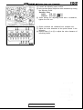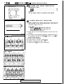
1
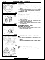
BACKUP
Service Manual
ENGINE
GROUP INDEX
1992 - 1993
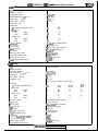
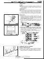
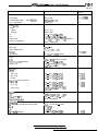
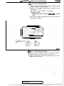
Introduction
FOREWORD
............................
Engine
The information contained in this service manual
has been prepared for the professional automotive
technician involved in daily repair operations. Information in this manual is divided into groups by
engine models. Each group is further divided to
address individual components within the group.
These groups contain general information, specification, removal and installation, disassembly and
reassembly procedures for the components. The
first page of each group contains an alphabetical
index to assist in finding the location of the
component. The information, descriptions and specifications were in effect at the time this manual
was released.
4G1l . . . . . . . . . . . . . . . . . . . . . . . . . . . . . . . . . . . . . . . .
mm
4G3
3 ...............,........................
4G6 <1992>> . . . . . . . . . . . . . . . . . . . . . . . .
mm
4G9
9 . . . . . . . . . . . . . . . . . . . . . . . . . . . . . . . . . . ...*.. m
6G7
7 ........................................
WE SUPPORT
VOLUNTARY TECHNICIAN
CERTIFICATION THROUGH
4G6 <1993>> . . . . . . . . . . . . . . . . . . . . . . . .
National lnstit~te for
AUTOMOTIVE
SERVICE
EXCELLENCE
Mitsubishi Motors Co[poration reserves the right to make changes in
dew? or to make addltlons to or improvements in its products WIthout
impoang any obligations upon itself to install them on its products
previously manufactured.
@ 1992 Mitsubishi Motors Corporation
Printed in Japan
CCT
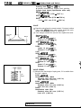
INTRODUCTION
:,
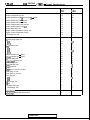
CONTENTS
ENGINE MODEL TABLE . . . . . . . . . . . . . . . . . . . . . . . . . . . . . . . . . . . . . . . . 4
EXPLANATION OF MANUAL CONTENTS . . . . . . . . 2
FORM-IN-PLACE GASKET . . . . . . . . . . . . . . . . . ..I................ 6
Disassembly . . . . . . . . . . . . . . . . . . . . . . . . . . . . . . . . . . . . . . . . . . . . . . . . . . . . . . . . 6
Form-In-Place Gasket Application ._...................... 6
Surface Preparation . . . . . . . . . . . . . . . . . . . . . . . . . . . . . . . . . . . . . . . . . . . . 6
SPECIAL TOOL NOTE . . . . . . . . . . . . . . . . . . . . . . . . . . . . . . . . . . . . . . . . . . . . 5
TORQUE REFERENCES . . . . . . . . . . . . . . . . . . . . . . . . . . . . . . . . ..I..... 5
1.
._
, ‘-:
:
. :
2
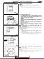
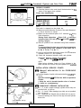
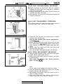
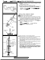
INTRODUCTION
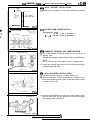
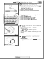
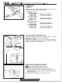
EXPLANATION OF MANUAL CONTENTS
Maintenance and Servicing Procedures
(1) A diagram of the component parts is
provided near the front of each section in
order to give the reader a better understanding of the installed condition of
component parts.
(2) The numbers provided within the diagram
indicate the sequence for maintenance
and servicing procedures; the symbol m
indicates a non-reusable part; the tightening torque is provided where applicable.
I
0 Removal steps:
The part designation number corresponds
to the number in the illustration to indicate
removal steps.
l Disassembly steps:
The part designation number corresponds
to the number in the illustration to indicate
disassembly steps.
0 Installation steps:
Specified in case installation is impossible
in reverse order of removal steps. Omitted if installation is possible in reverse
order of removal steps.
ia
l Reassembly steps:
Specified in case reassembly is im$ossible in reverse order of disassembly
Omitted if reassembly is possible
verse order of disassembly steps.
Classification of Major Maintenance/
Service Points
When there are major points relative to maintenance and servicing procedures (such as essential
maintenance and service points, maintenance and
service standard values, information regarding the
use of special tools, etc.), these are arranged
together as major maintenance and service points
and explained in detail.
GAO: Indicates that there are essential points for
removal or disassembly.
I)A4: Indicates that there are essential points for
installation or reassembly.
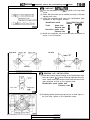
Symbols for Lubrication, Sealants and
Adhesives
Information concerning the locations for lubrication and for application of sealants and adhesives
is provided, by using symbols, in the diagram of
component parts, or on the page following the
component parts page, and explained.
& . . Grease
(multrpurpose grease unless there is
a brand or type specified)
. . . . . Sealant or adhesive
i
. . . . . Brake fluid, automatic transmission
fllid or air conditioning compressor
:m . . . . . Engine oil or gear oil
I
TSB Revision
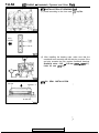
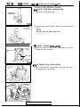
INTRODUCTION
3
Indicates the
section title.
Denotes non-reusable
This number corresponds to the
number appearing in “Removal
steps”, “Disassembly steps”, “lnstallation steps” or “Reassembly
steps”
I
Operating procedures, cautions,
etc. on removal, installation, disassembly and reassembly are described.
I
TSB Revision
4
INTRODUCTION
ENGINE MODEL TABLE - 1992
Engine
Series,
4Gl
4G3
4G6
4G9
6G7
4693
1.8 (1 IO)
In-line, SOHC
E$po LRV
6672
3.0 (I 83)
6O”V. SOHC
(per bank)
bgmante,
h&ntero, Truck
6G72
3.0 (183)
6O”V. DOHC
(per bank)
Diamante, 3000GT
6G72 Turbo
3.0 (183)
6O“V. DOHC
(per bank)
4
3000GT
.K
c:
2.4(146)
In-line, SOHC
4
E$po-LRV. Expo
4G93
1.8 (1 IO)
In-line, SOHC
4
@age, Expo LRV
6672
3.0 (I 83)
6O”V. SOHC
(per bank)
2
Diamante,
Mhtero, Truck
6672
3.0 (183)
6O”V, DOHC
(per bank)
4
C$mante, 3000GT
6G72 Turbo
3.0 (183)
6O”V. DOHC
(per bank)
4
3600GT
ENGINE MODEL TABLE - 1993
4664
4G9
6G7
.
1 TSB Revision
INTRODUCTION
6
.
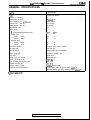
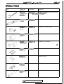
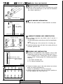
SPECIAL TOOL NOTE
1
Please refer to the special tool cross reference chart which is located in the service manual at the beginning of
each group, for a cross reference from the MMC special tool number to the special tool number that is
iiS
*‘l
available in your market.
*.j,
“...!: ‘/’
l”
TORQUE REFERENCES
General tightening torque is as shown in the following table.
The specific part tightening torque is shown at the beginning of each group.
Flange bolt
Bolt with spring washer
Size mm
(dia. x pitch)
Head mark 4
Head mark 7
Head mark 10
Head mark 4
Heaid. i-MC 7
Nm
Nm
Nm
Nm
Nm
ft.lbs.
ft.lbs.
ft.lbs.
ft.lbs.
ft.lbS.
5 x 0.8
6x 1.0
8 x 1.25
10x1.25
12x 1.25
14x1.5
NEW TIGHTENING METHOD - BY USE OF BOLTS TO BE TIGHTENED IN PLASTIC AREA
A new type of bolts, to be tightened in plastic area, is currently used in so’me parts of the engine. The
tightening method for the bolts is different from the conventional one. Be sure to observe the method
described in the text when tightening the bolts.
Service limits are provided for the bolts. Make sure that the service limits described in the text are strictly
observed.
l Areas where the bolts are in use:
(1) Cylinder head bolts
(2) Main bearing cap bolts
(3) Connecting rod cap bolts
Remarks:
The bolts in (1) and (2) apply to the 4G6 <I 993> and 4G93 engines.
The bolts in (3) apply to the 4G15, 4G6 <1993> and 4693 engines.
l
Tightening Method
After tightening the bolts to the specified torque, tighten them another 90” or 180” (twice 90”). The
tightening method varies on different areas. Observe the tightening method described in the text.
TSB Revision
INTRODUCTION
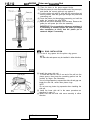
FORM-IN-PLACE GASKET
The engine has several areas where the form-in-place gasket (FIPG) is in use. To ensure that the gasket fully
serves its purpose, it is necessary to observe some precautions when applying the gasket. Bead size,
continuity and location are of paramount importance. Too thin a bead could cause leaks. Too thick a bead, on
the other hand, could be squeezed out of location, causing blocking or narrowing of the fluid feed line. To
eliminate the possibility of leaks from a joint, therefore, it is absolutely necessary to apply the gasket evenly
without a break, while observing the correct bead size.
The FIPG used in the engine is a room temperature vulcanization (Rn/) type and is supplied in a loo-gram
tube (Part No. MD970389 or MD9971 10). Since the RTV hardens as it reacts with the moisture in the
atmospheric air, it is normally used in the metallic flange areas. The FIPG, Part No. MD970389, can be used
for sealing both engine oil and coolant, while Part No. 997110 can only be used for engine oil sealing.
Disassembly
The parts assembled with the FIPG can be easily disassembled without use of a special method. In some
cases, however, the sealant between the joined surfaces may have to be broken bylightly striking with a
mallet or similar tool. A flat gasket scraper may be lightly hammered in between the joined surfaces. In this
case, however, care must be taken to prevent damage to the joined surfaces.
Surface Preparation
Thoroughly remove all substances deposited on the gasket application surfaces, using a gasket scraper or
wire brush. Check to ensure that the surfaces to which the FIPG is to be applied is flat.‘ Make sure that there
are no oils, greases and foreign substances deposited on the application surfaces. Do:not forget to remove
the old sealant remaining in the bolt holes.
5
Form-In-Place Gasket Application
When assembling parts with the FIPG, you must observe some precautions, but the procedure is very simple
as in the case of a conventional precut gasket.
Applied FIPG bead should be of the specified size and without breaks. Also be sure toencircle the bolt hole
circumference with a completely continuous bead. The FIPG can be wiped away unless it is hardened. While
the FIPG is still moist (in less than 15 minutes), mount the parts in position. When the parts are mounted,
make sure that the gasket is applied to the required area only.
The FIPG application procedure may vary on different areas. Observe the procedure described in the text
when applying the FIPG.
TSB Revision
4G15
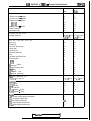
CONTENTS
BRACKET ................................................................
CRANKSHAFT, FLYWHEEL AND
DRIVE PLATE ........................................................
CYLINDER HEAD AND VALVES ........................
EXHAUST MANIFOLD AND
WATER PUMP ....................................................
FRONT CASE AND OIL PUMP ............................
FUEL AND EMISSION PARTS ............................
GENERAL INFORMATION ................................
GENERAL SPECIFICATIONS ............................
GENERATOR AND IGNITION SYSTEM ........
53
51
33
28
39
22
2
5
14
INTAKE MANIFOLD ............................................
PISTON AND CONNECTING ROD ....................
ROCKER ARMS AND CAMSHAFT ....................
SEALANT ................................................................
SERVICE SPECIFICATIONS ................................
SPECIAL TOOLS ....................................................
THROlTLE BODY ................................................
TIMING BELT ........................................................
TORQUE SPECIFICATIONS ................................
26
43
30
11
6
12
24
17
10
IlA-2
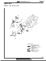
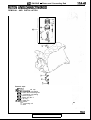
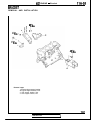
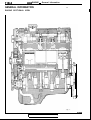
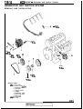
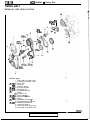
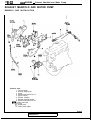
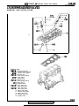
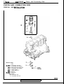
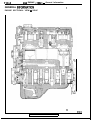
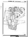
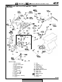
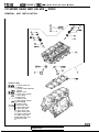
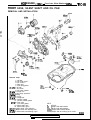
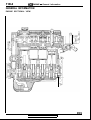
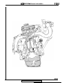
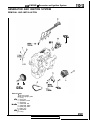
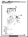
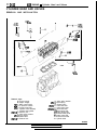
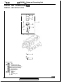
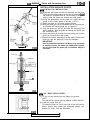
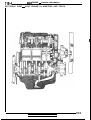
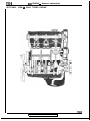
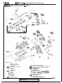
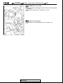
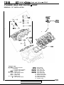
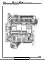
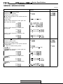
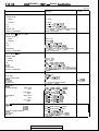
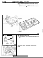
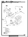
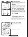
4Gl ENGINE - General Information
GENERAL INFQRMATION
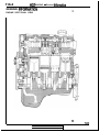
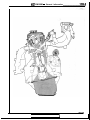
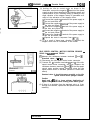
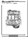
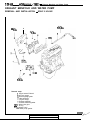
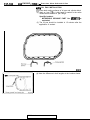
ENGINE SECTIONAL VIEW
3
1 EN0086
TSB Revision
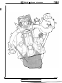
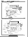
4Gl ENGINE - General Information
TSB Revision
1
VA-4
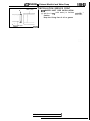
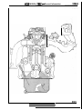
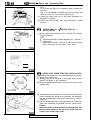
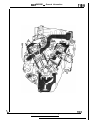
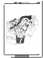
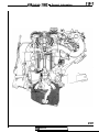
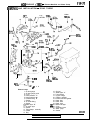
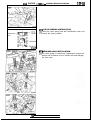
4Gl ENGINE - General Information
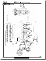
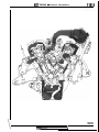
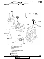
UBRICATION SYSTEM
0’
t7;
ii
I
1 TSB Revision
‘ZP
:
ii
OTJ
09
4Gl ENGINE - General Specifications
GENERAL SPECIFICATIONS
Items
Specifications
We
Number of cylinders
Combustion chamber
Total displacement cm3 (cu.in.)
Cylinder bore
mm (in.)
Piston stroke
mm (in.)
Compression ratio
Valve timing
( ): Camshaft identification mark
Intake valve
Opens
BTDC
Closes
ABDC
Exhaust valve
BBDC
Opens
Closes
ATDC
Lubrication system
Oil pump type
Cooling system
Water pump type
EGR valve
Injector type and number
Injector identification No.
Fuel regulated pressure kpa (psi)
Throttle bore mm (in.)
Throttle position sensor
Closed throttle position switch
In-line OHV, SOHC
4
Pentroof type
1,468 (89.58)
75.5 (2.972)
82 (3.228)
9.2
(1 I*’
(6)**
14”
51”
15”
53”
51”
57”
14”
15”
Pressure feed, full-flow filtration
Trochoid type
Water-cooled forced circulation
Centrifugal impeller type
Single type
Electromagnetic, 4
BDH182
335 (47.6)
46(1.811)
dariable resistor type
Contact type, within idle speed control motor”
Movable contact type within throttle position sensor*’
Y’
1: up to .--1992 models
“2: From 1993 models
1 TSB Revision
I
1 IA-6
4Gl ENGINE - Service Specifications
SERVICE SPECIFICATIONS
“”
Items
Standard value
Limit
d.05 (.0020)
0.2(.008)
"0.2 (.008)
Cylinder head
Flatness of gasket surface
Grinding limit of gasket surface
t Total resurfacing depth of both cylinder
head and cylinder block
Overall height
Oversize rework dimensions of valve guide hole
(both intake and exhaust)
0.05 (.002)
0.25(.010)
0.50 (.020)
Oversize rework dimensions of intake valve
seat ring hole (primary)
0.3 (.012)
0.6(.024)
Oversize rework dimensions of intake valve
seat ring hole (secondary)
0.3 (.012)
0.6 (.024)
Oversize rework dimensions of exhaust valve
seat ring hole
0.3 (.012)
0.6 (.024)
35.43-35.45(1.3949-1.3957)
35.73-35.75(1.4067-1.4075)
Camshaft
Cam height
Intake
Exhaust
Journal diameter
3il clearance
38.78 (1.5268)
39.10 (1.5394)
45.93-45.94(1.8083-1.8087)
0.06-0.10(.0024-.0039)
qockerarm
.D.
3ocker arm-to-shaft clearance
18.91 -18.93(.7445-.7453)
0.01 -0.04(.0004-.0016)
qockerarmshaft
I.D.
3verall length
Intake
Exhaust
mm (in.)
106.9-107.1 (4.209-4.217)
12.05-12.07 (.4744-.4752)
12.25- 12.27 (.4823-.4831)
12.50-12.52 (.4921 -.4929)
3
1
“1
'$
1,
27.42-27.44(1.0795-1.0803)
27.72-27.74(1.0913-1.0922)
32.43-32.45 (1.2768-1.2776)
32.73-32.75 (1.2886-1.2894)
18.89-18.90(.7437-.7441)
365(14.37)
346(13.62)
TSB Revision
I)
1
1:
!
38.28 (1.5071)
38.60(1.5197)
0.1 (.004)
4Gl ENGINE - Service Specifications
mm (in.)
.,_
Items
Valve spring
Free height
Intake
Exhaust
-oad/installed height
Intake
Exhaust
3ut-of-squareness
halve guide
3verall length
Intake
Exhaust
.D.
I.D.
;ervice size
‘Tess-in temperature
lalve seat
;eat angle
lalve contact width
Gnkage
iervice size
,-i ,
-7, ,i ,,- <
100.75 (3.9665)
101.05 (3.9783)
6.57 - 6.58 (2587 - .2591)
6.53 - 6.55 (2571 - .2579)
45” - 45”30’
1 .o (.039)
1.5 l.059)
0.5 (020)
1 .o (.039)
0.02 - 0.05 (0008 - .0020)
0.05 - 0.09 (.0020 - .0035)
0.10 (.0039)
0.15 (.OOSS)
0.07 (.0028) Up to 1992 models
0.09 (.0035) From 1993 models
0.17 (0067)
Exhaust
46.1 (1.815)
46.8 (1.843)
45.1 (1.776)
45.8 (1.803)
230/40 (51/I .57)
290140 (64/l .57)
Max. 2”
4”
N/mm (Ibs./in.)
44 ( 1.732)
49.5 (1.949)
6.60 - 6.62 (.2598 - .2606)
12.055 - 12.065 (4746 - .4750)
0.05 (.002), 0.25 (.Ol). 0.50 (02) oversize
Room temperature
43”30’ - 44”
0.9 - 1.3 (035 - .051)
..
0 . 2 (.008)
0.3 LO1 2), 0.6 (024) oversize
\-TSR Revision
..“_
i
.
1 .t..7/
Limit
Standard value
Valve
Overall length
Intake
Exhaust
Stem diameter
Intake
Exhaust
Face angle
Thickness of valve head (margin)
Intake
Exhaust
Stem-to-guide clearance
Intake
Exhaust
Valve clearance
Intake
..“..
I
IIA-8
4Gl ENGINE - Service Specifications
mm (in.)
Items
Standard value
Limit
Piston
75.48 - 75.50 (2.9716 - 2.9724)
0.02 - 0.04 (0008 - .0016)
0.25 t.01). 0.50 (.02), 0.75 (.03), 1 .OO (.04)
oversize
O.D.
Piston-to-cylinder clearance
Service size
Piston ring
End gap
No. 1 ring
No. 2 ring
Oil ring
Ring-to-ring groove clearance
0.20 - 0.40 l.0079 - .0157)
0.20 - 0.35 (.0079 - .0138)
0.20 - 0.70 LOO79 - .0276)
0.8 (.031)
0.8 f.031)
1 .o i.039)
No. 1 ring
No. 2 ring
Service size
0.03 - 0.07 (.0012 - .0028)
0.02 - 0.06 f.0008 - .0024)
0.25 (.Ol), 0.50 (.02), 0.75 (.03), 1 .OO (04)
oversize
0.1 (.004)
0.1 i.004)
Piston pin
O.D.
Press-in load N (psi)
Press-in temperature
18.003 - 18.005 l.7088 - .7089)
5,000 - 15,000 (1 ,102 - 3,307)
Room temperature
Connecting rod
Big end center-to small end center length
Bend
Twist
Big end side clearance
130.95- 131.05 (5.1555-5.1594)
0.05 (.0020)
0.1 (.004)
0.10 - 0.25 (.0039 - .0098)
Crankshaft
End play
Journal O.D.
Pin O.D.
Dut-of-roundness and taper of journal and pin
3il clearance of journal
3il clearance of pin
0.05-0.18 (.0020- .0071)
48 (1.89)
42 (1.65)
0.005 (.0002)
0.02 - 0.05 (.0008 - .0020)
0.02 - 0.05 (.0008 - .0020)
Cylinder block
.D.
Ilatness of gasket surface
Grinding limit of gasket surface
Total resurfacing depth of both cylinder
block and cylinder head
3verall height
75.50 - 75.53 (2.9724 - 2.9736)
0.05 i.002)
255.9 - 256.1 (10.075 - 10.083)
TSB Revision
0.4 f.016)
0.3 (.012)
0.1 i.004)
0.1 (.004)
0.1 i.004)
*0.2 (.008)
4Gl ENGINE - Service Specifications
rn:fq, (in,
i ,I :, i /
Items
Standard value
Oil pump
Tip clearance
Side clearance
Body clearance
0.03 - 0.08 LOOI 2 - .0031)
0.04-0.10(.0016-.0039)
O.lO-0.18(.0039-.0071)
Drive belt deflection
New belt
Used belt
5.5 -7.0 (.22 - .28)
8.0 (.32)
Injector
Coil resistance fI?
13 - 16 at 20°C (68°F)
Throttle position sensor
Resistance kR
3.5-6.5
Idle speed control motor
Coil resistance rc1
5 - 35 at 20°C (68°F)
Idle air control motor
Coil resistance 0
28 - 33 at 20°C (68°F)
Idle speed control motor position sensor
Resistance kfi
4-6
1 TSB Revision
Limit
.’
0 . 3 5 (.Orl38)
1 IA-IO
4Gl ENGINE - Torque Specifications
TORQUE SPECIFICATIONS
Nm
-
ftlbs.
i
8
7
10
17
17
61
10
18
9
Generator and ignition system
Oil level gauge guide mounting bolt
W a t e rpump
pulley bolt
Generator brace bolt
Generator brace mounting bolt
Generator pivot nut
Crankshaft bolt
Crankshaft pulley bolt
Spark plug
Distributor
11
9
14
24
23
85
14
25
12
Timing belt
Engine support bracket, left
Tensioner bolt
Camshaft sprocket bolt
36
24
70
Fuel and emission parts
Throttle body mounting bolts
Fuel rail mounting bolts
Fuel pressure
regulator bolts
EGR valve (California) mounting bolts
19
12
9
13
Throttle body
Throttle position sensor attaching bolts
2.0
1.5
Intake manifold
Cable bracket bolt
Engine coolant temperature gauge unit
Engine coolant temperature sensor
Therm0 switch
flater outlet fitting bolt
Thermostat housing bolt and nut
Intake manifold stay bolt
Engine support bracket stay
Intake manifold bolt and nut
14
11
30
8
19
18
22
36
18
11
8
22
6
14
13
16
26
13
Exhaust manifold and
Exhaust manifold cover
Exhaust manifold cover
Exhaust manifold cover
Exhaust manifold nut
Vater inlet pipe bolt
Vater pump bolt
Ixygen sensor
30
9
24
18
14
14
45
22
7
18
13
11
11
33
1.8
32
15
1.3
24
11
jocker
jocker
locker
iocker
water pump
“A” bolt
“A” and “B” mounting bolt
“B” bolt
arms and camshaft
cover bolt
arm shaft bolt
arm lock nut
TSB Revision
ii
‘7
26
17
51
14
9
7
9
461 ENGINE - Torque Specifications / Sealant
_ .” .c
Nm
ft.lbs.‘, I. ‘-,.‘.,; $8;
Cylinder head and valves
Cylinder head bolt
73
53
Front case and oil pump
Oil pan
drain plug
Oil pan bolt
Oil screen bolt
Oil relief valve plug
Front case bolt
Oil pump cover screw
40
7
19
45
I4
IO
29
5
14
33
11
8
Piston and connecting rod
Connecting rod cap nut
20 + I/4 turns
14.5 + l/4 turns
Crankshaft, flywheel and drive plate
Flywheel and drive plate
Rear plate bolt
Bell housing cover bolt
Oil seal case bolt
Bearing cap bolt
3il pressure switch
135
11
9
11
53
19
98
8
7
8
38
14
Bracket
Exhaust pipe support bracket
Engine support bracket, front
7011 stopper bracket, front
3011 stopper bracket, rear
36
60
65
120
26
43
47
87
SEALANT
Items
Specified sealant
Quantity
Therm0 switch
Engine coolant temperature sensor
Engine coolant temperature gauge unit
Oil pan
Oil pressure switch threads
3M Nut Locking part No. 4171 or equivalent
3M Nut Locking part No. 4171 or equivalent
3M ATD Part No. 8660 or equivalent
Mitsubishi Genuine Part No. MD970389 or equivalent
3M ATD Part No. 8660 or equivalent
As
As
As
As
As
TSB Revision
required
required
required
required
required
1 IA-12
4Gl ENGINE - Special Tools
SPECIAL TOOLS
Tool
MD99801 1
Crankshaft rear
oil seal installer
MD99801 I-01
Installation of crankshaft rear oil seal
MD998713-01
Installation of camshaft oil seal
Crankshaft front
oil seal installer
MD99871 3
Camshaft oil seal
,.i
..
Removal of oil pan
ompresslon 0
TSB Revision
4Gl ENGINE - Special Tools
Valve stem seal
compressor
Flywheel stopper
1 TSB Revision
1 IA-14
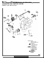
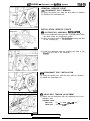
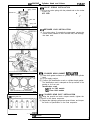
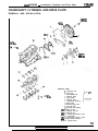
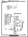
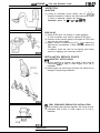
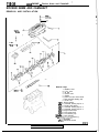
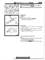
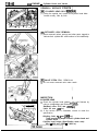
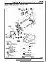
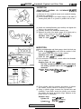
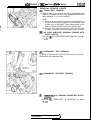
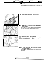
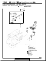
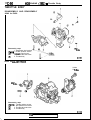
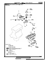
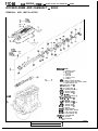
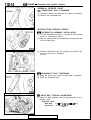
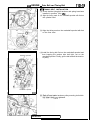
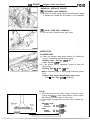
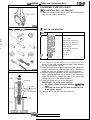
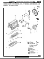
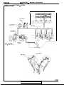
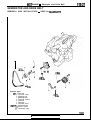
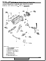
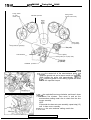
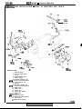
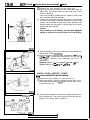
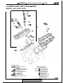
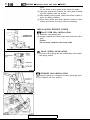
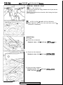
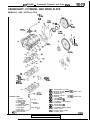
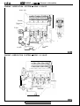
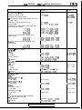
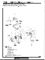
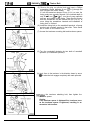
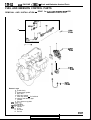
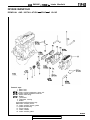
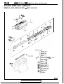
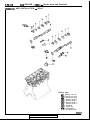
4Gl ENGINE - Generator and Ignition System _,
*
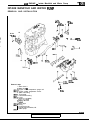
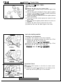
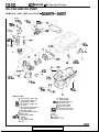
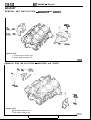
GENERATOR AND IGNITION SYSTEM
REMOVAL AND INSTALLATION
12 Nm
9 ftJp3.
7
23 Nm
Ji
14 Nm
10 ft.lbs.
” Rm/b=I
n
\!
I
24Nr;l
17 ft.lbs.
9Nm
I
85 Nm
81 ft.lbs.
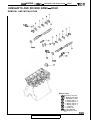
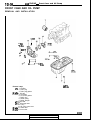
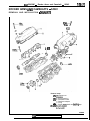
Removal steps
1, Oil level gauge
2. Oil level gauge guide
3. O-ring
+C4 4. Drive belt
5. Water pump pulley
6. Generator brace
7. Generator
(IA!) +B4 8. Crankshaft bolt
9. Special washer
IO. Crankshaft pulley
11. Damper pulley
12. Spark plug cable
13. Spark plug
*A4 ‘ll. ;.s;;$butor
. -
1 EN0325
1 TSB Revision
1
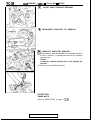
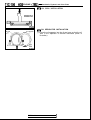
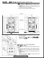
461 ENGINE - Generator and Ignition System
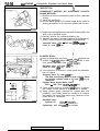
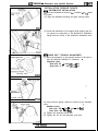
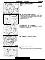
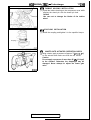
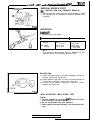
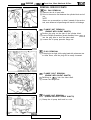
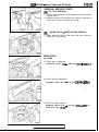
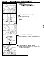
REMOVAL SERVICE POINT
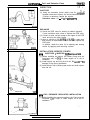
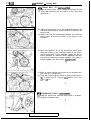
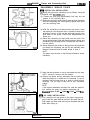
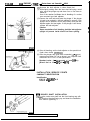
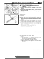
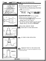
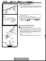
OAo CRANKSHAFT BOLT REMOVAL
(I) Using the special tool, hold the drive plate or flywheel.
(2) Remove the crankshaft bolt.
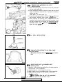
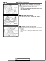
INSTALLATION SERVICE POINTS
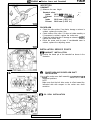
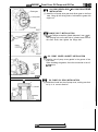
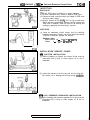
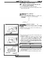
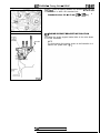
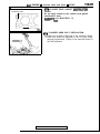
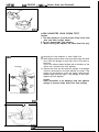
r)A4 DISTRIBUTOR ASSEMBLY INSTALLATlOy /
(1) Turn the crankshaft to bring the No. I cylinder piston to the
top dead center on compression stroke.
(2) Align the mating mark on thedistributor housing with that
on the coupling key.
1 EL004
(3) Install the distributor with the coupling key fitted in the
keyway at the end of the camshaft.
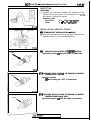
r)64 CRANKSHAFT BOLT INSTALLATION
(I) Using the special tool, hold the drive plate or flywheel.
(2) Install the crankshaft bolt.
F
1 EN0326
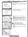
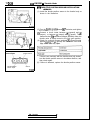
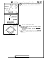
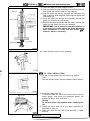
#c4 DRIVE BELT TENSION ADJUSTMENT
(I) Adjust the belt deflection with the adjusting bolt to the
standard value.
Standard value:
New belt
5.5 - 7.0 mm (.22 - .28 in.)
Used belt
8.0 mm (.32 in.)
1 EN029'
1 TSB Revision
4Gl ENGINE - Generator and Ignition System
6EN059E
(2) Or using a tension gauge, adjust the tension to the standard
value.
Standard value:
New belt
5 0 0 - 700 N (116 - 154 Ibs.)
Used belt
400 N (88 Ibs.)
(3) Tighten the lock bolt to the specified torque.
(4) Tighten the nut for pivot bolt to th$ specified torque.
6EN0591
1 TSB Revision
I
I
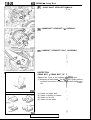
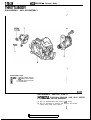
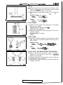
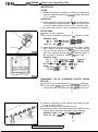
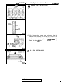
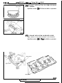
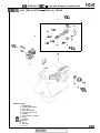
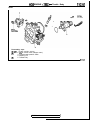
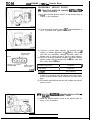
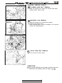
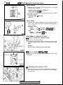
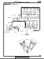
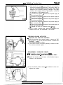
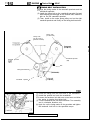
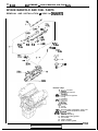
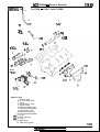
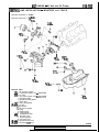
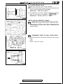
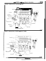
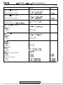
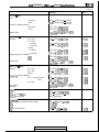
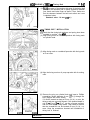
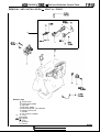
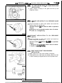
461 ENGINE - Timing Belt
TIMING BELT
REMOVAL AND INSTALLATION
2bnhll
17 ft.lbs.
I
7
8
d
Removal steps
1. Timing belt upper cover
2. Timing belt lower cover
@I$ eC4 3. Timing belt
4. Engine support bracket, left
5. Tensioner spring
+B4 6. Tensioner
7. Crankshaft sprocket
OBO
8. Flange
$I$ *A4 9. Camshaft sprocket bolt
10. Camshaft sprocket
1 EN0327
TSB Revision
I
461 ENGINE - Timing B e l t
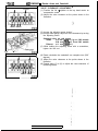
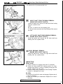
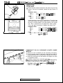
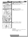
REMOVAL SERVICE POINTS ~
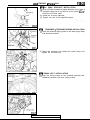
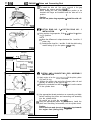
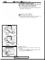
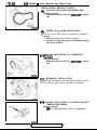
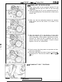
OAo TIMING BELT REMOVAL
(1) Mark belt running direction for reference in reinstallation.
(2) Loosen the tensioner bolts and move the tensioner toward
the water pump.
(3) Remove the timing belt.
NOTE
(1) Water or oil on the belt shortens its life drastically, so
the removed timing belt, sprocket, and tensioner must
be kept free from oil and water. Do not immerse parts in
cleaning solvent.
(2) If there is oil or water on any part, check the front case
oil seal, camshaft oil seal and wfter pump for leaks.
,
4Bo CRANKSHAFT SPROCKET REldOVAL
r-
@o CAMSHAFT SPROCKET BOLT LOOSENING
INSPECTION
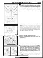
TIMING BELT
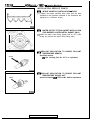
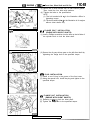
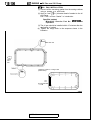
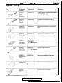
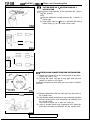
Replace belt if any of the following conditions exist.
(1) Hardening of back rubber side is glossy without resilience
and leaves no indent when pressed with fingernail.
461 ENGINE - Timing Belt
(2) Cracks on rubber back
(3) Cracks or peeling of canvas
(4) Cracks on rib root
(5) Cracks on belt sides
Peeling
Cracks
1 EN024E
(6) Abnormal wear of belt sides. The sides are normal if they
are sharp as if cut by a knife.
Roundededge
Abnormal wear
(Fluffy strand)
8EN006;
(7) Abnormal wear on teeth
(8) Missing tooth
Rubber exposed
Tooth missing
and canvas fiber
8EN006
MIT308239
/
I
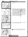
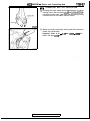
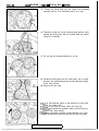
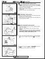
INSTALLATION SERVICE POIFTS
I)A4 CAMSHAFT SPROCKET BOLT TIGHTENING
01 PO281
I)B4 TENSIONER INSTALLATION
(I) Move the tensioner pulley toward the water pump and
tighten the tensioner mounting bolts.
Water
pump
1 EN0003
TSB Revision
11 A-20
4Gl ENGINE - Timing Belt
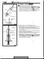
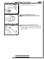
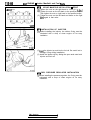
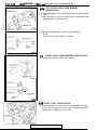
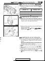
I)cg TIMING BELT INSTALLATION (1) Align the timing marks on the camshaft sprocket and the
crankshaft sprocket with their timing marks.
(2) Set the timing belt first on crankshaft sprocket and then
keeping the tension side belt tight, set on the camshaft
sprocket.
4
1 EN033
(3) Loosen the tensioner mounting bolts @ and 0.
(4) Check that the belt completely meshes with the sprocket.
Also check the timing marks on the sprockets for align-
4Gl ENGINE - Timina Belt
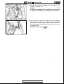
(5) Turn the crankshaft clockwise by 3 crankshaft s@Cxket
I
teeth.
(6) Tighten bolt @ first and then bolt 0. If bolt @ is tightened
first, the tensioner will turn together with the bolt, resulting
in an overtensioned belt.
1 ENOOOE
\
il
(7) Check the belt tension. Hold the tensioner and ‘timing belt
together by hand and give the belt a slight thumb pressure
at a point level with tensioner center. Make sure that belt
cog crest comes as deep as about l/4 of the width of the
slot side tensioner bolt head.
Tensioner slot side
ll4of
bolt head
1 EN025
TSB Revision
IIA-22
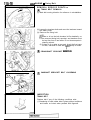
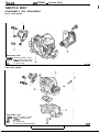
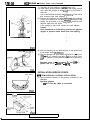
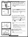
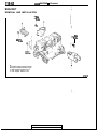
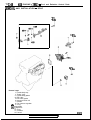
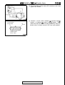
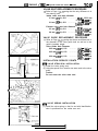
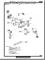
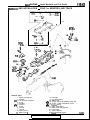
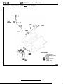
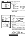
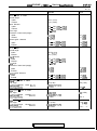
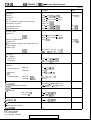
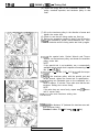
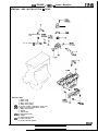
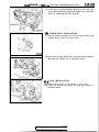
461 ENGINE - Fuel and Emission Parts
FUEL AND EMISSION PARTS
REMOVAL AND INSTALLATION
19 Nm
;; 14 ft.lbs.
Removal steps
1. Throttle body
2. Gasket
3. Injectors and fuel rail
4. Insulator
eB4 ;. Fuw&ressure regulator
7: Insulator
*A4 8. Injector clip
*A4 9. Injector
10. O-ring
11. Grommet
12. Fuel rail
13. EGR valve (For California)
14. Gasket
1 EN0238
TSB Revision
461 ENGJNE - Fuel and Emission Parts
INSPECTION
‘,.$
::.
INJECTORS
‘I’:. ,L
(1) Using an ohmmeter (circuit tester), test for, cont$u~ty,
between terminals of injector; the circuit should be closed.
If failure is detected, replace the injector.
Standard value: 13 - 16 Cn [at 20°C (68”F)l
6FU192C
EGR VALVE
(1) Check the EGR valve for sticking or carbon deposits.
If such conditions exist, clean or replace the EGR valve.
(2) Connect a hand vacuum pump to the nipple of the EGR
valve and plug the other nipple.
(3) Apply a vacuum of 500 mmHg (19.7 in.Hg) to make sure
that vacuum is maintained. If there is a leak, replace the
EGR valve.
In addition, check the valve for its opening and closing
motion by applying and removing vacuum.
6EM038~
INSTALLATION SERVICE POINTS
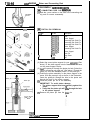
#A4 INJECTORS / INJECTOR CLIP INSTALLATICjbi
(1) Before installing an injector, the rubber O-ring must be
lubricated with a *drop of clean engine oil to aid in
installation.
(2) Install injector top end into the fuel rail. Be careful not to
damage O-ring during installation.
(3) Install injector clip by sliding open ends onto both injector
and fuel rail.
1 EN025C
I)64 FUEL PRESSURE REGULATOR INSTALLATION
(1) Before installing the pressure regulator, the O-ring must be
lubricated yjth a drop of clean engine oil to aid in
installation.
6FUO71,
TSB Revision
1 M-24
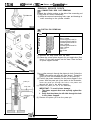
4Gl ENGINE - Throttle Body
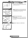
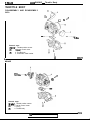
THROTTLE BODY
DISASSEMBLY AND REASSEMBLY
Up to 1992 models
1
2Nm
1.4 ftlbs.
Disassembly steps
4ArJ bA4 1. Throttle position sensor
2. Idle speed control motor
3. Throttle valve set screw
4. Throttle body
6FU1292
From 1993 models
“p
2Nm
1.4 ft.lbs.
Disassembly steps
8:; I)A4 I. Throttle position sensor
2. Idle arr control motor
3. O-ring
4. Throttle body
4BO
5. Fixed speed adjusting screw
] TSB Revision
1 EN0336
461 ENGINE - Throttle Bodv
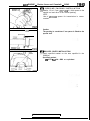
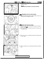
DISASSEMBLY SERVJCE POINTS
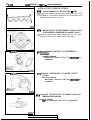
6Ab THROTTLE POSITION SENSOR AND IDLE SPEED
CONTROL MOTOR / IDLE AIR CONTROL IMOTOR
REMOVAL
(1) DO not disassemble the sensor and motor.
(2) DO not immerse in solvent the sensor and motor to clean.
Clean them with shop towel.
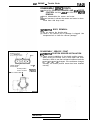
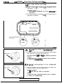
aB0 THROlTLE
BODY REMOVAL
(1) Do not remove the throttle valve.
(2) Check if the vacuum port or passage is clogged. Use
compressed air to clean the vacuum passage.
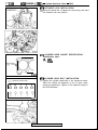
Closed throttle position switch*
Throttle Dosition
/
round
Throttle position
sensor output
Throttle position
sensor connector
View P
REASSEMBLY SERVICE POINT
+A4 THROTTLE POSITION SENSOR INSTALLATION
(1) Check correct installation of the throttle position sensor.
While moving the throttle lever in both open and close
directions, check to see that resistance between terminals
@ and @ or @ and @ changes. If the resistance changes
smoothly, the throttle position sensor has been installed
correctly.
7FUO535
* From 1993 models P
1 EN024S
TSB Revision
llA-26
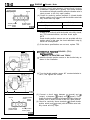
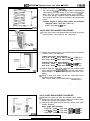
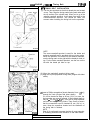
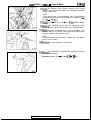
4Gl ENGINE - Intake Manifold
INTAKE MANIFOLD
REMOVAL AND INSTALLATION
14 Nm
IO ft.lbs.
A*
8Nm
Gft.!bs.
-18Nm /
13 ft.lbs.
18Nm
13 ftlbs.
Removal steps
I. Water hose
eC4 2. Engine coolant temperature gauge unit
eB4 3. Engine coolant temperature sensor
*AiJ 4. Thermoswitch
For AIT
5. Water outlet fitting
6. Water outlet fitting gasket
7. Thermostat
8. Outer cable bracket
9. Inner cable bracket
k:E
10. Engine hanger
11. Thermostat housing
12. Intake manifold stay
13. Engine support bracket stay (From 1993
models)
..
14. Intake manifold
15. Intake manifold gasket
[ TSB Revision
I
4Gl ENGINE - Intake Manifold
INSTALLATION SERVICE POINTS
#A4 SEALANT APPLICATION TO THERM0,-(” .SWIT&
*f. ‘; , : i’<, ‘* ; *
Sealant
Specified sealant:
3M Nut Locking Part No. 4171 or equivalent
lEN033E
I)B4 SEALANT APPLICATION TO ENGINE COOLANT
TEMPERATURE GAUGE UNIT
Specified sealant:
3M ATD Part No. 8660 or equivalent
Sealant
9EN009;
I)c4 SEALANT APPLICATION TO ENGINE COOLANT
TEMPERATURE SENSOR
Specified sealant:
3M Nut Locking Part No. 4171 or equivalent
Sealant
9EN0091
1 TSB Revision
1 IA-28
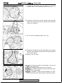
461 ENGINE - Exhaust Manifold and Water Pump*
EXHAUST MANIFOLD AND WATER PUMP
REMOVAL AND INSTALLATION
14 Nm
10 ft.lbs.
30 Nm
22 ft.lbs.
1
7
-
9Nm’
7 klbs.
14 Nm
10 ftlbs.
Removal steps
1. Exhaust manifold cover “A”
2. Oxygen sensor - [1992,1993 (FED) models1
3. Engine hanger
4. Exhaust manifold
5. Exhaust manifold cover “B”
6. Exhaust manifold gasket
7. Water hose
+A4 8. Water inlet pipe
*AC 9. O-ring
10. Water pump
11. Water pump gasket
1 EN0339
TSB Revision
4Gl ENGINE - Exhaust Manifold and Water Pump
O-ring
I
Water inlet pipe
Water
INSTALLATION SERVICE POINT
I)A4 WATER PIPE / O-RING INSTALLATION.‘
pump
.‘ ) & p :.
(1) Wet the O-ring (with water) to facilitateFas-6embly.
Caution
Keep the O-ring free of oil or grease
6EN0594
TSB Revision
1 IA-30
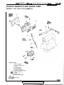
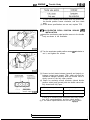
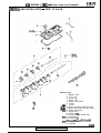
461 ENGINE - Rocker Arms and Camshaft ‘_
ROCKER ARMS AND CAMSHAFT
REMOVAL AND INSTALLATION
1
I
1.8Nm
1.3ft.lbs.
32 Nm
23 ft.lbs.
Removal steps
1. Breather hose
2. PCV hose
3. Rocker cover
4. Rocker cover gasket
)C4 5. Oil seal
eB4 6. Rocker arm and rocker arm shaft
#Bd 7. Rocker arm and rocker arm shaft
8. Rocker arm “D”
9. Wave washer
10. Spacer
11. Rocker arm “C”
12. Rocker arm shaft (exhaust side)
13. Rocker arm “B”
14. Rocker arm spring
15. Rocker arm “A”
16. Rocker arm shaft (intake side)
17. Adjusting screw
18. Nut
+A4 19. Camshaft
1 EN0340
TSB Revision
461 ENGINE - Rocker Arms and Camshaft
qfq/&&l
INSPECTION
CAMSHAFT
(1) Measure the cam height.
Standard value:
38.78 mti (1.5268 ‘in.)
Intake
3 9 . 1 0 m m (1.53& Sii.)
Exhaust
Limit:
38.28 mm (1.5071 in.)
Intake
38.60 mm (1.5197 in.)
Exhaust
.:_j
*
” ,
1 EN009s
ROCKER ARM
l
Check the roller surface. If any dents, damage or seizure is
evident, replace the rocker arm.
l
Check rotation of the roller. If it does not rotate smoothty or
if looseness is evident, replace the rocker arm.
l
Check the inside diameter. If damage or seizure is evident,
replace the rocker arm.
l Check the screw end for wear. If considerable wear is
evident, replace the adjusting screw.
1 EN005:
INSTALLATION SERVICE POINTS
I)A4 CAMSHAFT INSTALLATION
(1) Position the dowel pin of the camshaft as shown in the
illustration.
..
C Timing belt side
Wave washer
Bolt hole
center
I)B4
ROCKER ARM AND ROCKER ARM SHAFT
INSTALLATION
(1) install the rocker arm shaft assembly wnlle respecuny LIW
illustrated positions.
NOTE
Make sure that the bolt hole center is offset toward the
indicated side with respect to the rocker arm shaft
centerline.
1 EN0342
+c4 OIL SEAL INSTALLATION
TSB Revision
1 IA-32
4Gl ENGINE - Rocker Arms and Camshaft
Exhaust 1
VALVE CLEARANCE ADJUSTMENT ~
(1) Position the No. 1 cylinder at the top dead center on
compression stroke.
(2) Adjust the valve clearance at the points shown in the
illustration.
Exhaust 3
Intake 1 Intake 2
lEN015t
(3) Loosen the adjusting screw locknut’.
(4) Using a feeler gauge, adjust the valve clearance by turning
the adjusting screw.
Standard value: on cold engine
0.07 mm (.0028 in.) Up to 1992 models
Intake
0.09 mm (.0035 in.) From 1993 models
0.17 mm (.0067 in.)
Exhaust
(5) While holding the adjusting screw with a screwdriver,
tighten the lock nut.
/
’
/
lEN0122
Exhaust 2
Intake 3
Exhaust 4
Intake 4
1
(6) Rotate clockwise the crankshaft one complete turn (360”
degrees).
(7) Adjust the valve clearance at the points shown in the
illustration.
(8) Repeat steps (3) to (5) to adjust the valve clearance of
remaining valves.
lEN0156
-.----
TSB Revision
4Gl ENGINE - Cylinder Head and Valves
CYLINDER HEAD AND VALVES
REMOVAL AND INSTALLATION
73 Nm
53 ft.lbs.
2-
Removal steps
(JAI) #E4 1. Cylinder head bolt
2. Cylinder head, valve assembly
I)D4 3. Cylinder head gasket
(IBI) #Q 4. Retainer lock
5. Valve spring retainer
#B4 6. Valvespring
7. Intake valve (primary)
8. intake valve (secondary)
(IBM) bC4 9. Retainer lock
10. Valve spring retainer
+B4 11. Valve spring
12. Exhaust valve
$I$ #A4 13. Valve stem seal
14. Valve spring seat
@I$ #A4 15. Valve stem seal
16. Valve spring seat
17. Intake valve guide
18. Exhaust valve guide
19. Intake valve seat (primary)
20. Intake valve seat (secondary)
21. Exhaust valve seat
22. Cylinder head
1ENOlOl
TSB Revision
1 IA-34
461 ENGINE - Cvlinder Head and Valves
REMOVAL SERVICE POINTS j
(IAN CYLINDER HEAD BOLT REMOVAL
OBo RETAINER LOCK REMOVAL
(1) Store the removed valves, springs and other parts, tagged
to indicate their cylinder No. and location to aid reassembly.
$0 VALVE STEM SEAL REMOVAL
(1) Do not reuse removed valve stem seals.
i:
;".
INSPECTION
.,
CYLINDER HEAD
(1) Check the cylinder head gasket &$-face for flatness by
using a straightedge and thicknessygauge.
Standard value: 0.05 mm (.0020 jn.)
Limit: 0.2 mm (.008 in.)
(2) If the service limit is exceeded, correct to meet specifica>:
tion.
Grinding limit: *0.2 m m (.008 ind
* Total resurfacing depth of bo$ cylinder head and
cylinder block
Cylinder head height (Specifieatidn when new):
106.9 - 107.1 mm (4.209 - 4.217 in.)
TSB Revision
4Gl ENGINE - Cylinder Head and Valves
6EN054:
Free
height
1 EN0264
I
VALVE
(1) Check the valve face for correct contact. If incorrect, reface
using valve refacer. Valve should“ma,ke a uniform contact
with the seat at the center of valve ‘face.
(2) If the margin is smaller than the ser@cefimit, replace the
valve.
Standard value:
1.0 mm (.039 in.)
Intake
1.5 mm (.059 in.)
Exhaust
Limit:
Intake
0.5 mm (.020 in.)
1.0 mm (.039 in.)
Exhaust
VALVE SPRING
(1) Measure the free height of the spring and, if it is smaller
than the limit, replace.
Standard value:
46.1 mm (1.815 in.)
Intake
48.8 mm (1.643 in.)
Exhaust
Limit:
45.1 mm (1.776 in.)
Intake
45.8 mm (1.803 in.)
Exhaust
(2) Measure the squareness of the spring and, if the limit is
exceeded, replace.
Standard value: 2” or less
Limit: 4”
Valve
guide
1 EN027!
0.9 - 1.3 mm
(.035 - ,051 in.)
0.9 - 1.3 mm
(.035 - ,051 in.)
VALVE GUIDE
(1) Measure the clearance between the valve guide and the
valve stem. If the limit is exceeded, replace the valve guide
or the valve, or both.
Standard value:
0.02 - 0.05 mm (.OOOS - JO20 in.)
Intake
0.05 - 0.09 mm (.0020 - .0035 in.1
Exhaust
Limit:
0.10 mm (.0039 in.)
Intake
Exhaust
0.15 mm I.0059 in.)
VALVE SEAT RECONDlTlONlNG PROCEDURE
(1) Before attempting reconditioning of the valve seat, check
the valve guide-to-valve stem clearance and replace the
valve guide if necessary.
(2) Recondition to the specified seat width and seat angle.
(3) After reconditioning, fit up the valve and valve seat using
lapping compound.
Intake
Exhaust
44” 44”
1 EN01 71 T
TSB Revision
1 IA-36
4Gl ENGINE - Cylinder Head and Valves
VALVE SEAT REPLACEMENT PROCEDURE
(1) Cut the valve seat to be replaced from the inside to thin the
wall thickness. Then, remove the valve seat.
0.5 - 1 mm f.02 - .04 in.)
0.5- 1 mm
(.02 - .04 in.)
Oversize I.D.
I
1 EN0275
(2) Rebore the valve seat hole in cylinder head to a selected
oversize valve seat diameter.
Seat ring hole diameter: See “Service Specifications”
in page llA-6
(3) Before fitting the valve seat, either &at the cylinder head
up to approximately 250°C (482°F) or cool the valve seat
using cooling spray, to prevent the cy%nder head bore from
galling.
(4) Using valve seat cutter, correct tie valve seat to the
specified width and angle. See “VALVE SEAT RECONDITIONING PROCEDURE.”
VALVE GUIDE REPLACEMENT PROCEDURE
(1) Push out the valve guide toward the combustion chamber
side using a press.
(2) Rebore the valve guide hole in the cylinder head to the size
corresponding to the oversize valve guide to be installed.
Caution
Do not install a valve guide of the same size again.
Valve guide hole diameter: See “Service Specifications” in page IIA-6
(3) Install the valve guide until it projects 17 mm (67 in.) from
the cylinder head as illustrated.
NOTE
(1) The valve guide must be installed from the upper side of
the cylinder head.
(2) Note that the intake and exhaust valve guides differ in
length: 44 mm (1.732 in.) on intake side, 49.5 mm
(1.949 in.) on exhaust side.
(3) After installation of the valve guide, install a new valve
and check that it slides smoothly.
1ENOlOf
REASSEMBLY SERVICE POINTS
+A4 VALVE STEM SEAL INSTALLATION
(1) Install the valve spring seat.
(2) The special tool must be used to install the valve stem seal.
Improper installation could result in oil leaking past the valve
guide.
Caution
Do not reuse removed valve stem seal.
;
c
TSB Revision
4Gl ENGINE - Cylinder Head and Valves
+B4 VALVE SPRING INSTALLATION
I
Spring retainer
Painted end
(1) ~.s$~~;~ valve spring with the painted end on the rocker
_
Stem seal
Spring seat
6EN043i
I)c4 RETAINER LOCK INSTALLATION
(1) The valve spring, if excessively compressed, causes the
bottom end of retainer to be in contact with, and damage,
the stem seal.
I)D4 CYLINDER HEAD GASKET INSTALLATlON
+ Timing belt side
Identification mark
I
1 FNOlill
(1) Clean both gasket surfaces of cylinder block and cylinder
head.
(2) Do not apply sealant.
(3) Confirm the identification mark on cylinder head gasket.
The identification mark is stamped on the top surface of the
gasket at its front end.
Identification mark
3Vll: Up to 1992 models
1CG: From 1993 models
I)E4 CYLINDER HEAD BOLT INSTALLATION
+- Timing belt side
(1) Using the special tool and a torque wrench, tighten the
bolts in the shown sequence.
(2) Repeat the tightening sequence several times, and torque
the bolts to specification in the final sequence.
lEN0109
TSB Revision
1 IA-38
461 ENGINE - Cvlinder Head and Valves
TSB Revision
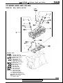
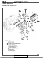
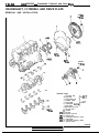
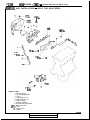
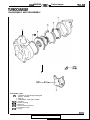
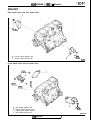
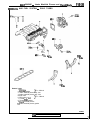
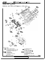
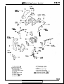
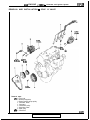
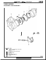
4Gl ENGINE - Front Case and Oil Pump
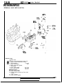
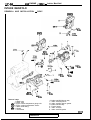
FRONT CASE AND OIL PUMP
REMOVAL AND INSTALLATION
45 Nm
33 ft.lbs.
I
7
Removal steps
eD4 1. Oil filter
2. Drain plug
3. Drain plug gasket
QAI$~C~ 4. Oil pan
5. Oil screen
6. Oil screen gasket
7. Relief plug
8. Gasket
9. Relief spring
10. Relief plunger
+B4 11. Oil seal
12. Front case
13. Front case gasket
14. Oil pump cover
@I) +A4 15. Outer rotor
@I) +A4 16. Inner rotor
lEN0165
TSB Revision
1 IA-40
4Gl ENGINE - Front Case and Oil Puma,
REMOVAL SERVICE POINTS 1
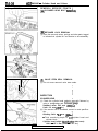
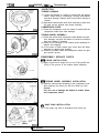
OAo OIL PAN REMOVAL
(1) Knock the special tool deeply between the oil pan and the
cylinder block.
(2) Hitting the side of the special tool, slide the special tool
along the oil pan to remove it.
OBo
OUTER ROTOR / INNER ROTOR REMOVAL
(I) Make alignment marks on the outer and inner rotors for
reference in reassembly.
lEN008t
INSPECTION
.?
OIL PUMP
(1) Check the tip clearance.
Standard value: 0.03 - 0.08 mm (.00?2 - .0031 in.)
(2) Check the side clearance.
Standard value: 0.04 - 0.10 mm (.0016 - .0039 in.)
!
fI
?
?’
(3) Check the body clearance.
Standard value: 0.10 - 0.18 mm I.0039 - .0071 in.)
Limit: 0.35 (.138 in.)
“,
i
:s
P
E
TSB Revision
I
4Gl ENGINE - Front Case and Oil Pump
INSTALLATION SERVICE POINTS
I)A4 INNER ROTOR / OUTER ROTOR INSTALLATION
(1) Install the outer rotor in the same direction as before noting
the mark put at the time of removal. Apply engine oil to the
entire rotor surface.
I
lEN00801
eB4
MD998305 n’
\
CRANKSHAFT FRONT OIL SEAL INSTALLATION
(1) Set the special tool on the crankshaft front end and apply
engine oil to its outer circumference.
(2) Apply a light coat of engine oil to the oil seal lip and then
slide the oil seal down along the special tool by hand until it
touches the front case. Install the oil seal in the front case
using the other special tool.
TSB Revision
4Gl ENGINE - Front Case and Oil Puma
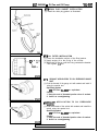
I)c4 O I L P A N I N S T A L L A T I O N
(1) Scrape clean or wire brush all gask{t surfaces removing all
loose material.
(2) Apply a 4 mm (16 in.) diameter beid of sealant to the oil
pan flange.
.F
1
Specified sealant:
Mitsubishi Genuine Part No. ‘%lD970389 or equivai.
lent
(3) The oil pan should be installed within 15 minutes after the
application of sealant.
4 mm (.I 6 in.) diameter
based sealant
Bog,hole
po +on
t
Groove
portion
;
J
I)04 OIL FILTER INSTALLATION
(1) Clean the filter installation surface of the filter bracket.
(2) Apply engine oil to the O-ring of the oil filter.
(3) Screw the oil filter on the bracket until the O-ring contacts
the base. Then tighten one additional turn.
TSB Revision
yl&g
..
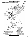
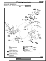
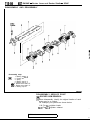
4Gl ENGINE - Piston and Connecting Rod
PISTON AND CONNECTING ROD
REMOVAL AND INSTALLATION
Removal steps
OAo $1 k khecting rod cap
3. Connecting rod bearing
*iI4 4. Piston and connecting rod
5. Connecting rod bearing
eC4 6. Piston ring No. 1
eC4 7. Piston ring No. 2
I)B4 8. Oil ring
oBoeA 9. Piston pin
10. Piston
11. Connecting rod
12. Bolt
‘.
1 EN0245
TSB Revision
IlA-44
4Gl ENGINE - Piston and Connecting Rod
DISASSEMBLY ,SERVlCE POINT6
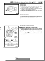
OAo CONNECTING ROD CAP REMOVAL
ylinder No.
(1) Mark the cylinder number on the side of the connecting rod
big end for correct reassembly.
DENOOM
Piston pin setting tool MIT21 6941
7EN042E
Press pin
$Mgg
, Piston pin
h
Front mark
(IBM PISTON PIN REMOVAL
Item No.
Part No.
Description
1
2
3
4
5
6
7
8
9
10
11
MIT310134
MIT310136
MIT310137
MIT310138
MIT310139
MIT310140
MIT310141
MIT310142
M IT48 143
Base
Piston Support
Connecting Rod
Connecting Rod
Connecting Rod
Piston Support
Connecting Rod
Piston Support
Press Pin
Stop Screw
Nut
2 16943
10396
Guide Pin
Guide Pin
Guide Pin
Guide Pin
(2) Select the correct piston support for your applrcatron. (See
above.) Fit the piston support onto the base. Place the base
on the press support blocks.
(3) Insert the press pin through the piston pin hole. Select the
correct connecting rod guide pin. (See above.) Thread the
guide pin onto the threaded portion of the press pin.
(4) Position the piston assembly on the piston support in the
press. With the press pin up as shown in the illustration,
insert the guide pin through the hole in the piston and
through the hole in the piston support.
(5) Press the piston pin out of the assembly.
IMPORTANT: To avoid piston damage,
l
The piston support must seat squarely against the
9
piston.
l Verify that the piston pin will qide through the hole
in the piston support.
(6) Remove the piston pin from the f$ess pin.
1
Connecting rod
de pin
7EN042E
ivision
INSPECTION
PISTON RING
(1) Check for side clearance.
If the limit is exceeded, replace the ring or piston, or both.
5EN0066
Standard value:
0.03 - 0.07 mm (A012 - .0028 h.)
No. 1
0.02 - 0.08 mm (&IO8 - .0024.‘in.)
No. 2
Limit: 0.1 mm (.004 in.)
(2) insert the piston ring into the cylinder bore. Force the ring
down with a piston, the piston crown being in contact with
the ring, to correctly position it at right angles to the cylinder
wall. Then, measure the end gap with a thickne$s gauge.
If the end gap is excessive, replace the piston ring.
Standard value:
0.20 - 0.40 mm (.0079 - .0157 in.)
No. 1
0.20 - 0.35 mm (-0079 - .0138 in.)
No. 2
0.20 - 0.70 mm (.0079 - .0276 in.)
Oil
Limit:
No. 1, No. 2 0.8 mm (.031 in.)
1.0 mm (.038 in.)
Oil
Piston kg
End gap
6EN0548
&llT;E;yFT PlN OIL CLEARANCE (PLASTIC GAUGE
(1) Remove oil from crankshaft pin and connecting rod bearing.
(2) Cut the plastic gauge to the same length as the width of
bearing and place it on a crankshaft pin in parallel with its
axis.
(3) Install the connecting rod cap carefully and tighten the bolts
to specified torque.
(4) Carefully remove the connecting rod cap.
(5) Measure the width of the plastic gauge at its widest part by
using a scale printed on the plastic gauge package.
Standard value: 0.02 - 0.05 mm (.OOOS - AI020 in.)
Limit: 0.1 mm (.004 in.)
1 TSB Revision
I
11 A-46
4Gl ENGINE - Piston and Connecting Rod
REASSEMBLY SERVICE POINTSI)A4 PISTON PIN INSTALLATION ,’
(I) Thread the stop screw and lock nut asiembly into the base.
Fit the correct piston support on the top of the base. Insert
the press pin, threaded end up, into t?re hole in the piston
support until the press pin touches e stop screw.
(2) Using the graduations on the press n, adjust the stop
screw to the correct depth of 49 mm (1.93 in.)
7EN0421
(3) Place the base on the press support blocks.
(4) Slide the piston pin over the threaded end of the press pin,
and thread the correct guide pin up against it.
(5) Coat the piston pin with oil, and with the connecting rod
held in position, slide the guide pin through the piston and
the connecting rod.
(6) Press the piston pin through the connecting rod until the
guide pin contacts the stop screw.
(7) Remove the piston assembly from the base. Remove the
guide pin and the press pin from the assembly.
IMPORTANT: Due to production tolerance variations, it
is necessary to visually inspect t@ piston pin depth
after installation to verify that the piston pin is
centered. Adjust if necessary.
‘*
3
7EN042:
TSB Revision
4Gl ENGINE - Piston and Connecting Rod
*6+ OIL RING INSTALLATION
(1) Fit the oil ring spacer into the piston ring groove.
NOTE
The side rails and spacer may be installed in either direction.
1 EN027;I
Side rail gap
1 EN026E
(2) Install the upper side rail.
To install the side rail, first fit one end of the rail into the
piston groove, then press the remaining portion into
position by finger. See illustration.
Caution
Do not use piston ring expander when installing the
side rail.
(3) Install the lower side rail in the same procedure as
described in step (2).
(4) Make sure that the side rails move smoothly in either
direction.
I)c4 PISTON RING No. 2 / PISTON RING iuo. 1 INSTALLATION
(1) Using piston ring expander, fit No. 2 and then No. 1 piston
ring into position.
NOTE
(1) Note the difference in shape between No.‘l, and No. 2
piston rings.
(2) Install piston rings No. 1 and No. 2 with their side having
marks facing up (on the piston crown side).
7EN045:
Identification mark
stamped
,
I
No. 1
-l
1’
Barrel
type
Identification mark stamped
1
L
Taper type
No. 2
1 EN027t
No. 1
I)D4 PISTON AND CONNECTING ROD ASSEMBLY INSTALLATION
(1) Apply engine oil to the piston surface, piston rings, and oil
ring.
(2) Align the gaps of piston rings and oil ring (side rails and
spacer) as shown in the illustration.
side
No. 2 rinq qap
and spa&gap
6EN054!
TSB Revision
IlA-48
461 ENGINE - Piston and Connecting R o d
Timing belt
c3 side
(3) Rotate crankshaft so that the crank pi^n is on the center of
the cylinder bore.
(4) Use suitable thread protectors on theconnecting rod bolts
before inserting piston and connecting rod assembly into
the cylinder block.
Care must be taken not to nick the crank pin.
(5) Using a suitable piston ring compressor. tool, install the
piston and connecting rod assembly ir#o the cylinder block.
ront mark
1 EN0247
I)E4 CONNECTING ROD CAP INST&LLATION
(1) Verifying the mark made during dis$ssembly, install the
bearing cap to the connecting rod. If the connecting rod is
new with no index mark, make sure th@ the bearing locking
notches come on the same side as-, shown.
e
(2) Make sure that connecting rod big end side clearance
meets the specification.
Standard value: 0.10 - 0.25 mm f.0039 - .00!38 in.)
3
Limit: 0.4 mm (.018 in.)
I)F4
CONNECTING ROD CAP NUT
[NSTALLATION
(1) Since the connecting rod bolts and nuts are torqued using a
new procedure, they should be examined BEFORE reuse. If
the bolt threads are “necked down” the bolts should be
I”
replaced.
Necking can be checked by running a &rt with fingers to the
full length of the bolt’s thread. If the nut does not run down
smoothly the bolt should be replaced.
(2) Install the connecting rod cap on the big end of connecting
rod.
(3) Before installing the nuts the threads-should be oiled with
engine oil.
(4) Install both nuts on each bolt finger tight, then alternately
torque each nut to assemble the cap properly.
(5) Tighten the nuts to 20 Nm (14.5 ft.lbs.) and plus l/4 (90”)
turn.
t
TSB Revision
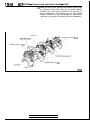
461 ENGINE - Crankshaft, Flywheel and Drive Plate
CRANKSHAFT, FLYWHEEL AND DRIVE PLATE
REMOVAL AND INSTALLATION
., 135.Nm
.Y fths-
11 Nm
8 ft.lbs.
8
Al,
I f
L
19 Nm
l4 fi*‘bfm
184%
3
\
135Nm
- 6 ft.lbk.
53 Nm
38 ft.lbs.
Removal steps
1. Flywheel bolt
For MIT
2. Flywheel
3. Drive plate bolt
4. Adaptor plate
5. Drive plate
6. Adaptor plate
7. Crankshaft bushing
8. Rear plate
9. Bell housing cover
10. Oil seal case
11. Oil seal case gasket
*Cl4 12. Rear oil seal
13. Bearing cap bolt
*C4 14. Bearing cap
#B+ 15. Crankshaft bearing, lower
16. Crankshaft
@B4 17. Crankshaft bearing, upper
#A4 18. Oil pressure switch
19. Cylinder block
1 EN343
1 TSB Revision
I
I
1 IA-50
461 ENGINE - Crankshaft, Flywheel and Drive Plate
rr,
INSPECTION
CRANKSHAFT JOURNAL OIL CLEARANCE (PLASTIC
GAUGE METHOD)
(1) Remove oil from the crankshaft journal and the crankshaft
bearing.
(2) Install the crankshaft.
(3) Cut the plastic gauge to the same length as the width of
bearing and place it on the journal in parallel with its axis.
6EN055C
(4) Install the crankshaft bearing cap carefully and tighten the
bolts to the specified torque.
(5) Carefully remove the crankshaft bearing cap.
(6) Measure the width of the plastic gauge at its widest part by
using a scale printed on the plastic gauge package.
Standard value: 0.02 - 0.05 mm (.OOOS - .0020 in.)
Limit: 0.1 mm (.004 in.)
;
i;
Al
B
0
CYLINDER BLOCK
(1) Using a straightedge and feeler gaugzcheck the block top
surface for warpage. Make sure thagthe surface is free
from gasket chips and other foreignimatters.
Standard value: 0.05 mm (.002 in.)
Limit: 0.1 mm (004 in.)
(2) If the distortion is excessive, correct within the allowable
limit or replace.
Grinding limit: 0.2 mm (.008 in.)
The total resurfacing depth of both cylinder block
and mating cylinder head is 0.2 mm (008 in.) at
$
maximum.
Cylinder block height (When new)?
255.9 - 256.1 mm (10.075 - lO~iO88 in.)
(3) Check cylinder walls for scratches and seizure. If defects
are evident, correct (rebore to an oversize) or replace.
(4) Using cylinder gauge, measure the’ cylinder bore and
cylindricity. If worn badly, correct the cylinder to an oversize
and replace the piston and piston rings. Measure at the
points shown in illustration.
i
Standard value:
75.50 - 75.53 m m
Cylinder I.D.
(2.9724 - 2.9736 in.)
Cylindricity: 0.01 mm (0004 in.) or less
TSB Revisipn
4Gl ENGINE - Crankshaft, Flywheel and Drive Plate
BORING CYLINDER
(1) Oversize pistons to be used should be determined on the
basis of the largest bore cylinder.
Piston size identification
Thrust
direction
6EN055
Identification
Size
0.50 mm (.02 in.) O.S.
0.75 mm (.03 in.) OS.
1 .OO mm (.04 in.) OS.
0.25
0.50
0.75
I-
1 .oo
NOTE
Size mark is stamped on the piston top.
(2) Measure outside diameter of piston to be used. Measure it
in thrust direction as shown.
(3) Based on the measured piston O.D. calculate the boring
I,:“.
finish dimension.
Boring finish dimension = Piston O.D. + (clearance
between piston O.D. and cylinder) - 0.02 mm (.OOOS in.)
(honing margin)
(4) Bore all cylinders to the calculated boring finish dimension.
Caution
To prevent distortion that may result from temperature
rise during honing, bore cylinders, in this order: No. 2
to No. 4 to No. 1 to No. 3.
(5) Hone to the final finish dimension [piston O.D. + clearance
between piston O.D. and cylinder.]
(6) Check the clearance between piston and cylinder.
Clearance between piston and cylinder:
0.02 - 0.04 mm (.OOOS - .0016 in.)
NOTE
When boring cylinders, finish all of four cylinders to the
same oversize, Do not bore only one cylinder to an oversize.
INSTALLATION SERVICE POINTS
*A+ SEALANT APPLICATION TO OIL P R E S S U R E
SWITCH
9EN0094
+B4 CRANKSHAFT BEARING INSTALLATION
Grooveless
lwer bearing
(1) Coat the threads of switch with sealant before installirlg the
switch.
Specified sealant: 3M ATD Part No. 8660 or equivalent
Caution
1. Keep the end of threaded portion clear of sealant.
2. Avoid an overtightening.
Upper bearing
(for No. 1.2.4.5)
Upper and lower bearings
(for No. 3)
(1) No. 1, 2, 4 and 5 upper bearings (cylinder block side) are
provided with oil groove.
(2) No. 1, 2, 4 and 5 lower bearings (cap side) are not provided
with oil groove.
(3) No. 3 bearings are flanged and provided with no groove.
Common bearings are used on the cap side and cylinder
block side.
1 EN027
TSB Revision
11 A-52
401 ENGINE - Crankshaft, Flywheel and Drive Pla$
I)c4 INSTALLATION OF BEARING CAP
(1) Install according to the front mark end cap No.
NO174
Timing
belt side
Cap No.
1 EN017E
(2) After installing the bearing caps, make sure that the
crankshaft turns smoothly and the end play is correct. If the
end play exceeds the limit, replace crankshaft bearings.
Standard value: 0.05 - 0.18 mm (.0020 - .0071 in.)
Limit: 0.3 mm (.012 in.)
1 EN028C
eD4 OIL SEAL INSTALLATION
Oil seal
Oil seal case
1 EN027:
TSB Revision
l.lA-53
4Gl ENGINE - Bracket
BRACKET
REMOVAL AND INSTALLATION
65 Nm
47 ft.lbs.
2
60 Nm
44 ft.1bs.h
36 Nm
26 ft.lbs.
/--+GFL
yy
1
120 Nm
67 ftlbs.
‘\
Removal steps
1. Exhaust pipe support bracket
2. Engine support bracket, front
3. Roll stopper bracket, front
4. Roll stopper bracket, rear
1 EN0347
TSB Revision
I
NOTES
ENGINE
4637
CONTENTS
BRACKET . . . . . . . . . . . . . . . . . . . . . . . . . . . . . . . . . . . . . . . . . . . . . . . . . . . . . . . . . . . .
CRANKSHAFT, FLYWHEEL AND
DRIVE PLATE . . .._..............._...._..............................
CYLINDER HEAD AND VALVES f.......................
EXHAUST MANIFOLD AND
WATER PUMP . . . . . . . . . . . . . . . . . . . . . . . . . . . . . . . . . . . . . . . . . . . . . . . . . . . .
FRONT CASE, OIL PUMP AND OIL PAN . . . . . . . .
FUEL AND EMISSION PARTS . . . . . . . . . . . . . . . . . . . . . . . . . . . .
GENERAL INFORMATION . . . . . . . . . . . . . . . . . . . . . . . . . . . . . . . .
GENERAL SPECIFICATIONS . . . . . . . . . . . . . . . . . . . . . . . . . . . .
62
58
39
32
45
26
‘2
5
GENERATOR AND IGNITION SYSTEM ........ 16
INTAKE MANIFOLD ............................................ 30
PISTON AND CONNECTING ROD .................... 52
ROCKER ARMS AND CAMSHAFT .......... :. ........ 34
SEALANT ................................................................ 12
6
SERVICE SPECIFICATIONS ................................
SPECIAL TOOLS .................................................... 13
THROTTLE BODY ................................................ 28
TIMING BELT ........................................................ 18
TORQUE SPEClklCATlONS .................... /. .......... 10
IIB-2
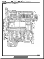
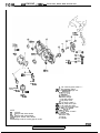
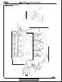
4G3 ENGINE - General Information
GENERAL INFORMATION
ENGINE SECTIONAL VIEW
3ENOO86
1 TSB Revision
I
4G3 ENGINE - General Information
I
pqJp3
3EN0087
\ TSB Revision
IIB-4
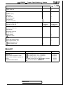
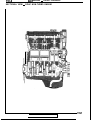
4G3 ENGINE - General Information
JBRICATION SYSTEM
3LUOO20
TSB Revision
4G3 ENGINE - General Specifications
ptgpg
GENERAL SPECIFICATIONS
Description
Specifications
Type
Number of cylinders
Combustion chamber
Total displacement cm3 (cu. in.)
mm (in.)
Cylinder bore
Piston stroke
mm (in.)
Compression ratio
Valve timing:
( 1: camshaft identification mark
Intake valve
Opens
Closes
Exhaust valve
Opens
Closes
Lubrication system
Oil pump type
Cooling system
Water pump type
EGR type
Injector type and number
Injector identification mark
Fuel regulated pressure
kPa (psi)
Throttle bore
mm (in.)
Throttle position sensor
Closed throttle position switch
In-line OHV, SOHC
4
Compact type
1.755 (107.10)
80.6 (3.17)
86 (3.39)
9.0
: ““:’ -_: .: .///,.’
.I-.: :_
(AR)
20” BTDC
52” ATDC
55” BBDC
17” ATDC
Pressure feed, full-flow filtration
Involute gear type
Water-cooled forced circulation
Centrifugal impeller type
Single type
Electromagnetic 4
N210H
335 (47.6)
50 (1.969)
Variable resistor type
Contact type, within idle speed control motor
.
I .,
IIB-6
4G3 ENGINE - Service Specifications
7
SERVICE SPECIFICATIONS
mm (in.)
Limit
Standard
Cylinder head
Flatness of gasket surface
Grinding limit of gasket surface
* Total resurfacing depth of both cylinder head
and cylinder block
Overall height
Oversize rework dimensions of valve
guide hole
(both intake and exhaust)
0.05 (002)
0.25 (.OlO)
0.50 (020)
Oversize rework dimensions of intake valve
seat ring hole
0.30 (012)
0.60 (024)
Oversize rework dimensions of exhaust
valve seat ring hole
0.30 (012)
0.60 (.024)
37.30 -37.33 (1.4685 - 1.4697)
37.60 - 37.63 (1.4803 - 1.4815)
Camshaft
Cam height
Fuel pump driving cam diameter
Journal diameter
Oil clearance
35.91 (1.4138)
40 (1.57)
33.94 - 33.95 (1.3362 - 1.3366)
0.05 - 0.09 (0020 - .0035)
Rocker arm
I.D.
Rocker arm-to-shaft clearance
Rocker shaft
O.D.
Overall length
Intake
Exhaust
0.05 (.0020)
t
0.2 (.008)
“0.2 (008)
88.4 - 88.6 (3.480 - 3.4881
i
13.05- 13.07 (.5138-.5146)
13.25 - 12.27 (5217 - 95224)
13.50- 13.52 (.5315-.5323)
43.30 - 43.33 (1.7047 - 1.7059)
43.60-43.63(1.7165-1.7177)
.I
<
35.41 (1.3941)
39.5 (1.555)
i
c
_
18.91 - 18.93 (.7444 - .7453)
0.01 - 0.04 (.0004 - .0016)
0.1 (.004)
18.89- 18.90 (7437 - .7440)
365.5 (14.035)
350.0 (13.780)
1 TSB Revision
1
463 ENGINE - Service Specifications
mm (in.)
Standard
Limit
I c’:,; ,.
*‘:’ ;, :,i :; . .
.-y >,-;
,.
Valve
Overall length
Intake
Exhaust
Stem diameter
Intake
Exhaust
Face angle
Thickness of valve
head (margin)
Intake
Exhaust
Stem-to-guide
clearance
Intake
Exhaust
1.2 (.047)
1.5 (.059)
0.7 (.028)
1 .o i.039)
0.03 - 0.06 (0012 - .0024)
0.05 - 0.09 (.0020 - .0035)
0.10 (.0039)
0.15 c.qaq$l) ,
Valve spring
Free height
Load/installed height
Out-of-squareness
49.2 (1.937)
31 O/37.3 (68/l .469)
Max. 2”
48.2 (1.896)
Valve guide
Overall length
Intake
Exhaust
I.D.
O.D.
Service size
Press-in temperature
Valve seat
Seat angle
Valve contact width
Sinkage
service size
98.2 (3.866)
95.5 (3.760)
7.96-7.98(.313-.314)
7.93 - 7.95 (.312 - ,313)
45” - 45”30’
N/mm (Ibs./in.)
4”
,!
44 (1.73)
48 (1.89)
7.2 -7.25 (.2835 - .2854)
13.06-13.07(.5142-.5146)
0.05 (.002), 0.25 (.Ol), 0.50 (.02) oversize
Room temperature
4
43”30’ - 44”
0.9 - 1.3 (.035 - .051)
0 . 2 (.008)
0.3 (.OlZ), 0.6 (024) oversize
1 TSB Revision
463 ENGINE - Service SDecifications
mm (in.)
Standard
Limit
Silent shaft
Journal diameter
Right(front)
(rear)
Left (front)
(rear)
Oil clearance
Right(front)
(rear)
Left Ifrar$)
r
0.02
0.05
0.02
0.05
Piston
O.D.
Piston-to-cylinder clearance
Service size
80.57 - 80.60 (3.1720 - 3.1732)
0.02 - 0.04 (.0008 - .0016)
0.25 (.Ol), 0.50 (.02), 0.75 (.03), 1 .OO (.04) oversize
38.96 - 38.98 (1.5339 - 1.5346)
35.95 - 35.97 (1.4154 - 1.4161)
18.47 - 18.48 (.7272 - .7276)
35.95 - 35.97 (I .4154- 1.4161)
-
0.06 (.0008
0.09 (.0020
0.05 (.0008
0.09 (.0020
- .0024)
- .0035)
- .0020)
- .0035)
Piston ring
End gap
No. 1 ring
No. 2 ring
Oil ring
Ring-to-ring groove clearance
No. 1 ring
No. 2 ring
Service size
0.05 - 0.09 (.0020 - .0035)
0.02 - 0.06 (.0008 - .0024)
0.25 (.Ol), 0.50 (.02), 0.75 (.03), 1 .OO (.04) oversize
Piston pin
O.D.
Press-in load N (Ibs.)
Press-in temperature
19.00 - 19.01 (.7480 - .7484)
5,000 - 15,000 (I, 102 - 3,307)
Room temperature
Connecting rod
Big end center-to small end center length
Bend
Twist
Big end side clearance
153.6 - 153.7 (6.047 - 6.051)
0.05 (.0020)
0.1 (.004)
0.10 - 0.25 (.0039 - .0098)
0.30-0.45(.0118-.0177)
0.20- 0.35 (.0079 - .0138)
0.20 - 0.70 LOO79 - .0276)
TSB Revision
0.8 (.031)
0.8 (.031)
1 .o (.039)
0.4 (.OI 6)
463 ENGINE - Service Specifications
Crankshaft
End play
Journal O.D.
Pin O.D.
Out-of-roundness and taper of journal
and pin
Oil clearance of journal
Oil clearance of pin
Journal undersize
0.25 (.OlO) U.S.
0.50 (.020) U.S.
0.75 (.030) U.S.
Pin undersize
0.25 (.OlO) U.S.
0.50 (020) U.S.
0.75 (.030) U.S.
Standard
Limit
0.05-0.18(.0020-.0071)
57 (2.24)
45 (1.77)
Within 0.01 (0004)
0.3 (;012~
:, .’ ,/
*
,‘/~
0.02-0.05 (.0008- .0020)
0.02 - 0.05 (.0008 - .0020)
0.10 (.0039)
0.10 (.0039)
56.74 - 56.75 (2.2339 - 2.2342)
56.49 - 56.50 (2.2240 - 2.2244)
56.24-56.25 (2.2142-2.2146)
44.74-44.75(1.7614-1.7618)
44.49 -44.50 (1.7516 - 1.7520)
44.24-44.25 (1.7417 - 1.7421)
Cylinder block
I.D.
Flatness of gasket surface
Grinding limit of gasket surface
* Total resurfacing depth of both cylinder block
and cylinder head
Dverall height
285.1 -285.3(11.224-11.232)
3il pump
side clearance
Drive gear
Driven gear
0.08-0.14 (0031 - .0055)
0.06 - 0.12 (0024 - .0047)
Irive belt deflection
Jew belt
Jsed belt
6.5-8(.26-.31)
8 - 11 (31 - .43)
njector
:oil resistance CR
I3 - 16 at 20°C (68°F)
‘hrottle position sensor
3esistance
kfi
3.5-6.5
dle speed control motor
:oil resistance IR
5 - 35 at 20°C (68°F)
dle speed control motor position sensor
jesistance
kfi
4-6
80.60 - 80.63 (3.1732 - 3.1744)
0.05 (.002)
TSB Revision
0. i (IboT$
*0.2 (068).
-.
IIB-10
4G3 ENGINE - Torque Specifications
TORQUE SPECIFICATIONS
Nm
ft.lbs.
Generator and ignition system
W a t e rpump
pulley bolt
Generator brace bolt
Generator brace mounting bolt
Generator pivot nut
Damper pulley bolt
Crankshaft pulley bolt
Spark plug
Distributor mounting nut
9
I4
19
23
17
17
25
12
7
IO
14
I7
12
12
18
9
Timing belt
Tensioner bolt and nut
Oil pump
sprocket
nut
Crankshaft sprocket bolt
Tensioner “B” bolt
Engine support bracket, left
Camshaft sprocket bolt
26
37
120
19
36
90
Fuel and emission parts
Throttle body mounting bolts
Fuel rail mounting bolts
Fuel pressure
regulator
bolts
19
12
9
EGR valve mounting bolts
22
16
Throttle body
Throttle position sensor attaching bolts
2.0
1.4
Intake manifold bolt and nut
11
30
19
18
18
I8
22
18
8
22
14
13
13
I3
16
I3
Exhaust manifold and water pump
gauge
Oil level
guide bolt
Exhaust manifold cover “A” bolt
Exhaust manifold cover “A” and “B” mounting bolt
Exhaust manifold cover “B” bolt
Exhaust manifold nut
Water inlet pipe bolt
Water pump bolt
14
30
9
24
18
14
14
Intake manifold
Engine coolant temperature gauge unit
Engine coolant temperature sensor
Water outlet fitting bolt
Intake manifold plenum stay bolt
Intake manifold plenum bolt and nut
Thermostat housing bolt and nut
Intake manifold stay bolt
1 TSB Revision
,
19
27
87
I4
26
65
.,:
i
9
t
14
9
7
10
22
7
17
I3
10
IO
4G3 ENGINE - Torque Specifications
Rocker cover bolt
Camshaft bearing cap bolt (M8)
Camshaft bearin
Oil pressure gauge unit
Oil filter bracket
Oil pan drain plug
Oil pan bolt
Oil screen nut
Oil pump cover bolt
Oil pump driven gear bolt
Oil relief valve plug
3ear plate bolt
3ell housing cover bolt
3il seal case bolt
3earing cap bolt
53
38
3racket
Exhaust pipe support bracket
3011 stopper bracket, front
3011 stopper bracket, rear
Ingine support bracket, right
36
65
120
65
26
47
87
47
[ TSB Revision
I
IIB-12
4G3 ENGINE - Sealant
SEALANT
Specified sealant
Engine coolant temperature sensor
Engine coolant temperature gauge unit
Semi-circular packing
Oil pan
Oil pressure gauge unit
Oil pressure switch
3M Nut Locking Part No. 4171 or equivalent
3M ATD Part No. 8660 or equivalent
3M ATD Part No. 8660 or equivalent
MITSUBISHI GENUINE Part
MD970389 or equivalent
3M ATD Part No. 8660 or equivalent
3M ATD Part No. 8660 or equivalent
~‘Ouantity
ps
ps
As
ks
As required
%s required
T
TSB Revision
required
required
required
required
1
463 ENGINE - Special Tools
SPECIAL TOOLS
r00i
Number and
tool name
Supersession
MB990767
Lns”, yo!; holder
MB990767-01
Holdingcamshaft sprocket when loosening
Use with MIT308239 or torquing bolt.
Application
.
MD9987 19
MD99801 1
Crankshaft rear
oil seal installer
MD99801 l-01
Use with
M B990938-01
Installation of crankshaft rear oil seal
MD9981 28
MD9981 84-01
Piston pin setting
tool
Removal and Installation of piston pin
MD998280
Silent shaft
bearing installer
MD998280-01
Use with MIT21 5869
Installation of silent shaft bearing front
MD998282
Silent shaft
bearing puller
M D998282-01
Use with MIT304204
Removal of silent shaft bearing front
MD998283
Silent shaft
bearing puller
M D998283-01
Use with MIT304204
Removal of silent shaft bearing rear
MD998285
Crankshaft front
oil seal guide
MD998285-01
Installation of crankshaft front oil seal
M 0998286
Silent shaft
bearing installer
MD998286-01
Installation of silent shaft bearing rear
MD998304
Crankshaft front
oil seal installer
M D998304-0 I
Installation of crankshaft front oil seal
@
0
ff!f
/
] TSB Revision
IIB-14
463 ENGINE - Special Tools
Leak-down tester
Air bleed wire
MD998713
Camshaft oil seal
installer
M D9987 13-O 1
Installation of camshaft oil seal
MD998719
Pulley holding
pins (2)
M IT308239
Holding camshaft sprocket when loosening
or torquing bolt
_
M D998727
Oil pan remover
M D998728
Valve stem seal
installer
Removal of oil pan
MD998728-01
1 TSB Revision
Installation of valve stem seal
I
463 ENGINE - Special Tools
Removal of crankshaft sprocket
1 TSB Revision
IIB-16
4G3 ENGINE - Generator and Ignition System
GENERATOR AND IGNITION SYSTEM
REMOVAL AND INSTALLATION
25 Nm
- 18 ft.lbs.
23 Nm
@- 17 ft.lbs.
14 ilm
10 ft.lbs.
I
19 Nm
14 ft.lbs.
7
9Nm
7 ftlbs.
12 Nm
9 ft.lbs.
17’Nm
12 ft.lbs.
17 Nm
12 ft.lbs.
Removal steps
+B4 1. Drive belt
2. Water pump pulley
3. Generator brace
4. Generator
5. Damper pulley
6. Adapter
7. Crankshaft pulley
8. Spark plug cable
9. Spark plug
10. Distributor
11. O-ring
3EN0212
4G3 ENGINE - Generator and Ignition System
INSTALLATION SERVICE POINTS
I)Ag DISTRIBUTOR INSTALLATION
(1) Turn the crankshaft so that the I&. 1 cylinder is at to; dead
center.
(2) Align the distributor housing and gear mating marks.
3EN022~
(3) Install the distributor to the engine while aligning the fine
cut (groove or projection) of the distributor’s installation
flange with the center of the distributor installation stud.
I)B4 DRIVE BELT TENSION ADJUSTMENT
pump
(1) Move the generator to give greater tension to the belt so
L
that the specified deflection is obtained.
Standard value:
New belt: 6.5 - 8 mm (.26- .31 in.)
Used belt: 8 -11 mm (.31- .43 in.)
Crankshaft pulley
$F&j
3EN0226
Water pump pulley
Generato
Crankshaft pulley
6EN059f i
Or using a tension gauge, adjust the tension to the standard
value.
5
Standard value:
New belt: 500 - 700 N (110 - 154 Ibs.)
Used belt: 400 N (88 Ibs.)
(3) Tighten the generator brace bolt.
(4) Tighten the nut for the generator pivot bolt.
IIB-18
4G3 ENGINE - Timing Belt
TIMING BELT
REMOVAL AND INSTALLATION
36Nm l5
26 ft.lbs.
I
37 Nm
27 ft.lbs.
12
I
13
I
Removal steps
1. Timing belt front upper cover
2. Timing belt front lower cover
(IAO eH4 3. Timing belt
#G4 4. Tensioner
#G4 5. Tensioner spring
461) +F4 6. Oil pump sprocket
(I$$ +E4 7. Crankshaft bolt
8. Crankshaft sprocket
9. Flange
10. Tensioner “B”
OEo *II4 11. Timing belt “6”
(IFI) eC4 12. Silent shaft sprocket
*B4 13. Spacer
14. Crankshaft sprocket “B”
SO
15. Engine support bracket, left
(IHO #A4 16. Camshaft sprocket bolt
17. Camshaft sprocket
18. Timing belt under upper cover
19. Timing belt under lower cover
_.
TSB Revision
3EN0213
463 ENGINE - Timing Belt
REMOVAL SERVICE POINTS
qA0 TIMING BELT REMOVAL
(1) Mark the belt running direction for reference -in reihstallation.
aB0 OIL PUMP SPROCKET REMOVAL
(1) Remove the plug on the left side of the cylinder block.
(2) Insert a Phillips screwdriver [shank diameter 8 mm (31 in.)]
to block the left silent shaft.
(3) Remove the nuts.
(4) Remove the oil pump sprocket.
@r) CRANKSHAFT BOLT LOOSENING
(1) Using the special tool, hold the drive plate or flywheel.
(2) Remove the crankshaft bolt.
I
\t
lEN03261
(IDO CRANKSHAFT SPROCKET REMOVAL
3EN021
(IEI) TIMING BELT “B” REMOVAL
(1) Mark the belt running direction for reference in reinstallation.
TSB Revision
1
IIB-20
4G3 ENGINE - Timing B e l t
OF0
SILENT SHAFT SPROCKET REMOVAL
*i -,
OGo
CRANKSHAFT SPROCKET “B’ REMOVAL
QHo CAMSHAFT SPROCKET BOLT LOOSENING
INSPECTION
-
\
000 00B
&
8EN006E
(2)
(3)
(4)
(5)
Cracks
B
TIMING BELT / TIMING BELT “B”
ditions exist.
Replace belt if any of the following
ide is glossy without
(1) Hardening of back rubber - the ba
resilience and leaves no indent whe pressed with fingerk
nail.
4
\
1 EN024E
TSB Revision
Cracks
Cracks
Cracks
Cracks
on rubber back
or peeling of canvas
on rib root
on belt sides
463 ENGINE - Timing Belt
(6) Abnormal wear of belt sides. The sides are normal
)’ if they
are sharp as if cut by a knife.
Rounded edge
/
Abnormal wear
(Fluffy strand)
8EN0067
(7) Abnormal wear in teeth
(8) Missing tooth
Rubber exposed
Tooth missing
and canvas
8EN006E
INSTALLATION SERVICE POINTS
I)A4 CAMSHAFT SPROCKET BOLT INSTALLATION,
#B4 SPACER INSTALLATION
(1) Install the spacer with the chamfered end toward the oil
seal.
I)c4 SILENT SHAFT SPROCKET INSTALLATION
1 TSB Revision
11 B-22
4G3 ENGINE - Timing Belt
I)04 TIMING BELT “B” INSTALLABON
(1) Align the timing marks on the crankshaft sprocket “B” and
silent shaft sprocket with the marks on the front case
respectively.
(2) Install the timing belt “B” on the crankshaft sprocket “B”
and silent shaft sprocket. There should be no slack on the
tension side.
(3) Make sure that the relationship between the tensioner
pulley center and the bolt center’ is as shown in the
illustration.
(4) Move the tensioner “B” in the direction of arrow while
lifting with a finger to give a sufficient tension to the tension
side of timing belt. In this condition, tighten the bolt to
secure tensioner “B”. When the bolt is tightened, use care
to prevent the shaft from turning together. If the shaft is
turned together, the belt will be overtensioned.
c
(5) Check to ensure that the timing marks on the sprockets and
front case are in alignment.
(6) Press with index finger the center of span on the tension
side of timing belt “B”. The belt must deflect 5 to 7 mm
(20 to 28 in.).
I)E4
CRANKSHAFT BOLT TIGHTEifING
(1) Using the special tool, hold the drive plate or flywheel.
(2) Install the crankshaft bolt.
I
$
TSB Revision
463 ENGINE - Timinn Belt
IT&23
I)F4 OIL PUMP SPROCKET INSTALLATION
Y--l
Screwdriver
6R? ” ’ ”
(1) Insert a Phillips screwdriver [shank diameter 8 mm (31 in.)]
through the plug hole on the left side of the cylinder block to
block the left silent shaft.
(2) Install the oil pump sprocket.
(3) Tighten the nuts to the specified torque.
3EN0231
I)Gg
TENSIONER / TENSIONER SPRING INSTALLATION
(1) Hook the tensioner spring ends to the water pump body
and tensioner bracket.
3EN017
(2) Move the tensioner fully toward the water pump and
tighten the nut and bolt.
I)H4 TIMING BELT INSTALLATION
(I) Align the timing marks on the camshaft sprocket and
crankshaft sprocket with their timing marks.
3EN017t
TSB Revision
11 B-24
4G3 ENGINE - Timing Belt
(2) Align the timing mark on the oil pump sprocket with its
mating mark.
(3) Remove the plug on the cylinder block and insert a Phillips
screwdriver [shank diameter 8 mm (.31 in.)] through the
hole. If it can be inserted as deep ‘8s 60 mm (2.4 in.) or
more, the timing marks are correctly *lioned. If the inserted
depth is only 20 to 25 mm (8 to 1 .Odn.), turn the oil pump
sprocket one turn and realign the timing marks. Then check
to ensure that the screwdriver can be inserted 60 mm (2.4
in.) or more. Keep the screwdriver inserted until installation
of the timing belt is finished.
(4) Install the timing belt on the crankshaft sprocket, oil pump
sprocket and camshaft sprocket in t&t order. There should
be no slack on the tension side.
(5) Loosen the tensioner mounting bol) and nut.
z!
:i
45
(6) Turn the crankshaft clockwise by t\;ivo teeth of camshaft
sprocket (or crankshaft sprocket).
(7‘) Apply force to the tensioner in the direction shown by arrow
@ to make the belt engage completely with each sprocket.
TSB Revision
4G3 ENGINE - Timing Belt
(8) Tighten the tensioner attaching nut, then tighten ‘the
tensioner attaching bolt.
Caution
If the bolt is tightened first, tensioner turns as the bolt
is tightened, resulting in an excessive belt tension.
(9) Hold the center of the tension side span of the timing belt
(between the camshaft and oil pump sprockets) between
your thumb and index finger as shown. Then, make sure
that the clearance between the belt back surface and cover
is standard value.
Standard value: 12 mm (.47 in.)
1 TSB Revision
I
11 B-26
4G3 ENGINE - Fuel and Emission Parts
FUEL AND EMISSION PARTS
REMOVAL AND INSTALLATION
-
12 Nm
9 ft.lbs.
‘2
4
I
;.:
L
.
3
19 Nm
14ftJbs.
22 Nm
16 ft.lbs.
Removal steps
1. Throttle body assembly
2. Gasket
3. Injector and fuel rail
#B4 4. Fuel pressure regulator
5. O-ring
6. Fuel rail
7. Insulator
8. Insulator
*A4 9. Injector
10. G-ring
11. Wornmet
3EN0150
TSB Revision
4G3 ENGINE - Fuel and Emission Parts
INSPECTION
Yrm7
. . -’
,.
x,r,
INJECTORS
(1) Using an ohmmeter (circuit tester), test for con&uity
between terminals of injector; the circuit should be closed.
If failure is detected, replace the injector.
Standard value: 13 - 16 n at 20°C (68°F)
6FU192C
EGR VALVE
(1) Check EGR valve for sticking or carbon deposits.
If such conditions exist clean or replace EGR valve.
(2) Connect a hand vacuum pump to the nipple of EGR valve
and plug the other nipple.
(3) Apply a vacuum of 500 mm Hg (19.7 in.Hg) to make sure
that vacuum is maintained. If there is a leak, replace the
EGR valve.
In addition, check the valve for its opening and closing
motion by applying and removing vacuum.
6EM038
INSTALLATION SERVICE POINTS
I)A4
INJECTOR INSTALLATION
(1) Before installing an injector, the rubber O-ring must be
lubricated with. a drop of clean engine oil to aid in
installation.
(2) Install injector top end into the fuel pipe. Be careful not to
damage O-ring during installation.
3EN015;
r)64 FUEL PRESSURE REGULATOR INSTALLATION
(1) Before installing the pressure regulator, the O-ring must be
lubricated with a drop of clean engine oil to aid in
installation.
0-rinb
6FUO714
TSB Revision
11 B-28
4G3 ENGINE - Throttle Body
THROTTLE BODY
DISASSEMBLY AND REASSEMBLY
Disassembly steps
(I$! #A4 1. Throttle position sensor
2. Idle speed control motor
3. Throttle valve set screw
4. Throttle body
OBO
6FU1292
DISASSEMBLY SERVICE POINTS
(IAI) THRO-ITLE POSITION SENSOR AND IDLE SPEED
CONTROL MOTOR REMOVAL(1) Do not disassemble the sensor an8 motor.
(2) Do not immerse in solvent the sensor and motor.
Clean them with shop towel.
a:
r
1 TSB Revision
4G3 ENGINE - Throttle Bodv
QBo THROlTLE BODY REMOVAL
(1) Do not remove the throttle valve
(2) Check if the vacuum port or b&sage is clog&~& ‘&e
compressed air to clean the vacuum passage.
Throttle position
sensor power supply
\
Ground
/
REASSEMBLY SERVICE POINT
I)A4 THROlTLE POSITION SENSOR INSTALLATION
(1) Check correct installation of the throttle position sensor.
While moving the throttle lever in both open and close
directions, check to see that resistance between terminals
(ij and @ or @ and @ changes. If resistance changes
smoothly, the throttle position sensor has been installed
correctly.
Throttle poskion
View P
sensor output
Throttle position
sensor connector
7FU053E
P
1 EN024E
TSB Revision
11 B-30
463 ENGINE - Intake Manifold
INTAKE MANIFOLD
REMOVAL AND INSTALLATION
19 Nm
14ft.lbs.
18 Nm
13 ftlbs.
1
5
I
18N‘m
13 ft.lbs.
22’Nm
16 ftlbs.
Removal steps
1. Water hose “A”
2. Water hose “B”
eB4 3. Engine coolant temperature gauge unit
#A4 4. Engine coolant temperature sensor
5. Water outlet fitting
6. Water outlet fitting gasket
7. Thermostat
8. Intake manifold plenum stay
9. Intake manifold plenum
IO. Intake manifold plenum gasket
11. Intake manifold stay
12. Engine hanger
13. Thermostat housing
14. Intake manifold
15. Intake manifold gasket
3EN0154
TSB Revision
463 ENGINE - Intake Manifold
INSTALLATION SERVICE POlNTS
I)A4 SEALANT APPLICATION TO EyGlNE Coo&ANT
TEMPERATURE SENSOR
Specified sealant:
3M Nut Locking Part No. 4171 or equivalent
ZEN0219
r)64 SEALANT APPLICATION TO ENGINE COOLANT
TEMPERATURE GAUGE UNIT
Specified sealant:
3M ATD Part No. 8660 or equivalent
Sealant
9EN009
TS8 Revision
11 B-32
463 ENGINE - Exhaust Manifold and Water Pump
EXHAUST MANIFOLD AND WATER PUMP
REMOVAL AND INSTALLATION
30 Nm
14 Nm
10 ft.lbs.
14 Nm
10 ft.lbs.
Removal steps
1. Oil level gauge
2. Oil level gauge guide
3. O-ring
4. Exhaust manifold cover “A”
5. Engine hanger
6. Exhaust manifold
7. Exhaust manifold gasket
8. Exhaust manifold cover “B”
#A4 9. Water inlet pipe
10. O-ring
11. Water pump
12. Water pump gasket
3EN0222
TSB Revision
4G3
O-ring
ENGINE - Exhaust Manifold and Water Pump
1 INSTALLATION SERVICE POINT
Water pump
\
I)A4
WATER INLET PIPE INSTALLATION
(with water) to facilitate assembly.” -’
(1) Wet the 0- ring
.
Caution
Keep the O-ring free of oil or grease
JE
Water! inlet pipe
6EN059
TSB Revision
I
IIB-34
/
4G3 ENGINE - Rocker Arms and Camshaft
ROCKER ARMS AND CAMSHAFT
REMOVAL AND INSTALLATION
20 Nm
14 ft.lbs.
11 Nm
8 ft.lbs. +
6
Removal steps
1. Breather hose
2. P.C.V. hose
3. Oil seal
4. Rocker cover
5. Gasket
6. Rocker arm and rocker shaft
7. Rear camshaft bearing cap
8. Rocker arm
+E4 9. Wave washer
*DC 10. Camshaft bearing cap No. 4
11. Rocker shaft spring
eD4 12. Camshaft bearing cap No. 3
+D4 13. Camshaft bearing cap No. 2
#C4 14. Right rocker shaft
eC4 15. Left rocker shaft
16. Front bearing cap
6Ab MI 17. Lash adiuster
’ ’ iA4 il. ~S+;~;tular packing
eF4 20: Camshaft oil seal
3EN0156
TSB Revision
4G3 ENGINE - Rocker Arms and Camshaft:
REMOVAL SERVICE POINT ’
QAQ
ROCKER ARM AND ROCKkR SHAFT REMOVAL
(1) Mark lash adjusters for installation in the same position.
(2) Remove the lash adjuster holders and the lash adjusters.
INSPECTION
CAMSHAFT
(1) Measure the cam height.
Standard value: 35.91 mm (j.4138 in.)
Limit: 35.41 mm (1.3941 in.)
ROCKER ARM
(1) Visually check the roller and replace if dent, damage, or
seizure is evident.
(2) Check roller for smooth rotation. Replace if it is binding or
there is an excessive play.
(3) Check the inside diameter and replace the rocker arm if
damage or seizure is observed.
7ENO06
LASH ADJUSTER LEAK DOWN TEST
Caution
1. The lash adjuster is a precision part. Keep it free from
dust and other foreign matters.
2. Do not disassemble lash adjuster.
3. When cleaning lash adjuster: use clean diesel fuel only.
TSB Revision
11 B-36
463 ENGINE - Rocker Arms and Camshaft
(1) Immerse the lash adjuster in cleati diesel fuel.
(2) While lightly pushing down inner steel ball using a small
wire, move the plunger up and do9 four or five times to
bleed air.
Use of the Retainer facilitates the aitbleeding of the rocker
arm mounted type lash adjuster. i
(3) Remove the small wire and press thdplunger. If the plunger
is hard to be pushed in, the lash ad&ster is normal. If the
plunger can be pushed in all the wayreadily, bleed the lash
”
adjuster again and test again.
If the plunger is still loose, replace the lash adjuster.
Caution
Upon completion of air bleeding, hold the lash adjuster
upright to prevent inside diesel fuel from spilling.
6EN057C
Division = 1 mm t.04 in.)
(4) After air bleeding, set the lash adjuster on the special tool
(Leak down tester MD998440).
(5) After the plunger has gone down somewhat 0.2 - 0.5 mm
(.008 - 020 in.), measure time taken “for it to go down 1 mm
(.04 in.). Replace if the measured time is out of specification.
Standard value: 4 - 20 seconds / 1 mm (.04 in.)
[Diesel fuel at 15 - 20°C (59 - 68“F)]
7EN043
INSTALLATION SERVICE POINTS
Apply sealant
‘&iii
:. : .:i.:i :.:. : .: .:.
I)A4
SEMI-CIRCULAR PACKING INSTALLATION
(1) Apply specified sealant to the portions indicated in the
illustration.
Specified sealant:
3M ATD Part No. 8660 or equivalent
DEN005:
IOmm
Semi-circular
Cylinder’head
’
’
3EN004L
TSB Revision
-
4G3 ENGINE - Rocker Arms and Camshaft
#B4 LASH ADJUSTER IiUSTALLATlON
(1) Dip the lash adjuster in clean diesel fuel.
(2) While using a small wire to lightly press the check ball
downward, move the plunger up and down four or five
times to bleed out the air.
6EN0421
MD99?443-01
(3) Insert the lash adjuster to the rocker arm, being careful not
to spill the diesel fuel. Then use the special tool to prevent
the lash adjuster from falling while installing the rocker arm
and shaft assembly to the cylinder head.
Lash adjister
7EN017,
I)c4 ROCKER SHAFT INSTALLATION
(1) Install the rocker shafts with notches up and toward the
front bearing cap.
(2) The overall length of the left (intake) rocker shaft is 356.5
mm (14.04 in.); that of right (exhaust) rocker shaft is 350
mm (13.78 in.).
Rocker shaft
for exhaust
Camshaft
for intake
3EN019’
Front mark
/
i!if
0
0
No. 2
Rocker cover
attaching
bolt hole
Cap No.
16
/
I)D4 CAMSHAFT BEARING CAP IDENTIFICATION
0
0
No. 3
No. 4
3EN0093
TSB Revision
11 B-38
4G3 ENGINE - Rocker Arms and Camshaft
+E4 WAVE WASHER INSTALLATIdN
Install the wave washer in correct ‘direction as shown.
Wave washer
I
Wave washer
3EN0081
eF+ CAMSHAFT OIL SEAL INSTALLATION
1 TSB Revision
4G3 ENGINE - Cylinder Head and Valves
CYLINDER HEAD AND VALVES
REMOVAL AND INSTALLATION
2
Removal steps
(IA~J *E4 1. Cylinder head bolt
2. Cylinder head assembly
+ll4 3. Cylinder head gasket
OBrJ eC4 4. Retainer lock
5. Valve spring retainer
I)B4 6. Valve spring
7. Intake valve
(IBI) I)CC 8. Retainer lock
9. Valve spring retainer
I)B4 10. Valve spring
11. Exhaust valve
(IQ) I)A4 12. Valve stem seal
13. Valve spring seat
OCrJ I)A4 14. Valve stem seal
15. Valve spring seat
16. Intake valve guide
17. Exhaust valve guide
18. Intake valve seat
19. Exhaust valve seat
20. Cylinder head
3EN0196
TSB Revision
IIB-40
463 ENGINE - Cylinder Head and Valves
REMOVAL SERVICE POINTS :
OAr)
CYLINDER HEAD BOLT REMqVAL
(1) Using the special tool, loosen the cylinder head bolts
Loosen evenly, little by little.
3EN0185
@s> RETAINER LOCK REMOVAL
(1) Store removed valves, springs and other parts, tagged to
indicate their cylinder No. and location to aid reassembly.
@I) VALVE STEM SEAL REMOVAL
(1) Do not reuse removed valve stem seals.
INSPECTION
3EN018t
A -4,
3EN016:
L
1:
CYLINDER HEAD
(1) Check the cylinder head gasket su:iface for flatness by
using a straightedge and thickness <gauge.
Standard value: 0.05 mm (.0020 In.)
Limit: 0.2 mm (.008 in.)
(2) If the service limit is exceeded, correct to meet the
specification.
Grinding limit: “0.2 mm (.008 in,)
Total resurfacing depth of both cylinder head and
cylinder block
Cylinder head height (Specification when new):
88.4 - 88.6 mm (3.480 - 3.488 in.)
4G3 ENGINE - Cylinder Head and’valves
VALVE
(1) Check the valve face for correct contact. If incorrect, reface
using a valve refacer. Valve should make a uniform contact
with the seat at the center of valve face.
(2) If the margin is smaller than the service limit, replace the
I
,’ I
valve.
n
Standard value:
1.2 mm (047 in.)
Intake
1.5 mm (.059 in.)
Exhaust
I
6EN054i
!
Free height
1 EN0264
Limit:
0.7 mm (028 in.)
Intake
1.0 mm (039 in.)
Exhaust
VALVE SPRING
(1) Measure the free height of the spring and, if it is smaller
than the limit, replace.
Standard value: 49.2 mm (1.937 in.)
Limit: 48.2 mm (1.898 in.)
(2) Measure the squareness of the spring and, if the limit is
exceeded, replace.
Standard value: 2” or less
Limit: 4”
VALVE GUIDE
(1) Measure the clearance between the valve guide and valve
stem. If the limit is exceeded, replace the valve guide or
valve, or both.
Standard value:
0.03 - 0.06 mm (0012 - .0024 in.)
Intake
0.05 - 0.09 mm (.0020 - .0035 in.)
Exhaust
Glide I.D.
Limit:
Intake
Exhaust
1 EN0279
Guide O.D.
0.10 mm (0039 in.)
0.15 mm (.0059 in.)
VALVE SEAT RECONDITIONING PROCEDURE
(1) Before correcting the valve seat, check for clearance
between the valve guide and valve and, if necessary,
replace the valve guide.
(2) Using the special tool or seat grinder, correct to obtain the
specified seat width and angle.
(3) After correction, valve and valve seat should be lapped with
a lapping compound.
Exhaust
Intake
1 EN0265
TSB Revision
116-42
463 ENGINE - Cylinder Head and Valves
VALVE SEAT REPLACEMENT PROCEDURE
0.5 - 1 mm (.02 - .04 in,)
(1) Cut the valve seat to be replaced from the inside to thin the
wall thickness. Then, remove the valve seat.
(2) Rebore the valve seat hole in the cylinder head to a selected
oversize valve seat diameter.
Seat hole diameter: See “Service Specifications” in
page 11 B-6.
0.5-I mm
(.02 - .04 in.)
1 EN0274
(3) Before fitting the vale seat, either heat the cylinder head up
to approximately 250°C (482°F) or cool the valve seat in
liquid nitrogen, to prevent the cylinder head bore from
galling.
(4) Using a valve seat cutter, correct t$e valve seat to the
specified width and angle. See Y/$LVE SEAT RECONDITIONING PROCEDURE.”
a
*)
1 EN027
VALVE GUIDE REPLACEMENT ‘PROCEDURE
(1) Push out the valve guide toward the combustion chamber
side using a press.
(2) Rebore the valve guide hole of the cylinder head to the size
corresponding to the oversize valve guide to be installed.
Caution
Do not install a valve guide of the same size again.
Seat hole diameter: See “Servic$ Specifications” in
page 11 B-6.
(3) Install the valve guide until it projects 14 mm (.55 in.) as
illustrated.
NOTE
(1) The valve guide must be installed from the upper side of
the cylinder head.
(2) Note that the intake and exhaust valve guides differ in
length: 44 mm (1.732 in.) on intake side, 49.5 mm
(1.949 in.) on exhaust side.
(3) After installation of the valve guide, install a new valve
and check that it slides smoothly.
1 EN0101
INSTALLATION SERVICE POINTS
#A4 VALVE STEM SEAL INSTALLATION
(1) install the valve spring seat.
(2) Using the special tool, install a new stem seal to the valve
guide.
Caution
Do not reuse removed valve stem seals.
TSB Revision
463 ENGINE - Cylinder Head and Valves
I)64 VALVE SPRING INSTALLATION
(1) Install the valve spring with the painted end on’the.I rocker
’;i .i
arm side.
Spring
retainer
Identification
color
Stem seal
Spring seat
I)c4 RETAINER LOCK INSTALLATION
(1) The valve spring, if excessively compressed, causes the
bottom end of retainer to be in contact with, and damage,
the stem seal.
I
+D4 CYLINDER HEAD GASKET INSTALLATION
Identi[ication mark: 37
(1) Clean both gasket surfaces of cylinder block and cylinder
head.
(2) Do not apply sealant.
(3) Confirm the identification mark on cylinder head gasket.
The identification mark is stamped on the top surface of the
gasket at its front end.
I)E4
CYLINDER HEAD BOLT INSTALLATION
(1) Using the special tool and a torque wrench, tighten the
bolts in the shown sequence.
(2) Repeat the tightening sequence several times, and torque
the bolts to specification in the final sequence.
l Front
1 EN026:
TSB Revision
11 B-44
4G3 ENGINE - Cylinder Head and Valves
3EN018E
.
TSB Revision
463 ENGINE - Front Case, Oil Pump and Oil Pan
FRONT CASE, OIL PUMP AND OIL PAN
REMOVAL AND INSTALLATION
4
24
17 Nm
191) Ihc
I
--16 .ft.lbs.
--
45’Nm
33 ftlbs.
Removal steps
)M4 1 Oil filter
#L4 2. Oil pressure switch
eK4 3. Oil pressure gauge unit
4. Oil filter bracket
5. Gasket
6. Drain plug
7 Drain plug gasket
51 n3t-l
Y’Y .-v -. -..r--..
9. Oil screen
10. Oil screen gasket
11. Oil pump cover
12. Oil pump oil seal
_-.
3. Oil pump cover gasket
4. Flange bolt
5. Oil pump driven gear
6. Oil pump drive gear
7. Plug
1 8. Relief spring
1 9. Relief plunger
0. Front case
TSB Revision
7Nm
5 ft.lbs.
40’Nm
29 ftlbs.
21. Front case gasket
*Cl4 22. Silent shaft oil seal
+C4 2.3. Crankshaft oil seal
24. Silent shaft, right
25. Silent shaft, left
@II$ eB4 26. Silent shaft front bearing
OErJ *A4 27. Silent shaft rear beanng
I
3EN0088
11 B-46
463 ENGINE - Front Case, Oil Pump and Oil Pan
-11
General
General
------service tool I
REMOVAL SERVICE POINTS
OAo OIL PAN REMOVAL
:’
(1) Knock the special tool deeply between the oil pan and the
cylinder block.
(2) Hitting the side of the special tool, slide the special tool
along the oil pan to remove it.
(80 FLANGE BOLT REMOVAL
(1) When loosening the oil pump driven gear flange bolt, first
insert a Phillips screwdriver [shank diameter 8 mm (32 in.)]
into the plug hole on the left side of the cylinder block to
block the silent shaft.
3EN0164
$0 FRONT CASE REMOVAL
(1) The front case may be sticking to the cylinder block. In such
a case, insert a screwdriver into the slot shown in the
illustration and pry up. Never attempt to pry at any other
positions where flange is thinner. !Also avoid applying
impact to the front case for removal.
,
1:
\
c)Do
SILENT SHAFT FRONT BEARING REMOVAL
(1) Using the special tool, remove the front bearing from the
cylinder block.
MD998282-01
i
3EN016E,
OEo
SILENT SHAFT REAR BEARING REMOVAL
(1) Using the special tool, remove the rear bearings from the
cylinder block.
TSB Revision
4G3 ENGINE - Front Case, Oil Pump and Oil Pan
INSPECTION
3EN0165
SILENT SHAFT
(1) Check oil holes for clogging.
(2) Check journal for seizure, damage, and contact with
bearing. If there is anything wrong with the journal, replace
the silent shaft, bearing or front case assembly.
’
(3) Check the silent shaft oil clearance. If the clearance is
excessive due to wear, replace the silent shaft bearing,
silent shaft or front case assembly.
Standard:
Right
Front
0.02 - 0.06 mm (.OOOS - .0024 in.)
Rear
0.05 - 0.09 mm (.0020 - .0036 in.)
Left
Front
0.02 - 0.05 mm (.0008 - .0021 in.)
Rear
0.05 - 0.09 mm (.0020 - .0036 in.)
OIL PUMP
(1) Check the side clearance of each gear.
Standard value:
0.08 - 0.14 mm (.0031 - .0055 in.)
Drive gear
Driven gear
0.06 - 0.12 mm (.0024 - .0047 in.)
(2) Check for ridge wear on the surface of the oil pump cover
that is in contact with the pump gear side,
INSTALLATION SERVICE POINTS
*A4 SILENT SHAFT REAR BEARING INSTALLATION
(1) Apply engine oil to the rear bearing outer circumference and
bearing hole in the cylinder block.
(2) Using the special tool and a hammer, drive the rear bearing
into the cylinder block.
+B4
c bii hole
-dri;lb<98280-0
SILENT SHAFT FRONT BEARING INSTALLATlON
(1) Install two guide pins included in the special tool set to the
threaded holes in the cylinder block.
(2) Set the front bearing on the special tool so that the ratchet
ball of the special tool fits in the oil hole in the bearing.
(3) Apply engine oil to the bearing outer circumference and
bearing hole in the cylinder block.
5 Guide
1 TSB Revision
1
II B-48
4G3 ENGINE - Front Case, Oil Puma and Oil Pan
(4) Set the special tool on the guide pints and drive the bearing
into the cylinder block.
3EN017C
+c4 CRANKSHAFT OIL SEAL INSTALLATION
(1) Using the special tool, install the crankshaft oil seal into the
front case.
I)D4
Sotket wrench
SILENT SHAFT OIL SEAL INSTALLATION
(1) Using a socket wrench, press-in the silent shaft oil seal into
the front case.
nt case
3EN019.
+Eg
FRONT CASE INSTALLATION 1
(I) Set the special tool on the front end’of the crankshaft and
apply engine oil to the outer circumference of the special
tool.
3EN0172
(2) Install the front case.
TSB Revision
-I
4G3 ENGINE - Front Case, Oil Pump and Oil Pan
I)F4
OIL PUMP DRIVEN GEAR / OIL PUMP DRIVE
INSTALLATION
GEAR
(1) install the oil pump drive gear and driven gear to the front
case, lining up the timing marks. Lubricate the gears with
engine oil.
#G4
FLANGE BOLT INSTALLATION
(1) Insert a Phillips screwdriver [shank diameter 8 mm (32 in.)
into the plug hole on the left side of cylinder block to block
the silent shaft, then tighten the flange bolt.
I)H+ OIL PUMP COVER GASKET INSTALLATION
:ront case
(1) Install a new oil pump cover gasket in the groove of the
front case.
When installing the gasket, direct the round side to the oil
oumo cover.
3EN0200
+
Flat iron plate
/
OIL PUMP OIL SEAL INSTALLATION
*I4
(1) Install the oil seal into the oil pump cover, making sure that
its lip is in correct direction.
TSB Revision
IIB-50
463 ENGINE - Front Case, Oil Pump and Oil Pan,
+J4 O I L P A N I N S T A L L A T I O N (1) Clean mating surfaces of both oil pan and cylinder block.
(2) Apply a 4 mm (.I6 in.) diameter beqd of sealant to the oil
pan flange.
ri ,
Specified sealant:
MITSUBISHI GENUINE Part “No. MD970389 or
equivalent
(3) The oil pan should be installed withi; 15 minutes after the
application of sealant.
I
3EN0189
eK4
i;tpNT APPLICATION TO OIL-PRESSURE GAUGE
(1) Coat the threads of the oil pressure gauge unit with sealant
and install the unit using the special tool.
Specified sealant: 3M ATD Part No, 8666 or equivalent
Caution
1. Keep the end of threaded portion clear of sealant.
2. Avoid an overtightening.
3EN0221
I)L4 SEALANT APPLICATION TO OIL PRESSURE
SWITCH
(1) Coat the threads of the oil pressure switch with sealant and
install the switch using the special tool.
Specified sealant:
3M ATD Part No. 8660 or equivalent
Caution
1. Keep the end of threaded portion clear of sealant.
2. Avoid an overtightening.
9EN0094
TSB Revision
4G3 ENGINE - Front Case, Oil Pump and Oil Pan
I)M4 OIL FILTER INSTALLATION
(1) Clean the installation surface of the filter bracket side.
(2) Apply engine oil to the 0-ririg of ihe, bil filter: ‘,*“” ; ’
(3) Screw the oil filter on until the O-ring contacts the base.
Then tighten one turn.
TSB Revision
1
11 B-52
4G3 ENGINE - Piston and Connecting Rod
PISTON AND CONNECTING ROD
REMOVAL AND IhJSTALLATlON
6
7
8
Removal steps
1. Nut
c$Ar) I)E4 2. Connecting rod cap
3. Connecting rod bearing
*II4 4. Piston and connecting rod
5. Connecting rod bearing
)Cg 6. Piston ring No. 1
eC4 7. Piston ring No. 2
)BC 8. Oil ring
c)Brj +A4 9. Piston pin
10. Piston
11. Connecting rod
12. Connecting rod bolt
3EN0155
TSB Revision
463 ENGINE - Piston and Connecting Rod
REMOVAL SERVICE POINTS
OAo CONNECTING ROD CAP REMOVAL
(1) Mark the cylinder number on the side of the connecting rod
big end for correct reassembly.
inder No.
DENOOM
Rear support
.
OBo PISTON PIN REMOVAL
m Anvil
Stop plug rernked ’
(1) Remove the piston and connecting rod using the special
tools (MD998184-01).
(2) Assemble set components on a press, with the press
plates under the base.
Caution
Press plates must be used to provide adequate support
to the base during pressing operations.
1 EN028E
(3) Place the insert into the anvil opening.
EN0281
Adjust
to prop
(4 .) Place the piston and connecting rod on the anvil with the
arrow mark or identification mark facing upward. At this
time, push the lip of the insert in between the connecting
rod boss and the inside surface of piston. The connecting
rod boss should bear on the insert surface as much as
possible.
(5) Adjust the connecting rod rear support until the connecting
rod is horizontal to the press bed surface. Misalignment of
pin and receiving tube ‘may result if support adjustment is
not correct.
028i
(6) Attach the piston pin pusher to the pin and remove the pin
with the press ram.
NOTE
As the piston pin is removed, it must pass through the
receiving tube. Check alignment and adjust if necessary.
.
1 EN0282
11 B-54
4G3 ENGINE - Piston and Connecting Rod
INSPECTION
PISTON
(1) Replace the piston if scratches or seizure is evident on its
surfaces (especially the thrust surfa$e). Replace the piston
if it is cracked.
?
PISTON PIN
;
(1) Insert the piston pin into the piston #in hole with a thumb.
You should feel a slight resistance. Replace the piston pin if
it can be easily inserted or there it an excessive play.
(2) The piston and piston pin must be replaced as an assembly.
5EN006E
Piston king
PISTON RING
i
(1) Check for side clearance.
If the limit is exceeded, replace the nng or piston, or both.
“,’
Standard value:
0.05 - 0.09 mm (.00_20 - .0035 in.)
No. 1
0.02 - 0.06 mm (.0068
No. 2
_. - .0024 in.)
Limit: 0.1 mm (.004 in.)
(2) Insert the piston ring into the cylinder bore. Force it down
in contact with the
with a piston, the piston crown bei
gles to the cylinder
ring, to correctly position it at right
wall. Then, measure the end gap witti a thickness gauge. If
the end gap is excessive, replace ihe piston ring.
Standard value:
No. 1
0.30
No. 2
0.20 - 0.35 mm
Oil 0.20 - 0.70 m
7
Limit:
0.8 mm (.031 in.)
No. 1, Np. 2
1.0 mm (.039 in.)
Oil
6EN0548
CRANKSHAFT PIN OIL CLEARANCE (PLASTIC GAUGE
METHOD)
(1) Remove oil from crankshaft pin and cG$necting rod bearing.
(2) Cut the plastic gauge.to the same I gth as the width of
bearing and place it on crankshaft pin parallel with its axis.
(3) Install the connecting rod cap carefully and tighten the bolts
to the specified torque.
(4) Carefully remove the connecting rod cap.
(5) Measure the width of the plastic gauge at its widest part by
using a scale printed on the plastic gauge package.
Standard value: 0.02 - 0.05 (.OOOp - .0020 in.)
Limit: 0.1 mm (.0039 in.)
8gI’
*.
TSB Revision
463 ENGINE - Piston and Connecting Rod
REASSEMBLY SERVICE POINTS
I)A4
PISTON PIN INSTALLATION
(1) Install the piston and connecting rod as follows, using the
special tools (MD9981 84-01).
(2) Thread the stop plug approximately half way into the
bottom of the receiving tube.
(3) Select the piston pin guide that will pass through the piston
and the connecting rod. Install spring, spacer, and guide
into the receiving tube.
1 EN0284
Make certain the piston
floats during installation
1 EN0291
(4) With the connecting rod removed from the piston, insert
the piston pin into the piston bore. Carefully measure the
projection amount of the pin that protrudes equally from
both sides of the piston. Record this measurement for
future use.
(5) Place the connecting rod and piston onto the anvil. The
spring loaded piston guide will pass through the piston and
connecting rod and align them. Lubricate pin and insert it
into the piston.
(6) Attach the piston pin pusher to the piston pin and push the
pin through the connecting rod until the pin protrudes same
distance measured and recorded above in step 4:
NOTE
The piston must be free to float during installation; check
frequently.
(7) Apply hydraulic pressure to the pin and adjust the stop plug
until it comes in contact with the spacer.
(8) Remove the piston and pin assembly from the anvil and
check the piston pin to make sure it is centered. If it is not
centered, shift the stop plug up or down to obtain proper
centering. The pin stop is now set for any remaining
pistons.
NOTE
If the required installation load does not meet the specification, replace the piston pin and/or connecting rod.
Standard value: 5,000 - 15,000 N (1,100 - 3,300 Ibs.)
+B4 OIL RING INSTALLATION
(1) First, install the oil ring spacer in the piston ring groove.
Next, install the upper side rail and then the lower side rail.
Both upper and lower side rails may be installed with their
either side facing up.
1 EN027. 7
TSB Revision
11 B-56
4G3 ENGINE - Piston and Connecting Rod
(2) To install the side rail, first place~_one end in the gap
between the groove and the spac&.
While holding the end firmly, press the portion to be
inserted with finger as illustrated until the side rail is in
i
position.
Endof
side rail
Caution
Do not use piston ring expander td install the side rail.
1 EN0269
\
7EN045i
I)c4 PISTON RING NO. 2 / P I S T O N R I N G N O . 1
_.
INSTALLATION
(I) Using a piston ring expander, fit No. 2and then No. 1 piston
ring in position.
NOTE
(I) Note the difference in shape between No. 1 and No. 2
piston ring.
(2) Install piston rings No. 1 and No. 2 with the side having
marks facing up (on the piston lcrown side).
.”
identification mark
stamped
Barrel
we
No. 1
--I
Identification mark stampec
L &Taper type
1 EN027
I)D4 PISTON AND CONNECTING ROD ASSEMBLY
Ii
INSTALLATION
(1) Apply engine oil on the circumference; of the piston, piston
ring and oil ring.
(2) Arrange the piston ring and oil rini gaps (side rail and
1
spacer) as shown in the figure.
(3) Rotate the crankshaft so that the era pin is on the center
of the cylinder bore.
Upper side
I
Il
7
\
and spacer gap
‘side
Lower
rail(I
6EN054!
(4) Use appropriate thread protectors on connecting rod bolts
before inserting the piston and connecting rod assembly
into the cylinder block.
Be careful not to nick the crank pin:.
(5) Using an appropriate piston ring compressor, install the
piston and connecting rod assembly into the cylinder block.
Caution
Direct the front mark (arrow) on theipiston top towards
the engine front (timing belt).
TSB Revision
463 ENGINE - Piston and Connecting Rod
#E4
CONNECTING ROD CAP INSTALLATION
(I) Verifying the mark made during disassembly ins@4 the
bearing cap to the connecting r’od. If the con&c&$/?&! is
new with no index mark, make sure that the bearing locking
notches come on the same side as shown.
Notches
DEN0051
(2) Make sure that connecting rod big end side clearance
meets the specification.
Standard value: 0.10 - 0.25 mm (.0039 - .0098 in.)
Limit: 0.4 mm I.016 in.)
TSB Revision
II B-58
463 ENGINE - Crankshaft, Flywheel and Drive Plate
CRANKSHAFT, FLYWHEEL AND DRIVE PLATE
REMOVAL AND INSTALLATION
135 Nm
88 ftlbs.
I
Il’Nm
8 ftlbs.
t
\
9Nm
7 ft.lbs.
\
135 Nm
98 ft.lbs.
b
6
38 ft.lbs.
Removal steps
1. Flywheel bolt
For MIT
2. Flywheel
3. Drive plate bolt
4. Adaptor plate
For AIT
5. Drive plate
6. Crankshaft bushinn
7. Rear plate
-’
8. Bell housing cover
9. Oil seal case
10. Gasket
*C4 11. Oil seal
12. Bearing cap bolt
eB4 13. Bearing cap
*A4 14. Crankshaft bearing, lower
15. Crankshaft
#A4 16. Crankshaft bearing, upper
17. Cylinder block
3EN0036
TSB Revision
1
4G3 ENGINE - Crankshaft, Flywheel and Drive Plate
INSPECTION
CRANKSHAFT JOURNAL OIL CLEARANCE (PiASTIC
GAUGE METHOD)
(1) Remove oil from crankshaft journal and crankshaft bearing.
(2) install the crankshaft.
(3) Cut the plastic gauge to the same length as the width of
bearing and place it on journal in parallel with its axis.
6EN055C 1
(4) Install the crankshaft bearing cap carefully and tighten the
bolts to the specified torque.
(5) Carefully remove the crankshaft bearing cap.
(6) Measure the width of the plastic gauge at its widest part by
using a scale printed on the plastic gauge bag.
Standard value: 0.02 - 0.05 (.OOOS - .0020 in.)
Limit: 0.1 mm (.0039 in.)
1 EN0271
INSPECTION
(1) Using a straightedge and feeler gauge, check the block top
surface for warpage. Make sure that the surface is free
from gasket chips and other foreign matters.
Standard value: 0.05 mm (.0020 in.)
Limit: 0.1 mm (.0039 in.)
(2) If the distortion is excessive, correct within the allowable
limit or replace.
Grinding limit: 0.2 mm (.0079 in.)
The total resurfacing depth of both cylinder block
and mating cylinder head is 0.2 mm (.0079 in.) at
maximum.
Cylinder block height (When new):
285.1 - 285.3 m m (11.224 - 11.232 in.)
(3) Check cylinder walls for scratches and seizure. If defects
are evident, correct (rebore to oversize) or replace.
(4) Using a cylinder gauge, measure the cylinder bore and
cylindricity. If worn badly, correct the cylinder to an oversize
and replace the piston and piston rings. Measure at the
points shown in illustration.
Standard value:
Cylinder I.D.
Cylindricity :
1 TSB Revision
80.60 - 80.63 mm
(3.1732- 3.1744 in.)
0.01 mm (.0004 in.)
I
11 B-60
463 ENGINE - Crankshaft, Flywheel and Drive Plate
CYLINDER BORING
(1) Oversize pistons to be used should be determined on the
basis of the largest bore cylinder. .
Piston size identification ’
I Size
Piston O.D. “A”
6EN0554
0.25 mm (.Ol in.) O.S.
0.50 mm (.02 in.) O.S.
0.75 mm (.03 in.) O.S.
1.00 mm (.04 in.) O.S.
I
Ideitification m a r k 1
‘.
‘”
0.25
0.50
0.75
1 .oo
NOTE
Size mark is stamped on the piston top.
(2) Measure outside diameter of piston to be used. Measure it
*
in thrust direction as shown.
(3) Based on the measured piston O.D.; calculate the boring
finish dimension.
Boring finish dimension = Piston O.D. + (clearance
between piston O.D. and cylinder) - 0.02 mm (.OOOS in.)
(honing margin)
(4) Bore all cylinders to the calculated boiing finish dimension.
Caution
To prevent distortion that may res -It from temperature
rise during honing, bore cylinders, x1 the order of No. 2,
No. 4, No. 1 and No. 3.
(5) Hone to final finish dimension [pisGn 0-D. + clearance
between piston O.D. and cylinder.],(6) Check the clearance between pisto?r and cylinder.
Clearance between piston and cdinder:
0.01 - 0.03 m m (.0004 - .0012 in.)
NOTE
When boring cylinders, finish all of four cylinders to the same
oversize. Do not bore only one cylinder to an oversize.
INSTALLATION SERVICE POINTS
*A4 CRANKSHAFT BEARING INSTALLATION
.ower bearing
Upper bearing
(for No. 1,2.4,5)
Upper and lower bearings
(for center)
(1) The upper bearings (on the cylinder block side) for Nos. 1,2,
4 and 5 journals are provided with oil groove.
(2) The lower bearings (on the cap side) for Nos. 1, 2, 4 and 5
journals are not provided with oil groove.
(3) The upper and lower bearings for No. 3 journal are common
parts which are flanged and are not provided with oil
groove.
1 EN027:
TSB Revision
I
4G3 ENGINE - Crankshaft, Flywheel and Drive Plate
I)B4 BEARING CAP INSTALLATION
Cao No.
(1) Install according to the front mark and cap No.
i
Timing
belt side
- Cap No.
Front
a mark
3EN013E
(2) After installing the bearing caps, make sure that the
crankshaft turns smoothly and the end play is correct. If the
end play exceeds the limit, replace the crankshaft bearings.
Standard value: 0.05 - 0.18 mm (.0020 - .0071 in.)
Limit: 0.3 mm’ (.012 in.)
’ 1 EN028C
@4 OIL SEAL INSTALLATION
Oil seai case
1 EN0273
I
TSB Revision
MB-62
463 ENGINE - Bracket
BRACKET
REMOVAL AND INSTALLATION
65 Nm
47 ft.lbs.
120 Nm
67 ft.lbs.
65’Nm
47 ftlbs.
1. Exhaust pipe support bracket
2. Engine support bracket, right
3. Roll stopper bracket, front
4. Roll stopper bracket, rear
3EN0240
TSB Revision
ENGINE
4G61, 4663, 4664
<1992>
CONTENTS
BRACKET . . . . . . . . . . . . . . . . . . . . .,. . . . . . . . . . . . . . . . . . . . . . . . . . . . . . . . . . . . . . . 107
CAMSHAFTS AND ROCKER
ARMS - DOHC . . . . . . . . . . . . . . . . . . . . . . . . . . . . . . . . . . . . . . . . . . . . . . . . . . . . 71
CRANKSHAFT, FLYWHEEL AND
DRIVE PLATE . . . . . . . . . . . . . . . . . . . . . . . . . . . . . . . . . . . . . . . . . . . . . . . . . . . . . . . . 102
CYLINDER HEAD AND VALVES - SOHC . . . . . . . . 74
CYLINDER HEAD AND VALVES - DOHC . . . . . . . .
80
EXHAUST MANIFOLD AND
WATER PUMP . . . . . . . . . . . . . . . . . . . . . . . . . . . . . . . . . . . . . . . . . . . . . . . . . . . .
59
FRONT CASE, SILENT SHAFT AND
OIL PAN . . . . . . . . . . . . . . . . . . . . . . . . . . . . . . . . . . . . . . . . . . . . . . . . . . . . . . . . . . . . . . . .
85
FUEL AND EMISSION CONTROL PARTS . . . . 46
2
GENERAL INFORMATION . . . . . . . . . . . . . . . . . . . . . . . . . . . . . . . .
8
.
.
.
.
.
.
.
.
.
.
.
.
.
.
.
.
.
.
.
.
.
.
.
.
.
.
.
.
GENERAL SPECIFICATIONS
GENERATOR AND IGNITION
SYSTEM - SOHC ................................................
GENERATOR AND IGNITION
SYSTEM - DOHC ................................................
INTAKE MANIFOLD ............................................
PISTON AND CONNECTING ROD ....................
ROCKER ARMS AND CAMSHAFT- SOHC ....
SPECIAL TOOLS ....................................................
SEALANT ................................................................
SERVICE SPECIFICATIONS ................................
THROTTLE BODY ................................................
TIMING BELT - SOHC ........................................
TIMING BELT - DOHC . .......................................
TORQUE SPECIFICATIONS ................................
TURBOCHARGER ................................................
I
26
56
95
66
20
19
10
50
28
36
16
63
IIC-2
466 ENGINE <1992> - General Information
GENERAL INFQRMATION
I
ENGINE SECTIONAL VIEW - SOHC
6EN0313
TSB Revision
.I
4G6 ENGINE <1992> - General Information
6EN0314
TSB Revision
I
IIC-4
466 ENGINE <1992> - General Information
,NGlNE SECTIONAL VIEW - DOHC
TSB Revision
6EN0244
TSB Revision
\
IIC-6
466 ENGINE <1992> - General Information
ENGINE LUBRICATION SYSTEM - SOHC
Rocker shaft
\
Camshaft
Oil pressure
switch
\
rankshaft
6LUOO39
ENGINE LUBRICATION SYSTEM - DOHC
Camshaft
Oil cooler
Oil cooler
by-pass valve
Silent shaft&I)
lressure switch
Crankshaft
Oil puml ’
I1 t- A/
‘Silent shaft
6LUOO55
TSB Revision
I
-
4G6 ENGINE <1992> - General Information
ENGINE LUBRICATION SYSTEM
DOHC-TURBO
- To turbocharger
Camshaft
ee
Silent shaft
From thermostat case
n
Oil filter
K
Oil cooler /
\
To water inlet41
pipe i I
EIe
+ I!
IJ
,
Key=
Oil pressure sw&h
Oil pump /
-7
(k,/ ‘Silent shaft Crankshaft
6LUOW6
1 TSB Revision
1
IIC-8
-4G6 ENGINE <1992> - General Specifications
GENERAL SPECIFICATIONS
4G63 SOHC
Type
In-line OHV, SOHC
4
Compact type
1,997 (121.9)
85 (3.35)
88 (3.46)
8.5
Number of cylinders
Combustion chamber
Total displacement cm3 (cu. in.)
Cylinder bore
mm (in.)
Piston stroke
mm (in.)
Compression ratio
Valve timing
( ): camshaft identification mark
Intake valve
Open
BTDC
ABDC
Close
Exhaust valve
Open
BBDC
Close
ATDC
Lubrication system
Oil pump type
Cooling system
Water pump type
EGR system
Injector type and number
Injector identification mark
Throttle position sensor
Closed throttle position switch
(AR)
19"
57”
57”
1
19”
Pressure feed, full-flow filtration
Involute gear type
Water-cooled forced circulation
Centrifugal impeller type
Single type
Electromagnetic 4
N210H
Variable resistor type
Contact type, incorporated in idle speed control motor
4664 SOHC
1 In-line OHV, SOHC
Type
14
Number of cylinders
Combustion chamber
Total displacement
cm3 (cu. in .I
mm (in.)
Cylinder bore
mm (in.)
Piston stroke
Compression ratio
Valve timing
( ): camshaft identification mark
Intake valve
Open
BTDC
Close
ABDC
Exhaust valve
BBDC
Open
ATDC
Close
Lubrication system
Oil pump type
Cooling system
Water pump type
EGR system
Injector type and number
Injector identification mark
Throttle position sensor
Closed throttle position switch
Compact type
2,350 (143.4)
86.5 (3.35)
100 (3.46)
8.5
0)
(AR)
20”
64”
19”
57”
64”
57”
19”
20”
Pressure feed, full-flow filtration
Involute gear type
Water-cooled forced circulation
Centrifugal impeller type
Single type
Electromagnetic 4
N275H
Variable resistor type
Contact switch type, incorporated in idle speed control motor-TRUCK
Movable contact type, incorporated in throttle position sensor - EXPO
TSB Revision
4G6 ENGINE <1992> - General Specifications
1
TG9
4661 DOHC
Type
In-line OHV, DOHC
4
Number of cylinders
Combustion chamber
cm3 (cu. in.)
Total displacement
Cylinder bore
mm (in.)
Piston stroke
mm (in,)
Compression ratio
Valve timing
( ): camshaft identification mark
Intake valve
Open
BTDC
Close
ABDC
Exhaust valve
Open
BBDC
Close
ATDC
Lubrjcatlon system
Oil pump type
Cooling system
Water pump type
EGR system
Injector type and number
Injector identification mark
Throttle position sensor
Closed throttle position switch
Pentroof type
1,595 (97.3)
82.3 (3.24)
75 (2.95)
,3.2
..
I33
(F)
16”
26”
38”
1$8”
L13
53”
17”
7”
f‘ressure feed, full-flow filtration
I nvolute gear type
1Water-cooled forced circulation
(Ientrifugal impeller type
:;ingle type
Eilectromagnetic 4
E3275H
Lrariable resistor type
CIontact type
4663 DOHC
Type
In-line OHV, DOHC
4
Pentroof type
1,997(121.9)
85 (3.35)
88 (3.46)
7.8 or 9.0
(Specs. varies according to engine model)
Number of cylinders
Combustion chamber
Total displacement
cm3 (cu. in.)
Cylinder bore
mm (in.)
Piston stroke
mm (in.)
Compression ratio
valve timing
( ): camshaft identification mark
Intake valve
Open
BTDC
Close
ABDC
Exhaust valve
BBDC
Open
ATDC
Close
Lubrication system
3il pump type
Cooling system
JVater pump type
EG R system
njector type and number
njector identification mark
Non-turbo
Turbo for GALANT/ECLIPSE M/T
Turbo for ECLIPSE A/T
Throttle position sensor
Closed throttle position switch
IA)
(B.C)
(D.C)
(EA
26”
46”
21”
43”
21”
51”
16”
48”
57”
15”
55”
9”
57”
55”
15”
3”
Pressure feed, full-flow filtration
Involute gear type
dater-cooled forced circulation
Centrifugal impeller type
Single type
!lectromagnetic 4
‘J240H
345OL
33901.
dariable resistor type
Contact type
piiEzGi
IIC-10
4G6 ENGINE <1992> - Service Specifications
SERVICE SPECIFICATIONS
mm (in.)
Cylinder head - SOHC
Flatness of gasket surface
Grinding limit of gasket surface
* Total resurfacing depth of both cylinder head
and cylinder block.
Overall height
Oversize rework dimensions of valve guide hole
(both intake and exhaust)
0.05 (.002)
0.25 (.OlO)
0.50 (.020)
Oversize rework dimensions of intake valve
seat ring hole
0.30 f.012)
4G63
4G64
0.60 (024)
4663
4664
Oversize rework dimensions of exhaust valve
seat ring hole
0.30 l.012)
4663
4664
0.60 (.012)
4G63
4G64
Cylinder head - DOHC
Flatness of gasket surface
Grinding limit of gasket surface
* Total resurfacing depth of both cylinder head
and cylinder block.
Overall height,
Oversize rework dimensions of valve guide hole
(both intake and exhaust)
0.05 (.002)
0.25 (.OlO)
0.50 (020)
Oversize rework dimensions of intake valve
seat ring hole
0.30 i.012)
0.60 (024)
Oversize rework dimensions of exhaust valve
seat ring hole
0.30 l.012)
0.60 (.024)
Standard
Limit
0.05 (.0020)
0.2 (008)
*0.2 (008)
_I
89.9 - 90.1 (3.539 - 3.547)
I.
I-
13.05- 13.07 (.5138- .5146)
13.25-13.27(.5217-.5224)
13.50 - 13.52 (5315 - .5323)
i
44.30 - 44.33 (1.7441 - 1.7453)
47.30 -47.33 (3.8622 - 1.8634)
44.60 - 44.63 (1.7559 - 1.7571)
47.60 -47.63 (1.8740 - 1.8752)
4’
38.30
40.30
38.60
40.60
-
38.33 (1.5079 - 1.5091)
40.33 (1.5866 - 1.5878)
38.63 (1.5197 - 1.5209)
40.63 (1.5984 - 1.5996)
“J
~
0.2 (008)
“0.2 (008)
0.05 (0020)
131.9-132.1 (5.193-5.201)
12.05-12.07(.4744-.4752)
12.25 - 12.27 (4823 - .4831)
12.50 - 12.52 i.4921 - .4929)
)
35.30 - 35.33 (1.3898 - 1.3909)
35.60 - 35.63 (1.4016 - 1.4028)
c
-<
;
33.30 - 33.33 (1.3110 - 1.3122)
33.60 - 33.63 (1.3228 - 1.3240)
..
1
1 TSB Revision
466 ENGINE <1992> - Service Specification3
IWwl
mm (in.)
Standard
Camshaft - SOHC
Identification mark: D
Cam height
Identification mark: AR
Cam height
.,
;J’ _.
Intake
Exhaust
42.40 (1.6693)
42.40 (1.6693)
41’.90 (1.6496)
41.90 (1.6496)
Intake
Exhaust
44.53 (1.7531)
44.53 (1.7531)
44.03 (1.7335)
44.03 (1.7335)
NOTE:
The camshaft identification mark is stamped
on the rear end of the camshaft.
Fuel pump driving cam diameter
Journal diameter
Oil clearance
38 (1.50)
33.94 - 33.95 (1.3362 - 1.3366)
0.05 - 0.09 (.0020 - .0035)
Camshaft - DOHC
Intake
Identification mark: A,D
Cam height
dentification mark: B,C,E,F
Cam height
Exhaust
dentification mark: A
Cam height
dentification mark: C
Cam height
dentification mark E,F
Cam height
\lOTE:
The camshaft identification mark is stamped
In the rear end of the camshaft.
lournal diameter
Xl clearance
25.95 - 25.97 (1.0217 - 1.0224)
0.05 - 0.09 i.0020 - .0035)
locker arm - SOHC
.D.
sacker arm-to-shaft clearance
18.91 - 18.93 (.7445- .7453)
0.01 - 0.04 LOO04 - .0016)
-ash adjuster
.eak down test
Remarks: Diesel fuel at 15 - 20°C (59 - 68°F)
locker shaft - SOHC
I.D.
Iverall length
Limit
35.49 (1.3972)
34.99 (1.3776)
35.20 (1.3858)
34.70 (1.3661)
35.20 (1.3858)
34.70 (1.3661)
35.49 (1.3972)
34.99 (1.3776)
35.91 (1.3744)
34.41 (1.3547)
4 - 20 seconds/l mm (.04 in.)
18.89 - 18.90 (.7437 - .7441)
385.5(15.177)
372.5 (14.665)
Intake
Exhaust
1 TSB Revision
011 (.004)
IIC-12
466 ENGINE c1992> - Service Specifications
mm (in.)
Limit
Standard
Valve - SOHC
Overall length
Intake
Exhaust
Stem diameter
Face angle
Thickness of valve
head (margin)
Stem-to guide
clearance
Valve - DOHC
Overall length
Stem diameter
Face angle
Thickness of valve
head (margin)
Stem-to guide
clearance
4663
4664
4G63
4664
Intake
Exhaust
F
i
0.7 (02%)
1.5 (.059)
Intake
Exhaust
1.2 (047)
2.0 (.079)
Intake
Exhaust
0.02 - 0.06 (.OOO%- .0024)
0.05 - 0.09 (0020 - .0035)
Intake
Exhaust
Intake
Exhaust
109.5 (4.311)
109.7 (4.319)
6.57 - 6.58 (.2587 - .2591)
6.53 - 6.55 (2571 - .2579)
45” - 45”30’
Intake
Exhaust
1 .o (039)
1.5 (.059)
0.7 (02%)
1 .o l.039)
Intake
Exhaust
0.02 - 0.05 (.OOO%- .0020)
0.05 - 0.09 (0020 - .0035)
0.10 (004)
0.15 (006)
49.8 (1.961)
48.8 (1.921)
Valve spring - SOHC
Free height
~w$nstalled
N/mm (Ibs./in.)
Out-of-squareness
329/40.4 (73/I ,591)
2” or less
Valve spring - DOHC
Free height
k;;hnstalled
N/mm (IbsAn.)
Out-of-squareness
Valve guide- SOHC
Overall length
109.8(4.321)
106.6 (4.197)
108.7 (4.280)
105.2 (4.142)
7.96-7.98(.3134-.3142)
7.93-7.95 (.3122-.3130)
45”- 45”30’
0.10 (004)
0.15 (006)
_I
/
I
48.3 (1.902)
47.4 (1.866)
300/40 (66/l .57)
1.5” or less
Max. 4”
‘-;
47 (1.85)
52 (2.05)
8.00 - 8.02 (3150 - .3157)
13.06- 13.07 (.5142- .5146)
0.05(.002),0.25(.010),0.50(.020)oversize
Room temperature
Intake
Exhaust
I.D.
3.D.
Service size
Press-in temperature
1 TSB Revision
Max. 4”
4G6 ENGINE <1992> - Service Snebifications
mm (in.)
Standard
Valve guide - DOHC
Overall length
Limit
45.5 (1.791)
50.5 (1.988)
6.60 - 6.62 (.2598 - .2606)
12.06 - 12.07 (.4748 - .4752)
0.05 (.002), 0.25 (.OlO), 0.50 (.020) over size
Room temperature
I.D.
O.D.
Service size
Press-in temperature
Va Ive seat
Seat angle
Valve contact width
Sinkage
Service size
43”30’ - 44”
0.9 - 1.3 (.035 - .051)
0.2 (.OO%)
0.3 (.012), 0.6 (.024) over size
Silent shaft
Journal diameter
41.96 - 41.98 (1.6520 - 1.6528)
40.95 - 40.97 (1.6122 - 1.6130)
18.47 - 18.48 (.7272 - 0.7276)
40.95 - 40.97 (1.6122 - 1.6130)
0.03 - 0.06 LOO1 2 - .0024)
0.05-0.09 (.0020-.0036)
0.02 - 0.05 (.OOO% - .0020)
0.05 - 0.09 (.0020- .0036)
3il clearance
‘iston - SOHC
I.D.
4663
4G64
Won to cylinder clearance
service size
84.97 - 85.00 (3.3453 - 3.3465)
86.47 - 86.50 (3.404 - 3.4055)
0.02-0.04(.0008-.0016)
0.25 LOlO), 0.50 (.020), 0.75 (.030),
1 .OO f.039) over size
Won - DOHC
I.D.
4G61
4663 - Non-turbo
4G63 -Turbo
‘iston to cylinder clearance
Non-turbo
Turbo
;ervice size
1 TSB Revision
82.27 - 82.30 (3.2390 - 3.2401)
84.97 - 85.00 (3.3453 - 3.3465)
84.96 - 84.99 (3.3449 - 3.3461)
0.02 - 0.04 (.OOO% - .0016)
0.03 -0.05 (.0012 - .0020)
0.25 (.OlO), 0.50 (.020), 0.75 (.030).
1 .OO (.039) over size
1
466 ENGINE <1992>
- Service Specifications
mm (in.)
Piston ring - SOHC
End gap
Ring-to-ring groove
clearance
Standard
Limit
No. 1 ring
No. 2 ring
4663
4664
Oil ring
0.25 - 0.40 LOO98 - .0157)
0.8 (031)
0.20 - 0.35 LOO79 - .0138)
0.20 - 0.40 LOO79 - .0157)
0.20 - 0.70 LOO79 - .0276)
0.8 (.031)
0.8 (.031)
1 .o (.039)
No. 1 ring
No. 2 ring
0.03 - 0.07 LOOI 2 - .0028)
0.02 - 0.06 (.OOO% - .0024)
0.25 (.OlO), 0.50 (.020), 0.75 (.030),
1 .OO (.039) over size
0.1 (.004)
0.1 (004)
No. 1 ring
No. 2 ring
4G61
4663
Oil ring
0.25 - 0.40 LOO98 - .0157)
0.8 (031)
0.35 - 0.50 (013% - .0197)
0.45 - 0.60 f.0177 - .0236)
0.20 - 0.70 LOO79 - .0276)
0.8 (.031)
0.8 (031)
1 .o f.039)
0.03 - 0.07 (.0012 - .0028)
0.03 - 0.07 LOO1 2 - .0028)
0.25 LOlO), 0.50 (.020), 0.75 (.030),
1 .OO (.039) over size
0.1 (004)
0.1 (004)
Service size
Piston ring - DOHC
End gap
Ring-to-ring groove
clearance
No. 1 ring
No. 2 ring
Service size
Piston pin
3.D.
Press-in load N (Ibs.)
press-in temperature
21 .OO - 21 .Ol (826% - .8272)
7,500 - 17,500 (1,653 - 3,858)
Room temperature
Connecting rod
3ig end center-to-small end center length
3end
rwist
3ig end side clearance
149.9 - 150.0 (5.902 - 5.906)
0.05 (002)
0.1 (004)
O.lO-0.25(.0039-.0098)
:
0.4 (016)
:!
Crankshaft
fnd play
Journal O.D.
‘in O.D.
ht-of-roundness and taper of journal and pin
kcentricity of journal
Iii clearance of journal
II clearance of pin
TSB Revision
0.05-0.18 (.0020- .0071)
56.98 - 57.00 (2.2433 - 2.2441)
44.98 - 45.00 (1.7709 - 1.7717)
Max. 0.01 (.0004)
Max. 0.02 (.OOO%)
0 . 0 20.05
- (.OOO% - .0020)
0.02 0.05
- (.OOO% - .0020)
0.25 (.0098)
0.1 (004)
0.1 (004)
466 ENGINE t1992> - Service Sbecifications
.’ mm (ir
_’
Standard
Cylinder block
Cylinder I.D.
4G61
4663
4664
82.30 - 82.33 (3.2402 - 3.2413)
85.00 - 85.03 (3.3465 - 3.3476)
86.50 - 86.53 (3.4055 - 3.4067)
0.05 (0020)
Flatness of gasket surface
Grinding limit
* Total resurfacing depth of both cylinder head
and cylinder block.
Overall height
4G61
4663
4G64
274.9 - 275.1 (10.823 - 10.831)
283.9-284.1 (11.177-11.185)
289.9-290.1 (11.413-11.421)
Oil pump
Side clearance
Drive gear
Driven gear
0.08 - 0.14 (0031 - .0055)
0.06 - 0.12 (0024 - .0047)
3rive belt
Ieflection
V-ribbed type belt
New belt
Used belt
V type belt
-ension
V-ribbed type belt
New belt
Used belt
7.5 - 9.0 (.30 - .35)
8.0 (32)
7.0 - 10.0 (28 - .39)
N (Ibs.)
N (Ibs.)
Xl cooler by-pass valve
Iimension (L)
ly-pass hole closing temperature
37 - 103°C (207 - 217°F) or more)
500 - 700 (11 O’- 154)
400 (88)
34.5 (1.358) - normal temperature
40 (1.57) or more
ejector
Ioil resistance
Non -turbo Q
Turbo R
13 - 16 at 20°C (68°F)
2 - 3 at 20°C (68°F)
Jle speed control motor
:oil resistance CR
5 - 35 at 20°C (68°F)
Ale air control motor
:oil resistance Cn
28 - 33 at 20°C (68°F)
Ale speed control motor position sensor
SOHC engine for GALANTITRUCK
lesistance klR
4-6
NOTE
0.D.; OuteL piameter
I.D.: Inner Diameter
U.S.: Undersize Diameter
TSB Revision
Limit
0.1 (004)”
*0.2 (.008)
IIC-16
4G6 ENGINE <1992> - Torque Specifications
TORQUE SPECIFICATIONS
Generator and ignition system - SOHC
Cooling fan bolt
Water pump pulley bolt - Engine without cooling fan
Water pump
pulley bolt - Engine with cooling fan
Generator brace bolt
Generator mounting bolt
Generator pivot nut
Crankshaft pulley bolt
Spark plug
Distributor nut
Nm
ft.1b.s.
11
8
7
8
10
17
17
18
18
8
IO
13
Ignition coil bolt
Ignition power transistor nut
9
11
14
24
23
25
25
11
14
18
Generator and ignition system - DOHC
W a t e rpump
pulley bolt
Generator brace bolt
Generator mounting bolt
Generator pivot nut
Crankshaft pulley bolt
Center cover bolt
Spark plug
Ignition coil bolt
Ignition power transistor bolt
Crankshaft position sensor nut
9
14
24
23
25
3
25
24
11
1
Timing belt - SOHC
Tensioner bolt
Tensioner spacer
Oil pumpsprocket
nut
Crankshaft sprocket bolt
Tensioner “B” bolt
Silent shaft sprocket bolt, right
Engine supports bracket bolt, left
Camshaft sprocket bolt
49
49
55
120
19
46
36
90
riming belt- D O H C
Tensioner pulley bolt
Tensioner arm bolt
Idler pulley bolt
3il pump sprocket nut
Crankshaft sprocket bolt
Tensioner “B” bolt
Silent shaft sprocket bolt, right
qocker cover bolt
3amshaft sprocket bolt
Engine support bracket, left
49
22
38
55
120
19
46
3
90
36
.;
f
9.i
:
:
7
IO
17
17
18
2
18
17
8
14
35
35
40
87
14
33
26
65
:
1 TSB Revision
j
“.
1
35
16
27
40
87
14
33
22
65
26
IIC-17
4G6 ENGINE <1992> - Toraue SDecifications
Nm
ftlbs.
Fuel and emission parts
EGR valve bolt
Throttle body stay nut - DOHC
Throttle body bolt - SOHC
Throttle body bolt - DOHC
Fuel pressure
regulator
bolt
Fuel rail bolt
19
19
12
19
9
12
14
14
9
14
7
9
Throttle body
Throttle position sensor bolt
Idle speed control motor bolt
Idle air control motor bolt
2
3.5
3.5
1.4
2.5
2.5
Intake manifold plenum bolt and nut
Intake manifold plenum stay bolt
Water outlet fitting bolt
Engine coolant temperature gauge unit
Engine coolant temperature sensor
Thermostat case nut
18
36
22
28
18
18
19
11
30
18
13
26
16
20
13
13
14
8
22
13
Exhaust manifold and water pump
Oil level
guide bolt
gauge
60
43
Heat protector bolt
GALANT AND EXPO
TRUCK
Exhaust manifold nut - SOHC
Exhaust manifold nut - DOHC
Engine hanger bolt - DOHC
Air outlet fitting bolt
Turbocharger bolt and nut
Exhaust fitting bolt
Water inlet pipe bolt
Water pump bolt
14
30
18
28
14
19
60
60
14
24
Water pipe “A“ and “B” eye bolt
Water pipe “A“ bolt
Water pipe “B” flare nut
43
11
45
10
22
13
20
10
14
43
43
10
17
31
8
33
Water pipe bolt
M8
M6
Oil return pipe bolt
14
11
9
10
8
7
Oil pipe
Cylinder head side
Turbocharger side
17
31
12
22
Intake manifold
Intake manifold bolt and nut
Intake manifold nut - DOHC
Intake manifold stay bolt - SOHC
Intake manifold stay bolt - DOHC
1 TSB Revision
I
IIC-18
466 ENGINE <1992> - Torque Specifications
ftlbs.
Nm
r
Turbocharger
Turbocharger waste gate actuator bolt
12
Rocker arms and camshaft- SOHC
Rocker cover bolt
6
Bearing cap bolt
M8x25
M8x65
24
20
Camshafts and rocker arms - DOHC
Bearing cap bolt
Oil delivery body bolt
20
11
Cylinder head and valves - SOHC
Cylinder head bolt
95
Cylinder head and valves- DOHC
Cylinder head bolt
110
Front case, silent shaft and oil pan
Oil cooler bolt
Drain plug
Oil pan bolt
Oil screen bolt and nut
Oil pump
sprocket
bolt
Plug
Silent shaft, left flange bolt
Oil filter bracket bolt
Front case bolt
9
4
’
!.
17
14
?
(’
;
14
8
69
:/
;(
43
40
7
19
55
24
:
:
:
-’
;
37
19
t
!
M8
Ml0
Oil cooler by-pass valve
Oil pressure switch
Oil pressure gauge unit
Relief plug
Oil pump
cover
bolt
Check valve
24
31
55
10
55
45
17
33
-.~
Piston and connecting rod
Connecting rod cap nut
52
.?&
::
!
80
31
29
5
14
40
17
27
14
17
22
40
7
40
33
12
24
38
Crankshaft, flywheel and drive plate
135
135
11
53
68
+wheel bolt
Irive plate bolt
3il seal case bolt
3earing cap bolt - SOHC
3earing cap bolt - DOHC
TSB Revision
98
98
8
38
49
1 IC-19
4G6 ENGINE <1992> - Torque Specifications / Sealant
Bracket
Left and right engine support bracket bolt
Roll stopper bracket bolt, front
Roll stopper bracket bolt, rear
Engine support bracket bolt, front
Exhaust pipe support bracket bolt
Nm
ft.lbs.
45
65
120
60
36
33
47
87
43
26
SEALANT
Rocker cover
Semi-circular packing
Oil pan gasket
Engine coolant temperature gauge unit
Engine coolant temperature sensor
Oil pressure switch
Oil pressure gauge unit
Specified sealant
Quantity
3M ATD Part No. 8660 or equivalent
3M ATD Part No. 8660 or equivalent
MITSUBISHI GENUINE PART
MD970389 or equivalent
3M ATD Part No. 8660 or equivalent
3M Nut Locking Part No. 4171
or equivalent
3M ATD Part No. 8660 or equivalent
3M ATD Part No. 8660 or equivalent
As required
As required
As required
1 TSB Revision
I
As required
As required
As required
As required
11 c-20
466 ENGINE <1992> - Special Tools
SPECIAL TOOLS
Tool
Number and
tool name
Supersession
Application
MB990767
End yoke holder
Use with
MD9987 19
M 8990767-01
Use with MIT308239
Holding camshaft spr&ket when loosening
or torquing bolt.
For SOHC engine only
MD998051-01
MD998051
Cylinder head bolt
wrench
Loosening or torquing of cylinder head bolt
M D998162
Plug wrench
MD9981 62-01
Removal and installation of front case cap
plug
M D998285
Crankshaft front
oil seal guide
M D998285-0 1
Installation of crankshaft front oil seal
MD998371
Silent shaft
bearing puller
MD998371-01
Use with MIT304204
Removal of silent shaft rear
M D998372
Silent shaft
bearing puller
M D998372-01
Use with MIT304204
Removal of silent shaft rear
MD998374
Bearing installer
stopper
M D998374-0 1
Removal and installation of rear bearing
MD998375
Crankshaft front
oil seal installer
MD998375-01
nstallation of crankshaft front oil seal
MD998376
Crankshaft rear
oil seal installer
MD998376-01
Use with
MB990938-01
nstallation of crankshaft rear oil seal
QQ
c
1 TSB Revision
4G6 ENGINE <1992> - Special Tools
MD998713
Camshaft oil seal
installer
MD998713-01
MD99871 9
Pulley holding
pins (2)
M IT308239
Removal of oil pan
MD998727
Oil pan remover
MD998729
Valve stem seal
installer
Holding camshaft sprocket when loosening
or torquing bolt
For SOHC engine only
MD998729-01
TSB Revision
Installation of valve stem seal
For SOHC engine only
IIC-22
4G6 ENGINE <1992> - Special Tools
Holding silent shaft sprocket
M D998779
Sprocket stopper
MD998780
Piston pin
setting tool
M IT2 16941
MD998781
Flywheel stopper
TSB Revision
Removal and installation of piston pin
Holding flywheel
466 ENGINE <1992> - Generator and Ignition System - SOHC
1 IC-23
GENERATOR AND IGNITION SYSTEM - SOHC
REMOVAL AND INSTALLATION
25 Nm
14 Nm
lOft.lbs.
-1
0Q
I
23 Nm
!!!?a R W D
17 ft.lbs.
I
14 Nm
10 ftlbs.
I
24 Nm
17 ftlbs.
4
5
I
9 Nm**
7 ftlbs.
11 Nm***
8 ft.lbs.
Removal steps
*B4 1. Drive belt
2. Cooling fan***
3. Fan clutch***
4. Water pump pulley”
5. Water pump pulley
6. Generator brace
7. Generator
8. Crankshaft pulley
9. Spark plug cable
10. Spark plug
11. High tension cable
*A4 12. Distributor
NOTE
* : Engine with power steering
** : Engine with cooling fan
***: Engine without cooling fan
13. Ignition coil
14. Ignition power transistor
6EN0631
TSB Revision
1
1 IC-24
466 E N G I N E <1992> - Generator and Ignition System - SOHC
INSTALLATION SERVICE ,POINTS
r)A4 DISTRIBUTOR INSTALLATION
(1) Align the marks put at the time of disassembly, and install
the gear to the distributor shaft.
(2) When aligning the driven gear’s mating mark and the
housing’s mating marks, make the combination so that
notch “A” at the shaft end is at the position shown in the
figure, and then align the spring pin holes and drive in a new
spring pin.
Caution
Drive in the spring pin so that the slit is at a right angle
relative to the shaft.
1ELOOlf
*64 DRIVE BELT TENSION ADJUSTMENT
ADJUSTER TYPE
(1) Adjust the belt deflection to the standard value. Turn the
adjusting bolt clockwise to increase the belt tension and
turn the adjusting bolt counterclockwise to decrease the
belt tension.
Standard value: ’
V-ribbed type belt
New belt 7.5 - 9.0 mm (30 - .35 in.)
Used belt 8.0 mm (32 in.)
V-type belt 7.0 - 10.0 mm (28 - .39 in.)
When using a tension gauge for V-ribbed belt only.
Standard value:
New belt 500 - 700 N (110 - 154 Ibs.)
Used belt 400 N (88 Ibs.)
(2) Tighten the lock bolt to the specified torque.
(3) Tighten the nut for the pivot bolt to the specified torque.
TSB Revision
4G6 ENGINE <1992> - Generator and Ignition Svstem - SOHC
Water
pulley
Crankshaft pulley
6EN0593
/‘, Water pump pulley
1 ICE-25
BRACE BOLT TYPE
(1) Move the generator to adjust the belt deflection to the
standard value.
Standard value:
V-ribbed type belt
New belt 7.5 - 9.0 mm (.30 - .35 in.)
Used belt 8.0 mm (.32 in.)
V-type belt 7.0 - 10.0 mm (.28 - .39 in.)
When using a tension gauge for V-ribbed belt only.
Standard value:
New belt 500 - 700 N (110 - 154 Ibs.)
Used belt 400 N (88 Ibs.)
(2) Tighten the brace bolt to the specified torque.
(3) Tighten the nut for the pivot bolt to the specified torque.
Altern
pulley
6EN059E
TSB Revision
11 C-26
4G6 ENGINE <1992>
- Generator and Ignition System - DOHC
GENERATOR AND IGNITION SYSTEM - DOHC
REMOVAL AND INSTALLATION
18 ft.lbs.
19 Nm
14 ftlbs.
5
23 Nm
I
14 Nm
10 ft.lbs.
24 Nm
17 ftlbs.
I
11
11 Nm
8 ft.lbs.
24 Nm
17 ftlbs.
Removal steps
eB4 1. Drive belt
2. Water pump pulley
3. Water pump pulley
(For driving power steering pump)
4. Generator brace
5. Generator
6. Crankshaft pulley
7. Center cover
8.-Spark plug cable
9. Spark plug
10. Ignition coil
11. Ignition power transistor
#A4 12. Crankshaft position sensor
13. O-ring
TSB Revision
I
466 ENGINE <1992> - Generator and Ignition System - DOHC
IIC-27
INSTALLATION SERVICE POINTS
#A4
CRANKSHAFT POSITION INSTALLATION
(1) Turn the crankshaft so that the No. 1 cylinder is at top dead
center.
(2) Align the punch mark on the crankshaft position sensor
housing with the notch in the plate.
(3) Install the crankshaft position sensor on the cylinder head.
eB4 DRIVE BELT TENSION ADJUSTMENT
Refer to “I)B4 DRIVE BELT TENSION ADJUSTMENT” on
page 11 C-24.
1 TSB Revision
I
II
11 C-28
4G6 ENGINE <1992> - Timing Belt - SOHC
TIMING BELT - SOHC
REMOVAL AND INSTALLATION
18
EE
Nm
1” . . . . .
40 ft.lbs.
i”
F 87
---ft.lbs.
--~~~
Removal steps
1. Timing belt front upper cover
2. Timing belt front lower cover
(IAI) eH4 3. Timing belt
#Gg 4. Tensioner spring
*Gg 5. Tensioner
QBg eF4 6. Oil pump sprocket
81: $E4 7. Crankshaft bolt
8. Crankshaft sprocket
9. Flange
10. Tensioner “B”
c$ErJ eD4 11. Timing belt “B”
(IFI) #C4 12. Silent shaft sprocket, right
#B4 13. Spacer
14. Crankshaft sprocket “B”
($0
15. Engine support bracket, left
(IHI) *A4 16. Camshaft sprocket bolt
17. Camshaft sprocket
18. Timing belt rear cover
6EN0633
TSB Revision
4G6 ENGINE <1992> - Timing Belt - S O H C
IIC-29
REMOVAL SERVICE POINTS
QAo
TIMING BELT REMOVAL
(1) Mark the belt running direction for reference in reinstallation.
NOTE
(1) Water or oil on the belt shortens its life drastically, so
the removed timing belt, sprocket, and tensioner must
be free from oil and water. These parts should not be
washed. Replace parts if seriously contaminated.
(2) If there is oil or water on each part, check the front case
oil seals, camshaft oil seal and water pump for leaks.
QBQ OIL PUMP SPROCKET REMOVAL
(1) Remove the plug on the left side of the cylinder block.
(2) Insert a Phillips screwdriver [shank diameter 8 mm (31 in.)]
to block the left silent shaft.
(3) Remove the nut.
(4) Remove the oil pump sprocket.
6EN0563
6EN056~
@@ CRANKSHAFT BOLT REMOVAL
(1) Using the special tool, hold the drive plate or flywheel.
(2) Remove the crankshaft bolt.
@I) CRANKSHAFT SPROCKET REMOVAL
QEo
TIMING BELT “B” REMOVAL
(1) Make a mark on the back of the timing belt indicating the
direction of rotation so that it may be reassembled in the
same direction if it is to be reused.
NOTE
(1) Water or oil on the belt shortens its life drastically, so
the removed timing belt, sprocket, and tensioner must
be free from oil and water. These parts should not be
washed. Replace parts if seriously contaminated.
(2) If there is oil or water on each part, check the front case
oil seals, camshaft oil seal and water pump for leaks.
TSB Revision
4G6 ENGINE <1992> - Timing Belt - SOHC
(IF0
SILENT SHAFT SPROCKET REMOVAL
QGt)
CRANKSHAFT SPROCKET “B” REMOVAL
aHo
CAMSHAFT SPROCKET BOLT REMOVAL
INSPECTION
TIMING BELT
Replace belt if any of the following conditions exist.
(1) Hardening of back rubber - the back side is glossy without
resilience and leaves no indent when pressed with fingernail.
\
00 B
000
&
8EN006Z
(2)
(3)
(4)
(5)
Peeling
Cracks
Cracks
1 EN0249
1 TSB Revision
Cracks
Cracks
Cracks
Cracks
on rubber back.
or peeling of canvas.
on rib root.
on belt sides.
4G6 ENGINE <1992> - Timing Belt - SOHC
1 IC-31
(6) Abnormal wear of belt sides. The sides are normal if they
are sharp as if cut by a knife.
Roundededge
Abnormal wear
(Fluffy strand)
8EN006;
(7) Abnormal wear on teeth.
(8) Missing tooth.
Rubber exposed
Tooth missing
and canvas fiber
8EN006t
INSTALLATION SERVICE POINTS
I)A4 CAMSHAFT SPROCKET BOLT INSTALLATION
I)B4 SPACER INSTALLATION
Spacer
53
Oil seal
I
A%&
7/
/y/7/,
f
\
Chamfer
Silkt
shaft
b
(1) Install the spacer with the chamfered end toward the oil
seal.
6EN061 E
I)c4 SILENT SHAFT SPROCKET INSTALLATION
1 TSB Revision
I
11 C-32
466 ENGINE <1992> - Timing Belt - S O H C
+D4
TIMING BELT “B” ‘INSTALLATION
(1) Align timing marks on the crankshaft sprocket “B” and
silent shaft sprocket with the marks on the front case
respectively.
(2) Install the timing belt “B” on the crankshaft sprocket “B”
and silent shaft sprocket. There should be no slack on the
tension side.
(3) Make sure that the relationship between the tensioner
pulley center and the bolt center is as shown in the
illustration.
Center of yx \ tensioner m P,...*-- -L L-Or.
k
W
/
6EN057’
(4) Move the tensioner “B” in the direction of arrow while
lifting with a finger to give a sufficient tension to the tension
side of timing belt. In this condition, tighten the bolt to
secure tensioner “B”. When the bolt is tightened, use care
to prevent shaft from turning together. If the shaft is turned
together, the belt will be over-tensioned.
(5) Check to ensure that the timing marks on the sprockets and
front case are in alignment.
(6) Press with index finger the center of span on the tension
side of timing belt “B”. The belt must deflect 5 - 7 mm (.20
- .28 in.).
+E4
CRANKSHAFT BOLT INSTALLATION
(1) Using the special tool, hold the drive plate or flywheel.
(2) Install the crankshaft bolt.
TSB Revision
1 IC-33
4G6 ENGINE <1992> - Timing Belt - SOHC
I)F4 OIL PUMP SPROCKET INSTALLATION
(1) Insert a Phillips screwdriver [shank diameter 8 mm (31 in.)]
through the plug hole on the left side of the cylinder block to
block the left silent shaft.
(2) Install the oil pump sprocket.
(3) Apply an appropriate amount of engine oil to the bearing
surface of the nut.
(4) Tighten the nut to the specified torque.
Screwdriver
6EN0564
I)G4
TENSIONER INSTALLATION
(1) Hook the tensioner spring ends to the water pump body
projection and tensioner bracket.
(2) Move the tensioner fully toward the water pump and
tighten the bolt and tensioner spacer.
Tensloner
-
6EN0555
I)H4 TIMING BELT INSTALLATION
(1) Align the timing marks on camshaft sprocket and crankshaft sprocket with their mating marks.
(2) Align the timing mark on the oil pump sprocket with its
mating mark.
Timing mark
Timing mark
for on-vehicle
service only
/
I/
ilange
-/
Timing mark
Cal nshaft sprocket
Crankshaft
6EN0475
1 TSB Revision
IIC-34
4G6 ENGINE <1992> - Timing Belt - SOHC
6EN0563
6EN0564
(3) Remove the plug on the cylinder block and insert a Phillips
screwdriver [shank diameter 8 mm (.31 in.) ] through the
hole (Engine with silent shafts).
If it can be inserted as deep as 60 mm (2.4 in.) or more, the
timing marks are correctly aligned. If the inserted depth is
only 20 - 25 mm (.8 - 1.0 in.), turn the oil pump sprocket
one turn and realign the timing marks. Then check to
ensure that the screwdriver can be inserted 60 mm (2.4 in.)
or more. Keep the screwdriver inserted until installation of
the timing belt is finished.
(4) Install the timing belt on the crankshaft sprocket, oil pump
sprocket and camshaft sprocket in that order. There should
be no slack on the tension side.
(5) Loosen the tensioner mounting bolt and tensioner spacer.
Tensioner spacer
Timing mark
(6) Turn the crankshaft clockwise by two teeth of camshaft
sprocket (or crankshaft sprocket).
(7) Apply force to the tensioner in the direction shown by arrow
@I to make the belt engage completely with each sprocket.
1 TSB Revision
4G6 ENGINE <1992> - Timinn Belt - SOHC
1
tc-35
(8) Tighten the tensioner attaching bolt, then tighten the
tensioner spacer.
Caution
If the tensioner spacer is tightened first, the tensioner
turns as the tensioner spacer is tightened, resulting in
an excessive belt tension.
i
-
(9) Hold the center of the tension side span of the timing belt
(between the camshaft and oil pump sprockets) between
your thumb and index finger as shown. Then, make sure
that the clearance between the belt back surface and cover
is standard value.
Standard value: 14 mm (.55 in.)
TSB Revision
WC-36
4G6 ENGINE <1992> - Timing Belt - DOHC
TIMING BELT - DOHC
REMOVAL AND INSTALLATION
3Nm
2.2 ft.lbs. -fl
*?
A
24
I
'25
e
1
87ft.lbs.
NO TE
* : Engine without silent shafts
** Engine with silent shafts
TSB Revision
Removal steps
1. Timing belt front upper cover
2. Timing belt front lower cover
(IAIJ eK4 3. Timing belt
eJ4 4. Tensioner pulley
5. Tensioner arm
#I4 6. Auto tensioner
7. Idler pulley
(~Brj +H4 8. Oil pump sprocket
$I$ eG4 9. Crankshaft sprocket bolt
10. Crankshaft sprocket
11. Flange
12. Spacer*
13. Tensioner “B”**
OEo eF4 14. Timing belt “B”“”
(IFO eE4 15. Silent shaft sprocket**
+D4 16. Spacer**
17. Crankshaft sprocket “B”**
4GO
I)C4 18. Rocker cover
#B4 19. Semi-circular packing
(IHO *A4 20. Camshaft sprocket bolt
21. Camshaft sprocket
22. Engine support bracket
23. Timing belt rear right cover
24. Timing belt rear left upper cover
25. Timing belt rear left lower cover
I
466 ENGINE <1992> - Timing ,Felt - DOHC
IIC-37
REMOVAL SERVICE POINTS
OAi) TIMING BELT REMOVAL
(1) Make a mark on the back of the timing belt indicating the
direction of rotation so that it may be reassembled in the
same direction if it is to be reused.
NOTE
(1) Water or oil on the belt shortens its life drastically, so
the removed timing belt, sprocket, and tensioner must
be free from oil and water. These parts should not be
washed. Replace parts if seriously contaminated.
(2) If there is oil or water on each part, check the front case
oil seals, camshaft oil seal and water pump for leaks.
OBo OIL PUMP SPROCKET REMOVAL (ENGINE WITH
SILENT SHAFTS)
Refer to “@o OIL PUMP SPROCKET REMOVAL” on page
11 c-29.
of@ CRANKSHAFT BOLT REMOVAL
(1) Using the special tool, hold the drive plate or flywheel.
(2) Remove the crankshaft bolt.
ODo CRANKSHAFT SPROCKET REMOVAL
~EI)
&hdd~l~ELT “B” REMOVAL (ENGINE WITH SILENT
Refer to “OEO TIMING BELT “B” REMOVAL” on page
11 c-29.
TSB Revision
I
1 IC-38
4G6 ENGINE <1992> - Timing Belt - DOHC
OF0
QGo
SILENT SHAFT SPROCKET REMOVAL
CRANKSHAFT SPROCKET “B” REMOVAL
(IHO
CAMSHAFT SPROCKET REMOVAL
(1) Using a wrench, hold the camshaft at its hexagon (between
the No. 2 and No. 3 journals) and remove the camshaft
sprocket bolt.
Caution
Locking the camshaft sprocket with a tool damages the
sprocket.
(2) Remove the camshaft sprockets.
INSPECTION
TIMING BELTS
Refer to “INSPECTION” on page 1 IC-29.
TSB Revision
4G6 ENGINE <1992> - Timina Belt - D O H C
IX-39
AUTO TENSIONER
(1) Check the auto tensioner for possible leaks and replace as
necessary.
(2) Check the rod end for wear or damage and replace as
necessary.
(3) Measure the rod protrusion. If it is out of specification,
replace the auto tensioner.
Standard value: 12 mm (.47 in.)
12mm
( 47 in.)
a
0
1
0
0
‘il;
6EN0161
I
(4) Clamp the auto tensioner in a vise with soft jaws.
Caution
The plug protrudes at the bottom of the auto tensioner.
Insert a plain washer as illustrated to prevent the plug
from being in direct contact with the vise.
(5) Turning the vise handle, push in the auto tensioner rod.
If the rod can be easily retracted, replace the auto
tensioner. You should feel a fair amount of resistance when
pushing the rod in.
Brass or
aluminum laws
aluminum jaws
'6EN0404
INSTALLATION SERVICE POINTS
#A4
CAMSHAFT SPROCKET INSTALLATION
(1) Using a wrench, hold the camshaft at its hexagon (between
the No. 2 and No. 3 journals) and tighten the bolt to the
specification.
Caution
Locking the camshaft sprocket with a tool damages the
sprocket.
TSB Revision
11 c-40
4G6 ENGINE <1992> - Timing Belt - DOHC
I)B4
SEALANT APPLICATION ON SEMI-CIRCULAR
PACKING
Specified sealant: 3M ATD Part No. 8660 or equivalent
Apply sealant
‘:
::.:..
. .
-.-.*...a. . . . . . . . . . . . . . . . ....::::::::.:.:.:.:.:.:..
..*.-.-.*,*.d
1
DEN0052
3EN0044
ec4
SEALANT APPLICATION ON ROCKER COVER
Apply sealant to the areas indicated in the illustration.
Specified sealant: 3M ATD Part No. 8660 or equivalent
Apply sealant
I
IOmm
f.39 in.)
Apply sealant
BEN0396
1 TSB Revision
4G6 ENGINE <1992> - Timing Belt - D O H C
1
x-47
I)04 SPACER INSTALLATION (ENGINE WITH SILENT
SHAFTS)
Refer to “eB4 SPACER INSTALLATION” on page 11 C-31.
r)E$
SILENT SHAFT SPROCKET INSTALLATION
I)F+
TIMING BELT “B” INSTALLATION (ENGINE WITH
SILENT SHAFTS)
Refer to Page 11 C-32. Note that the timing mark locations
differ from those on the single camshaft engine.
I)G+
CRANKSHAFT BOLT INSTALLATION
(1) Using the special tool, hold the drive plate or flywheel.
(2) Install the crankshaft bolt.
#H4 OIL PUMP SPROCKET INSTALLATION (ENGINE
WITH SILENT SHAFTS)
Refer to “I)F4 OIL PUMP SPROCKET INSTALLATION” on
page 11 C-33.
1 TSB Revision
11 C-42
466 ENGINE <1992> - Timing Belt - DOHC
1)14 AUTO TENSIONER INSTALLATION
(1) If the auto tensioner rod is in its fully extended position,
reset it as follows.
(2) Clamp the auto-tensioner in the vise with soft jaws.
Caution
The plug protrudes at the bottom of the auto tensioner.
Insert a plain washer as illustrated to prevent the plug
from being in direct contact with the vise.
(3) Push in the rod little by little with the vise until the set hole
@ in the rod is aligned with the hole @I in the cylinder.
6EN015,
Wir>e
4
(4) Insert a wire [I .4 mm (055 in.) in diameter] into the set
holes.
(5) Unclamp the auto tensioner from the vise.
y-A
\
J040E
(6) Install the auto tensioner to front case and tighten to the
specified torque.
Caution
Leave the wire installed in the auto tensioner.
I)J4 TENSIONER PULLEY INSTALLATION
(1) Install the tensioner pulley in such direction that its two
small holes are arranged vertically.
1 TSB Revision
466 ENGINE <1992> - Timina Belt - D O H C
r)K4
Camshaft sprocket
1 IC-43
TIMING BELT INSTALLATION
(I) Turn the two sprockets so that their dowel pins are located
on top. Then, align the timing marks facing each other with
the top surface of the cylinder head. When you let go of the
exhaust camshaft sprocket, it will rotate one tooth in the
counterclockwise direction. This should be taken into
account when installing the timing belt on the sprockets.
Timing marks
6EN0284
NOTE
The same camshaft sprocket which is provided with two
timing marks is used for the intake and exhaust camshafts.
When the sprocket is mounted on the exhaust camshaft,
use the timing mark on the right with the dowel pin hole on
top. For the intake camshaft sprocket, use the one on the
left with the dowel pin hole on top.
6ENOll E
(2) Align the crankshaft sprocket timing marks.
(3) Align the oil pump sprocket timing marks (Engine with
silent shafts).
1
Engine with silent shafts
Screwdriver
6EN0564
(4) Insert a Phillips screwdriver [shank diameter 8 mm (.31 in.)]
through the plug hole (Engine with silent shafts).
If it can be inserted as deep as 60 mm (2.4 in.) or more, the
timing marks are correctly aligned. If the inserted depth is
only 20 - 25 mm (.8 - 1 .O in.), turn the oil pump sprocket
one turn and realign timing marks. Then check to ensure
that the screwdriver can be inserted 60 mm (2.4 in.) or
more. Keep the screwdriver inserted until the installation of
the timing belt is finished.
NOTE
Step (4) is performed to ensure that the oil pump sprocket
is correctly positioned with reference to the silent shafts.
TSB Revision
1
4G6 ENGINE <1992> - Timing Belt - DOHC.
(5) Thread the timing belt over the intake side camshaft
sprocket and fix it at indicated position by a clip.
(6) Thread the timing belt over the exhaust side sprocket, while
aligning the timing marks with the cylinder head top surface
using two wrenches.
(7) Fix the belt at indicated position by a clip.
(8) Thread the timing belt over the idler pulley, the oil pump
sprocket, the crankshaft sprocket and the tensioner pulley
in the order shown.
(9) Remove the two clips.
(1O)Lift up the tensioner pulley in the direction of arrow and
tighten the center bolt.
(IlKheck to see that all timing marks are lined up.
(12)Remove the screwdriver inserted in step (4) and fit the plug.
(Engine with silent shafts)
(13)Give the crankshaft a quarter counter-clockwise turn. Then,
turn it clockwise until the timing marks are lined up again.
TSB Revision
4G6 ENGINE <1992> - Timing Belt - DOHC
IIC-45
(14)lnstall the special tools, Socket Wrench and Torque
Wrench, on the tensioner pulley, and loosen the tensioner
pulley center bolt.
NOTE
If the special tool is not available, use a commercially
available torque wrench that is capable of measuring 0 - 3
Nm (0 - 2.2 ftlbs.).
(15)Torque to 2.6 - 2.8 Nm (1.88 - 2.03 ft.lbs.) with the torque
wrench.
(16)Holding the tensioner pulley with the special tool and
torque wrench, tighten the center bolt to the specification.
(17)After giving two clockwise turns to the crankshaft, let it
alone for approx. 15 minutes. Then, make sure that the auto
tensioner setting wire moves freely.
NOTE
If the wire does not move freely, repeat step (13) above
until it moves freely.
(18)Remove the auto tensioner setting wire.
(19)Measure the distance “A” (between the tensioner arm and
auto tensioner body).
Standard value: 3.8 - 4.5 mm (.15 - .18 in.)
6EN0285
r
TSB Revision
11 C-46
4G6 ENGINE <1992> - Fuel and Emission Control Parts
FUEL AND EMISSION CONTROL PARTS
REMOVAL AND INSTALLATION - SOHC for GALANT/EXPO
P-
I
4
12 Nm
9 ft.lbs
7
12 Nm
9 ftlbs.
9Nm
7 ft.lbs.
P
6
19 Nm
14 klbs.
Removal steps
I. Throttle body
2. Throttle body gasket
3. EGR valve
4. EGR valve gasket
5. Injectors and fuel rail
6. Insulator
7. Fuel pressure regulator
#B4 8. O-ring
9. Insulator
#A4 IO. Injectors
11. O-ring
12. Grommet
13. Fuel rail
6EN0518
TSB Revision
466 ENGINE <1992> - Fuel and Emission Control Parts
IIC-47
REMOVAL AND INSTALLATION - SOHC for TRUCK
12 Nm
9 ft.lbs.
I - - - -
5
12 Nm
9 ft.lbs.
9Nm
7 ft.lbs.
19Nm
14 ft.lbs.
Removal steps
1. Throttle body
2. Throttle body gasket
3. EGR valve
4. EGR valve gasket
5. Injectors and fuel rail
6. Insulator
7. Fuel pressure regulator
)B4 8. O-ring
9. Insulator
*AC 10. injectors
11. O-ring
12. Grommet
13. Fuel rail
6EN0534
11 C-48
4G6 ENGINE <1992> - Fuel and Emission Control Parts
IEMOVAL AND INSTALLATION - DOHC
12 Nm
9 ft.lbs.
19 Nm
14 ftlbs.
8
19Nm
14 ft.lbs.
Removal steps
1. Throttle body stay
2. Throttle body
3. Throttle body gasket
4. EGR valve
5. EGR valve gasket
6. Injectors and fuel rail
7. Insulator
8. Fuel pressure regulator
$B4 9. O-ring
10. Insulator
)A4 II. Injectors
12. O-ring
13. Grommet
14. Fuel rail
TSB Revision
6EN0519
466 ENGINE <1992> - Fuel and Emission Control Parts
IX-49
INSPECTION
EGR VALVE
(1) Check EGR valve for sticking or carbon deposits.
If such conditions exist, clean or replace EGR valve.
(2) Connect a hand vacuum pump to the nipple of EGR valve
and plug other nipple.
(3) Apply a vacuum of 500 mmHg (19.7 in. Hg) to make sure
that a vacuum is maintained. If there is a leak, replace the
EGR valve. In addition, check the valve for its opening and
closing by applying and removing a vacuum.
6EMO3RL
I
INJECTORS
(1) Using an ohmmeter (circuit tester), test for continuity
between terminals of injector; the circuit should be closed.
If failure is detected, replace the injector.
Standard value:
N o n - t u r b o 1 3 - 16 IR [at 20°C (68”F)l
2 - 3 R [at 20°C (68”F)]
Turbo
6FU1920
INSTALLATION SERVICE POINTS
I)A4 INJECTOR INSTALLATION
SOHC
(1) Before installing an injector the rubber O-ring must be
lubricated with a drop of clean engine oil to aid in
installation.
6EN0520
(2) Install the injectors from the top end into the fuel rail.
Be careful not to damage the O-ring during installat.ion.
DOHC
6EN0521
I)B4 FUEL PRESSURE REGULATOR INSTALLATION
(1) Before installing the pressure regulator the O-ring must be
lubricated with a drop of clean engine oil to aid in
installation.
1 TSB Revision
11 c-50
4G6 ENGINE <1992> - Throttle Body
THROTTLE BODY
DISASSEMBLY AND REASSEMBLY
SOHC for EXPO
Disassembly steps
1. Accelerator wire bracket
@8 *A4 2. Throttle position sensor
3. Idle air control motor
4. Throttle valve set screw
5. Throttle body
OBO
1.4 ft.lbs.
6FU1657
SOHC for GALANT/TRUCK
3.5 Nm
2.5 ft.lbs.
2Nm
1.4 ft.lbs.
Disassembly steps
$@ *A4 1. Throttle position sensor
2. Idle speed control motor
3. Throttle valve set screw
4. Throttle body
(30
6FU1292
TSB Revision
4G6 ENGINE <1992> - Throttle Body
IIC-51
DOHC
2Nm
1.4ft.lbs.
5
Disassembly steps
(IAI) *AC I. Throttle position sensor
2. Idle air control motor (stepper motor)
OAO
3. Closed throttle position switch
4. Adjusting nut
5. Throttle body
(PO
1 TSB Revision
6FU1427
11 C-52
4G6 ENGINE <1992> - Throttle Bodv
DISASSEMBLY SERVICE POINTS
QAo
THROTTLE POSITION SENSOR AND IDLE AIR/
SPEED CONTROL MOTOR REMOVAL
(1) Do not disassemble the sensor and motor.
(2) Do not immerse the sensor and motor in cleaning solvent.
Clean them with shop towel.
~BI) THROTTLE BODY REMOVAL
(1) Do not remove the throttle valve.
(2) Check if the vacuum port or passage is clogged. Use
compressed air to clean the vacuum passage.
Red cl
Blue
MD998463
7FUO29(1
MD998463
7FUO29C
Operational Check
(1) Connect Test Harness to the idle air control motor
connector.
(2) Connect the positive 0 terminal of 6 volt battery to white
clip and green clip of Test Harness.
MD998463
7F11007F
TSB Revision
4G6 ENGINE <1992> - Throttle Bodv
7FUO295
position sensor
connector
6FU125i
Idle speed control
(3) Holding the idle air control motor as shown in the
illustration, connect the negative 0 terminal of the power
supply to each clip as described in the following steps, and
check whether or not a vibrating feeling (a feeling of very
slight vibration of the stepper motor) is generated as a
result of the activation of the stepper motor.
@ Connect the negative 0 terminal of the power supply to
the red and black clip.
@ Connect the negative 0 termi.nal of the power supply to
the blue and black clip.
@ Connect the negative 0 terminal of the power supply to
the blue and yellow clip.
@ Connect the negative 0 terminal of the power supply to
the red and yellow clip.
@ Connect the negative 0 terminal of the power supply to
the red and black clip.
@ Repeat the tests in sequence from @ to 0.
(4) If, as a result of these tests, vibration is detected, the
stepper motor can be considered to be normal.
IDLE SPEED CONTROL MOTOR POSITION SENSOR SOHC for GALANT and TRUCK
(1) Measure the resistance between terminals @ and @
Standard value: 4 - 6 kQ
(2) Disconnect the idle speed control motor connector.
(3) Connect DC 6V between terminals @ and @ of the idle
speed control motor connector, and then measure the
resistance between terminals @ and @ of the idle speed
control motor position sensor connector when the idle
speed control motor is activated (caused to extend and
retract).
Standard value: It should decrease smoothly as the idle
speed control motor plunger retracts.
Caution
Apply only a 6V DC or lower voltage. Application of
higher voltage could cause locking of the motor gears.
(4) If there is a deviation from the standard value, or if the
change is not smooth, replace the idle speed control motor
assembly.
6FU125:
TSB
IlC-53
Revision
1 IC-54
466 ENGINE <1992> - Throttle Body
REASSEMBLY SERVICE POINTS
I)A4 THROTTLE POSITION SENSOR INSTALLATlON SOHC FOR EXPO
(1) Install the throttle position sensor to the throttle body as
shown in the illustration.
(2) Turn the throttle position sensor 90” counterclockwise to
set it in position and tighten the screws.
Throttle position
sensor output
Ground
Closed throkle position
switch
\
Throttle position
sensor power
7FUO535
(3) Connect a circuit tester between @ (ground) and @
(output), or between @(output) and @ (power). Then make
sure that the resistance changes smoothly when the
throttle valve is slowly moved to the fully open position.
(4) Check for continuity between terminals @ (closed throttle
position switch) and @ (ground) with the throttle valve both
fully closed and fully open.
I Throttle valve position
Continuity
I Fully closed
I
1
I
Conductive
I
Fully oDen
I
Non-conductive
I
If there is no continuity with the throttle valve fully closed,
turn the throttle position sensor clockwise, and then check
again.
(5) If the above specifications are not met, replace the throttle
position sensor.
#B4 THROTTLE POSlTlON SENSOR INSTALLATION GALANT, ECLIPSE, MIRAGE, TRUCK
(1) Install the throttle position sensor to the throttle body as
shown in the illustration.
TSB Revision
I
466 ENGINE <1992> - Throttle Bodv
IlC-55
(2) Turn the throttle position sensor 90” clockwise to set it and
tighten the screws.
I
Throttle position
sensor power
round
(3) Connect a circuit tester between @ (ground) and @
(output), or between @ (output) and @ (power). Then,
make sure that the resistance changes smoothly when the
throttle valve is slowly moved to the fully open position.
Throttle position
sensor output
7FUO535
TSB Revision
11 C-56
466 ENGINE <1992> - Intake Manifold
INTAKE MANIFOLD
REMOVAL AND INSTALLATION - SOHC
(RWD)
18 Nm
13 ftlbs.
(FWD)
9
18 Nm
.- ._...
14ttlbs.
\
\ “w-4
‘\
30 Nm
22 ft.lbs.
T34
18 Nrn
13 ftlbs.
u wrn
Ilklm
8 ftlbs.
18 Nm
13 ftlbs.
13 ftlbs.
11
2iNm
16 ft.lbs.
Removal steps
1. Water hose
2. Water hose
efl4 3. Engine coolant temperature gauge unit
*Cg 4. Engine coolant temperature sensor
5. Water outlet fitting
eB4 6. Gasket
7. Thermostat
8. Intake manifold plenum stay
9. Intake manifold plenum
10. Intake manifold plenum gasket
11. Intake manifold stay
12. Engine hanger
13. Intake manifold
14. Intake manifold gasket
6lN0109
TSB Revision
IIC-57
4G6 ENGINE <1992> - Intake Manifold
{EMOVAL AND INSTALLATION - DOHC
(TO turbocharger) ;Xzr, ,, Nm
4
i
- 8 ft.lbs.
eg
Li
(To oil cooler) Q
d
Removal steps
1. Water hose
2. Water hose
3. Water hose (turbo)
4. Water hose (turbo)
*DC 5. Engine coolant temperature gauge unit
#Q 6. Engine coolant temperature sensor
7. Water outlet fitting
+fl4 8. Gasket
9. Thermostat
10. Thermostat case
11. Gasket
20 ftlbs.
12. Intake manifold stay
+A4 13. Intake manifold
14. Intake manifold gasket
6ENO460
TSB Revision
11 C-58
4G6 ENGINE <1992> - Intake Manifold
INSTALLATION SERVICE POINTS
*A4 INTAKE MANIFOLD INSTALLATION - DOHC
(1) Tighten the intake manifold bolts. Note that the bolts
installed at the locations indicated in the illustration are
tightened to a different torque.
6lNOO49
eB4
WATER OUTLET FITTING GASKET INSTALLATION
(FOR RUBBER COATED METAL GASKET ONLY)
(1) Install the water outlet fitting gasket with its “UP” mark
facing up (toward the water outlet fitting side).
ec4 SEALANT APPLICATION TO ENGINE COOLANT
TEMPERATURE SENSOR
Specified sealant:
3M Nut Locking Part No. 4171 or equivalent
Sealant
eD4 SEALANT APPLICATION TO ENGINE COOLANT
TEMPERATURE GAUGE UNIT
Specified sealant: 3M ATD Part No. 8660 or equivalent
Sealant
SEN0092
TSB Revision
4G6 ENGINE <1992> - Exhaust Manifold and Water Pumn
EXHAUST MANIFOLD AND WATER PUMP
REMOVAL AND INSTALLATION - SOHC
14 Nm*
10 ftlbs.
18 Nm
13 ft.lbs.
14 Nm
10 ft.lbs.
24Nm
17 ft.lbs.
Removal steps
1. Oil level gauge
2. Oil level gauge guide
3. O-ring
4. Heat protector
5. Engine hanger
6. Exhaust manifold
7. Exhaust manifold gasket
#A4 8. Water inlet pipe
+A4 9. O-ring
10. Water pump
11. Water pump gasket
NOTE
* : GALANT and EXPO
**: TRUCK
6EN0647
1 TSB Revision
11 C-60
466 ENGINE <1992> - Exhaust Manifold and Water Pump
IEMOVAL AND INSTALLATION - DOHC FOR NON-TURBO
28 Nm
20 ftlbs.
I
14 Nm
10 ft.lbs.
10 ft.lbs. 4
60 Nm
43 ftlbs.
14 Nm
10 ft.lbs. 4
24 Nm
17 ft.lbs.
Removal steps
1. Oil level gauge
2. Oil level gauge guide
3. O-ring
4. Heat protector “A”
5. Heat protector “B”
6. Engine hanger
7. Exhaust manifold
8. Exhaust manifold gasket
+A4 9. Water inlet pipe
)A4 10. O-ring
11. Water pump
12. Gasket
6EN0646
TSB Revision
4G6 ENGINE <1992> - Exhaust Manifold and Water Pump
1 X-61
IEMOVAL AND INSTALLATION - DOHC TURBO
43Nm
31 ft.lbs.
14 Nm
60
43
- 11 Nm
8 ftlbs.
14 Nm
10 ft.lbs.
16
43Nm
6
24 Nm
17 ft.lbs.
9Nm
7 ft.lbs.
Removal steps
1. Oil level gauge
2. Oil level gauge guide
3. O-ring
4. Heat protector “A”
5. Heat protector “B”
6. Exhaust fitting
7. Gasket
8. Air outlet fitting
9. Gasket
I 0. Water pipe “B”
11. Oil return pipe
12. Gasket
13. Turbocharger assembly
14. Gasket
TSB Revision
15. Ring
16. Oil pipe
17. Water pipe “A”
18. Turbocharger
19. Engine hanger
20. Exhaust manifold
21. Exhaust manifold gasket
22. Water pipe
23. Water hose
24. Water hose
#A4 25. Water inlet pipe
*A4 26. O-ring
27. Water pump
28. Gasket
6EN0649
11 C-62
4G6 ENGINE <1992> - Exhaust Manifold and Water Pump
INSTALLATION SERVICE POINT
I)A4 WATER PIPE/O-RING INSTALLATION
O-ring
(1) Wet the O-ring (with water) to facilitate assembly
Caution
Keep the O-ring free of oil or grease.
_jlr
6EN059
TSB
Revision
4G6 ENGINE <1992> - Turbocharger
1
K-63
TURBOCHARGER
DISASSEMBLY AND REASSEMBLY
Disassembly steps
inspection of turbocharger waste gate
W4
actuator operation
1. Snap pin
2. Turbocharger waste gate actuator
+E4 3. Coupling
*DC 4. Turbine housing
*C4 5. Snap ring
eB4 6. Turbine wheel assembly
7. Compressor cover
+A4 8. O-ring
6lNOO52
TSB Revision
11 C-64
4G6 ENGINE <1992> - Turbocharger
INSPECTION
6lN0055
Comr,
whekl
3EN020E
TURBINE HOUSING
(1) Check the housing for traces of contact with the turbine
wheel, cracks due to overheating, pitching, deformation
and other damage. Replace with a new turbine housing if
cracked.
(2) Operate the waste gate valve lever manually to check that
the gate can be opened and closed smoothly.
COMPRESSOR COVER
(1) Check the compressor cover for traces of contact with the
compressor wheel and other damage.
TURBINE WHEEL ASSEMBLY
(1) Check the turbine and compressor wheel blades for bend,
burr, damage, corrosion and traces of contact on the back
side and replace if defective.
(2) Check the oil passage of the turbine wheel assembly for
deposit and clogging.
(3) In the case of water cooled type, check also the water
passage for deposit and clogging.
(4) Check the turbine wheel and compressor wheel for light
and smooth turning.
REASSEMBLY SERVICE POINTS
#A4 O-RING INSTALLATION
(1) Apply a light coat of engine oil to a new O-ring and fit the
O-ring in the groove of the turbine wheel assembly.
*Bg
TURBINE WHEEL ASSEMBLY INSTALLATION
(1) Install the turbine wheel assembly to the compressor cover
while aligning the dowel pin with the dowel pin hole.
Caution
Use care not to damage the blades of turbine wheel
and compressor wheel.
Chamfered 1
assembly
+c4 SNAP RING INSTALLATION
(1) Fit the snap ring with its chamfered side facing up.
6lN0070
1 TSB Revision
4G6 ENGINE <1992> - Turbocharger
11 C-65
eD4 TURBINE HOUSING INSTALLATION
(1) Install the turbine housing on the compressor cover while
aligning the dowel pin with the dowel pin hole.
Caution
Use care not to damage the blades of the turbine
wheel.
I)E4 COUPLING INSTALLATION
(1) Install the coupling and tighten it to the specified torque.
Coupling
eF4
WASTE GATE ACTUATOR OPERATION CHECK
(1) Using a tester, apply a pressure of approx. 72 kPa (10.3 psi)
to the actuator and make sure that the rod moves.
Caution
Do not apply a pressure of more than 85 kPa (12.4 psi)
to the actuator. Otherwise, the diaphragm may be
damaged. Never attempt to adjust the waste gate
valve.
6lN005!
TSB Revision
llC=66
4G6 ENGINE <1992>
- Rocker Arms and Camshaft - SOHC
ROCKER ARMS AND CAMSHAFT - SOHC
REMOVAL AND INSTALLATION
Q-----7
nemoval steps
1. Breather hose
2. P.C.V. hose
3. Packing
4. Oil seal
5. Rocker cover
6. Gasket
eG4 7. Semi-circular packing
8. Rocker arms and rocker shafts
9. Rear bearing cap
eC4 10. Rocker arm D
11. Spring
v-EC 12. Rocker arm D
*Dir 13. Bearing-cap No. 4
‘34 14. Rocker arm C
C4 15.
arm C
_^ Rocker
^
rq I/. Beanng cap No. 3
I;4 18.
arm D
.- Rocker
C4
+04
+C4
eC4
20. Rocker arm D
21. Bearing cap No. 2
22. Rocker arm C
23. Rocker arm C
24. Spring
+B4 25. Wave washer
#A4 26. Right rocker shafts
*A4 27. Left rocker shafts
28. Front bearing cap
(IAO +E4 29. Lash adjuster
+F4 30. Oil seal
31. Camshaft
TSB Revision
1
- - - F&l~lluC /1663\ _ Rack r Arms
I ‘K-67
and Camshaft - SOW
REMOVAL SERVICE POINT
(IAO ROCKER ARM AND CAMSHAFT REMOVAL
MD998443-01
I
(1) Before removing rocker arms and shafts assembly, install
the special tool as illustrated to prevent adjuster from
dropping.
6EN056E
INSPECTION
CAMSHAFT
(1) Measure the cam height
1 Identification mark (Standard value
D: Intake
Exhaust
AR: Intake
Exhaust
42.40
42.40
44.53
44.53
(1.6692)
(1.6692)
(1.7531)
(1.7531)
1 Limit
41.90
41.90
44.03
44.03
I
(1.6496)
(1.6496)
(1.7335)
(I .7335)
NOTE
The camshaft identification mark is stamped on the
opposite end of the camshaft sprocket side.
ROCKER ARM
(1) Check the roller surface. If any dent, damage or seizure is
evident, replace the rocker arm.
(2) Check rotation of the roller. If it does not rotate smoothly or
if looseness is evident, replace the rocker arm.
(3) Check the inside diameter. If damage or seizure is evident,
replace the rocker arm.
7EN006L.
LASH ADJUSTER LEAK DOWN TEST
Caution
1. The lash adjuster is a precision part. Keep it free from
dust and other foreign matters.
2. Do not disassemble the lash adjusters.
3. When cleaning the lash adjusters, use clean diesel fuel
only.
TSB Revision
1
IIC-68
4G6 ENGINE <1992> - Rocker Arms and Camshaft - SOHC
(1) Immerse the lash adjuster in clean diesel fuel.
(2) While lightly pushing down the inner steel ball using a small
wire, move the plunger up and down four or five times to
bleed air.
Use of the retainer facilitates the air bleeding of a rocker
arm mounted type lash adjuster.
(3) Remove the small wire and press the plunger. If the plunger
is hard to be pushed in, the lash adjuster is normal. If the
plunger can be pushed in all the way readily, bleed the lash
adjuster again and test again. If the plunger is still loose,
replace the lash adjuster.
Caution
Upon completion of air bleeding, hold the lash adjuster
upright to prevent inside diesel fuel from spilling.
6EN057t
Division = 1 mm LO4 in.)
(4) After air bleeding, set the lash adjuster on the special tool
(Leak down tester MD998440).
(5) After the plunger has gone down somewhat (.2 - .5 mm),
measure time taken for it to go down 1 mm. Replace if the
measured time is out of the specification.
Standard value: 4 - 20 seconds / 1 mm (.04 in.)
[Diesel fuel at 15 - 20°C (59 - 68”F)]
7EN0438
INSTALLATION SERVICE POINTS
CAMSHAFT IDENTIFICATION
Identification:
E X P O / GALANT A R
TRUCK
D
Notch
+A4
ROCKER SHAFT INSTALLATION
(1) Insert the rocker arm shaft into the front bearing cap with
the notch on the shaft facing up, and insert the installation
bolt without tightening it.
TSB Revision
‘I
4G6 ENGINE <1992> - Rocker Arms and Camshaft - SOHC
I)B+
Wave
washer
11 C-69
WAVE WASHER INSTALLATION
(1) Install the wave washer in the correct direction as shown.
side rocker arm
-
6EN057Z
identification
b Timing belt side
No. 1 No. 2
No. 1
No. 2
I)c4 ROCKER ARM IDENTIFICATION
Identification mark:
1 - 3
for No. 1 and 3 cylinders
No. 3 No. 4
2-4
N o . 3 No. 4
6EN055e
Rocker cover
mounting bolt hole
FroAt mark ’ Identification mark
No. 2
No. 3
for No. 2 and 4 cylinders
No. 4
I)D4 CAMSHAFT BEARING CAP IDENTIFICATION
(1) No. 3 bearing cap looks very similar to No. 2 and No. 4
bearing caps.
Use the identification marks shown at left for identification.
NOTE
No. 2 bearing cap is the same as No. 4 bearing cap.
(2) Install the bearing caps with their front marks pointing to
camshaft sprocket side.
6EN0024
I)Eg
LASH ADJUSTER INSTALLATION
(1) Immerse the lash adjuster in clean diesel fuel.
(2) Using a small wire, move the plunger up and down 4 or 5
times while pushing down lightly on the check ball in order
to bleed out the air.
6EN0421
(3) Insert the lash adjuster to rocker arm, being careful not to
spill the diesel fuel. Use the special tool to prevent adjuster
from falling while installing it.
Lash adjuiter
7EN0174
TSB Revision
I
4G6 ENGINE <1992> - Rocker Arms and Camshaft - SOHC
I)F4 CAMSHAFT OIL SEAL INSTALLATION
I)G4
Apply sealant
DEN0052
IOmm
Semi-circular
packing
Gasket r$ of
cvlinder head
6EN042
TSB Revision
SEMI-CIRCULAR PACKING INSTALLATION
Specified sealant:
3M ATD Part No. 8660 or equivalent
4G6 ENGINE <1992>
- Camshafts and Rocker Arms - DOHC
1 IC-71
CAMSHAFTS AND ROCKER ARMS - DOHC
REMOVAL AND INSTALLATION
6
20 Nm
14 t=t.lbs.-
11 Nm
8 ftlbs.
Removal steps
fiC4 1. Bearing cap rear
#Q 2. Bearing cap front
+04 3. Camshaft oil seal
#C4 4. Bearing cap No. 5
eC4 5. Bearing cap No. 2
eC4 6. Bearing cap No. 4
eC4 7. Bearing cap No. 3
eB4 8. Camshaft
9. Rocker arm
*A4 10. Lash adjuster
11. Oil delivery body
6EN0524
TSB Revision
11 C-72
4G6 ENGINE <1992>
- Camshafts and Rocker Arms - DOHC
INSPECTION
CAMSHAFT
(1) Measure the cam height.
Identification mark
Standard value
Limit
35.49 (1.3972)
35.20 (1.3858)
34.99 (1.3776)
34.70 (I .3661)
35.49 35.20 (1.3972) (1.3858)
34.99 34.70 (1.3776) (1.3661)
35.91 (1.3744)
34.41 (1.3547)
Intake
AD
I3.CF.F
Exhaust
2
E.F
Roller
Tip
I
6EN018!
Scale = 1 mm (.039 in.)
M[
\
The camshaft identification mark is stamped on the rear end of
camshaft.
ROCKER ARM
(1) Check the roller surface. If any dent, damage or seizure is
evident, replace the rocker arm.
(2) Check rotation of the roller. If it does not rotate smoothly or
if looseness is evident, replace the rocker arm.
(3) Check the inside diameter. If damage or seizure is evident,
replace the rocker arm.
LASH ADJUSTER LEAK DOWN TEST
Refer to “LASH ADJUSTER LEAK DOWN TEST” on pages
1 lC-67 and 11 C-68 . Also note the following.
When the lash adjuster is set on a tester, remove the adjusting
screw of the tester and adjust it to the height of the lash
adjuster as shown in the illustration.
6EN035
Nut
6EN035
INSTALLATION SERVICE POINTS
*A4 LASH ADJUSTER INSTALLATION
(1) Immerse the lash adjuster in clean diesel fuel.
(2) Using a small wire, move the plunger up an down 4 to 5
times while pushing down lightly on the check ball in order
to bleed out the air.
6EN042
TSB Revision
4G6 ENGINE <1992> - Camshafts and Rocker Arms - DOHC
I)64 INSTALLATION OF CAMSHAFT
(1) Apply engine oil to journals and cams of the camshafts.
(2) Install the camshafts on the cylinder head.
Use care not to confuse the intake camshaft with the
exhaust one. The intake camshaft has a slit on its rear end
for driving the crankshaft position sensor.
Camshaft sprocket side
Intake side
camshaft
1 IC-73
6EN0289
(3) Install the crankshaft sprocket B or spacer and flange to an
end of the crankshaft, and turn the crankshaft until the
timing marks are lined up, setting No. 1 cylinder to the TDC.
(4) Set the camshafts so that their dowel pins are positioned at
top.
Dowel pin
c
I)c4 BEARING CAP INSTALLATION
Cap number
Symbol identifying
intake or exhaust
(1) According to the identification mark stamped on top of each
bearing cap, install the caps to the cylinder head. Only “L”
or “R” is stamped on No. 1 bearing cap. Cap No. is stamped
on No. 2 to No. 5 bearing caps. No. 6 bearing cap has no
stamping.
I: For intake camshaft side
E: For exhaust camshaft side
6EN046r
(2) Tighten the bearing caps in the order shown by torquing
progressively in two to three stages.
Tighten to the specification in the final sequence.
(3) Check to ensure that the rocker arm is held in position on
the lash adjuster and valve stem end.
- Camshaft sprocket side
0
3
0
0
@
0
6EN019i
I)D4 CAMSHAFT OIL SEAL INSTALLATION
I
A
),\
\c
6EN0651
levision
11 c-74
4G6 ENGINE <1992>
- Cylinder Head and Valves - SOHC
CYLINDER HEAD AND VALVES - SOHC
REMOVAL AND INSTALLATION
95 Nm
69 fklbs. --1
0
1
e--2
III184
RI7
v
Removal steps
(IA~J I)E4 ;. C&i;;;; head bolt
3: Cylinder head assembly
$04 4. Gasket
@I$ I)C4 5. Retainer lock
6. Valve spring retainer
$64 7. Valve spring
8. Intake valve
QBr) SC4 9. Retainer lock
10. Valve spring retainer
I)B+ 11. Valve spring
12. Exhaust valve
(A@ #A4 13. Valve stem seal
14. Valve spring seat
(10) +A4 15. Valve stem seal
16. Valve spring seat
17. Intake valve guide
18. Exhaust valve guide
19. Intake valve seat
20. Exhaust valve seat
21. Cylinder head
6EN0309
TSB Revision
4G6 ENGINE <1992>
- Cvlinder Head and Valves - SOHC
IIC-75
REMOVAL SERVICE POINTS
PRECAUTION FOR REMOVED PARTS
(1) Keep removed parts in order according to the cylinder
number and intake/exhaust.
OAo CYLINDER HEAD BOLT REMOVAL
(1) Using the special tool, loosen the cylinder head bolts.
Loosen evenly, little by little.
tJB0 RETAINER LOCK REMOVAL
(1) Using the special tool, compress the spring.
(2) Remove the retainer locks.
Keep removed parts in order according to the cylinder
number and intake/exhaust.
a@ VALVE STEM SEAL REMOVAL
(1) Do not reuse valve stem seal.
1 TSB Revision
1 IC-76
466 ENGINE <1992> - Cvlinder Head and Valves - SOHC
INSPECTION
CYLINDER HEAD
(1) Check the cylinder head gasket surface for flatness by
using a straightedge in the directions of A through G shown
in the illustration.
Standard value: 0.05 mm (JO20 in.)
Limit: 0.2 mm (008 in.)
(2) If the service limit is exceeded, correct to meet the
specification.
Grinding limit: “0.2 mm (008 in.)
Caution
* Total resurfacing depth of both cylinder head and
cylinder block.
Cylinder head height (Specification when new):
89.9 - 90.1 mm (3.539 - 3.547 in.)
1
1 6EN0542
I
Free
height
Gu:de I.D.
Guide O.D.
1 EN0264
1 EN0279
VALVE
(1) Check the valve face for correct contact. If incorrect, reface
using a valve refacer. The valve seat contact should be
maintained uniform at the center of the valve face.
(2) If the margin exceeds the service limit, replace the valve.
Standard value:
1.2 mm LO47 in.)
Intake
Exhaust
2.0 mm (079 in.)
Limit:
0.7 mm (.028 in.)
Intake
1.5 mm (059 in.)
Exhaust
VALVE SPRING
(1) Measure the free height of spring and, if it is smaller than
the limit, replace.
Identification color: White
Standard value: 49.8 mm (1.961 in.)
Limit: 48.8 mm (1.922 in.)
(2) Measure the squareness of the spring and, if the limit is
exceeded, replace.
Standard value: 2“ or less
Limit: Max. 4”
VALVE GUIDE
(1) Measure the clearance between the valve guide and valve
stem. If the limit is exceeded, replace the valve guide or
valve, or both.
Standard value:
0.02 - 0.06 mm (0008 - .0024 in.)
Intake
0.05 - 0.09 mm (0020 - .0035 in.)
Exhaust
Limit:
0.10 mm (.004 in.)
Intake
Exhaust
0.15 mm (006 in.)
1 TSB Revision
4G6 ENGINE <1992> - Cylinder Head and Valves - SOHC
IIC-77
VALVE SEAT RECONDITIONING PROCEDURE
(1) Before correcting the valve seat, check for clearance
between the valve guide and valve and, if necessary,
replace the valve guide.
(2) Using the special tool or seat grinder, correct to obtain the
specified seat width and angle.
(3) After correction, valve and valve seat should be lapped with
a lapping compound.
6EN049
VALVE SEAT REPLACEMENT PROCEDURE
0.5 - 1 mm (.020- ,039 in.)
(1) Cut the valve seat to be replaced from the inside to thin the
wall thickness. Then, remove the valve seat.
0.5-I mm
(.020-,039 in.)
1 EN027~
1 EN02
VALVE GUIDE REPLACEMENT PROCEDURE
Installation
Removal
Press
a
Press
a
MD9981 15-01
Push rod
Valve
guide
(2) Rebore the valve seat hole in the cylinder head to a selected
oversize valve seat diameter.
Seat ring hole diameter: See “Service Specifications”
on page IIC-10.
(3) Before fitting ttie valve seat, either heat the cylinder head
up to approximately 250°C (482°F) or cool the valve seat in
liquid nitrogen, to prevent the cylinder head bore from
galling.
(4) Using a valve seat cutter, correct the valve seat to the
specified width and angle.
See “VALVE SEAT RECONDITIONING PROCEDURE”.
6]
MD998115
-01
(1) Using the special tool and a press, remove the valve guide
toward cylinder head gasket surface.
(2) Rebore valve guide hole to the new oversize valve guide
outside diameter.
Valve guide hole diameter: See “Service Specifications” on page IIC-10.
Valve
guide
6EN054
NOTE
Do not install a valve guide of the same size again.
(3) Using the special tool, press-fit the valve guide, working
from the cylinder head top surface.
(4) After installing valve guides, insert new valves in them to
check for sliding condition.
(5) When valve guides have been replaced, check for valve
contact and correct valve seats as necessary.
TSB Revision
1 IC-78
466 ENGINE <1992> - Cylinder Head and Valves - SOHC
INSTALLATION SERVICE POINTS
I)A4 VALVE STEM SEAL INSTALLATION
MD998729-01
(1) Install the valve spring seat.
4-l
5ENOOl E
1
(2) Using the special tool, install a new stem seal to the valve
guide.
Caution
Do not reuse the valve stem seal.
61
;
I)& VALVE SPRING INSTALlATlON
(I) Direct the valve spring end with identification color end
toward the spring retainer.
Identification
color
Stem seal
)
LSpring seal
I
6EN043i I
A
I)c4 RETAINER LOCK INSTALLATION
(1) Using the special tool, compress the valve spring and insert
the retainer lock into position.
TSB Revision
4G6 ENGINE <1992> - Cylinder Head and Valves - SOHC
IIC-79
I)D4 CYLINDER HEAD GASKET IDENTIFICATION
Identification mark
Identification mark:
4663 . . . . . 63
4664 . . . . . 64
Caution
Do not apply sealant to cylinder head gasket.
6EN054 5
I)E4 CYLINDER HEAD BOLT INSTALLATION
(=I
(1) Tighten the cylinder head bolts in the sequence shown.
Each bolt should be tightened in two to three steps,
torquing progressively. Tighten to the specified torque in
the final sequence.
Camshaft sprocket side
6EN05413
MD998051-01
OPTIONAL\ -
TSB Revision
11 C-80
466 ENGINE <1992> - Cylinder Head and Valves - DOHC
CYLINDER HEAD AND VALVES - DOHC
REMOVAL AND INSTALLATION
Removal steps
OArJ )E4 1. Cylinder head bolt
2. Washer
3. Cylinder head assembly
)D4 4. Gasket
(IBM *Cc 5. Retainer lock
6. Valve spring retainer
7. Valve spring
8. Intake valve
9. Retainer lock
10. Valve spring retainer
II. Valve spring
12. Exhaust valve
13. Valve stem seal
14. Valve spring seat
15. Valve stem seal
6. Valve spring seat
17. Intake valve guide
18. Exhaust valve guide
19. Intake valve seat
20. Exhaust valve seat
21. Cylinder head
6EN0196
1 TSB Revision
I
4G6 ENGINE <1992> - Cylinder Head and Valves - DOHC
1 W-81
REMOVAL SERVICE POINTS
OAo CYLINDER HEAD BOLT REMOVAL
(1) Using the special tool, loosen the cylinder head bolts.
Loosen evenly, little by little.
OBo RETAINER LOCK REMOVAL
MD998735-01
(1) Using the special tool, compress the spring.
(2) Remove the retainer locks.
Keep removed parts in order according to the cylinder
number and intake/exhaust.
($0 VALVE STEM SEAL REMOVAL
(1) Do not reuse the stem seals.
INSPECTION
(1) Only features differing from the single camshaft engine are
described in the following. (Refer to Pages 1 lC-76.)
TSB Revision
11 C-82
4G6 ENGINE <1992> - Cylinder Head and Valves - DOHC
CYLINDER HEAD
Cylinder head height (when new):
131.9 - 132.1 mm (5.193 - 5.201 in.)
VALVE
Margin:
Intake 1.0 mm (.039 in.)
Exhaust I.5 mm (.059 in.)
Limit:
Intake 0.7 mm (.028 in.)
Exhaust 1.0 mm (.039 in.)
VALVE SPRING
Free height: 48.3 mm (1.902 in.)
Limit: 47.4 mm (I.866 in.)
Squareness: 1.5” or less
Limit: Max. 4”
VALVE GUIDE
Valve guide to valve stem clearance:
Intake 0.02 - 0.05 mm (.OOOS - .0020 in.)
Exhaust 0.05 - 0.09 mm (.0020 - .0035 in.)
Limit:
Intake 0.10 mm (.004 in.)
Exhaust 0.15 mm (.006 in.)
VALVE SEAT RECONDITIONING PROCEDURE
(1) Refer to Page 11 C-77, noting that the only difference is in
the special tool (Cutter).
6EN0491
TSB Revision
4G6 ENGINE <1992> - Cylinder Head and Valves - DOHC
1 IC-83
VALVE SEAT REPLACEMENT PROCEDURE
(1) Refer to Page 1 IC-77 noting that the only difference is in
the reboring size.
Intake valve seat hole diameter
0.3 mm (.012 in.) O.S. . . . . . . . . . . . . . . . . . . . . 35.30- 35.33 mm
(1.3898 - I .3909 in.)
0.6 mm (.024 in.) O.S. . . . . . . . . . . . . . . . . . . . . 35.60 - 35.63 mm
(1.4016- 1.4028 in.)
Exhaust valve seat hole diameter
0.3 mm (.012 in.) O.S. . . . . . . . . . . . . . . . . . . . . 33.30- 33.33 mm
(1.3110- 1.3122 in.)
33.60- 33.63 mm
.
.
.
.
.
.
.
.
.
.
.
.
.
.
.
.
.
.
.
.
0.6 mm (024 in.) O.S.
(1.3228- 1.3240 in.)
VALVE GUIDE REPLACEMENT PROCEDURE
(1) Refer to Page 11 C-77, noting that there are differences in
the diameter of the valve guide hole as well as in the
guide’s installed height.
Valve Guide Hole Diameter
0.05 mm (.002 in.) O.S. . . . . . . . . . . . . . . . . 12.05 - 12.07 mm
(.4744 - .4752 in.)
12.2512.27 mm
.
.
.
.
.
.
.
.
.
.
.
.
.
.
.
.
0.25 mm (.OIO in.) O.S.
(.4823 - 4831 in.)
0.50 mm (.002 in.) O.S. . . . . . . . . . . . . . . . . 12.50- 12.52 mm
(.4921- .4929 in.)
INSTALLATION SERVICE POINTS
+A4 VALVE STEM SEAL INSTALLATION
Valve
seat
I
6EN020!
(1) Install the valve spring seat.
(2) Using the special tool, install a new stem seal to the valve
guide.
Caution
Do not reuse the valve stem seal.
h
I)B4 VALVE SPRING INSTALLATION
Identificationcolor
(1) Install the valve spring so that its end with identification
color is positioned on the rocker arm end.
TSB Revision
11 C-84
4G6 ENGINE <1992> - Cylinder Head and Valves - DOHC
I)& RETAINER LOCK INSTALLATION
(1) Using the special tool, compress the valve spring and insert
the retainer lock into position.
I)D4 CYLINDER HEAD GASKET IDENTIFICATION
Identification mark:
I6 4661
2 0 4663
6EN0209
#Eg CYLINDER HEAD BOLT INSTALLATION
a Camshaft sprocket side
i
6
6
b
6
6
(1) Tighten the cylinder head bolts in the sequence shown.
Each bolt should be tightened in two to three steps,
torquing progressively. Tighten to the specified torque in
the final sequence.
6EN0211
TSB Revision
4G6
ENGINE <1992> - Front Case, Silent Shaft and Oil Pan
1
X-85
FRONT CASE, SILENT SHAFT AND OIL PAN
REMOVAL AND INSTALLATION
22 **
24 Nm ****
40 ftlbs.
Removal steps
1. Oil filter
2. Oil cooler bolt***
3. Oil cooler***
4. Drain plug
5. Drain plug gasket
(IAO+N~ 6. Oil pan
7. Oil screen
8. Oil screen gasket
OBrJ )EC 9. Flange nut
10. Oil pump sprocket**
@IQ )MCl 1. Plug
12. O-ring
@IQ )L~I 13. Flange bolt
14. Oil filter bracket
15. Oil filter bracket gasket
*KC 16. Front case
17. Front case gasket
18. Silent shaft, left**
19. Silent shaft, right**
(IEIJ +,I4 20. Silent shaft, front bearing**
(IFO +I4 21, Silent shaft, rear bearing. left**
(IGO *H4 22. Silent shaft, rear bearing, right**
NOTE
*
: DOHC
**
: Engine with silent shafts
xxx : Engine with turbocharger
**** : Engine without silent shafts
*****: Engine with air-cooling type oil cooler
6EN0533
1 TSB Revision
I
IIC-86
466 ENGINE <1992> - Front Case, Silent Shaft and Oil Pan
19=-Q&
2ow
33 Nm -189
24 ft.lbs.
1
m5\
?
?
45 Nm
33 ft.lbs.
:
***** 55 Nm
40 ft.lbs.
1. Oil cooler by-pass valve*****
+G4 2. Oil pressure switch
eF4 3. Oil pressure gauge unit
;. pm
:55 Nm
40 ft.lbs.
$04
I)D4
eC4
*Bg
NOTE
*
: DOHC
**
: Engine with silent shafts
*** : Engine with turbocharger
**** : Engine without silent shafts
*****: Engine with air-cooling type oil cooler
6: Relief spring
7. Relief plunger
8. Oil filter bracket
9. Oil pump cover
10. Oil pump shaft****
11. Oil pump driven gear
12. Oil pump drive gear
13. Crankshaft,front oil seal
14. Oil p,u,m,p,o~l seal
I)A~ ig. .%%t shaft oil seal**
17: Front case
18. Check valve
19. Oil jet
20. Gasket
6EN0525
1 TSB Revision
4G6 ENGINE <1992> - Front Case, Silent Shaft and Oil Pan
1 IC-87
REMOVAL SERVICE POINTS
aA OIL PAN REMOVAL
Service tool :
(1) Remove the all oil pan bolts.
(2) Drive in the service tool between the cylinder block and oil
pan.
NOTE
Never use a screwdriver or chisel, instead of the service
tool, as a deformed oil pan flange will result in oil leakage.
OlLO583
OlLO584
(IBI) FLANGE NUT REMOVAL
Engine with silent shafts
(ENGINE WITH SILENT SHAFTS)
(1) Remove the plug on the side of the cylinder block.
(2) Insert a Phillips screwdriver [shank diameter 8 mm (.32 in.)]
into the plug hole to lock the silent shaft.
(3) Loosen the oil pump sprocket flange nut.
6EN0563 1
6EN05641
@) PLUG REMOVAL
(1) If the plug is too tight, hit the plug head with a hammer two
to three times, and the plug will be easily loosened.
~DI) FLANGE BOLT REMOVAL
Engine with sile
(ENGINE WITH SILENT SHAFTS)
(1) Referring to ~BIJ (2). lock the silent shaft.
(2) Loosen the flange bolt.
Engine without silent shafts
I
ODo FLANGE NUT REMOVAL
(ENGINE WITHOUT SILENT SHAFTS)
(1) Clamp the oil pump shaft end in a vise.
6EN0339
1 TSB Revision
4G6 ENGINE <1992> - Front Case, Silent Shaft and Oil Pan
(2) Remove the oil pump sprocket nut.
Engine with silent shafts
OEo
SILENT SHAFT FRONT BEARING REMOVAL
(ENGINE WITH SILENT SHAFTS)
Using the special tool, remove the silent shaft front bearing
from the cylinder block.
NOTE
Be sure to remove the front bearing first.
If it has not been removed, the Rear Bearing Puller cannot
be used.
OFr)
LEFT SILENT SHAFT REAR BEARING REMOVAL
(ENGINE WITH SILENT SHAFTS)
Using the special tool, remove the left silent shaft rear
bearing from the cylinder block.
QGo
REAR BEARING REMOVAL
(ENGINE WITH SILENT SHAFTS)
Using the special tool, remove the right silent shaft rear
bearing from the cylinder block.
INSPECTION
FRONT CASE
(1) Check oil holes for clogging and clean if necessary.
(2) Check left silent shaft front bearing section for wear,
damage and seizure. If there is anything wrong with the
section, replace the front case.
(3) Check the front case for cracks and other damage. Replace
cracked or damaged front case.
OIL SEAL
(1) Check the oil seal lip for wear and damage. Replace the oil
seal if necessary.
(2) Check the oil seal lip for deterioration. Replace the oil seal if
necessary.
TSB Revision
4G6 ENGINE <1992> - Front Case, Silent Shaft and Oil Pan
I
Engine with silent shafts
I
DEN0711
IIC-89
SILENT SHAFT (ENGINE WITH SILENT SHAFTS)
(1) Check oil holes for clogging.
(2) Check journal for seizure, damage and contact with bearing.
If there is anything wrong with the journal, replace silent
shaft, bearing or front case assembly.
(3) Check the silent shaft oil clearance. If the clearance is
excessively due to wear, replace the silent shaft bearing,
silent shaft or front case assembly.
Standard value:
Front
Right
0.03 - 0.06 mm (.0012 - .0024 in.)
0.02 - 0.05 mm (.OOOS - .0020 in.)
Left
Rear
Right
0.05 - 0.09 mm (.0020 - .0036 in.)
Left
0.05 - 0.09 mm (.0020 - .0036 in.)
OIL PUMP
(1) Assemble the oil pump gears in the front case and rotate
them to ensure smooth rotation with no looseness.
(2) Ensure that there is no ridge wear on the gear contact
surface of the front case and the oil pump cover.
(3) Check the side clearance
Standard value:
0.08 - 0.14 mm (.0031 - .0055 in.)
Drive gear
0.06 - 0.12 mm (.0024 - .0047 in.)
Driven gear
-
I
6LUOO13
OIL COOLER BYPASS VALVE
(ENGINE WITH AIR COOLING TYPE OIL COOLER)
(1) Make sure that the valve moves smoothly.
(2) Ensure that the dimension (L) measures the standard value
under normal temperature and humidity.
Standard value (L): 34.5 (.358 in.)
(3) The dimension must be the standard value when measured
after the valve has been dipped in 100°C (212°F) oil.
Standard value (L): 40 mm (1.57 in.) or more
6EN0589
Engine with silent shafts
INSTALLATION SERVICE POINTS
I)A4 SILENT SHAFT OIL SEAL INSTALLATION
a
Socket wrench
Front case
N05EX
TSR Revision
(ENGINE WITH SILENT SHAFTS)
IIC-90
4G6 ENGINE <1992> - Front Case, Silent Shaft and Oil Pan
I)64
OIL PUMP OIL SEAL INSTALLATION
6EN0494I
6EN0494
CRANKSHAFT FRONT OIL SEAL INSTALLATION
I)c4
(1) Using the special tool, install the crankshaft front oil seal
into the front case.
I)D4
OIL PUMP DRIVEN GEAR / OIL PUMP DRIVE GEAR
INSTALLATION
(I) Apply engine oil amply to the gears and line up the
alignment marks.
+E4
FLANGE NUT INSTALLATION
(ENGINE WITHOUT SILENT SHAFTS)
Caution
Before installing the flange nut, apply an appropriate
amount of oil to the seating surface.
(I) Clamp the oil pump shaft end in a vise.
IEngine without silent shafts
ml
6EN033Y
Engine without silent shafts
\
\
(2) Tighten the oil pump sprocket nut to the specified torque.
TSB Revision
4G6 ENGINE <1992>
- Front Case, Silent Shaft and Oil Pan
I)F~I
IIC-91
SEALANT APPLICATION TO OIL PRESSURE GAUGE
UNIT
(1) Coat the threads of the oil pressure gauge unit with sealant
and install the unit using the special tool.
Specified sealant: 3M ATD Part No. 8660 or equivalent
Caution
1. Keep the end of threaded portion clear of sealant.
2. Avoid an overtightening.
APP~
3EN0221
I)G4 SEALANT APPLICATION TO OIL PRESSURE
SWITCH
(1) Coat the threads of the oil pressure switch with sealant and
install the switch using the special tool.
Specified sealant: 3M ATD Part No.8660 or equivalent
Caution
1. Keep the end of threaded portion clear of sealant.
2. Avoid an overtightening.
9ENOOSL
I)H4
RIGHT SILENT SHAFT REAR BEARING INSTALLATION (ENGINE WITH SILENT SHAFTS)
(1) Apply engine oil to the outer surface of the bearing.
(2) Using special tools, install the right rear bearing. Make sure
that the oil hole of the bearing is aligned with the oil hole of
the cylinder block.
Engine with silent shafts
MD998373-01
6EN05t
6EN058
1)14
LEFT SILENT SHAFT REAR BEARING INSTALLATION (ENGINE WITH SILENT SHAFTS)
(1) Install the special tool (Guide Plate) to the cylinder block.
(2) Apply engine oil to the rear bearing outer circumference and
bearing hole in the cylinder block.
TSB Revision
IIC-92
4G6 ENGINE <1992> - Front Case. Silent Shaft and Oil Pan
(3) Using the special tool, install the rear bearing.
NOTE
The left rear bearing has no oil holes.
Engine with silent shafts
6EN0578
+Jg
SILENT SHAFT FRONT BEARING INSTALLATION
(ENGINE WITH SILENT SHAFTS)
(1) Using the special tools, install the front bearing.
Engine with silent shafts
MD998$73-01
Cylinder’
block
6EN0581
\ ‘--N /’
6EN058E
I)K4 FRONT CASE INSTALLATION
(1) Set the special tool on the front end of the crankshaft and
apply a thin coat of engine oil to the outer circumference of
the special tool to install the front case.
(2) Install the front case assembly through a new front case
gasket and temporarily tighten the flange bolts (other than
those for tightening the filter bracket).
n
6EN02621
TSB Revision
I
4G6 ENGINE <1992> - Front Case, Silent Shaft and Oil Pan
r
IIC-93
(3) Mount the oil filter bracket with oil filter bracket gasket.
Then, install the four bolts with washers.
(4) Tighten the bolts to the specification.
NOTE
(1) The bolt marked with *I in the illustration differs in
tightening torque.
(2) The bolt marked with “2 in the illustration is for engine
without silent shafts only.
= Bolt length Imm (in.)]
tIngine with silent shafts
6EN031:
1
I)14 FLANGE BOLT INSTALLATION
(ENGINE WITH SILENT SHAFTS)
(1) Insert a Phillips screwdriver into the hole on the left side of
the cylinder block to lock the silent shaft.
6EN0564
(2) Secure the oil pump driven gear on the left silent shaft by
tightening the flange bolt to the specified torque.
Ingi
eM4 PLUG INSTALLATION
(1) Install a new O-ring in the groove of the front case.
(2) Using the special tool, install the plug and tighten to the
specified torque.
I)E4 FLANGE NUT INSTALLATION
(ENGINE WITH SILENT SHAFTS)
(1) Referring to #J4 (I), lock the silent shaft.
(2) Tighten the flange nut to the specified torque.
6EN049E
TSB Revision
IIC-94
4G6 ENGINE <1992> - Front Case, Silent Shaft and Oil Pan
I)N4 OIL PAN INSTALLATION
(1) Clean both mating surface of the oil pan and the cylinder
block.
(2) Apply a 4 mm (.I6 in.) wide bead of sealant to the entire
circumference of the oil pan flange.
Specified sealant:
MITSUBISHI GENUINE PART No. MD970389 or
equivalent
(3) The oil pan should be installed in 15 minutes after the
application of sealant.
6FNn71R
(4) Note that the bolts at the location shown are different in
length from the others.
1 Crank pulley side
Oil pan viewed from bottom
6EN044E
TSB Revision
4G6 ENGINE <1992> - Piston and Connecting Rod
1 IC-95
PISTON AND CONNECTING ROD
REMOVAL AND INSTALLATION
6
7
8
?4
9
ll-
Removal steps
1. Nut
(IAO )E4 2. Connecting rod cap
3. Connecting rod bearing
eD4 4. Piston and connecting rod assembly
5. Connecting rod bearing
eC4 6. Piston ring No. 1
+C4 7. Piston ring No. 2
#B4 8. Oil ring
QBo *AC 9. Piston pin
IO. Piston
; ;: Ch;7t”ecting rod
6EN0526
466 ENGINE <1992> - Piston and Connecting Rod
11 C-96
REMOVAL SERVICE POINTS
aA0 CONNECTING ROD CAP REMOVAL
number
(1) Mark the cylinder number on the side of the connecting rod
big end for correct reassembly.
(2) Keep the removed connecting rods, caps, and bearings in
order according to the cylinder number.
cJB0 PISTON PIN REMOVAL
‘iston pin setting
001 MIT216941
Item No. Part No.
1
z
4
i
i
9
:‘:
8
11
Description
MIT310134
MIT310136
MIT310137
MIT310138
MIT310139
MIT310140
MIT310141
MIT310142
MIT48143
2 16943
10396
Base
Piston Support
Connecting Rod
Connecting Rod
Connecting Rod
Piston Support
Connecting Rod
Piston Support
Press Pin
Stop Screw
Nut
Guide Pin
Guide Pin
Guide Pin
Guide Pin
(1) Remove the stop screw from the base.
(2) Select the correct piston support for your application (See
above). Fit the piston support onto the base. Place the base
on press support blocks.
7EN042E
Press pin
(3) Insert the press pin through the piston pin hole. Select the
correct connecting rod guide pin (See above). Thread the
guide pin onto the threaded portion of the press pin.
(4) Position the piston assembly on the piston support in the
press. With the press pin up as shown in the illustration,
“‘.q.::::::::::::
.: ‘.:.:.y,:,
--is
Piston pin
insert the guide pin through the hole in the piston and
through the hole in the piston support.
(5) Press the piston pin out of the assembly.
Front mark
Connecting
w
/guide pin
rod
IMPORTANT: To avoid piston damage,
1. The piston support must seat squarely against the
piston.
2. Verify that the piston pin will slide through the hole
in the piston support.
(6) Remove the piston pin from the press pin.
7EN042fI
vision
I
4G6 ENGINE <1992> - Piston and Connectina Rod
lW97
INSPECTION
PISTON
(1) Replace the piston if scratches or seizure is evident on its
surfaces (especially the thrust surface). Replace the piston
if it is cracked.
PISTON PIN
(1) Insert the piston pin into the piston pin hole with a thumb.
You should feel a slight resistance. Replace the piston pin if
it can be easily inserted or there is an excessive play.
(2) The piston and piston pin must be replaced as an assembly.
v
f?StOn ring End gap
5EN0066
6EN05413
PISTON RING
(1) Check the piston ring for damage, excessive wear, and
breakage and replace if defects are evident. If the piston
has been replaced with a new one, the piston rings must
also be replaced with new ones.
(2) Check for the clearance between the piston ring and ring
groove. If the limit is exceeded, replace the ring or piston, or
both.
Standard value:
0.03 - 0.07 mm (.0012 - .0028 in.)
No.1
0.02 - 0.06 mm (.OOOS - .0024 in.)
No.2 SOHC
0.03 - 0.07 mm (.0012 - .0028 in.)
No. 2 DOHC
Limit: 0.1 mm (.004 in.)
(3) Install the piston ring into the cylinder bore. Force it down
with a piston, its crown being in contact with the ring, to
correctly position it at right angles to the cylinder wall. Then,
measure the end gap with a feeler gauge.
If the ring gap is excessive, replace the piston ring.
Standard value:
0.25 - 0.40 mm (.0098 - -0157 in.)
No. 1
0.35
- 0.50 mm
No. 2
4661
(.0138 - .0197 in.)
0.20 - 0.35 mm
4663 - SOHC
LOO79 - .0138 in.)
0.45 - 0.60 mm
4663 - DOHC
(.0177 - .0236 in.)
0.20 - 0.40 mm
4664
(.0079 - .0157 in.)
Oil
0 . 2 0 - 0.70 m m LOO79 - .0276 in.)
Limit:
0.8 mm (.031 in.)
No. 1, No. 2
1.0 mm 1.039 in.)
Oil
CRANKSHAFT PIN OIL CLEARANCE
(PLASTIC GAUGE METHOD)
(1) Remove oil from crankshaft pin and connecting rod bearing.
(2) Cut the plastic gauge to the same length as the width of
bearing and place it on crankshaft pin in parallel with its axis.
11 C-98
4G6 ENGINE <1992> - Piston and Connecting Rod
(3) Install the connecting rod cap carefully and tighten the bolts
to the specified torque.
(4) Carefully remove the connecting rod cap.
(5) Measure the width of the plastic gauge at its widest part by
using a scale printed on the plastic gauge package.
Standard value: 0.02 - 0.05 mm (0008 - .0020 in.)
Limit: 0.1 mm (.004 in.)
1 EN0271
INSTALLATION SERVICE POINTS
I)A4
PISTON PIN INSTALLATION
(1) Thread the stop screw and lock nut assembly into the base.
Fit the correct piston support on the top of the base. Insert
the press pin, threaded end up, into the hole in the piston
support until the press pin touches the stop screw.
(2) Using the graduations on the press pin, adjust the* stop
screw to the de.pth shown below.
Depth:
56 mm (2.20 in.)
SOHC and 4G61 DOHC
4663 DOHC
55 mm (2.17 in.)
I
1
7EN0428
:.y.;,):,:
Press pin 4
‘,’ .:.:A
, \/
Connecting rod
-----guide pin
-
(3) Place the base on press support blocks.
(4) Slide the piston pin over the threaded end of the press pin,
and thread the correct guide pin up against it.
(5) Coat the piston pin with oil, and with the connecting rod
held in position, slide the guide pin through the piston and
connecting rod.
(6) Press the piston pin through the connecting rod until the
guide pin contacts the stop screw.
(7) Remove the piston assembly from the base. Remove the
guide pin and press pin from the assembly.
IMPORTANT: Due to production tolerance variations, it
is necessary to visually inspect the piston pin depth
after installation to verify that the piston pin is
centered. Adjust if necessary.
- \ Locknut
TSB Revision
4G6 ENGINE <1992> - Piston and Connecting Rod
m-99
(8) Check that the piston moves smoothly.
6EN0298
I)B4 OIL RING INSTALLATION
(1) Fit the oil ring spacer into the piston ring groove.
NOTE
The side rails and spacer may be installed in either direction.
6EN058E
Side rail gap
d-,
1 EN026
-
(2) Install the upper side rail.
To install the side rail, first fit one end of the rail into the
piston groove, then press the remaining portion into
position by finger. See illustration.
Caution
Do not use piston ring expander when installing side
rail.
(3) Install the lower side rail in the same procedure as
described in step (2).
(4) Make sure that the side rails move smoothly in either
direction.
I)c4 PISTON RING NO. 2 / PISTON RING NO. 1 INSTALLATION
(1) Using a piston ring expander, fit No. 2 and then No. 1 piston
ring into position.
NOTE
(1) Note the difference in shape between No. 1 and No. 2
piston rings.
(2) Install piston rings No. 1 and No. 2 with their side having
marks facing up (on the piston crown side).
t
7EN045i
SOHC
6EN052
TSB
Revision
IIC-100
4G6 ENGINE <1992> - Piston and Connecting Rod
DOHC
Non-turbo
Turbo
6EN0497
I)D4
PISTON AND CONNECTING ROD INSTALLATION
(1) Liberally coat engine oil on the circumference of the piston,
piston ring, and oil ring.
(2) Arrange the piston ring and oil ring gaps (side rail and
spacer) as shown in the figure.
No. 1
a /
pulley
side
No. 2 ring gap
and spacer gap
‘Lower
rail
6EN0549
Timing belt
side,
-*ront;r’
(3) Rotate the crankshaft so that the crank pin is on the center
of the cylinder bore.
(4) Use suitable thread protectors on the connecting rod bolts
before inserting the piston and connecting rod assembly
into the cylinder block.
Care must be taken not to nick the crank pin.
(5) Using a suitable piston ring compressor tool, install the
piston and connecting rod assembly into the cylinder block.
1 EN024 7
I)E4
Cylinder No
CONNECTING ROD CAP INSTALLATION
(1) Verifying the mark made during disassembly, install the
bearing cap to the connecting rod. If the connecting rod is
new with no index mark, make sure that the bearing locking
notches come on the same side as shown.
Notches
DEN0051
(2) Make sure that the connecting rod big end side clearance
meets the specification.
Standard value: 0.10 - 0.25 mm (.0039 - .0098 in.)
Limit: 0.4 mm (.016 in.)
TSB Revision
.I
4G6 ENGINE <1992> - Piston and Connecting Rod
TSB Revision
1 IC-101
IIC-102
4G6 ENGINE <1992> - Crankshaft, Flywheel and Drive Plate
CRANKSHAFT, FLYWHEEL AND DRIVE PLATE 135 Nm
2 98ftJbs.
I
I
REMOVAL AND INSTALLATION
11 Nm
8 ft.lbs.
18
27
ml19
98 ft.lbs.
17
6I **5*3 II
1 **
135 Nm
98 ftlbs.
Removal steps
I, Flywheel bolt
2. Flywheel
3. Ball bearing*
4. Drive plate bolt**
5. Adapter plate**
6. Drive plate**
7. Crankshaft bushing**
8. Drive plate bolt
9. Adapter plate
10. Drive plate
11. Crankshaft bushing
12. Drive plate bolt*
13. Adapter plate*
14. Drive plate*
15. Crankshaft adapter*
16. Rear plate
17. Bell housing cover
18. Oil seal case
19. Gasket
$04 20. Oil separator
*C4 21. Oil seal
22. Bearing cap bolt
+B4 23. Bearing cap
&A4 24. Crankshaft bearing (lower)
25. Crankshaft
+A4 26. Crankshaft bearing (upper)
27. Cylinder block
TSB Revision
NOTE
*
: Rear wheel drive
**
: Front wheel drive
*** : SOHC
**** : DOHC
*****: DOHC Turbo for ECLIPSE
6EN0428
4G6 ENGINE <1992> - Crankshaft, Flywheel and Drive Plate
1 x-103
INSPECTION
CRANKSHAFT OIL CLEARANCE (PLASTIC GAUGE
METHOD)
(1) Remove oil from the crankshaft journals and crankshaft
bearings.
(2) Install the crankshaft.
(3) Cut the plastic gauge to the same length as the width of the
bearing and place it on the journal in parallel with its axis.
6EN055C
(4) Install the crankshaft bearing cap carefully and tighten the
bolts to the specified torque.
(5) Carefully remove the crankshaft bearing cap.
(6) Measure the width of the plastic gauge at its widest part by
using a scale printed on the plastic gauge package.
Standard value: 0.02 - 0.05 mm (0008 - .0020 in.)
Limit: 0.1 mm (004 in.)
1 EN027’
CYLINDER BLOCK
I-,
3EN0184
(1) Visually check for scratches, rust, and corrosion.
Use also a flaw detecting agent for the check. If defects are
evident, correct, or replace.
(2) Using a straightedge and feeler gauge, check the block top
surface for warpage. Make sure that the surface is free
from gasket chips and other foreign matter.
Standard value: 0.05 mm (0020 in.)
Limit: 0.1 mm (004 in.)
(3) If the distortion is excessive, correct within the allowable
limit or replace.
Grinding limit: 0.2 mm (008 in.)
The total resurfacing depth of both cylinder block
and mating cylinder head is 0.2 mm (008 in.) at
maximum.
Cylinder block height (when new):
4G61
274.9 - 275.1 mm
(10.823 - 10.831 in.)
283.9 - 284.1 mm
4663
(11.177 - 11.185 in.)
289.9 - 290.1 mm
4664
(11.413 - 11.421 in.)
TSB Revision
IIC-104
4G6 ENGINE <1992> - Crankshaft. Flvwheel and Drive Plate
(4) Check cylinder walls for scratches and seizure. If defects
are evident, correct (rebore to an oversize) or replace.
(5) Using a cylinder gauge, measure the cylinder bore and
cylindricity. If worn badly, correct the cylinder to an oversize
and replace the piston and piston rings. Measure at the
points shown in illustration.
Standard value:
Cylinder I.D.
4661
82.30 - 82.33 mm (3.2402 - 3.2413 in.)
4663
85.00 - 85.03 mm (3.3465 - 3.3476 in.)
4G64
86.50 - 86.53 mm (3.4055 - 3.4067 in.)
0.01 mm (0004 in.)
Cylindricity
BORING CYLINDER
(1) Oversize pistons to be used should be determined on the
basis of the largest bore cylinder.
Piston size identification
Identification mark
Size
I .
0.25 mm (.Ol in.) O.S.
0.50 mm (.02 in.) O.S.
0.75 mm (.03 in.) O.S.
1 .OO mm (.04 in.) OS.
1
I
I I
Piston O.D.
I
) Thrust
direction
6EN0554
0.25
0.50
0.75
1.00
NOTE
Size mark is stamped on the piston top.
(2) Measure outside diameter of piston to be used. Measure it
in thrust direction as shown.
(3) Based on the measured piston O.D. calculate the boring
finish dimension.
Boring finish dimension = Piston O.D. +
(clearance between piston 0-D. and cylinder) 0.02 mm (0008 in.) (honing margin)
(4) Bore all cylinders to the calculated boring finish dimension.
Caution
To prevent distortion that may result from temperature
rise during honing, bore cylinders, working from No. 2
to No. 4 to No. 1 to No. 3.
(5) Hone to final finish dimension (piston O.D. + clearance
between piston O.D. and cylinder).
(6) Check the clearance between piston and cylinder.
Clearance between piston and cylinder:
4663 SOHC
0.01 - 0.03 mm (.0004 - .0012 in.)
4663 DOHC T/C
0.03 - 0.05 mm (.0012 - .0020 in.)
4661, 4063 DOHC, 4664
0.02 - 0.04 mm (0008 - .0016 in.)
NOTE
When boring cylinders, finish all of four cylinders to the
same oversize. Do not bore only one cylinder to an oversize.
TSB Revision
I
4G6 ENGINE <1992> - Crankshaft, Flywheel and Drive Plate
IIC-105
INSTALLATION SERVICE POINTS
I)A4 CRANKSHAFT BEARING IDENTIFICATION
Grooveless
Upper bearing
(for No. 1,2.4,5)
Lower bearing
(for No. 1.2.4.5)
Upper and lower bearings
(for No. 3)
(1) The upper bearings (on the cylinder block side) for Nos. 1,2,
4 and 5 journals are provided with oil groove.
(2) The lower bearings (on the cap side) for Nos. 1, 2, 4 and 5
journals are not provided with oil groove.
(3) No.3 bearings are flanged and provided with no groove.
Common bearings are used on the cap side and cylinder
block side.
1 EN0272
I)64 BEARING CAP INSTALLATION
(1) Check the bearing cap for the identification mark before it is
installed.
SOHC
rl
Crankshaft
pulley
side
6EN055
IIOHC
Crankshaft
pulley
side
(2) After installing the bearing caps, make sure that the
crankshaft turns smoothly and the end play is correct.
If the end play exceeds the limit, replace crankshaft
bearings.
Standard value: 0.05 - 0.18 mm (.0020 - .0071 in.)
Limit: 0.25 m m (.0098 in.)
6EN0231
TSB Revision
IIC-106
4G6 ENGINE <1992> - Crankshaft, Flywheel and Drive Plate
I)c4 OIL SEAL INSTALLATION
I
1
MD998376-01
DEN0052
I)D4 OIL SEPARATOR INSTALLATION
Oil separator
Oil seal
case
\0
0
(1) Force the oil separator into the oil seal case so that the oil
hole in the separator is directed downward (arrow in
illustration).
0
8
?
0
nil
&a2
-= hole
t
6EN055i
TSB Revision
1
1 I-C-I 07
4G6 ENGINE <1992> - Bracket
BRACKET
Rear wheel drive and four wheel drive
33 ft.lbs.
I,
2.
Engine support bracket, right
Engine support bracket, left
45 Nm
33 ft.lbs.
/
2
6EN350
Front wheel drive and all wheel drive
I
I.
2.
3.
4.
Roll stopper bracket, front
Engine support bracket, front
Exhaust pipe support bracket
Roll stopper bracket, rear
TSB Revision
4
I
120 N,
87 ftlbs.
6EN0722
NOTES
IID-I
ENGINE
4G93
CONTENTS
CRANKSHAFT, CYLINDER BLOCK,
FLYWHEEL AND DRIVE PLATE ........................
CYLINDER HEAD AND VALVES ........................
EXHAUST MANIFOLD ........................................
FRONT CASE AND OIL PUMP ............................
FUEL AND EMISSION PARTS ............................
GENERAL INFORMATION ................................
GENERAL SPECIFICATIONS ............................
47
32
28
36
20
2
5
GENERATOR AND IGNITION SYSTEM ........ 13
INTAKE MANIFOLD AND WATER PUMP . . . . . . . . 25
PISTON AND CONNECTING ROD .................... 40
ROCKER ARMS AND CAMSHAFT .................... 29
SEALANT ................................................................ 10
6
SERVICE SPECIFICATIONS .. ..............................
SPECIAL TOOLS .................................................... 11
THROlTLE BODY ................................................ 22
TIMING BELT ........................................................ 16
9
TORQUE SPECIFICATIONS ................................
llD-2
4G9 ENGINE - General Information
GENERAL INFORMATION
ENGINE SECTIONAL VIEW
9EN0104
TSB Revision
4G9 ENGINE - General Information
llD-3
ru-l-
9EN0105
TSB Revision
11D-4
4G9 ENGINE - General Information
UBRICATION SYSTEM
9EN0106
TSB Revision
469 ENGINE - General Specifications
11D-5
GENERAL SPECIFICATIONS
Description
Specifications
Type
Number of cylinders
Combustion chamber
Total displacement cm3 (cu. in.)
Cylinder bore
mm (in.)
Piston stroke
mm (in.)
Compression ratio
Valve timing
( ): camshaft identification mark
Intake valve
Opens
Closes
Exhaust valve
Opens
Closes
Lubrication system
Oil pump type
Cooling system
water pump type
EGR valve
Injector type and number
Injector identification mark
Fuel regulated pressure
Throttle bore
Throttle position sensor
Closed throttle position switch
In-line OHV, SOHC
4
Pentroof type
1834 (111.9)
81 (3.19)
89 (3.50)
9.5
(1)
18” BTDC
50” ATDC
58” BBDC
IO” ABDC
Pressure feed, full-flow filtration
Trochoid type
Water-cooled forced circulation
Centrifugal impeller type
Single type
Electromagnetic, 4
MDH210
335 (47.6)
50 (1.969)
Variable resistor type
Movable contact type, within throttle position sensor
TSB Revision
I
llD-6
469 ENGINE - Service Specifications
SERVICE SPECIFICATIONS
mm (in.)
Items
Standard value
Limit
0.03 LOOI 2)
0.2 (.008)
“0.2 (008)
Cylinder head
Flatness of gasket surface
Grinding limit of gasket surface
* Total resurfacing depth of both cylinder
head and cylinder block
Overall height
Oversize rework dimensions of valve guide hole
(both intake and exhaust)
0.05 (002) O.S.
0.25 (.OlO) 0.s.
0.50 (.020) O.S.
Oversize rework dimensions of valve seat
ring hole
Intake
0.3 (.012) O.S.
0.6 (.024) O.S.
Exhaust 0.3 (.012) O.S.
0.6 (024) O.S.
31.80 - 31.83 (1.2520 - 1.2531)
32.10-32.13(1.2638-1.2650)
29.30 - 29.32 (1.1535 - 1.1543)
29.60-29.62 (1.1654- 1 .lSSl)
Camshaft
Cam height
Intake
Exhaust
Journal O.D.
Bearing oil clearance
37.78 (1.4874)
38.09 (1.4996)
44.93 - 44.94 (1.7689 - 1.7693)
0.05 - 0.09 (0020 - .0035)
Rocker arm
I.D.
Rocker arm-to-shaft clearance
20.02 - 20.04 (7882 - .7890)
0.02 - 0.05 (0008 - .OOZO)
Rocker arm shaft
O.D.
19.99 - 20.00 (.7870 - .7874)
Valve
Valve length
Intake
Exhaust
Stem O.D.
Intake
Exhaust
Face angle
rhickness of valve head (margin)
Intake
Exhaust
/alve stem-to-valve guide clearance
Intake
Exhaust
lalve clearance
Intake
Exhaust
119.9-120.1 (4.720-4.728)
11.05 - 11.07 (.4350 - .4358)
11.25 - 11.27 (.4429 - .4437)
11.50 - 11.52 (4528 - .4535)
37.28 (1.4677)
37.59 (1.4799)
0.1 (004)
110.15 (4.3366)
113.7 (4.4764)
5.97 - 5.98 (.2350 - .2354)
5.95 - 5.97 (.2343 - .2350)
45” - 45”30’
1 .o (.039)
1.3 (.051)
0.5 (.020)
0.8 (.031)
0.02 - 0.04 (0008 - .0016)
0.03 - 0.06 (.0012 - .0024)
0.10 (.0039)
0.15 (.0059)
0.09 (.004)
0.20 (.008)
TSB Revision
I
11D-7
469 ENGINE - Service Specifications
mm (in.)
Items
Standard value
Limit
50.9 (2.004)
220/44.2 (49/l .74)
Less than 2”
49.9 (1.965)
Valve spring
Free height
Load/installed height
Out of squareness
N/mm (Ibs./in.)
Valve guiide
Length
Intake
Exhaust
I.D.
O.D.
Service size
Press-in temperature
45.5 (1.791)
50.5 (1.988)
6.00 - 6.01 (2362 - .2366)
11.055 - 11.065 (.4350 - .4356)
0.05 (.002), 0.25 (.Ol), 0.50 (.02) oversize
Room temperature
Valve seat
Seat angle
Valve contact width
Sinkage
Service size
Piston
3.D.
3iston-to--cylinder
Service size
4"
43"30' - 44
0.9-1.3(.035-,051)
0.2 (.008)
0.3 t.012). 0.6 (.024) oversize
80.98-80.99 (3.1882 -3.1886)
0.02 - 0.04 LOO08 - .0016)
0.25 (.Ol), 0.50 (.02), 0.75 (.03),
1 .OO (.04) oversize
clearance
'iston ring
End gap
No. 1 ring
No. 2 ring
Oil ring
Gng-to-ring groove clearance
No. 1 ring
No. 2 ring
Service size
0.25 - 0.40 (.0098 - .0157)
0.40 - 0.55 (.0157 - .0217)
0.20 - 0.60 (.0079 - .0236)
0.8 t.031)
0.8 l.031)
1 .o i.039)
0.03 - 0.07 (.0012 - .0028)
0.02 - 0.06 (.0008 - .0024)
0.25 (.Ol), 0.50 (.02), 0.75 (.03),
1 .OO (.04) oversize
0.1 i.004)
0.1 (.004)
Tston pin
I.D.
‘ress-in load N (Psi)
‘ress-in-temperature
19.002- 19.005 (.7481 -.7482)
5,000 - 15,000 (1 ,I 02 - 3,307)
Room temperature
lonnecting rod
!ig end center-to-small end center length
{end
‘wist
lig end srde clearance
133.4- 133.5 (5.252 - 5.256)
0.05 (.0020)
0.1 (.004)
0.10 - 0.25 (.0039 - .0098)
TSB Revision
0.4 (.016)
I
llD-8
4GS ENGINE - Service Specifications
mm (in.)
Items
Standard value
Limit
Crankshaft
End play
Journal O.D.
Pin O.D.
Out-of-roundness and taper of journal and pin
Oil clearance of journal
Oil clearance of pin
0.05 - 0.25 (0020 - .0098)
49.982 - 49.994 (1.9678 - 1.9683)
44.980-44.995 (1.7709- 1.7715)
0.003 (.OOOl)
0.02 - 0.04 (.0008 - .0016)
0.02 - 0.05 (.0008- .0020)
0.4 (016)
Cylinder block
I.D.
Flatness of gasket surface
Grinding limit of gasket surface
Total resurfacing depth of both cylinder
head and cylinder block
Overall height
81 .OO-81.03 (3.1890-3.1902)
0.05 (002)
0.1 (004)
0.1 (004)
0.1 (.004)
*0.2 (008)
263.5 (10.37)
Flywheel
Runout
0.13 (0051)
Oil pump
Tip clearance
Side clearance
Body clearance
0.03-0.08(.0012-.0031)
0.04-0.10 (.0016- .0039)
O.lO-0.18(.0039-.0071)
Drive belt deflection
Vew belt
Jsed belt
7.0 - 8.5 (.28- .33)
9.5 (37)
njector
Zoil resistance 0
13 - 16 at 20°C (68°F)
Throttle position sensor
qesistance
0
3.5-6.5
dle air control motor
Ioil resistance fi
5 - 35 at 20°C (68°F)
TSB Revision
0.35 (0138)
‘llD-9
4GS ENGINE - Torque Specifications
TORQUE SPECIFICATIONS
Nm
ft.lbs.
Generator and ignition system
Oil level gauge guide mounting bolt
Generator brace bolt
Generator brace mounting bolt
Generator pivot nut
Crankshaft bolt
Spark plug
Distributor
11
23
50
45
185
25
12
8
17
36
33
134
18
9
Timing belt
Tensioner bolt
Tensioner spring bolt
Camshaft sprocket bolt
24
45
90
18
33
65
Fuel and emission parts
Throttle body mounting bolt
Fuel rail mounting bolt
Fuel pressure regulator bolt
EGR valve mounting bolt (California)
EGR temperature sensor (California)
19
12
9
13
11
14
9
7
9
8
Throttle body
Throttle position sensor mounting bolt
2
1.4
Intake manifold and water pump
Intake manifold stay mounting bolt
Intake manifold mounting bolt and nut
flater pump mounting bolt
Timing belt cover mounting bolt
Engine support bracket left mounting bolt
Water pipe mounting bolt
Engine coolant temperature sensor
Engine coolant temperature gauge unit
Thermostat housing mounting bolt
rlVater outlet fitting mounting bolt
31
20
24
10
50
14
30
11
24
19
22
14
17
7
36
10
22
8
17
14
Exhaust manifold bracket mounting bolt
Exhaust manifold mounting nut
Ml0
M8
Exhaust manifold cover “B” mounting bolt
45
27
9
36
30
18
24
33
20
7
26
22
13
17
Rocker arms and camshaft
?ocker cover mounting bolt
qocker arm shaft mounting bolt
Adjusting screw lock nut
3.3
32
9
2.4
23
7
.’
i
Exhaust manifold
3xygen sensor
Exhaust manifold cover “A” mounting bolt
M8
M6
TSB Revision
IID-IO
4G9 ENGINE - Torque Specifications / Sealant
Nm
ft.1b.G.
12
14
10
20 + 114 turns
+ 1/4turns
9
10
7
14.5 + 114 turns
+ 114 turns
Front case and oil pump
Drain plug
Oil pan mounting bolt
Oil screen
Relief plug
Oil pump case mounting bolt
Oil pump case cover mounting bolt
40
7
19
45
14
10
29
5
14
33
10
7
Piston and connecting rod
Connecting rod cap nut
20 + l/4 turns
14.5 + l/4 turns
Crankshaft, cylinder block, flywheel and drive plate
Flywheel bolt
Drive plate bolt
Rear plate mounting bolt
Bell housing cover mounting bolt
Oil seal case mounting bolt
Bearing cap bolt
100
100
11
9
11
25 + 114 turns
72
72
8
7
6
18 + 114 turns
Cylinder head and valves
Engine hanger mounting bolt
Water outlet fitting mounting bolt
Oil pressure switch
Cylinder head bolt
[Tighten to 75 Nm (54 ft.lbs) and then completely loosen
before finally tightening with above procedure.]
SEALANT
Items
Specified sealant
Quantity
Water pump
Thermostat housing
Engine coolant temperature sensor
Engine coolant temperature gauge unit
Oil pressure switch
Water outlet fitting
Oil pump case
Oil pan
Oil seal case
Drive plate bolt
Flywheel bolt
Mitsubishi Genuine Part No. MD970389 or equivalent
Mitsubishi Genuine Part No. MD970389 or equivalent
3M Nut Locking part No. 4171 or equivalent
3M ATD Part No. 8660 or equivalent
3M ATD Part No. 8660 or equivalent
Mitsubishi Genuine Part No. MD970389 or equivalent
Mitsubishi Genuine Part No. MD970389 or equivalent
Mitsubishi Genuine Part No. MD970389 or equivalent
Mitsubishi Genuine Part No. MD970389 or equivalent
3M Nut Locking part No. 4171 or equivalent
3M Nut Locking part No. 4171 or equivalent
As
As
As
As
As
As
As
As
As
As
As
TSB Revision
required
required
required
required
required
required
required
required
required
required
required
4G9 ENGINE - Smcial Tools
SPECIAL TOOLS
Tool
Application
Number and
tool name
Supersession
M B990767
6;: vo:; holder
MB990767-01
Holdingcamshaft sprocket when loosening
Use with MIT308239 or torqurng bolt
MD998719
/
0
‘3
MB990938-01
Installation of crankshaft rear oil seal
MD99871 3
Camshaft oil seal
installer
MD99871 3-01
Installation of camshaft oil seal
MD99871 6
Crankshaft
wrench
MD99871 6-01
Turning crankshaft
MD9987 17
Crankshaft front
oil seal installer
MD99871 7-01
Installation of front oil seal
M D9987 19
Pulley holding
pins (2)
M 11308239
$lz99:938
4
62
I
@fQ
Holding crankshaft sprocket
H
@
MD998727
Oil pan remover
Removal of oil pan
MD998772
Valve spring
compressor
Compressing valve spring
MD998774
Valve stem seal
installer
Installation of valve stem seal
TSB Revision
llD-12
4G9 ENGINE - Special Tools
Number
Tool
MD998776
Crankshaft rear
oil seal installer
Use with
MB990938
Cl
6
IN ame
I Use
of crankshaft rear oil seal
Use with
MB990938-01
MIT216941
MD998780
Piston pin setting
tool
Removal and installation of piston pin
IJB
Holding flywheel
TSB Revision
I
,’
469 ENGINE - Generator and Ignition System
11043
GENERATOR AND IGNITION SYSTEM
REMOVAL AND INSTALLATION
12Nm
9 ftlbs.
i
I
185 Nm
134ftlbs.
I
8
33 ft.lbs.
Removal steps
I. Oil level gauge
2. Oil level gauge guide
3. O-ring
4. Drive belt
5. Generator brace
6. Generator
7. Crankshaft bolt
8. Crankshaft pulley
9. Spark plug cable
0. Spark plug
I. Distributor
2. O-ring
9EN0267
TSB Revision
llD-14
469 ENGINE - Generator and Ignition System
REMOVAL SERVICE POINT
aA CRANKSHAFT BOLT LOOSENING
(1) Using the special tool, hold the drive plate on flywheel.
(2) Remove the crankshaft bolt.
INSTALLATION SERVICE POINTS
I)A4 DISTRIBUTOR ASSEMBLY INSTALLATION
(1) Turn the crankshaft to bring No. 1 cylinder to the top dead
center on compression stroke.
(2) Align the mating marks on the distributor housing with that
of the coupling key.
9EN007E
(3) Install the distributor with the coupling key fitted in the
keyway at the end of camshaft.
+B4 CRANKSHAFT BOLT TIGHTENING
(1) Using the special tool, hold the drive plate or flywheel.
(2) Install the crankshaft bolt.
9EN0’268
+c4 DRIVE BELT TENSION ADJUSTMENT
(1) Adjust the belt deflection with the adjusting bolt to the
standard value.
Standard value:
New belt
7.0 - 8.5 mm (.28 - .33 in.)
Used belt
9.5 mm (.37 in)
TSB Revision
4G9 ENGINE - Generator and Ignition System
IOON
llD-1’5
A
Generator
9ENOOOl
(2) Clru~ing a tension gauge, adjust the tension to the standard
Standard value:
New belt
500 - 700 N (110 - 154 Ibs.)
Used belt
400 N (88 Ibs.)
(3) Tighten the lock bolt to the specified torque.
(4) Tighten the nut for pivot bolt to the specified torque.
TSB Revision
469 ENGINE - Thing Belt
llD-16
TIMING BELT
REMOVAL AND INSTALLATION
90 Nm
65 ft.lbs.
6
1
Removal steps
1. Flange
2. Timing belt upper cover
3. Timing belt lower cover
(IAO #C4 4. Timing belt
eB4 5. Tensioner
+B4 6. Tensioner spring
7. Crankshaft sprocket
(IBIJ *A4 8. Camshaft sprocket bolt
9. Camshaft sprocket
9EN0269
TSB Revision
469 ENGINE - Timing Belt
11D-17
REMOVAL SERVICE POINTS
(IA~) TIMING BELT REMOVAL
(1) Mark the belt running direction for reference in installation.
(2) Back off the tensioner spring mounting bolt three turns.
(3) Pinching the end of the tensioner spring on the tensioner
side with pliers, unhook it from the bracket hook on the
tensioner to free the tensioner spring.
(4) Loosen the tensioner mounting bolt and remove the timing
belt.
at30
CAMSHAFT SPROCKET BOLT LOOSENING
INSPECTION
TIMING BELT
Replace belt if any of the following conditions exist.
(1) Hardening of back rubber.
Back side is glossy without resilience and leaves no indent
when pressed with fingernail.
6EN006E
(2)
(3)
(4)
(5)
‘eeling
Cracks
1 EN024C
TSB Revision
Cracks
Cracks
Cracks
Cracks
on rubber back.
or peeling of canvas.
on tooth bottom.
on belt sides.
llD-18
469 ENGINE - Timing Belt
(6) Abnormal wear of belt sides. The sides are normal if they
are sharp as if cut by a knife.
Rounded edge
(Fluffy strand)
8EN0067
(7) Abnormal wear on teeth.
(8) Missing tooth.
Rubber exposed
Tooth missing
and canvas
8EN006t 3
INSTALLATION SERVICE POINTS
*A4 CAMSHAFT SPROCKET BOLT TIGHTENING
I)B4
TENSIONER SPRING / TENSIONER INSTALLATION
(1) Install the tensioner spring and spacer. Do not fully tighten
the bolt: from the tightened position, back it off three turns.
(2) Mount the timing belt tensioner. Push the tensioner in the
direction of the arrow and tighten the bolt to secure the
tensioner in that position.
(3) Pinching the front end of the tensioner spring, hook it onto
the tensioner bracket hook.
Caution
When hooking the tensioner spring, use care not to
damage the tensioner pulley surfaces with the spring
end or pliers.
(4) Tighten the tensioner spring mounting bolt to the specification.
TSB Revision
469 ENGINE - Drive Belt and Timing Belt
110-19
+c4 TIMING BELT INSTALLATION
(1) Check that the timing belt tensioner and spring have been
installed in position. (See #B+)
(2) Align the timing mark on the camshaft sprocket with that on
the cylinder head.
(3) Align the timing mark on the crankshaft sprocket with that
on the front case.
I
Camshaft sprocket
/
(4) Install the timing belt first on the crankshaft sprocket and
then keeping the tension side belt tight, set on the
camshaft sprocket. Finally, get the belt around the tensioner pulley.
Crankshaft sprocket
9EN005L
tensioner pulley mounting bolt which
lrarily tightened.
I the
1 TSB Revision
11 D-20
469 ENGINE - Fuel and Emission Parts
FUEL AND EMISSION PARTS
REMOVAL AND INSTALLATION
12 Nm
9 ftlbs.
120
3
19 Nm
14 ft.lbs.
Removal steps
1. Throttle body
2. Gasket
3. Fuel rail and injector
4. Insulator
5. Fuel return pipe
MIRAGE
6. Fuel hose
eB4 7. Fuel pressure regulator
8. O-ring
9. Insulator
#A4 10. Injector
Il. O-ring
12. Grommet
13. Fuel rail
14. EGR valve
15. tiasket
For California
16. EGR temperature sensor J
1
1
TSB Revision
4G9 ENGINE - Fuel and Emission Parts
1 I’D-21
INSPECTION
INJECTORS
(1) Using an ohmmeter (circuit tester), test for continuity
between terminals of injectors; the circuit should be
closed. If failure is detected, replace the injector.
Standard value: 13 - 16 IR at 20°C (68°F)
6FU192C
EGR VALVE
(1) Check the EGR valve for sticking or carbon deposits.
If such conditions exist, clean or replace the EGR valve.
(2) Connect a hand vacuum pump to the nipple of EGR valve
and plug other nipple.
(3) Apply a vacuum of 500 mmHg (19.7 in.Hg) to check that the
vacuum is retained. If there is a leak, replace the EGR valve.
(4) Check also that the valve opens and closes properly by
applying and releasing a vacuum.
6EM0384
INSTALLATION SERVICE POINTS
I)A4 INJECTOR INSTALLATION
Injector
(1) Before installing an injector, the rubber O-ring must be
lubricated with a drop of clean engine oil to aid in
installation.
(2) Insert injector top end into the fuel rail. Be careful not to
damage the O-ring during installation.
Fuel rail
9ENOO84
+B4 FUEL PRESSURE REGULATOR INSTALLATION
(1) Before installing the pressure regulator, the O-ring must be
lubricated with a drop of clean engine oil to aid in
installation.
1 TSB Revision
11 D-22
4G9 ENGINE - Throttle Body
THROTTLE BODY
DISASSEMBLY AND REASSEMBLY
5
EXPO
la
Is@
Q
@
1.4 ft.lbs.
Removal steps
8); *A4 1. Throttle position sensor
2. Idle air control motor
3. O-ring
4. Throttle body
(PO
5. Accelerator cable bracket
&a
L
96N0275
MIRAGE
2Nm
1.4ft.lbs. -@b
4
cd@
8
Removal steps
QAr) *A4 1. Throttle position sensor
2. Idle air control motor
0
3. O-ring
4. Throttle body
OW
1 EN0336
TSB Revision
11 D-23
4G9 ENGINE - Throttle Body
DISASSEMBLY SERVICE POINTS
GAr) THROTTLE POSITION SENSOR AND IDLE AIR
CONTROL MOTOR REMOVAL
(1) Do not disassemble the sensor and motor.
(2) Do not clean the sensor and motor using solvent. Clean
them with shop towel.
060 THROlTLE BODY REMOVAL
(1) Do not remove the throttle valve.
(2) Check if the vacuum port or passage is clogged. Use
-compressed air to clean the vacuum passage.
REASSEMFLY SERVICE POINTS
+A4 ;;;ETTLE POSITION SENSOR INSTALLATION (1) Install the throttle position sensor to the throttle body as
shown in the illustration.
(2) Turn the throttle position sensor 90” counterclockwise, and
tighten the screws.
(3) Connect a circuit tester between @ (ground) and @
(output), or between @ (output) and @ (power). Then,
make sure that the resistance changes smoothly when the
throttle valve is slowly moved to the fully open position.
(4) Check for continuity across terminals @ (Closed throttle
position switch) and @ (ground) with the throttle valve both
fully closed and fully open.
I Throttle valve position
6FU1859
/ Continuity
Conductive
1 Fullv closed
Ground
Throttle position
sensor output
/
Non-conductive
Fully open
If there is not continuity with the throttle valve fully closed,
turn the throttle position sensor in clockwise direction, and
then check again.
(5) If failure is detected, replace the throttle position sensor.
,
I
Closed throttle
position switch
Throtile position
sensor power
I
7FUO534
1 TSB Revision
I
I
4G9 ENGINE - Throttle Bodv
11 D-24
I)A4 THROTTLE POSITION SENSOR INSTALLATION
<MIRAGE>
(1) Install the throttle position sensor to the throttle body as
shown in the illustration.
9FUO287
(2) Turn the throttlep.osition sensor 90” clockwise, and tighten
the screws.
(3) Connect a circuit tester between @ (ground) and @
(output),, or between @ (output) and @ (power). Then,
make sure that the resistance changes smoothly when the
throttle valve is slowly moved to the fully open position.
(4) Check for continuity across terminals @ (Closed throttle
position switih) and @ (ground) with the throttle valve both
fully closed’ and fully open.
)
YFUO288
Throttle position
Closed throttle
position switch
01’
If there is not continuity with the throttle valve fully closed,
turn the throttle position sensor in clockwise direction, and
then check again.
(5) If failure is detected, replace the throttle position sensor.
Throttle position
sensor output
Ground
7FUO53!
TSB Revision
‘1 I D-25
469 ENGINE - Intake Manifold and Water Pump
INTAKE MANIFOLD AND WATER PUMP
REMOVAL AND INSTALLATION
11 Nm
8- ._..--.
ft.lbs.
24 Nm
Q 18ft.lbs.
50 Nm
36 ft.lbs.
19 Mm
14 ftlbs.
5
15
I
Nrn
,4- 3u
22 ft.lbs.
16
Removal steps
1. Water hose A
Water hose B
z: Engine coolant temperature gauge unit
4. Engine coolant temperature sensor
5. Water inlet fitting
6. Thermostat
7. Thermostat housing
8. O-ring
9. Intake manifold stay
7. E;tM&manlfold
I
31 Nm
22 ft.lbs.
2: Water pipe
3. O-ring
4. Timing belt cover
5. Engine support bracket, left
6. Water pump
9ENOO36
TSB Revision
11 D-26
4G9 ENGINE - Intake Manifold and Water Pump
INSTALLATION SERVICE POINTS
I)A4 SEALANT APPLICATION TO WATER PUMP
Specified sealant:
Mitsubishi Genuine Part No. MD970389 or equivalent
9ENOO89
I)B4
WATER PIPE / O-RING INSTALLATION
(1) Wet the O-ring (with water) to facilitate the assembly.
Caution
1. Keep the O-ring free of oil or grease.
2. Secure the water pipe after the thermostat housing
has been installed.
I)c4 ;‘dU;;; APPLICATION TO THERMOSTAT
Specified sealant:
Mitsubishi Genuine Part No. MD970389 or equivalent
OFNnnol
I)D4 THERMOSTAT INSTALLATION
(1) Install the thermostat in the thermostat housing in such a
way that the jiggle valve is located as illustrated.
+Eg SEALANT APPLICATION TO ENGINE COOLANT
TEMPERATURE SENSOR
Specified sealant:
3M Nut Locking Part No. 4171 or equivalent
Sealant
I
9EN0091
1
TSB
Revision
4G9 ENGINE - Intake Manifold and Water Pump
1 m27
I)F4 SEALANT APPLICATION TO ENGINE CFL+JT
TEMPERATURE GAUGE UNIT
Specified sealant:
3M ATD Part No. 8660 or equivalent
Sealant
9EN0092
TSB Revision
.-
469 ENGINE - Exhaust Manifold
11 D-28
EXHAUST MANIFOLD
REMOVAL AND INSTALLATION
45 Nm
33 ftlbs.
30 Nm
22 ftlbs.
I
18 Nm
13 ftlbs.
2
I
22 ftlbs.
18 Nm
13 ftlbs.
7
I
36 Nm
26 klbs.
f
36 Nm
36Nm
26 ft.lbs.
4
30 Nm
22 ft.lbs.
Removal steps
1992,1993 (Federal) models
1. Oxygen sensor
2. Exhaust manifold cover A
3. Exhaust manifold bracket B
1993 models
4. Exhaust manifold bracket A I
5. Exhaust manifold bracket _ 1992 models
1992, 1993 (Federal) models
6. Exhaust manifold
1993 (California) models
7. Exhaust manifold
8. Exhaust manifold cover B - 1992, 1993 (Federal) models
9. Gasket
9EN0281
TSB Revision
4GS ENGINE - Rocker Arms and Camshaft
ROCKER ARMS AND CAMSHAFT
REMOVAL AND INSTALLATION
3.3 Nm
2.4ft.lbs.~
Removal steps
1. Breather hose
2. P.C.V. hose
3. Rocker cover
4. Rocker cover gasket
5. Oil seal
+B4 6. Oil seal
*A4 7. Rocker arms and rocker arm shaft
8. Rocker arms and rocker arm shaft
)A4 9. Rocker shaft spring
10. Rocker arm A
11. Rocker arm B
12. Rocker arm shaft (Intake side)
1 z. &&rstrng screw
15: Rocker arm C
16. Rocker arm shaft (Exhaust side)
17. Adjusting screw
18. Nut
19. Camshaft
9EN0282
1 TSB Revision
I
11 D-30
4GS ENGINE - Rocker Arms and Camshaft
INSPECTION
CAMSHAFT
(1) Measure the cam height
Standard value:
37.78 mm
Intake
38.09 mm
Exhaust
Limit:
37.28 mm
Intake
37.59 mm
Exhaust
(1.4874 in.)
(1.4996 in.)
(1.4677 in.)
(1.4799 in.)
ROCKER ARM
l
Check the roller surface. If any dents, damage or seizure is
evident, replace the rocker arm.
l
Check rotation of the roller. If it does not rotate smoothly or
if looseness is evident, replace the rocker arm.
l
Check the inside diameter. If damage or seizure is evident,
replace the rocker arm.
l Check the screw end for wear. If considerable wear is
evident, replace the adjusting screw.
9EN0055
INSTALLATION SERVICE POINTS
I)A4 ROCKER SHAFT SPRING / ROCKER ARMS /
ROCKER ARM SHAFT INSTALLATION
(1) Temporarily tighten the rocker shaft with the bolt so that all
rocker arms on the inlet valve side do not push the valves.
(2) Fit the rocker shaft spring from the above and position it so
that it is right angles to the plug guide.
(3) Tighten the rocker arm shaft bolt to the specification.
eB4 OIL SEAL INSTALLATION
MD998713-01
Exhaust 1
Intake 1 Intake 2
VALVE CLEARANCE ADJUSTMENT
(1) Position the No. 1 cylinder at the top dead center on the
compression stroke.
(2) Adjust the valve clearance at the points shown in the
illustration.
Exhaust 3
9EN0041
TSB Revision
4GS ENGINE - Rocker Arms and ‘Camshaft
llD~?ll
(3) Loosen the adjusting screw locknut.
(4) Using a feeler gauge, adjust the valve clearance by turning
the adjusting screw.
Standard value:
0.09 mm LOO4 in.)
Intake
0.20 mm LOO8 in.)
Exhaust
(5) While holding the adjusting screw with a screwdriver,
tighten the lock nut.
Exhaust 2
Exhaust 4
(6) Rotate clockwise the crankshaft one complete turn.
(7) Adjust the valve clearance at the points shown in the
illustration.
(8) Repeat steps (3) to (5) to adjust the valve clearance of
remaining valves.
Intake 3 Intake 4 9EN009
1 TSB Revision
I
11 D-32
469 ENGINE - Cylinder Head and Valves
CYLINDER HEAD AND VALVES
REMOVAL AND INSTALLATION
14 Nm
10 ft.lbs.
12 Nm
#:I;
e----16Cll
- 1 7
62om
I
L-13
Q
&
b1148Wl
- 1 9
2
-2f
T
12 Nm
9 ftlbs.
Removal steps
1. Engine hanger
2. Engine hanger
eF4 3. Water outlet fitting
#E4 4. Oil pressure switch
eD4 5. Cylinder head bolt
6. Cylinder head assembly
7. Cylinder head gasket
(JAI) +Q 8. Retainer lock
9. Valve spring retainer
)B4 10. Valve spring
11. Intake valve
(IAI) +C4 12. Retainer lock
TSB Revision
13. Valve spring retainer
eB4 14. Valve spring
15. Exhaust valve
(IBI) *A4 16. Valve stem seal
17. Valve spring seat
(IBIJ #A4 18. Valve stem seal
19. Valve spring seat
20. Intake valve guide
21. Exhaust valve guide
22. Intake valve seat
23. Exhaust valve seat
24. Cylinder head
4G9 ENGINE - Cylinder Head and Valves
71~0-33
REMOVAL SERVICE POINTS
OAo RETAINER LOCK REMOVAL
(1) Store the removed valves, springs and other parts, tagged
to indicate their cylinder No. and location to aid reassembly.
(IBI) VALVE STEM SEAL REMOVAL
(1) Do not reuse removed valve stem seals.
INSPECTION
CYLINDER HEAD
(1) Check the cylinder head gasket surface for flatness by
using a straightedge and thickness gauge.
Standard value: 0.03 mm (.0012 in.)
Limit: 0.2 mm (.008 in.)
(2) If the service limit is exceeded,’ correct to meet the
specification.
Grinding limit: *0.2 mm (008 in.)
* Total resurfacing depth of both cylinder head and cylinder
block
Cylinder head height (Specification when new):
119.9 - 120.1 mm (4.720 - 4.728 in.)
6EN05421
VALVE
(1) Check the valve face for correct contact. If incorrect, reface
using a valve refacer. Valve should make a uniform contact
with the seat at the center of valve face.
(2) If the margin is smaller than the service limit, replace the
valve.
Standard value:
Intake
1.0 mm (039 in.)
Exhaust
1.3 mm (.051 in.)
Limit:
Intake
0.5 mm (020 in.)
Exhaust
0.8 mm (031 in.)
TSB Revision
469 ENGINE - Cylinder Head and Valves
11 D-34
II--
VALVE SPRING
Measure the free height of the spring and, if it is smaller
than the limit, replace.
Standard value: 50.9 mm (2.004 in.)
Limit: 49.9 mm (1.955 in.)
Measure the squareness of the spring and, if the limit is
exceeded, replace.
Standard value: 2” or less
Limit: 4”
out of
square
ree
eight
1 EN0264
1 EN0279 ,
VALVE GUIDE
(1) Measure the clearance between the valve guide and valve
stem. If the limit is exceeded, replace the valve guide or
valve, or both.
Standard value:
Intake
0.02 - 0.04 mm (.0008 - .0016 in.)
Exhaust
0.03 - 0.06 m m (.0012 - .0024 in.)
Limit:
Intake
0.10 mm (0039 in.)
Exhaust
0.15 mm (.0059 in.)
REASSEMBLY SERVICE POINTS
I)A4 VALVE STEM SEAL INSTALLATION
(1) Install the valve spring seat.
(2) The special tool must be used to install the valve stem seal.
Improper installation could result in oil leaking past the valve
guide.
Caution
Do not reuse removed valve stem seals.
I
I)B4 VALVE SPRING INSTALLATlON
I Spring retainer
Painted end
I
(1) Install the valve spring with the painted end on the rocker
arm side.
6ENO437
I)c4 RETAINER LOCK INSTALLATION
(1) The valve spring, if excessively compressed, causes the
bottom end of retainer to be in contact with, and damage,
the stem seal.
TSB Revision
4G9 ENGINE - Cylinder Head and Valves
I)Dg
CYLINDER HEAD BOLT INSTALLATION
(1) When installing the cylinder head bolts, check that the
shank length of each bolt meets the limit. If the firnit is
exceeded, replace the bolt.
Limit: Max. 96.4 mm (3.79 in.)
(2) Install the washers as illustrated.
(3) Apply engine oil to the bolt threads and washers.
9EN0251
(4) According to the tightening sequence, tighten the bolts to
75 Nm (54 ft.lbs.).
(5) Loosen the bolts completely.
(6) Torque the bolts to 20 Nm (14.5 -ft.lbs.)
(7) Tighten the bolts l/4 turns (90”) more.
(8) Tighten the bolts l/4 turns (90”) additionally.
‘fi c Timing belt side
9EN0066
r)E4
SEALANT APPLICATION TO OIL PRESSURE
SWITCH
(1) Apply sealant to the threads of the switch.
Specified sealant:
3M ATD Part No. 8660 or equivalent
Caution
Use care not to allow the sealant to plug the oil
passage.
I
OF NfKlOdl
;;;KlT APPLICATION TO WATER OUTLET
Specified sealant:
Mitsubishi Genuine Part No. MD970389 or equivalent
diameter bead sealant
9EN0095
4G9 ENGINE - Front Case and Oil Pump
11 D-36
FRONT CASE AND OIL PUMP
REMOVAL AND INSTALLATION
14 Nm
I 1 ft.lbs.
I
1
I
I
Iwo
I----8
&--- 7- 45 Nm
33 ft.lbs.
I
Removal steps
)E4 1 Oil filter
2. Drain plug
3. Drain plug gasket
4Ar) I)D4 4. Oil pan
5. Oil screen
6. Oil screen gasket
7. Relief plug
8. Relief spring
9. Relief plunger
*C4 10. Oil seal
)B4 11. Oil pump case
12. O-ring
13. Oil pump case cover
c)Br) *AC 14. Outer rotor
cJB~ +A4 15. Inner rotor
40 Nm
29 ft.lbs.
9EN0040
TSB Revision
4G9 ENGINE - Front Case and Oil Pump
yrm-37
REMOVAL SERVICE POINTS
~AI) OIL PAN REMOVAL
(1) Knock in the special tool deeply between the oil pan and the
cylinder block.
(2) Hitting the side of the special tool, slide the special tool
along the oil pan to remove the oil pan.
QBo
OUTER ROTOR / INNER ROTOR REMOVAL
(1) Make alignment dots on the outer and inner rotors for
reference in reassembly.
INSPECTION
OIL PUMP
(1) Check the tip clearance.
Standard value: ‘0.03 - 0.08 mm LOO12 - .0031
in.)
(2) Check the side clearance.
Standard value: 0.04 - 0.10 mm LOO16 - .0039 in.)
(3) Check the body clearance.
Standard value: 0.10 - 0.18 mm LOO39 - .0071 in.)
Limit: 0.35 mm I.0138 in.)
TSB Revision
1
4G9 ENGINE - Front Case and Oil Pump
11 D-38
INSTALLATION SERVICE POINTS
I)A4
INNER ROTOR / OUTER ROTOR INSTALLATION
(1) Apply engine oil to the rotors. Then, install the rotors
ensuring that the alignment dots made at disassembly are
properly aligned.
SEALANT APPLICATION TO OIL PUMP CASE
Specified sealant:
Mitsubishi Genuine Part No. MD970389 or equivalent
eB4
9EN009t
CRANKSHAFT FRONT OIL SEAL INSTALLATION
Using the special tool, top the oil seal into the oil pump
case.
I)c4
MD998717-01
Oil seal
7EN046f
TSB Revision
4G9 ENGINE
- Front Case and Oil Pump
I)04
OIL PAN INSTALLATION
(1) Remove all the remaining gasket from the mating surfaces
using a scraper or a wire brush.
(2) Apply a 4 mm (.16 in.) diameter bead of sealant to the oil
pan flange.
See “Form In-Place Gasket” in introduction.
Specified sealant:
Mitsubishi Genuine Part No. MD970389 or equivalent
(3) The oil pan should be installed within 15 minutes after the
application of sealant.
///
/-u---L 1 I’ ,’
/L-l\\
4 mm (.I6 in.)diameter(,---k,
bc?ad sealant
@
@
9EN0097
I)E4
OIL FILTER INSTALLATION
(1) Clean the filter installation surface of the filter bracket.
(2) Apply engine oil to the O-ring of the oil filter.
(3) Screw in the oil filter until its O-ring contacts the base. Then
tighten one more turn.
TSB Revision
11 D-40
4G9 ENGINE - Piston and Connecting Rod
PISTON AND CONNECTING ROD
REMOVAL AND INSTALLATION
a-7
8
L2
-1
Removal steps
1. Nut
2. Connecting rod cap
3. Connecting rod bearing
4. Piston and connecting rod
5. Connecting rod bearing
6. Piston ring No. 1
7. Piston ring No. 2
8. Oil ring
9. Piston pin
0. Piston
1. Connecting rod
2. Bolt
9EN0043
TSB Revision
III%44
4G9 ENGINE - Piston and Connecting Rod
DISASSEMBLY SERVICE POINTS
gA0 CONNECTING ROD CAP REMOVAL
(1) Mark the cylinder number on the side of the connecting rod
big end for correct reassembly.
DEN0050
aB0 PISTON PIN REMOVAL
Piston pin setting tool MIT21 6941
Item No. Part No.
Description
1
2
3
4
5
6
7
8
9
10
11
Base
Piston Support
Connecting Rod
Connecting Rod
Connecting Rod
Piston Support
Connecting Rod
Piston Support
Press Pin
Stop Screw
Nut
MIT310134
MIT310136
MIT310137
MIT310138
MIT310139
MIT31 0140
MIT310141
MIT310142
MIT481 43
2 16943
10396
Guide Pin
Guide Pin
Guide Pin
Guide Pin
(2) Select the correct piston support for your application. (See
7EN042: 5
(3)
(4)
+
Push
rod
-L
(5)
Front mark
,
(6)
above.) Fit the piston support onto the base. Place the base
on the press support blocks.
Insert the press pin through the piston pin hole. Select the
correct connecting rod guide pin. (See Above.) Thread the
guide pin onto the threaded portion of the press pin.
Position the piston assembly on the piston support in the
press. With the press pin up as shown in the illustration,
insert the guide pin through the hole in the piston and
through the hole in the piston support.
Press the piston pin out of the assembly.
IMPORTANT: To avoid piston damage
l The piston support must seat squarely againstthe
piston.
l Verify that the piston pin will slide through the hole
in the piston support
Remove the piston pin from the press pin.
7FNOA7 6
TSB
I
Re vision
I
11 D-42
469 ENGINE - Piston and Connectina Rod
INSPECTION
v
Piston Ang
5EN006f j
ring gap
6EN054E
PISTON RING
(1) Check the side clearance between the piston ring and ring
groove. If the limit is exceeded, replace the ring or piston, or
both.
Standard value:
0.03 - 0.07 mm (.0012 - .0028 in.)
No. 1
No. 2
0.02 - 0.06 mm (.OOOS - .0024 in.)
Limit:
0.1 mm (.004 in.)
No. 1
0.1 mm (.004 in.)
No. 2
Install the piston ring into the cylinder bore. Force the ring
down with a piston, the piston crown being in contact with
the ring, to correctly position it at right angles to the cylinder
wall. Then, measure the end gap with a feeler gauge.
If the ring gap is excessive, replace the piston ring.
Standard value:
0.25 - 0.40 mm (.0098 - .0157 in.)
No. 1
0.40 - 0.55 mm (.0157 - .0217 in.)
No. 2
0.20 - 0.60 mm (.0079 - .0236 in.)
Oil
Limit:
No. 1, No. 2 0.8 mm (.031 in.)
1.0 mm (.039 in.)
Oil
CRANKSHAFT PIN OIL CLEARANCE (PLASTIC GAUGE
METHOD)
(1) Remove oil from crankshaft pin and connecting rod bearing.
(2) Cut the plastic gauge to the same length as the width of
bearing and place it on crankshaft pin in parallel with its axis.
(3) Install the connecting rod cap carefully and tighten the bolts
to specified torque.
(4) Carefully remove the connecting rodcap.
(5) Measure the width of the plastic gauge a’ its widest part by
using a scale printed on the plastic ga\ ge package.
Standard value: 0.02 - 0.05 mm (.OOOS - .0020 in.)
Limit: 0.1 mm (.004 in.)
TSB Revision
1
469 ENGINE - Piston and Connecting Rod
llD43
INSTALLATION SERVICE POINTS
I)A4 PISTON PIN INSTALLATION
epth set
ion
I
7EN042t
(1) Thread the stop screw and lock nut assembly into the base.
Fit the correct piston support on the top of the base. Insert
the press pin, threaded end up, into the hole in the piston
support until the press pin touches the stop screw.
(2) Using the graduations on the press pin, adjust the stop
screw to the correct depth of 50 mm (1.97 in.)
(3) Place the base on the press support blocks.
(4) Slide the piston pin over the threaded end of the press pin,
and thread the correct guide pin up against it.
(5) Coat the piston pin with oil, and with the connecting rod
held in position, slide the guide pin through the piston and
the connecting rod.
(6) Press the piston pin through the connecting rod until the
guide pin contacts the stop screw.
(7) Remove the piston assembly from the base. Remove the
guide pin and the press pin from the assembly.
IMPORTANT:
Due to production tolerance variations, it is necessary
to visually inspect the piston pin depth after installation to verify that the piston pin is centered. Adjust if
necessary.
Push rod
Front
Y
Guide A
I-Guide B
7EN042!
I)B4 OIL RING INSTALLATION
(1) Fit the oil ring spacer into the piston ring groove.
NOTE
The side rails and spacer may be installed in either direction.
(2) Install the upper side rail.
To install the side rail, first fit one end of the rail into the
piston groove, then press the remaining portion into
position by finger. See the illustration.
6EN0586
TSB Revision
11 D-44
469 ENGINE - Piston and Connecting Rod
NOTE
Do not use any piston ring expander when installing the
side rail.
Use of a ring expander to expand the side rail end gap can
break the side rail, unlike other piston rings.
(3) Install the lower side rail in the same procedure as
described in step (2).
(4) Make sure that the side rails move smoothly in either
direction.
Side rail gap
I
1 EN0269
I)cg
PISTON RING No. 2 / PISTON RING No. 1
INSTALLATION
(1) Using a piston ring expander, fit No. 2 and then No. 1 piston
ring into position.
NOTE
1. Note the difference in shape between No. 1 and No. 2
piston rings.
2. Install piston rings No. 1 and No. 2 with their side having
marks facing up (on the piston crown side).
7EN045;
9EN0284
I)D4
PISTON AND CONNECTING ROD INSTALLATION
(1) Liberally coat engine oil on the circumference of the piston,
piston ring, and oil ring.
(2) Arrange the piston ring and oil ring gaps (side rail and
spacer) as shown in the illustration.
(3) Rotate crankshaft so that the crank pin is on center of the
cylinder bore.
No. 1
and spacer gap
side rail
^_. .^- ._
I
(4) Use suitable thread protectors on the connecting rod bolts
before inserting the piston and connecting rod assembly
into the cylinder block. Care must be taken not to nick the
crank pin.
(5) Using a suitable the piston ring compressor tool, install the
piston and connecting rod assembly into the cylinder block.
Caution
Insert the piston and connecting rod assembly so that
the front mark (arrow) on the top of the piston faces the
engine front (timing belt side).
9EN007:2
TSB Revision
4G9 ENGINE - Piston and Connecting Rod
I)E4 CONNECTING ROD BEARING INSTALLATION
(1) When the bearings are to be replaced, select correct ones
and install them in the correct positions according to the
identification marks stamped in the crankshaft.
Crank pin OD
identification mark
Connecting rod bearing
Identification mark
Identification color
Sl
Brown
1
I-~ ~~
2
s2
I
I
Black
1
9ENOl
Identification
m-QJz
Identification
color
9EN012:
*F4 CONNECTING ROD CAP INSTALLATION
(1) Mate the correct bearing cap with the correct connecting
rod by checking with the alignment marks marked during
disassembly. If a new connecting rod is used which has no
alignment mark, position the notches for locking the
bearing on the same side.
DEN005
(2) Check if the thrust clearance in the connecting rod big end
is correct.
Standard value: 0.10 - 0.25 mm (.0039 - .0098 in.)
Limit: 0.4 mm (.018 in.)
TSB Revision
I
11 D-46
4G9 ENGINE - Piston and Connectina Rod
I)G4 CONNECTING ROD CAP NUT INSTALLATION
(1) Since the connecting rod cap bolts and nuts are torqued
using a new procedure, they should be examined BEFORE
reuse. If the bolt threads are “necked down”, the bolts
should be replaced.
Necking can be checked by running a nut with fingers to the
full length of the bolt’s thread. If the nut does not run down
smoothly, the bolt should be replaced.
(2) Install the connecting rod cap on the big end of the
connecting rod.
(3) Before installing the nuts, the threads should be oiled with
engine oil.
(4) Install both nuts on each bolt finger tight, then alternately
torque each nut to assemble the cap properly.
(5) Tighten the nuts to 20 Nm (14.5 ft.lbs.) and plus l/4 (90”)
turn.
TSB Revision
tID;47
469 ENGINE - Crankshaft, Cylinder Block, Flywheel and Drive PI&e
CRANKSHAFT, CYLINDER BLOCK, FLYWHEEL AND DRIVE PLATE
REMOVAL AND INSTALLATION
100 Nm
72 ft.lbs.
2
I
1
7
11 Nm
8 ftlbs.
100 Nm
72 ft.lbs.
I
’ I
8
9Nm
7 ft.lbs.
16
Removal steps
+E4 1. Flywheel bolt
M/T
2. Flywheel
#E4 3. Drive plate bolt
4. Adapter plate
5. Drive plate
6. Crankshaft bushing
7. Rear plate
8. Bell housing cover
9. Oil
-.. seal case
0. 011 seal
1. Bearing cap bolt
2. Bearing cap
3. Crankshaft bearing, lower
4. Crankshaft
5. Thrust bearing
6. Crankshaft bearing, upper
7. Cylinder block
1
1
1
Al-r
9EN0041
1 TSB Revision
I
11 D-48
4G9 ENGINE - Crankshaft, Cvlindes Block. Flvwheel and Drive Plate
INSPECTION
CRANKSHAFT OIL CLEARANCE (PLASTIC GAUGE
METHOD)
(1) Remove oil from the crankshaft journal and the crankshaft
bearing.
(2) Install the crankshaft.
(3) Cut the plastic gauge to the same length as the width of
bearing and place it on the journal in parallel with its axis.
(4) Install the crankshaft bearing cap carefully and tighten the
bolts to the specified torque.
(5) Carefully remove the crankshaft bearing cap.
(6) Measure the width of the plastic gauge at its widest part by
using a scale printed on the plastic gauge package.
Standard value: 0.02 - 0.04 mm (0008 - .0016 in.)
Limit: 0.1 mm (.004 in.)
gauge
9EN009E
CYLINDER BLOCK
(1) Using a straightedge and feeler gauge, check the block top
surface for warpage. Make sure that the surface is free
from gasket chips and other foreign matter.
Standard value: 0.05 mm (.0020 in.) or less
Limit: 0.1 mm (.0040 in.)
(2) If the distortion is excessive, correct within the allowable
limit or replace.
Grinding limit: 0.2 mm (.008 in.)
The total thickness of the stock allowed to be
removed from cylinder block and mating cylinder
head is 0.2 mm (.008 in.) at maximum.
Cylinder block height (when new): 243.5 mm (9.587 in.)
(3) Check the cylinder walls for scratches and seizure. If
defects are evident, correct (bored to oversize) or replace.
(4) Using a cylinder gauge, measure the cylinder bore and
cylindricity. If worn badly, correct the cylinder to an oversize
and replace the piston and piston rings. Measure at the
points shown in illustration.
Standard value:
Cylinder I.D.: 81.00 - 81.03 mm (3.1890 - 3.1902 in.)
Out-of-roundness and taper of cylinder bore:
0.01 mm (0004 in.) or less
TSB Revision
469 ENGINE - Crankshaft, Cvlinder Block, Flvwheel and Drive Plate
II D-49
BORING CYLINDER
(1) Oversize pistons to be used should be determined on the
basis of the largest bore cylinder.
Piston size identification
Size
Thrust
direction
6EN0554
Identification mark
mm (.Ol in.) O.S.
0.50 mm (.02 in.) OS.
0.75 mm (.03 in.) O.S.
1 .OO mm (.04 in.) O.S.
0.25
0.25
0.50
0.75
1.00
NOTE
Size mark is stamped on the piston top.
(2) Measure outside diameter of piston to be used. Measure it
in thrust direction as shown.
(3) Based on the measured piston O.D., calculate the boring
finish dimension.
Boring finish dimension = Piston O.D. + (Clearance
between piston O.D. and cylinder) - 0.02 mm (.0008 in.)
(honing margin)
(4) Bore all cylinders to the calculated boring finish dimension.
Caution
To prevent distortion that may result from temperature
rise during honing, bore cylinders! in the order of No. 2,
No. 4, No. 1 and No. 3.
(5) Hone to the final finish dimension (piston O.D. + clearance
between piston O.D. and cylinder.)
(6) Check the clearance between piston and cylinder.
Clearance between piston and cylinder:
0.02 - 0.04 mm (.OOOS - .0016 in.)
NOTE
When boring cylinders, finish all of four cylinders to the
same oversize. Do not bore only one cylinder to an oversize.
TSB Revision
\
llD-50
4G9 ENGINE - Crankshaft, Cylinder Block, Flywheel and Drive Plate
REASSEMBLY SERVICE POINTS
I)A4 CRANKSHAFT BEARING INSTALLATION
Check digit
Crank pin OD
Identification
-i+ mark
r-J
No. 5No. 4-
(1) When the bearings are to be replaced, select correct ones
and install them in the correct positions according to the
identification marks stamped on the crankshaft and the top
surface of the cylinder block.
Journal OD
identlflcation
mark
k ;=
No. l-
9EN013C
No. 3 No. 2
\
Cylinder ID
ldentificatlon-
mark for
cylinder
block
bearing
support
section IC
122OP
12121
15419
J
9EN0131
(2) Install the bearings having an oil groove to the cylinder
block.
(3) Install the bearings having no oil groove on the bearing
caps.
(4) Install the thrust bearings at the No. 3 upper bearing with
the grooved side toward the crank web.
Oil groove
( cation
cation
Identificatron color
9EN013:
TSB Revision
I
Y
4G9 ENGINE - Crankshaft, Cylinder Block, Flywheel and Drive Plate
llD-51
I)B4
BEARING CAP / BEARING CAP BOLT
INSTALLATION
(1) Install the bearing caps so that their arrows are positioned
on the timing belt side.
(2) When installing the bearing cap bolts, check that the shank
length of each bolt meet the limit. If the limit is exeeded,
replace the bolt.
Limit: Max. 71.1 mm (2.79 in.)
(3) Toque the bearing cap bolts to 25 Nm (18 ft.lbs.) and, from
that position, retighten them further l/4 (90”) turns.
(4) After installing the bearing caps, make sure that the
crankshaft turns smoothly and the end play is correct. If the
end play exceeds the limit, replace the crankshaft bearings.
Standard value: 0.05 - 0.25 mm (.0020 - .0098 in.)
Limit: 0.4 mm (.016 in.)
ec4 OIL SEAL INSTALLATION
#D4
SEALANT APPLICATION TO OIL SEAL CASE
Specified sealant:
Mitsubishi Genuine Part No. MD970389 or equivalent
#E4
Seal
9EN0102
DRIVE PLATE BOLT / FLYWHEEL BOLT
INSTALLATION
(1) Remove all the remaining sealant from the bolts and the
thread holes of the crankshaft.
(2) Apply engine oil to the flange of the bolt.
(3) Apply engine oil to the threaded holes of the crankshaft.
(4) Apply specified sealant to the thread of the bolts.
Specified sealant:
3M Nut Locking Part No. 4171 or equivalent
(5) Tighten the bolts to the specified torque.
TSB Revision
NOTES
ENGINE
6672
CONTENTS
BRACKET ................................................................ 122
CAMSHAFT, ROCKER ARMS AND
BEARING CAPS .................................................... 87
CRANKSHAFT, FLYWHEEL AND
DRIVE PLATE ........... . ............................................ 115
CYLINDER HEAD AND VALVES - SOHC ........ 91
CYLINDER HEAD AND VALVES - DOHC ........ 98
EXHAUST MANIFOLD ........................................ 67
2
GENERAL INFORMATION ... .............................
GENERAL SPECIFICATIONS ............................ 12
GENERATOR AND DRIVE BELT ........................ 27
IGNITION SYSTEM ........................... . ................ 44
INTAKE MANIFOLD AND FUEL PARTS ........ 62
INTAKE MANIFOLD PLENUM AND
THROTTLE BODY . . . . . . . . . . . . . . . . . . . . . . . . . . . . . . . . . . . . . . . . . . . . . . . .
OIL PAN AND OIL PUMP . . . . . . . . . . . . . . . . . . . . . . . . . . . . . . . . . . . .
PISTON AND CONNECTING ROD . . . . . . . . . . . . . . . . . . . .
ROCKER ARMS AND CAMSHAFTS . . . . . . . . . . . . . . . .
SEALANT . . . . .. . . . . . .. . . . . . . . . . . . . . . . . . . . . . . . . . . . . . . . . . . . . . . . . . . . . . . . . . .
SERVICE SPECIFICATIONS . . . . . . . . . . . . . . . . . . . . . . . . . . . . . . . .
SPECIAL TOOLS . . . . . . . . . . . . . . . . . . . . . . . . . . . . . . . . . . . . . . . . . . . . . . . . . . . .
THROTTLE BODY . . .. . . . . . . . . . . . . . . . . . . . . . . ...*..... . . . . . . . . . . . . .
32
102
108
77
23
14
24
37
TIMING BELT - SOHC . . . . . . . . . . . . . . . . . . . . . . . . . . . . . . . . . . . . . . . . 48
TIMING BELT- DOHC . . . . . . . . . . . . . . . . . . . . . . . . . . . . . . . . . . . . . . . . 54
TORQUE SPECIFICATIONS . . . . . . . . . . . . . . . . . . . . . . . . . . . . . . . . 19
TURBOCHARGER . . . . . . . . . . . . . . . . . . . . . . . . . . . . . . . . . . . . . . . . . . . . . . . . 75
‘HE-2
6G7 ENGINE - General Information
GENERAL INFORMATION
SECTIONAL VIEW - SOHC ENGINE for DIAMANTE
7EN0323
TSB Revision
6G7 ENGINE - General Information
llE-3
TEN0324
1% R e v i s i o n
\
IIE-4
6G7 ENGINE - General Information
SECTIONAL VIEW - SOHC ENGINE for MONTERO AND TRUCK
7EN0135
TSB Revision
I
667 ENGINE - General Information
7EN0120
TSB Revision
I
WE-6
6G7 ENGINE - General Information
SECTIONAL VIEW - DOHC NON-TURBO ENGINE
7EN0325
TSB Revision
IIE-8
6G7 ENGINE - General Information
SECTIONAL VIEW - DOHC TURBO ENGINE
7EN0335
1 TSB Revision
667 ENGINE - General Information
IIE-9
7EN0334
TSB Revision
6G7 ENGINE - General Information
IIE-10
JJBRICATION SYSTEM - SOHC
/
Oil pressure
switch
\
n
t
Oil pressure
gauge unit
Oil cooler by-pass
valve - MONTERO only
Rocke
Lash adjuster
7LUOO34
TSB Revision
667 ENGINE - General Information
llE41
is
UBRICATION SYSTEM - DOHC
Oil pressure switch
\
To
turbocharger
-turbo
only
Oil pressure
gauge unit
To oil cooler Turbo only
Oil cooler by-pass
valve -Turbo only
II
Relief valve
TSB Revision
Las
WE-12
6G7 ENGINE - General Specifications
GENERAL SPECIFICATIONS
SOHC
Description
Specifications
Type
Number of cylinders
Combustion chamber
Total displacement
cm3 (cu.in.1
Cylinder bore x stroke
mm (in.)
Compression ratio
Front wheel drive vehicle
Rear wheel drive vehicle
Valve timing: Front wheel drive
Intake valve
Opens
Closes
Exhaust valve
Opens
Closes
Valve timing: Rear wheel drive
Intake valve
Opens
Closes
Exhaust valve
Opens
Closes
Lubrication system
3il pump type
Cooling system
JVater pump type
EG R type
njector type and number
njector identification mark For MONTERO and TRUCK
For DIAMANTE and TRUCK
mm (in.)
Throttle bore
rhrottle position sensor
Iosed throttle position switch
6O”V, SOHC (per bank)
6
Compact type
2,972 (181.4)
91 .I x 76.0 (3.59 x 2.99)
TSB Revision
10.0
8.9
16” BTDC
66” ABDC
56” BBDC
26” ATDC
19” BTDC
59” ABDC
59” BBDC
19” ATDC
Pressure feed, full-flow filtration
Trochoid type
Water-cooled forced circulation
Centrifugal impeller type
Single type
Electromagnetic, 6
B210H
N21 OH
60 (2.362)
Variable resistor type
Movable contact type
667 ENGINE - General Specifications
DOHC
Description
Specifications
Type
Number of cylinders
Combustion chamber
Total displacement cm3 (cu.in.1
Cylinder bore x stroke
mm (in.)
Compression ratio Non-turbo
Turbo
Valve timing-Non-turbo
Intake valve
Opens
Closes
Exhaust valve
Opens
Closes
Valve timing -Turbo
Intake valve
Opens
Closes
Exhaust valve
Opens
Closes
Lubrication system
Oil pump type
Cooling system
tiater pump type
EGR type
Injector type
njector identification mark Non-turbo
Turbo
Throttle bore
mm (in.)
Throttle position sensor
Closed throttle position switch
1 TSB Revision
6O”V. DOHC (per bank)
6
Compact type
2,972 (181.4)
91.1 x 76.0 (3.59 x 2.99)
10.0
8.0
16” BTDC
55” ABDC
48” BBDC
15” ATDC
16” BTDC
55” ABDC
50” BBDC
17” ATDC
Pressure feed, full-flow filtration
Trochoid type
Water-cooled forced circulation
Centrifugal impeller type
Single type
Electromagnetic, 6
BDH210
BDL360
60 (2.362)
Variable resistor type
Movable contact type
I
IIE-14
6G7 ENGINE - Service Specifications
SERVICE SPECIFICATIONS
mm (in.)
Cylinder head - SOHC
Flatness of gasket surface
Grinding limit of gasket surface
* Total resurfacing depth of both
cylinder head and cylinder block
Overall height
Oversize rework dimensions of valve guide hole
(both intake and exhaust)
0.05 (.002)
0.25 (.OlO)
0.50 (.020)
Oversize rework dimension of valve seat hole
Intake 0.3 (.012)
0.6 (.024)
Exhaust 0.3 (.012)
0.6 (.024)
Cylinder head - DOHC
Flatness of gasket surface
Grinding limit of gasket surface
* Total resurfacing depth of both
cylinder head and cylinder block
3verall height
Dversize rework dimensions of valve guide hole
Iboth intake and exhaust)
0.05 (.002)
0.25 (.OlO)
0.50 (.020)
3versize rework dimension of valve seat hole
Intake 0.3 (.012)
0.6 (.024)
Exhaust 0.3 (.012)
0.6 (.024)
Camshaft- SOHC
Zam height
Intake
Exhaust
lournal diameter
Iii clearance
dentification mark
Standard
Limit
Less than 0.05 (.0019)
0.2 (.008)
*0.2 (.008)
84 (3.31)
13.05- 13.07 (.5138- .5147)
13.25 - 13.27 (5217 - .5224)
13.50 - 13.52 (.5315 - .5323)
44.30
44.60
38.30
38.60
-
44.33 (1.7441 - 1.7453)
44.63 (1.7559 - 1.7571)
38.33 (1.5079 - 1.5091)
38.63 (1.5197 - 1.5209)
Less than 0.03 (.0012)
0.2 (.008)
“0.2 (008).
132 (5.20)
12.05 - 12.07 (.4744- .4752)
12.25 - 12.27 (4823 - .4831)
12.50 - 12.52 l.4921 - .4929)
36.30 - 36.33 (1.4291 - 1.4303)
36.60 - 36.63 (1.4409 - 1.4421)
33.30-33.33(1.3110-1.3122)
33.60 - 33.63 (1.3228 - 1.3240)
41.25 (1.6240)
41.25 (1.6240)
34 (1.34)
0.05 - 0.09 (.0020 - .0035)
for DIAMANTE
for MONTERO and TRUCK !
TSB Revision
40.75 (1.6043)
40.75 (1.6043)
667 ENGINE - Service SDecifications
mm (in.)
Camshaft - DOHC
Cam height
Intake
Exhaust
Standard
Limit
35.49(1.3972)*‘,34.91 (1.3744)**
34.99(1.3776)*'
34.41 (1.3547)"'
34.70 (1.3661)"'
34.41 (1.3!%7)"2
35.20(1.3858)*',34.91 (1.3744)*'
Journal diameter
Oil clearance
26(1.02)
0.05-0.09(.020-.0035)
Rocker arm - SOHC
I.D.
Rocker arm-to-shaft clearance
18.91 -18.93(.7445-.7453)
0.01 -0.04(.0004-.0016)
Rocker shaft - SOHC
3.D.
Dverall length
18.89-18.90 (.7437-.7441)
333.5(13.130)
Valve - SOHC
3verall length
Intake
Exhaust
jtem diameter
Intake
Exhaust
-ace angle
stem-to guide clearance
Intake
Exhaust
-hickness of valve head (Margin)
Intake
Exhaust
lalve - DOHC
Iverall length
Intake
Exhaust
item diameter
Intake
Exhaust
ace angle
item-to guide clearance
Intake
Exhaust
hickness of valve head (Margin)
Intake
Exhaust
0.10(.004)'
102.97 (4.0539)
102.67 (4.0421)
.
7.96-7.98(.3134-.3142)
7.93-7.95 (.3122-.3130)
45"-45.5"
0.03-0.06(.0012-.0024)
0.05-0.09(.0020-.0035)
0.10 (.0039)
0.15 (.0059)
1.2 (.047)
2.0 i.079)
0 . 7 (.028)
1 . 5 (.059)
106.28(4.1842)
105.40(4.1496)
6.57-6.58(.2587-.2591)
6.53-6.55(.2571 -.2579)
45"-45.5"
0.02-0.05(.0008-.0020)
0.05-0.09 (.0020-.0035)
0.10 i.0039)
0.15 i.0059)
1 .o l.039)
1.5 (.059)
0.5(.019)
1 .o i.039)
NOTE
*I = Up to 1992 models
“2 = from 1993 models
TSB Revision
I
IIE-16
667 ENGINE - Service SDecifications
mm (in.)
Valve spring - SOHC
Free length
Load/Installed height
Out-of-squareness
N/mm (Ibs./in.)
Valve spring - DOHC
Free length
Load/installed height
Out-of-squareness
N/mm (Ibs.in.1
Valve seat
Seat angle
valve contact width
Sinkage
Service size
Piston - SOHC
3.D.
‘iston-to-cylinder clearance
Service size
‘iston - DOHC
3.D.
‘iston-to-cylinder clearance
Service size
Limit
49.8 (1.961)
329/40.4 (725/l .591)
Less than 2”
48.8 (1.921)
45.2 (1.780)*‘, 46.4 (1.827)“’
44.2 (1.740)*’
45.4 (1.787)“’
240/37.9 (52.911.492)
Less than 2”
Valve guide - SOHC
Overall length
Intake
Exhaust
I.D.
O.D.
Service size
Valve guide - DOHC
Overall length
Intake
Exhaust
I.D.
O.D.
Service size
Standard
4”
4”
44 (1.73)
48 (1.89)
8.00 - 8.02 i.315 - .316)
13.06- 13.07 (.5142-.5146)
0.05 (.002), 0.25 LO1 0)
0.50 (.020) Oversize
45.5(1.791)
50.5 (1.988)
6.60 - 6.62 (.2598 - .2607)
12.06 - 12.07 (.4748 - .4752)
0.05 (.002), 0.25 LO1 0)
0.50 (.020) Oversize
44- 44.5”
0.9 - 1.3 (035 - ,051)
0.2
0.30 (.012), 0.60 t.024) Oversize
91 .I (3.587)
0.02 - 0.04 (.0008 - .0016)
0.25 (.OlO), 0.50 (.020)
0.75 (.030), 1 .OO l.039) Oversize
91 .I (3.587)
0.02 - 0.04 (.0008 - .0016)
0.25 LOlO), 0.50 f.020)
0.75 (.030), 1 .OO (039) Oversize
NOTE
O.D. = Outer Diameter
I.D. = Inner Diameter
*I = Up to 1992 models
“2 = From 1993 models
1 TSB Revision
,llE-17
6G7 ENGINE - Service Specifications
mm (in.)
Piston ring - SOHC
End gap
No. 1 ring
No. 2 ring
Front wheel drive vehicle
Rear wheel drive vehicle
Oil ring
Front wheel drive vehicle
Rear wheel drive vehicle
Ring to ring groove clearance
No.1 ring
Front wheel drive vehicle
Rear wheel drive vehicle
No.2 ring
Standard
Limit
0.30-0.45(.0118-.0177)
0.8 (.031)
0.45 - 0.60 (.0177 - .0236)
0.25 - 0.45 LOO98 - .0177)
0.8 (.031)
0.8 (.031)
0.20 - 0.60 LOO79 - .0236)
0.20 - 0.70 (.0079 - .0276)
‘I .o (.039)
1 .o (.039)
0.03 - 0.07 LOOI 2 - .0028)
0.05 - 0.09 (0020 - .0035)
0.02 - 0.06 (.0008 - .0024)
0.1 (004)
0.1 (004)
0.1 (.004)
Piston ring - DOHC
End gap
No. 1 ring
No. 2 ring
Oil ring
?ing to ring groove clearance
No. 1 ring
No. 2 ring
0.30 - 0.45 (.0118 - .0177)
0.45 - 0.60 (.0177 - .0236)
0.20 - 0.70 (.0079 - .0276)
0.8 (.031)
1 .o (.039)
1 .o (039)
0.03 - 0.07 (.0012 - .0028)
0.02 - 0.06 (.0008 - .0024)
0.1 (.004)
0.1 (.004)
‘iston pin
I.D.
‘Tess-in load
N (Ibs.)
‘Tess-in temperature
22.001 - 22.007 (8662 - .8664)
75.00 - 175.00 (1,653 - 3,858)
Room temperature
Connecting rod
3ig end center-to-small end center length
3end
‘wist
jig end side clearance
140.9- 141 .o
0.05 (0020) or less
0.1 (004) or less
0.10 - 0.25 (.0039 - .0098)
Crankshaft
!nd play
ournal O.D.
‘in O.D.
jut-of-roundness of journal and pin
Two-camshaft engine
Four-camshaft engine
aper of journal and pin
)il clearance of journal
)il clearance of pin
0.05 - 0.25 (0020 - .0098)
60 (2.36)
50 (I .97)
Less than 0.005 (.0002)
Less than 0.003 (.OOOl)
Less than 0.005 (.0002)
0.020 - 0.050 t.0008 - .0020)
0.020 - 0.050 (0008 - .0020)
NOTE
O.D. = Outer Diameter
1 TSB Revision
0.4 (.016)
0.3 (.012)
0.1 (.004)
0.1 (.004)
IIE-18
6G7 ENGINE - Service SDecifications
mm (in.)
Standard
Cylinder block
Cylinder bore
Flatness of gasket surface
Grinding limit of top surface
* Total resurfacing depth of both
cylinder head and cylinder block
Limit
91.1 (3.587)
0.05 (.002)
“0.2 (.008)
Oil pump
Tip clearance
Side clearance
Body clearance
0.03 - 0.08 (0012 - .0031)
0.04-0.10 (.0016- .0039)
0.10 - 0.18 (0040 - .0070)
Drive belt - SOHC for DIAMANTE
Deflection
New belt
Used belt
Tension gauge
N (Ibs.)
New belt
Used belt
4.0-5.0(.157-,197)
7.0 (276)
700 - 900 (154 - 198)
500 (I IO)
Drive belt - SOHC for MONTERO and TRUCK
Deflection
New belt
Used belt
Tension gauge
N (Ibs.)
New belt
Used belt
6.5 - 8.0 (.256 - ,315)
9.0 (.354)
500-700(110-154)
400 (88)
Irive belt - DOHC
Ieflection
New belt
Used belt
rension
N (Ibs.)
New belt
Used belt
650 - 850 (143 - 187)
450 - 500 (99 - 132)
njector
Zoil resistance
Non-turbo R
Turbo R
13 - 16 at 20°C (68°F)
2 - 3 at 20°C (68°F)
dle air control motor
Ioil resistance R
28 - 33 at 20°C (68°F)
-hrottle position sensor
tesistance
kS1
3.5 - 6.5
rccelerator pedal position sensor
lesistance
kR
3.5-6.5
‘ariable induction control motor
(esistance
fi
5 - 35 at 20°C (68°F)
3.5-4.0(.138-,157)
4.0-5.0(.157-,197)
TSB Revision
0.35 (0138)
667’ ENGINE - Torque Specifications
TORQUE SPECIFICATIONS
Nm
ftlbs.
Generator and drive belt
Cooling fan bolt
Fan pulley bolt
11
11
8
8
Tensioner pulley nut
SOHC DIAMANTE, DOHC
50
36
45
33
42
24
42
19
30
17.
30
14
,’
45
50
42
24
23
33
36
30
17
17
lrankshaft bolt SOHC
DOHC
14
10
13
24
45
155
185
IO
7
9
17
33
122
134.
ntake manifold plenum and throttle body
iGR pipe bolt
ntake manifold plenum stay bolt
!GR valve bolt
-hrottle body bolt
SOHC MONTERO AND TRUCK
gnition coil bolt
gnition power transistor bolt
18
18
22
12
14
2.5
5
13
13
16
8
10
1.8
3.6
-hrottle body
‘hrottle position sensor bolt
Ye air control motor bolt
SOHC DIAMANTE DOHC Non-TURBO
\ccelerator pedal position sensor bolt
‘acuum actuator bolt
2
3.5
2.5
2
3.5
1.4
2.5
1.8
1.4
2.5
SOHC MONTERO AND TRUCK
Tensioner bracket bolt
SOHC DIAMANTE
SOHC MONTERO AND TRUCK Ml0
Ml2
DOHC
Idler pulley bolt
SOHC MONTERO AND TRUCK
DOHC
Cooling fan bracket bolt
Tensioner bracket stay bolt
Generator pivot nut
Generator brace bolt
.F-’
SOHC DIAMANTE
SOHC MONTERO AND TRUCK- Side bolt
- Exhaust manifold tightening side bolt
Generator bracket bolt
1 TSB Revision
.<
,,.’
IIE-20
6G7 ENGINE - Torque Specifications
Nm
ft.Ibs.
Ignition system
Center cover bolt
Spark plug
Distributor nut
3
25
14
2
18
10
Ignition coil bolt
SOHC MONTERO AND TRUCK
DOHC
25
13
18
9
Ignition power transistor bolt
DIAMANTE
3000GT
Crankshaft position sensor nut
22
13
12
16
9
7
Timing belt - SOHC
Engine support bracket bolt Ml0
Ml2
Tensioner lock bolt
Camshaft sprocket bolt
Zenerator stay bolt
3enerator bracket bolt
60
110
29
90
25
25
43
80
19
65
18
18
Ml0
Ml2
ZrankshaftKamshaft position sensor bolts
4uto tensioner bolt
rensioner pulley bolt
rensioner arm assembly bolt
dler pulley bolt
dler pulley bracket bolt
jocker cover bolt
Camshaft sprocket bolt
70
110
9
24
49
42
55
42
3
90
‘51
80
7
17
35
30
40
30
2
65
ntake manifold and fuel parts
njector and fuel rail bolt
:uel pressure
regulator
bolt
-uel pipe bolt
leat pipe bolt
ngine coolant temperature gauge unit
ngine coolant temperature sensor
SOHC DIAMANTE
hermo switch
dater outlet fitting bolt
ltake manifold nut
Jater inlet fitting bolt
hermostat housing bolt
12
9
9
12
30
11
8
8
19
18
19
19
9
7
7
9
22
8
6
6
14
13
14
14
riming belt - DOHC
.
Engine support bracket bolt
ITSB Revision
1
6G7 ,ENGlNE - Torque Specifications
Nm
ft.lbs.
14
14
10
10
SOHC DIAMANTE
SOHC MONTERO AND TRUCK
DOHC NON-TURBO
Exhaust manifold nut
24
19
13
17
14
9
SOHC
DOHC NON-TURBO
DOHC TURBO
Heater pipe bolt
dater pipe bolt
SOHC MONTERO AND TRUCK
dater pump bolt
ieat protector C
Turbocharger stay bolt
ixhaust fitting bolt
eye bolt
3il pipe
Yare nut
Nater pipe eye bolt
Xl return pipe bolt
19
45
30
12
14
12
24
30
60
14
17
25
31
9
14
33
22
9
10
9
17
22
43
10
12
18
22
7
rurbocharger
‘urbocharger waste gate actuator bolt
12
9
locker arms and camshafts - SOHC
>il filler bolt
locker cover bolt
Iistributor adaptor bolt
locker arm shaft and bearing cap bolt
9
9
13
20
7
7
9
14
Camshafts, rocker arms and bearing caps- DOHC
lrankshaft position sensor adaptor bolt
learing caps, front and rear bolt
rearing cap bolts No. 2, 3,4
24
20
11
17
14
8
lylinder head and valve- SOHC
:ylinder head bolt
110
80
110
125 + Back off
+ 125
80
90 + Back off
.--* 90
Exhaust manifold
Oil levelgauge
guide bolt
Heat protector bolt
Engine hanger bolt
:ylinder head and valve - DOHC
:ylinder head bolt
NON-TURBO
TURBO
TSB Revision
I
11 E-22
667 ENGINE - Torque Specifications
Nm
ft.lbs.
75
54
MONTERO AND TRUCK
Oil pressure gauge unit
DIAMANTE AND 3000GT
MONTERO
Oil cooler by-pass valve
Oil filter bracket stay bolt (10x20)
(8x20)
19
IO
14
7
10
55
55
23
13
7
40
40
17
IO
Oil filter bracket bolt
DIAMANTE AND 3000GT
MONTERO AND TRUCK mark 4
mark 7
Drain plug
Oil pan bolt
Oil screen bolt
Plug
Oil pump
case
bolt
Oil pump
cover
bolt
24
24
14
40
6
19
45
14
10
17
17
10
29
4
14
33
10
7
Piston and connecting rod
Connecting rod cap nut
52
38
Crankshaft, flywheel and drive plate
+wheel bolt
Irive plate bolt
3ear plate bolt
3ell housing cover bolt
3il seal case bolt
3earing cap stay bolt
3earing cap bolt - SOHC
DOHC
1993 models DOHC -TURBO
knock sensor bracket bolt
knock sensor
75
75
11
9
11
48
79
93
74
29
23
54
54
8
7
8
35
57
67
54
21
17
23
29
42
75
17
21
30
54
Oil pan and oil pump
Transmission stay bolt
Oil pressure switch
DIAMANTE AND 3000GT
Bracket
Knock sensor - DIAMANTE and 3000GT
knock sensor bracket bolt - DIAMANTE and 3000GT
loll stopper bracket - M 10
Ml2
TSB Revision
667 ENGINE - Sealant
SEALANT
,.
Items
Specified sealant
Auto tensioner bolt -Turbo
Engine coolant temperature sensor
Engine coolant temperature gauge unit
Rocker cover
Bearing cap
Oil pressure switch
Oil pressure gauge unit
Oil pan
Oil seal case
3M ATD Part No. 8660
3M NUT Locking Part No.41 71
3M ATD Part No.8660
3M ATD Part No.8660
3M NUT Locking Part No.41 71
3M ATD Part No.8660
3M ATD Part No.8660
MITSUBISHI GENUINE Part No.MD970389
MITSUBISHI GENUINE Part No.MD970389
Quantity
As required
As required
As required
As required
As required
As required
As required
As required
As required
,
TSB Revision
‘”
)
11 E-24
6G7 ENGINE - SDecial Tools
SPECIAL TOOLS
SOHC engine only
MD99871 9 or
Leak-down tester
Air bleed wire
Camshaft oil
seal installer
For SOHC engine only
ton and timing belt
For SOHC engine only
TSB Revision
8G7 ENGINE - Special Tools
Tool
I
Number and
tool name
Supersession
Application
MD99871 7
Crankshaft
front oil seal
installer
MD99871 7-01
Installation of crankshaft front oil seal
MD99871 8
Crankshaft
rear oil seal
installer
MD998718-01
Use with MB990938,
01
IInstallation of crankshaft rear oil seal
MD998719
Pulley holding
pins (2)
MIT308239
iolding camshaft sprocket when loosening
x torquing bolt
-or SOHC engine only
MD998727
Oil pan
remover
fqemoval of oil pan
M D998729
Valve stem
seal installer
nstallation of valve stem seal
:or SOHC engine only
MD998735
Valve spring
compressor
MD998735-01
M D998754
Pulley holding
pins (2)
M IT308239
MD998761
Camshaft oil
seal installer
MD998761-01
M D998762
Circular packing
installer
M D998762-01
TSB Revision
lemoval and installation of valve and rejted parts
l-lolding crankshaft sprocket when loosenirlg or torquing bolt
lstallation of camshaft oil seal
or DOHC engine only
Installation of circular packing
For DOHC engine only
11 E-26
6G7 ENGINE - Special Tools
seal installer
compressor
Installation of flywheel
TSB Revision
667 ENGINE - Generator and Drive Belt
GENERATOR AND DRIVE BELT
REMOVAL AND INSTALLATION - SOHC for DIAMANTE
3
1
2
il
23 Nm
7
155 Nm
112 ft.lbs.
30 ft.lbs.
8
Removal steps
+A4 I. Drive belt
2. Tensioner pulley
3. Adjusting bolt
4. Adjusting stud
5. Tensioner bracket
6. Pivot bolt
7. Generator
8. Generator brace
QArJ +B4 9. Crankshaft bolt
10. Special washer
11. Crankshaft pulley
I
14 Nm
10 ft.lbs.
7EN0487
1 TSB Revision
I
IIE-28
6G7 ENGINE - Generator and Drive Belt
tEMOVAL AND INSTALLATION - SOHC for MONTERO and TRUCK
13 Nm
9 ftlbs.
13
13 Nm
9 ftlbs.
I
12
I
IONm
7 ftlbs.
Removal steps
1. Drive belt
2. Cooling fan
3. Fan clutch
4. Fan pulley
5. Idler pulley
6. Tensioner pulley
7. Adjusting bolt
8. Adjusting stud
9. Tensioner bracket
0. Cooling fan bracket assembly
1. Tensioner bracket stay
2. Generator brace
3. Generator
4. Crankshaft bolt
5. Special washer
6. Crankshaft pulley
7EN0488
TSB Revision
6G7 ENGINE - Generator and Drive Belt
IEMOVAL AND INSTALLATION i DOHC
23 Nm
17 ft.lby
24 Nm
17 ftlbs.
24 Nm
17 ft.lbs.
I
4
8
I
45 Nm
33 ft.lbs.
50 Nm
36 klbs.
\
2
50 Nm
I
165 Nm
134ft.lbs.
Removal steps
#A4 1. Drive belt
2. Idler pulley
3. Tensioner pulley
4. Adjusting bolt
5. Adjusting stud
6. Tensioner bracket
7. Generator
8. Generator bracket
9. Bracket
(IA(J #64 IO. Crankshaft bolt
11. Special washer
12. Crankshaft pulley
7EN0489
TSB Revision
WE-30
6G7 ENGINE - Generator and Drive Belt
REMOVAL SERVICE POINT
(JAO CRANKSHAFT BOLT LOOSENING
(1) Using the special tool, hold the drive plate or flywheel.
(2) Remove the crankshaft bolt.
INSTALLATION SERVICE POINT
#A4 DRIVE BELT TENSION ADJUSTMENT
SOHC for DIAMANTE
DRIVE BELT - TENSION CHART
Deflection
mm (in.)
Generator
drive belt
SOHC for
DIAMANTE
New
USed
SOHC for
New
MONTERO USed
and TRUCK
NTERO and TRUCK
DOHC
DOHC
New
Used
I
TenEo;bt;uge
I
4.5 (.16-.20)
7 l.28)
700-900(154-198)
500 (110)
6.5-8.0(.26-.32)
9(.35)
500-700(110-154)
400(88)
3.5-4.0(.14-.16)
4-5(.16-.20)
650-850(143-187)
450-600(99-132)
(1) Loosen the tensioner pulley locking nut.
(2) Tighten the adjusting bolt to adjust the belt deflectbn to the
specification shown in the chart.
IOON
7EN0349
TSB Revision
6G7 ENGINE - Generator and Drive Belt
(3) If you use a tension gauge, tighten the adjusting bblt to
adjust the belt tension to the specification shown
.:.in the
chart.
SOHC for DIAMANTE-
w
gauge
Tension’ w
7EN0399
SOHC for MONTERO and TRUCK
7EL0070
DOHC
I)B4 CRANKSHAFT BOLT TIGHTENING
(1) Using the special tool, hold the drive plate or flywheel.
(2) Install the crankshaft bolt.
TSB Revision
1
11 E-32
6G7 ENGINE - Intake Manifold Plenum and Throttle Body
INTAKE MANIFOLD PLENUM AND THROTTLE BODY
REMOVAL AND INSTALLATION - SOHC for DIAMANTE
8
12 Nm
8 ft.lbs.
18 Nm
I
22 Nm
16 ftlbs.
5Nm
3.6 ft.lbs.
18Nm
13 ft.lbs.
Removal steps
For California
1. EGRpipe
2. Ignition coil
3. High tension cable
4. Intake manifold plenum stay, rear
5. Intake manifold plenum stay, front
6. EGR valve
7. EGR valve aasket 1 For California
8. Throttle body
9. Throttle body gasket
10. Ignition power transistor
11. Intake manifold plenum
12. Intake manifold plenum gasket
7EN0405
TSB Revision
6G7 ENGINE - Intake Manifold Plenum and Throttle Body
IEMOVAL AND INSTALLATION - SOHC for MONTERO and TRUCK
14 Nm
10 ft.lbs.
tr-
18 Nm
13 ft.lbs.
18 Nm
22 Nm
16 ft.lbs.
Removal steps
1. EGR pipe
For California
2. EGR pipe gasket I
3. Intake inariifold plenum stay, rear
4. Intake manifold plenum stay, front
5. EGR valve
6. EGR valve gasket > For California
7. Throttle body
8. Throttle body gasket
9. Intake manifold plenum
10. Intake manifold plenum gasket
7EN0408
TSB Revision
11 E-34
6G7 ENGINE - Intake Manifold Plenum and Throttle Body
{EMOVAL AND INSTALLATION - DOHC NON-TURBO
12 Nm
8 ft.lbs.
I
6
8Nm
3 ftlbs.
22 Nm
16 ft.lbs.
18Nm
13 ft.lbs.
3
18Nm
13 ftlbs.
Cb,18Nm
13 fklbs.
Removal steps
1. EGR pipe
For California
2. Intake manifold plenum stay, rear
3. Intake manifold plenum stay, front
5. EGR valve
For California
6. EGR valve gasket
I
7. Throttle body
8. Intake manifold plenum
9. Intake manifold plenum gasket
7EN0411
TSB Revision
6G7 ENGINE - Intake Manifold Plenum and Throtiib B’ijdy
qq-ps5
IEMOVAL AND FUEL SYSTEM - DOHC TURBO
m2-?&
18hm
13 ftlbs.
18Nm
13 ft.lbs.
18 Nm
13 ftlbs.
Removal steps
1. EGRpipe
For California
j
2. EGR pipe gasket
3. Intake manifold plenum stay, rear
4. Intake manifold plenum stay, front
5. EGR valve
For California
I
6. EGR valve aasket
7. Throttle bo?iy
8. Throttle body gasket
9. Intake manifold plenum
10. Intake manifold plenum gasket
1 TSB Revision
I.
I1
11 E-36
6G7 ENGINE - Intake Manifold Plenum and Throttle Body
INSPECTION
EGR VALVE
(1) Check the EGR valve for sticking or carbon deposits.
If such conditions exist, clean or replace the EGR valve.
(2) Connect a hand vacuum pump to the nipple of the EGR
valve and plug other nipple.
(3) If there is vacuum leakage, replace the EGR valve.
(4) Blow air in from one passage of the EGR to check its
condition as follows.
6EM0384
TSB Revision
667 ENGINE - Throttle Body
n-E-37
THROTTLE BODY
DISASSEMBLY AND REASSEMBLY - SOHC for DIAMANTE, DOHC NON-TURBO
2.5 Nm
1.8 ft.lbs.
2Nin
1.4ft.lbs.
Disassembly steps
QArJ +A4 1. Throttle position sensor
2. Idle air control motor
3. Throttle body
@O
7FU1282
DISASSEMBLY AND REASSEMBLY - For VEHICLES with TRACTION CONTROL
4
I
ii+--
3.5 Nm
2.5 ftlbs.
3.5 Nm
2.5 ft.lbs.
!Nm
1.4 ft.lbs.5
Disassembly steps
1. Water hose
sensor
#B4 6. Throttle body
1.4 ft.lbs.
7FU1283
TSB Revision
6G7 ENGINE - Throttle Body
11 E-38
DISASSEMBLY AND REASSEMBLY - DOHC TURBO
Disassembly steps
Up to 1992 models
3. Vacuum valve
4. Dash pot- From 1993 models
(IAO )A4 5. Throttle position sensor
6. Idle air control motor
0
7. Throttle body
DISASSEMBLY AND REASSEMBLY - SOHC for MONTERO and TRUCK
3.5 Nm
2.5 ftlbs.
3
I
n
Disassembly steps
OAO )B4 1. Throttle position sensor
(Within closed throttle position switch)
2. Idle air control motor assembly
3. Throttle body
1
/T’
cz!J
2Nm
1.4 ft.lbs.
7FUO532
1 TSB Revision
I
6G7 ENGINE - Throttle Body
DISASSEMBLY SERVICE POINTS
OAo THROlTLE POSITION SENSOR, ACCELERATOR
PEDAL POSITION SENSOR AND IDLE AIR CONTROL
MOTOR REMOVAL
(1) Do not d’rsassemble the sensor and motor.
(2) Do not clean the sensor and motor by dipping them into the
solvent. Clean them with shop towel.
(%r) THROlTLE BODY REMOVAL
(1) Do not remove the throttle valve.
(2) Check if the vacuum port or passage is clogged. Use
compressed air to clean the vacuum passage.
INSPECTION
DASH POT - DOHC TURBO
Up to 1992 models
(1) Push the rod of the dash pot all the way in and close the
nipple with the fingers,
(2) If the rod does not protrude after releasing it, the dash pot is
functioning normally.
(3) If the rod protrudes, a broken diaphragm is suspected.
Therefore, replace the dash pot.
\
7FU105i
From 1993 models
(1) Push the dash pot rod in lightly and confirm the resistance.
NOTE
1. Resistance increases as the rod is pushed harder.
2. If the rod can be pushed in with no resistance, either
the diaphragm or check valve is faulty.
(2) Release finger and confirm that the rod returns to its
original position quickly.
NOTE
If the rod returns slowly, the check valve is faulty.
TSB Revision
IIE-40
6G7 ENGINE - Throttle Bodv
6EM069
VACUUM VALVE - DOHC TURBO
Up to 1992 models
(1) Remove the filter from the vacuum valve.
(2) Connect a hand vacuum pump to the black nipple of the
vacuum valve.
(3) With the other nipple closed by the finger, apply a negative
pressure of 500 mmHg (19.7 in.Hg.) to make sure that the
negative pressure is maintained.
(4) Let go your finger and make sure that the negative pressure
leaks out gradually.
(5) Disconnect the hand vacuum pump and connect it to the
green nipple.
(6) Make sure that the negative pressure leaks out as soon as it
is applied.
(7) Remove the hand vacuum pump from the valve.
(8) Install the filter onto the black nipple of the valve.
IDLE AIR CONTROL MOTOR
Checking the Coil Resistance
(1) Connect Test Harness to the motor connector.
(2) Measure the resistance between the white clip of Test
Harness and the red clip or blue clip.
Standard value: 28 - 33 LR at 20°C (68°F)
(3) Measure the resistance between the green clip of Test
Harness and the yellow clip or black clip.
Standard value: 28 - 33 LR at 20°C (68°F)
Red
M D998463
7FUO29(
Operational Check
(1) Connect Test Harness to the idle air control motor
connector.
(2) Connect the positive 0 terminal of 6 volt battery to the
white clip and the green clip of Test Harness.
Idle air
mot01
MD998463
7FUOO71
1 TSB Revision
I
6G7 ENGINE - Throttle Body
7FUO29f
1 gs41
(3) Hold the idle air control motor as shown in the illustration,
connect the negative 0 terminal of the power supply to
each clip as described in the following steps, and check
whether or not a vibrating feeling (a feeling of very slight
vibration of the stepper motor) is generated as a result of
the activation of the stepper motor.
@ Connect the negative 0 terminal of the power supply to
the red and black clip.
@ Connect the negative 0 terminal of the power supply to
the blue and black clip.
@ Connect the negative 0 terminal of the power supply to
the blue and yellow clip.
@ Connect the negative 0 terminal of the power supply to
the red and yellow clip.
@ Connect the negative 0 terminal of the power supply to
the red and black clip.
@ Repeat the tests in sequence from @ to 0.
(4) If, as a result of these tests, vibration is detected, the
stepper motor can be considered to be normal.
CHECKING VACUUM ACTUATOR
- VEHICLES with TRACTION CONTROL
(1) With the throttle valve opened, apply a vacuum of 200
mmHg (7.9 in.Hg.) to the vacuum actuator to make sure
that the throttle valve closes.
(2) Then lower the level of vacuum gradually to make sure that
the vacuum actuator opens.
REASSEMBLY SERVICE POINTS
I)A4 THROTTLE POSITION SENSOR (TPS)
INSTALLATION - SOHC for DIAMANTE, DOHC
(1) Install the throttle position sensor to the throttle body as
shown in the illustration.
w
7FUlb3Z
“’
I
(2) Turn the throttle position sensor 90” clockwise to set it, and
tighten the screws.
TSB Revision
11 E-42
6G7 ENGINE - Throttle Bodv
Throttle position
(3) Connect a circuit tester between 4 (ground) and 2 (output),
or between 2 (output) and 1 (power). Then, make sure that
the resistance changes smoothly when the throttle valve is
slowly moved to the fully open position.
(4) Check for continuity across terminals 3 (closed throttle
position switch) and 4 (ground) with the throttle valve both
fully closed and fully open.
Ground
I
Throttle position
sensor output
Closed throttle
position switch
7FU053E
Throttle valve position
Continuity
Fully closed
Conductive
Fully open
I
Non-conductive
If there is no continuity with the throttle valve fully closed,
turn TPS counterclockwise, and then check again.
NOTE
Some throttle position sensors are not provided with the
position switch. In that case, the check described in step (4)
cannot be accomplished.
(5) If the above specifications are not met, replace TPS.
I)B4 ;rNHslA~-EP$tSITION
SENSOR (TPS)
- SOHC for MONTERO and TRUCK
(1) Install the throttle position sensor to the throttle body as
shown in the illustration.
7FUO53:
(2) Turn the throttle position sensor 90” counterclockwise to
set it, and tighten the screws.
I
I
Ground
\
Closed throttle
position switch
I
7FUO53L
Throttle position
sensor outmt
!I
(3) Connect a circuit tester between @ (ground) and @
(output), or between @ (output) and @ (power). Then,
make sure that the resistance changes smoothly when the
throttle valve is slowly moved to the fully open position.
(4) Check for continuity across terminals @ (closed throttle
position switch) and @ (ground) with the throttle valve both
fully closed and fully open.
\
Throttle position
sensor power
7FU053E
TSB Revision
1
I
w43
6G7 ENGINE - Throttle Body
)r”““-’
If there is no continuity with throttle valve fully closed, turn
the throttle position sensor clockwise, and then check
again.
(5) If the above specifications are not met, replace TPS.
I)c4 ACCELERATOR PEDAL POSITION SENSOR (APS)
INSTALLATION
(1) Install the accelerator pedal position sensor to the throttle
body as shown in the illustration.
7FU1071
(2) Turn the accelerator pedal position sensor 90” clockwise to
set it, and tighten the screws.
7FU107:
Closed throttle
Accelerator
pedal position
sensor output
(3) Connect a circuit tester between (ground) and (output), or
between (output) and (power). Then, make sure that the
resistance changes smoothly when the throttle valve is
slowly moved to the fully open position.
(4) Check for continuity across terminals (closed throttle
position switch) and (ground) with the throttle valve both
fully closed and fully open.
7~~053~
Throttle valve position
Continuity
Fully closed
Conductive
Fully open
Non-conductive
If there is no continuity with the throttle valve fully closed,
turn APS counterclockwise, and then check again.
(5) If the above specifications are not met, rep!ace APS.
1 TSB Revision
6G7 ENGINE - Ignition System
11 E-44
IGNITION SYSTEM
SOHC for DIAMANTE
25 Nm
18 ft.lbs.
Removal steps
1. Spark plug cables
2. Spark plug
3. Distributor
4. O-ring
7EN0406
TSB Revision
I
6G7 ENGINE - Ignition Svstem
;OHC for MONTERO AND TRUCK
25 Nm
18 ft.lbs.
Removal steps
1. Spark plug cables
2. Spark plugs
3. High tension cable
*A4 4. Distributor
5. O-ring
6. Ignition coil
7EN0409
\ TSB Revision
I
11 E-46
667 ENGINE - Ignition System
IOHC for DIAMANTE A N D 3000GT
13 Nm
9 ft.lbs.
Removal steps
1. Center cover
2. Spark plug cables
3. Soark oluas
4. Ciamp’ um
From 1993 models
5. Ignition coil
6. Engine hanger
7. Ignition power transistor- DIAMANTE
8. ignition power transistor _ 3000GT
eB4 9. Crankshaft position sensor- Up to 1992 models
10. O-ring
7EN0492
I
1 TSB Revision
L
II
6G7 ENGINE - Ignition Svstem
WE-47
INSTALLATION SERVICE POINTS
I)A4 DISTRIBUTOR INSTALLATION - SOljC
(1) Turn the crankshaft so that the No. 1 cylinder is at
compression top dead center.
(2) Align the distributor housing and gear mating marks.
(3) With the stud located in the center of the adjusting slot at
the distributor, install the distributor.
I)B4
;;RAFKSHAFT POSITION SENSOR INSTALLATION -
(1) Turn the crankshaft so that the No. 1 cylinder is at
compressi,on top dead center.
(2) Install, lining up the matchmarks on the crankshaft position
sensor housing and the coupling.
Mating mark
7FI OOWi I
TSB Revision
6G7 ENGINE - Timing Belt - SOHC
11 E-48
TIMING BELT - SOHC
REMOVAL AND INSTALLATION - DIAMANTE
I
26 Nm
19 ft.lbs.
110 Nm
80 ftlbs.
4F
6
Removal steps
+D4 1. Engine support bracket
2. Access cover
3. Timing belt front upper cover, right
4. Timing belt cover cap
5. Timing belt front upper cover, left
6. Timing belt front lower cover
7. Flange
4AO &CC 8. Timing belt
iB4 9. Tensioner
10. Tensioner spring
11. Crankshaft sprocket
QBrJ #A4 12. Camshaft sprocket bolt
13. Camshaft sprocket
14. Timing belt rear cover, left
15. Timing belt rear cover, right
7EN0493
TSB Revision
6G7 ENGINE - Timing Belt - SOHC
IEMOVAL AND INSTALLATION - MONTERO AND TRUCK
25 Nm
18 ft.lbs.
14
I
11 Nm
8 ftlbs.
19 ft.lbs.
Removal steps
1. Access cover
2. Timing belt front upper cover, right
3. Timing belt front upper cover, left
4. Timing belt front lower cover
5. Flange
@IO #C4 6. Timing belt
eB4 7. Tensioner
8. Tensioner spring
9. Crankshaft sprocket
(IBIJ +A4 10. Camshaft sprocket bolt
11. Camshaft sprocket
12. Timing belt rear upper cover, left
13. Generator stay
14. Generator bracket
4
7EN0494
TSB Revision
WE-50
6G7 ENGINE - Timing Belt - SOHC
REMOVAL SERVICE POINTS
TIMING BELT REMOVAL
(1) Mark the belt running direction for reference in reinstallation.
NOTE
(1) Water or oil on the belt shortens its life drastically, so
the removed timing belt, sprocket, and tensioner must
be kept free from oil and water. Do not immerse parts in
cleaning solvent.
(2) If there is oil or water on any part, check the front case
oil seal, camshaft oil seal and water pump for leaks.
(IAO
,
~BI) CAMSHAFT SPROCKET BOLT REMOVAL
MB990775-01
INSPECTION
EJ
0 0 008
G
TIMING BELT
Replace belt if any of the following conditions exist.
(1) Hardening of back rubber-back side is glossy without
resilience and leaves no indent when pressed with fingernail.
(2)
(3)
(4)
(5)
Cracks
Cracks
Cracks
Cracks
on rubber back
or peeling of canvas
on tooth bottom
on belt
(6) Abnormal wear of belt sides. The sides are normal if they
are sharp as if cut by a knife.
Abnormal wear
(Fluffy strand)
TSB Revision
6G7 ENGINE - Timing Belt - SOHC
(7) Abnormal wear on teeth
(8) Tooth missing and canvas fiber exposed.
Rubber exposed
Tooth missing and
canvas fiber exposed
INSTALLATION SERVICE POINTS
+A4 CAMSHAFT SPROCKET BOLT INSTALLATION
01w70:
I)B4 TIMING BELT TENSIONER INSTALLATION
(1) Insert a screwdriver into the hole of the timing belt
tensioner arm, move it all the way in the direction of the
arrow, and tighten the tensioner lock bolt to temporarily
hold this position.
1 TSB Revision
I
11 E-52
6G7 ENGINE - Timina Belt - SOHC
I)cg TIMING BELT INSTALLATION
(1) Align the timing marks of the camshaft sprockets and the
crankshaft sprocket.
(2) Install the timing belt on the crankshaft sprocket first and
while keeping the belt tight on the tension side, install the
belt on the left camshaft sprocket.
(3) Then, install on the water pump pulley and on the right
camshaft sprocket and finally on the timing belt tensioner.
Timing mark
(on belt cover)
Timing mark
(on rear cover or
generator bracket)
I ImIng maw
(on sprocket)
\
/
Camshaft sprocket
(wht)
Camshaft sprocket
(left)
side
Timing belt tensioner
(on front case)
(on sprocket)
Crankshaft sprocket
(4) Install the flange onto the front end of the crankshaft.
(5) Install the special tool onto the crankshaft.
(6) Loosen the tensioner lock bolt one or two turns and allow
the spring to tension the timing belt.
(7) Turn the crankshaft two full turns clockwise. Turn smoothly
and in clockwise direction only.
(8) Again line up the timing marks on the sprockets and tighten
the tensioner lock bolt to the specified torque.
TSB Revision
6G7 ENGINE - Timing Belt - SOHC
I)D4 ENGINE SUPPORT BRACKET INSTALLATION
- DIAMANTE
(I) Tighten the engine support bracket bolts in the order shown
in the illustration.
NOTE
The bolt used at the location shown in the illustration is a
reamer bolt (head mark “R”).
ad
,I mark
7EN024:
il
\ TSB Revision
11 E-54
6G7 ENGINE - Timing Belt - DOHC
TIMING BELT - DOHC
REMOVAL AND INSTALLATION - Up to 1992 models
3Nm
2 ft.lbs.
90 Nm
65 ftlbs.
24
17 RS.
/
15
A
6
49 Nm
35 ft.lbs.
i
55 Nm
40 ftlbs.
Removal steps
I)E4 1. Engine support bracket
2. Timing belt front upper cover, right
3. Timing belt front upper cover, left
4. Timing belt front lower cover
4AO $04 5. Timing belt
+C4 6. Auto tensioner
7. Tensioner pulley
8. Tensioner arm assembly
9. Idler pulley
10. Idler pulley bracket
TSB Revision
30 ft.lbs.
11. Crankshaft sprocket
#B4 12. Rocker cover
13. Rocker cover gasket, A
14. Rocker cover gasket, B
(IB~J *A4 15. Camshaft sprocket bolt
16. Camshaft sprocket
17. Timing belt rear cover, right
18. Timing belt rear cover, left
19. Bracket
20. Timing belt rear cover, center
I
7EN0497
667 ENGINE - Timing Belt - DOHC
tEMOVAL AND INSTALLATION - From 1993 models
3Nm
2 klbs.
3Nm
2 ft.lbs.
25
24 Nm
17 ft.lbs.
10
46Nm
35 ft.lbs.
15
14
r
55 Nm
40 ft.lbs.
421 Nm
30 ft.lbs.
r
ap
5
2
IlONm
60 ft.lbs.
Removal steps
eE4 1. Engine support bracket
2. Crankshaft position sensor bracket
3. Timing belt front upper cover, right
4. Timing belt front upper cover, left
5. Timing belt front lower cover
OAo eD4 6. Timing belt
7. Crankshaft position sensor
8. Camshaft position sensor
1 TSB Revision
+C4 9. Auto tensioner
IO. Tensioner nrrllev
11. Tensioner arm assembly
12. Idler pulley
13. Idler pulley bracket
14. Crankshaft sprocket
15. Sensing plate
16. Washer
#B4 17. Rocker cover
18. Rocker cover gasket, A
19. Rocker cover gasket, B
(rBr) +A4 20. Camshaft sprocket bolt
21. Camshaft sprocket
22. Camshaft sprocket
23. Timing belt rear cover, right
24. Timing belt rear cover, left
25. Bracket
26. Timing belt rear cover, center
7ENO498
6G7 ENGINE - Timina Belt - DOHC
REMOVAL SERVICE POINTS
aA0 TIMING BELT REMOVAL
(1) Mark the belt running direction for reference in reinstallation.
NOTE
(1) Water or oil on the belt shortens its life drastically, so
the removed timing belt, sprocket, and tensioner must
be kept free from oil and water. Do not immerse parts in
cleaning solvent.
(2) If there is oil or water on any part, check the front case
oil seal, camshaft oil seal and water pump for leaks.
OBr) CAMSHAFT SPROCKET BOLT REMOVAL
(1) Hold the hexagonal portion of the camshaft with a wrench,
when removing the camshaft sprocket bolt.
INSPECTION
TIMING BELT
Refer to “INSPECTION” on page IIE-50.
AUTO-TENSIONER
(1) Check for oil leaks. If oil leaks are evident, replace the
auto-tensioner.
(2) Check the rod end for wear or damage and replace the
auto-tensioner if necessary.
(3) Measure the rod projection length. If the reading is outside
the standard value, replace the auto tensioner.
Standard value: 11.7 - 12.3 mm (.461 - .484 in.)
7EN0224
(4) Use a vice to force the auto tensioner rod in. If the rod
slides in easily, replace the tensioner. If there is nothing
wrong, the rod will offer considerable resistance.
7ENO775
TSB Revision
6G7 ENGINE - Timing Belt - DOHC
ljl51
;_,
INSTALLATION SERVICE POINTS
I)A4 CAMSHAFT SPROCKET BOLT TIGHTENING
(1) Hold the hexagonal portion of the camshaft with a wrench
when tightening the camshaft sprocket bolt. Tighten the
bolt to the specified torque.
+B4 ROCKER COVER INSTALLATION
(1) Apply sealant to the areas shown in the illustration.
Specified sealant: 3M ATD Part No.8660 or equivalent.
Apply sealant
7-G
7EN024
(2) Tighten the rocker cover bolts in the sequence shown in the
illustration.
Spark plug holes
7EN024’ I
I)c4 AUTO-TENSIONER INSTALLATION
If the auto-tensioner rod is fully extended, set it in the retracted
position with the following procedure.
(1) Set the auto tensioner in a vice.
II
I
7EN022E
(2) Slowly close the vice to force the rod in until the set hole (A)
of the rod is lined up with the set hole (B) of the cylinder.
(3) Insert a wire [I .4 mm (.055 in.) in diameter] into the set
holes.
(4) Remove the auto tensioner from the vice.
(5) On engines with turbocharger, apply sealant to the threads
of the auto tensioner mounting bolt.
Specified sealant: 3M ATD Part No.8660 or equivalent.
7EN022i
TSB Revision
11 E-58
6G7 ENGINE - Timing Belt - DOHC
I)04 TIMING BELT INSTALLATION
(1) Using the special tool, line up the crankshaft sprocket
timing marks, and then rotate the sprocket one tooth
counterclockwise.
(2) Line up the timing marks of the camshaft sprockets for left
bank.
(3) Using two wrenches, line up the timing marks of the
camshaft sprockets for right bank.
Caution
1. Since valve spring force can turn the camshaft
sprocket, be careful not to catch your finger.
2. If either camshaft sprocket is rotated one complete
turn clockwise or counterclockwise after lining up
the timing marks of the other camshaft sprocket,
the intake and exhaust valves might interfere.
Consequently, if a camshaft sprocket was turned
too far in lining up the timing marks, be sure to
rotate it back from that position to line up again the
timing marks.
(4) Install the timing belt on the exhaust side camshaft
sprocket for right bank and hold it with a paper clip at the
position shown in the illustration.
(5) Install the timing belt on the intake side camshaft sprocket
and hold it with a paper clip at the positions shown in the
illustration.
Caution
Since the camshaft sprocket turns easily, avoid excessive pulling on the timing belt.
TSB Revision
6G7 ENGINE - Timing Belt - DOHC
(6) Check that the timing marks of the camshaft sprockets for
left bank are in alignment. Then install the timing belt on
these sprockets and hold it with a paper clip at the positions
shown in the illustration.
(7) Install the timing belt on the idler pulley.
(8) Install the timing belt on the crankshaft sprocket.
(9) Install the timing belt on the tensioner pulley.
(1O)Using the special tool, rotate the tensioner pulley clockwise
to tighten the center bolt.
(1 l)Remove the four paper clips.
(12)Using the special tool, turn the crankshaft a quarter turn
counterclockwise. Then rotate it clockwise to line up the
timing marks and check that all the timing marks are in
alignment.
1 TSB Revision
6G7 ENGINE - Timing Belt - DOHC
11 E-60
Timing marks
(on right
rocker cover)
Camshaft sprocket
Timing marks
(on left rocker cover)
Timing mark
(on sprocket)
Auto tensioner
Timing mark (on oil pump case)
(on sprocket)
Crankshaft sprocket ’
7EN0235
(13)Loosen the center bolt of the auto-tensioner pulley, and
install the special tool and a torque wrench on the pull’ey.
While holding the pulley with approximately 10 Nm (7
ftlbs.) torque to prevent it from turning, tighten the center
bolt to the specified torque.
(14)Turn the crankshaft two turns clockwise, and leave it alone
for about five minutes. Then move in and out the
auto-tensioner setting metal wire to check that the wire
moves smoothly.
NOTE
If the metal wire does not move smoothly, repeat step (12)
until it does move smoothly.
(15)Remove the auto tensioner setting metal wire.
TSB Revision
6G7 ENGINE - Timing Belt - DOHC
(16)Check that the spacing between the tensioner arm antfaulo
tensioner is within the standard limit.
Standard value: 3.8 - 4.5 mm (.I50 - .I77 ‘in.)
*.
r)E4 ENGINE SUPPORT BRACKET INSTALLATION
ad
I, mark
(1) Tighten the engine support bracket bolts in the order shown
in the illustration.
NOTE
The bolt used at the location shown in the illustration is a
reamer bolt (head mark “R”).
7EN024:
TSB Revision
I
6G7 ENGINE - Intake Manifold and Fuel Parts
11 E-62
INTAKE MANIFOLD AND FUEL PARTS
REMOVAL AND INSTALLATION - SOHC for DIAMANTE
-@-I-10
I/
9Nm
7 ftlbs.
I2
__/J
c1
/
,I5
8Nm
8 ftlbs.
19 Nm
14 ftlbs.
16
18
Removal steps
1. injector harness
2. Injector and fuel rail
3. insulator
eG4 4. Fuel pressure regulator
5. O-ring
6. Insulator
eF4 87. lnj;e;rs
9: Gromet
10. Fuel pipe
11. O-ring
12. Fuel rail
*D4 13. Engjne coolant temperature gauge unit
+C4 14. Engrne coolant temperature sensor
*I34 15. Therm0 switch
16. Water outlet fitting
17. Water outlet fitting gasket
18. Thermostat
19. Intake manifold
20. Intake manifold gasket
7EN0499
1 TSB Revision
7
6G7 ENGINE - Intake Manifold and Fuel Parts
IEMOVAL AND INSTALLATION - SOHC for MONTERO AND TRUCK
12Nm
g )f~~bs~
19Nm
14 ft.lbs.
30 Nm
22 c.lbs.
18
11 Nm
8 ftlbs.
8Nm - 476lklbs.
d
Removal steps
1. Injector and fuel rail
2. Insulator
eG4 3. Fuel pressure regulator
4. O-ring
5. Insulator
)F4 6. Injectors
7. O-ring
8. Gromet
9. Fuel rail
10. Water hose A
Il. Water hose B
1 TSB Revision
12. Heat pipe
13. Heat pipe gasket
14. Water hose
eD4 15. Engine coolant temperature gauge unit
eC4 16. Engine coolant temperature sensor
eB4 17. Therm0 switch
18. Water outlet fitting
19. Water outlet fitting gasket
20. Thermostat
21. Intake manifold
22. Intake manifold gasket
7EN0500
11 E-64
6G7 ENGINE - Intake Manifold and Fuel Parts
{EMOVAL AND INSTALLATION - DOHC
IY Nrn
ldft Ihe
11 Nm
8 ftlbs.
19 Nm
14 ft.lbs.
19 Nm
14 ft.lbs.
-3
18 Nm
13 ft.lbs. --$j
Removal steps
1. Injector harness
2. Injector and fuel rail
3. Insulator
+G4 4. Fuel pressure regulator
5. O-ring
6. Insulator
7. Injector clip
eF4 8. Injectors
9. O-ring
10. Gromet
11. Fuel pipe
12. O-ring
13. Fuel rail
*E4 14. Intake manifold
TSB
15. Intake manifold gasket
I)Dg 16. Engine coolant temperature gauge unit
eC4 17. Engine coolant temperature sensor
+B4 18. Therm0 switch
19. Water hose
20. Water hose A
21. Water outlet fitting - 3000GT
22. Water outlet fitting- DIAMAN TE
23. Water outlet fitting gasket
24. Water inlet fitting
#A4 25. Thermostat
26. Thermostat housing
27. Thermostat housing gasket
Revision
7EN0501
667 ENGINE - Intake Manifold and Fuel Parts
INSPECTION
INJECTORS
(1) Measure the resistance between the terminals of the
injectors using a circuit tester. If the resistance is out of?he
specification, replace the injector.
Standard value:
13 - 16 R at 20°C (68°F)
Non Turbo
2
- 3 IR at 20°C (68°F)
Turbo
6FU192C I
Alignment mark
\
Jiggle valve
INSTALLATION SERVICE POINTS
+A4 THERMOSTAT INSTALLATION - DOHC
(1) install the thermostat and line up the jiggle valve with the
alignment mark on the thermostat housing.
II
II
7COOO42
I)B4
Sealant
SEALANT APPLICATION TO THERM0 SWITCH
Specified sealant: 3M Part No. 8660 or equivalent
1 EN0338
+c+ SEALANT APPLICATION TO ENGINE COOLANT
TEMPERATURE SENSOR
Sealant
Specified sealant:
3M Nut Locking No. 4171 or equivalent
9cooo91
Sealant
eD4 SEALANT APPLICATION TO ENGINE COOLANT
TEMPERATURE GAUGE UNIT
Specified sealant: 3M Part No. 8660 or equivalent
IIE-66
6G7 ENGINE - Intake Manifold and Fuel Parts
r)E4
_ Front
INTAKE MANIFOLD INSTALLATION - DOHC
(1) Tighten the nuts on the right bank to 4 Nm (2.2 ft.lbs.).
(2) Tighten the nuts on the left bank to the specified torque.
Then tighten the nuts on right bank to the specified torque.
(3) Tighten the nuts on the left bank and those on the right
bbnk again in that order.
71 NO090
I)Fg INSTALLATION OF INJECTOR
(1) Before installing the injector, the rubber O-ring must be
lubricated with a drop of clean engine oil for easy
installation.
7FUO61'
(2) Insert the injector top end into the fuel rail. Be careful not to
damage O-ring during installation.
(3) Install the injector clip by sliding the open ends onto both
injector and fuel rail.
I)G4
FUEL PRESSURE REGULATOR INSTALLATION
(1) Before installing the pressure regulator, the O-ring must be
lubricated with a drop of clean engine oil for easy
installation.
TSB Revision
yfip@7
667 ENGINE - Exhaust Manifold
EXHAUST MANIFOLD
REMOVAL AND INSTALLATION - SOHC for DIAMANTE
14 Nm
IOfLlbs.
-I’” /(/
1
m
6 III
24 Nm
l7 ft-‘?m
5--K-a
14 Nm
IO ft.lbs.
&
&-
, 6.4
14
D
@---1SNm
14 ft.lbs.
Removal steps
1. Oil level gauge
2. Oil level gauge guide
3. O-ring
4. Heat protector
5. Engine hanger, right
6. Exhaust manifold, right
)BC 7. Exhaust manifold gasket
8. Heat protector, right
9. Bracket
10. Exhaust manifold, left
+B4 11. Exhaust manifold gasket
12. Water hose
13. Water hose
14. Water by-pass hose
+A4 15. Water inlet pipe B
+A4 16. O-ring
)A4 17. Water inlet pipe A
*A4 18. Water inlet pipe
*A4 19. O-ring
20. Water pump
21. Water pump gasket
For A/T
7EN0502
I
TSB Revision
For M/l
6G7 ENGINE - Exhaust Manifold
IEMOVAL AND INSTALLATION - SOHC for MONTERO AND TRUCK
19 Nm
6
I
-
I/‘,“/
I
18
12Nm
9 ft.lbs.
Removal steps
1. Oil level gauge
2. Oil level gauge guide
3. O-ring
4. Heat protector, right
5. Engine hanger
6. Exhaust manifold, right
eB4 7. Exhaust manifold gasket
8. Heat protector, left
9. Bracket
10. Exhaust manifold, left
$B4 11. Exhaust manifold gasket
12. Water hose
13. Water hose A
14. Heater pipe
15. Heater pipe gasket
16. Water pipe
+A4 17. O-ring
*A4 18. Water inlet pipe
19. Water inlet fitting gasket
20. Water pump
21. Water pump gasket
14 Nm
10 ft.lbs.
7ENO360
TSB Revision
c
667 ENGINE - Exhaust Manifold
IEMOVAL AND INSTALLATION - DOHC NON-TURBO
9
12
14 10 1 ft.lbs. Nm
14 Nm
10 ft.lbs.
9
11m
13 Nm
9 ft.lbs.
14 Nm
IO ftlbs.
45 Nm
33 ft.lbs.
Removal steps
1. Oil level gauge
2. Oil level gauge guide
3. O-ring
4. Heat protector, right
5. Engine hanger
6. Exhaust manifold, right
7. Exhaust manifold gasket
8. Heat protector, left
9. Exhaust manifold, left
0. Exhaust manifold gasket
1. O-ring
2. Water inlet pipe
3. O-ring
4. Water pump
15. Water pump gasket
7EN0503
IIE-70
667 ENGINE - Exhaust Manifold
REMOVAL AND INSTALLATION - DOHC TURBO
14 Nm
10 ftlbs. -
17 ftlbs.
Removal steps
1. Oil level gauge
2. Oil level gauge guide
3. O-ring
*A4 4. O-ring
+A4 5. Water inlet pipe
#A4 6. O-ring
7. Water pump
8. Water pump gasket
7EN0504
TSB Revision
I
TIE-71
6G7 ENGINE - Exhaust Manifold
60 Nm
44 ft.lbs.
14Nm __B
IO ft.lbs.
31 Nm
22 ft Ibs.
“Nm
klbs.
14 Nm
10 ftlbs.
60 Nm
43 ftlbs.
a
9. Heat protector B
10. Heat protector A
11. Turbocharger stay
12. Exhaust fitting
13. Exhaust fitting gasket
14. Oil pipe
15. Water pipe A, right
16. Water hose
17. Water pipe B, right
18. Water hose
19. Turbocharger, right
20. Turbocharger gasket
21. Ring
22. Oil return pipe, right
23. Oil return pipe gasket
24. Exhaust manifold sta , right
+C4 25. Exhaust manifold, rig):t
26. Exhaust manifold gasket
71N0120
TSB Revision
6G7 ENGINE - Exhaust Manifold
11 E-72
4
%4%
35 IlNm
8 klbs.
25 Nm
18 ft.lbs. -9
---ml
V
31 Nm
22 ftlbs.
/
14 Nm
IO ftlbs.
m
10 Nm
28
14Nm &
IO ft.lbs.
27
3im
27. Heat protector D
28. Exhaust fitting, left
29. Exhaust fitting gasket, left
30. Heat protector C
31. Oil return pipe
32. Oil return pipe gasket
33. Oil pipe
34. Water pipe 6, left
35. Water hose
7lN0121
TSB Revision
/’
i
6G7 ENGINE - Exhaust Manifold
I
O-ring
I
Water pump
I
WE-73
INSTALLATION SERVICE POINTS
+A4 O-RING AND WATER PIPE INSTALLATION
(I) Wet the O-ring (with water) to facilitate assembly.
Caution
Keep the O-ring free of oil or grease.
Water in’let pipe
6EN0594 I
I)B4
EXHAUST MANIFOLD GASKET IDENTIFICATION SOHC
(1) Install gaskets with cylinder number 0, @ and @ embossed on their top side to the right bank and install those with
cylinder number 0, @ and @J to the left bank.
Cylinder No.
For right bank
Front
c3
7lNOOlCI
Front
e
For left bank
Cylinder No.
7FNWi11
E
I)c4 RIGHT EXHAUST MANIFOLD INSTALLATION DOHC TURBO
Tighten the nuts in the following order.
(1) Tighten five nuts @ to 30 Nm (22 ftlbs.).
(2) Tighten nuts @ to 50 Nm (36 ft.lbs.).
(3) Back off nuts @I until a torque value of 10 Nm (7 ft.lbs.) is
achieved.
(4) Tighten nuts @ to 30 Nm (22 ft.lbs.).
NOTE
(1) Fit the cone disc spring with the grooved side facing the
nut.
(2) Install the nut, cone disc spring and washer in the order
shown in the illustration.
Groove
7lNOl l!
TSB Revision
6G7 ENGINE - Exhaust Manifold
11 E-74
I)D4
LEFT EXHAUST MANIFOLD INSTALLATION - DOHC
TURBO
Tighten the nuts in the following order.
(1) Tighten four nuts @ to 30 Nm (22 ft.lbs.).
(2) -TT;.poranly tighten the turbocharger to the exhaust man-
I
Groove
(3) Tighten nut @ to 30 Nm (22 ft.lbs.).
(4) Tighten nuts @ and @ to 50 Nm (36 ftlbs.).
(5) Back off nuts @ and @ until a torque value of 10 Nm (7
ft.lbs.) is achieved.
(6) Tighten nuts @ and @ to 30 Nm (22 ftlbs.).
NOTE
(1) Fit the cone disc spring with the grooved side facing the
nut.
(2) Install the nut, cone disc spring and washer in the order
shown in the illustration.
/
7lNOll
TSB Revision
6G7 ENGINE - Turbocharger
TURBOCHARGER
DISASSEMBLY AND REASSEMBLY
Xsassembly steps
eD4
*C4
*Bg
bAC
r
1
1. Snap pin
2. Turbocharger waste gate actuator
3. Coupling
4. Turbine housing
5. Snap ring
6. Turbine wheel assembly
7. 0-rina
8. Combressor cover
71N0098
INSPECTION
TURBOCHARGER
(1) Manually open and close the waste gate valve to make sure
it operates freely.
(2) Inspect the oil passage in the cartridge for signs of deposits
or blockage.
(3) Clean the inlet section of the compressor cover with a rag.
Inspect it for signs of contact with the compressor turbine.
If worn, replace it.
REASSEMBLY SERVICE POINTS
#A4 O-RING INSTALLATION
(1) Apply a light coat of engine oil to a new O-ring and fit it in
the groove of the turbine wheel assembly.
O-ring
3EN019C
TSB Revision
I
11 E-76
6G7 ENGINE - Turbocharger
664 TURBINE WHEEL ASSEMBLY INSTALLATION
) Install the turbine wheel assembly to the compressor cover
while aligning the dowel pin and the hole.
Caution
Use care not to damage the blades of the turbine wheel
and compressor wheel.
il
Chamfered
+cg SNAP RING INSTALLATION
(1) Fit the snap ring with its chamfered side facing up.
T&ink wheel
assembly
I
CompressoB
cover
I)04 TURBINE HOUSING INSTALLATION
(1) Install the turbine housing while aligning the dowel pin and
the hole.
Caution
Use care not to damage the blades of the turbine
wheel.
TSB Revision
-I
“14 E~77
667 ENGINE - Rocker Arms and Camshaft - SOHC
ROCKER ARMS ANI) CAMSHAFTS - SOHC
REMOVAL AND INSTALLATION - DIAMANTE
9Nm
7 ft.lbs.9
@
7
30
7
Removal steps
#E4 ;. Fi;,c:;; cover
elII4 3. Circular packing
+C4 4. Camshaft oil seal
5. Distributor adaptor
6. O-ring
#B4 7. Rocker arms, shafts and bebring caps
OAO +A4 98: pa,Smhs;W$er
7EN0362
TSB Revision
IIE-78
6G7 ENGINE - Rocker Arms and Camshaft - SOHC
REMOVAL AND INSTALLATION - MONTERO AND TRUCK
9Nm
Q- 7 ft.lbs.
9Nm
7 ft.lbs.
I
-
-
0
8
13Nm
9 ft.lbs. ------d
t
Removal steps
1 Oil filler
2. Oil filler tube
eE4 3. Rocker cover
4. Gasket
#D4 5. Circular packing
I)C4 6. Camshaft oil seal
7. Distributor adaptor
8.
O-ring
’
#B4 9. Rocker arms, shafts and bearing caps
aA0 *A4 ; 7: p&dfutster
7EN0363
TSB Revision
6G7 ENGINE - Rocker Arms and Camshaft - SOHC
1 TE39
REMOVAL SERVICE POINT
flo
ROCKER ARM, SHAFT AND BEARING CAP
REMOVAL
(1) Install the special tools to the rocker arm to hold the lash
adjuster.
(2) Loosen the camshaft bearing cap bolt. Do not remove the
bolts from the cap.
(3) Remove the rocker arm, shaft and bearing cap as an
assembly.
INSPECTION
CAMSHAFT
(1) Inspect the camshaft bearing journals for damage and
binding. If the journals are binding, also check the cylinder
head for damage. Also check the cylinder head oil holes for
clogging.
(2) Check the tooth surface of the distributor drive gear teeth
of the camshaft and replace if abnormal wear is evident.
(3) Check the cam surface for abnormal wear and damage and
replace if defective. Also measure the cam height and
replace if out of limit.
Standard value: 41.25 mm (1.6240 in.)
Limit: 40.75 mm (1.6643 in.)
LASH ADJUSTER LEAK DOWN TEST
Caution
1. The lash adjuster is a precision part. Keep it free
from dust and other foreign matters.
2. Do not disassemble the lash adjusters.
3. When cleaning the lash adjusters, use clean diesel
fuel only.
TSB Revision
11 E-80
667 ENGINE - Rocker Arms and Camshaft - SOHC
(1) Immerse the lash adjuster in clean diesel fuel.
(2) While lightly pushing down the inner steel ball using the
small wire, move the plunger up and down four or five
times to bleed air.
Use of the Retainer facilitates the air bleeding of the rocker
arm mounted type lash adjuster.
(3) Remove the small wire and press the plunger. If the plunger
is hard to be pushed in, the lash adjuster is normal. If the
plunger can be pushed in all the way readily, bleed the lash
adjuster again and test again. If the plunger is still loose,
replace the lash adjuster.
Caution
Upon completion of air bleeding, hold the lash adjuster
upright to prevents the inside diesel fuel from spilling.
6EN057
Division = 1 mm (.04
(4) After air bleeding, set the lash adjuster on the special tool
(Leak down tester MD998440).
(5) After the plunger has gone down somewhat 0.2 - 0.5 mm
(.008 - .020 in.), measure the time taken for it to go down 1
mm (.04 in.). Replace if the measured time is out of
specification.
Standard value: 4 - 20 seconds / 1 mm (.04 in.)
[Diesel fuel at 15 - 20°C (50 - 68”F)]
in.)
I
7EN043t
3
INSTALLATION SERVICE POINTS
*A4 LASH ADJUSTER INSTALLATION
(1) Immerse the lash adjuster in clean diesel fuel.
(2) Using a small wire, move the plunger up and down 4 or 5
times while pushing down lightly on the check ball in order
to bleed out the air.
6EN0421
M D998443-0 1
Lash adjust&
7EN0174
1
(3) Insert the lash adjuster to rocker arm, being careful not to
spill the diesel fuel. Then use the special tool to prevent the
adjuster from falling while installing it.
!I
TSB Revision
‘I
667 ENGINE - Rocker Arms and Camshaft - SOHC
+64
ROCKER ARM, SHAFT AND BEARING CAP
INSTALLATION
(1) Apply a minimum amount of the specified sealant on the
four places of the cylinder head.
NOTE
Be sure the sealing agent does not swell out onto the cam
journal surface of the cylinder head. If it swells out,
immediately wipe it off before it can dry.
Specified sealant:
3M NUT Locking No. 4171 or equivalent
Apply sealant
Apply sealant
* No. 1 and No.4 bearing cap mating surface
of cylinder head
(2) Install the rocker arms, shafts and bearing caps such that
the arrow mark on the bearing cap faces in the same
direction as the arrow mark on the cylinder head.
TSB Revision
11 E-82
667 ENGINE - Rocker Arms and Camshaft - SOHC
Arrow mark (bearing cap)
Rocker arm shaft
assembly(B)
c7
Arrow mark (cylinder head)
Timing belt side
Rocker arm shaft ----assembly (A)
Arrow mark-(bearing cap)
7EN0176
(3) Tighten the bearing cap bolts to the specified torque.
(4) Remove the special tools from all rocker arms.
ec4 CAMSHAFT OIL SEAL INSTALLATION
(1) Apply a slight amount of engine oil all over the circumference of the camshaft oil seal lip.
(2) Using the special tool, insert the oil seal.
TSB Revision
I
667 ENGINE - Rocker Arms and Camshaft - SOHC
#D4 C I R C U L A R P A C K I N G I N S T A L L A T I O N
(1) Install a 1.3 to 1.5 mm (.052 to .059 in.) thick spacer to the
special tool and drive in the circular packing.
NOTE
Use of MD724328 spacer for transmission is recommended.
MD998714-01
/
\\/
7EN0441
\/
Caution
The packing is overdriven if no spacer is fitted to the
special tool.
0.5 mm (020 in.)
Spacer 7
I -
/
MD998714-01
-
I
7EN0131
I)E4 ROCKER COVER INSTALLATION
(1) Apply specified sealant on the area specified in the
illustration.
Specified sealant:
3M ATD Part No. 6660 or equivalent
1 TSB Revision
IIE-84
6G7 ENGINE - Rocker Arms and Rocker Shafts - SOHC
DISASSEMBLY AND REASSEMBLY
Disassembly steps
1. Bearing cap No.4
0
2. Rocker arm
3. Spring
4. Bearing cap No. 3
5. Bearing cap No. 2
*A4 6. Rocker arm shaft “B”
$A4 7. Rocker arm shaft “A”
8. Bearing cap No. 1
DISASSEMBLY SERVICE POINT
OAo ROCKER ARM REMOVAL
(1) Before disassembly, identify the original location of each
rocker arm by a symbol.
For example, put symbols as shown below.
1 IN: For No.1 cylinder intake
6EX: For No.6 cylinder exhaust
TSB Revision
__
667 ENGINE - Rocker Arms and Rocker Shafts - SOHC
INSPECTION
ROCKER ARM
(1) Check the roller surface and replace the rocker arm if
recesses, damage or heat seizure is observed.
(2) Check roller rotation and replace the rocker arm if uneven
rotation or roller backlash is observed.
(3) Check the inside diameter and replace the rocker arm if
damage or seizure is observed.
7EN006r
ROCKER ARM SHAFT
(1) Check the rocker arm mounting portions of the rocker arm
shafts for wear or damage. Replace as necessary.
(2) Check to ensure that the oil holes are clear.
Notch
Rocker arm shaft “6”
REASSEMBLY SERVICE POINT
#A4
Rocker
arm
shaft “A”
Cap No.
Jiew P
\
P
ROCKER ARM SHAFT INSTALLATION
(1) Install the rocker arm shafts “A” and “B” to the camshaft
bearing cap No.1 and insert the bolts into the holes of the
bearing cap and shafts.
(2) Install the rocker arm shafts with the notched side facing
the bearing cap No.1 and the oil grooved side facing
downward. The shaft with a smaller oil hole is the rocker
arm shaft “A”.
7EN0015
Rocker arm
Oil hole
shaft (A)
\ ----/
‘ao’&
-,----
Rocker arm shaft (B)
7ENOOlE
r&B Revision
I
11 E-86
6G7 ENGINE - Rocker Arms and Rocker Shafts - SOHC
(3) Install the rocker arms, springs and camshaft bearing caps
as illustrated. The rocker arms are all equally shaped.
Assemble the rocker arms according to the symbols put
before disassembly. The bearing caps are also equally
shaped. Assemble the caps according to the identification
marks as to right and left banks put before disassembly.
Front mark
Camshaft bearing cap No.4
Camshaft bearing cap No.1
Camshaft bearing cap No.2
Cap No.
7EN0079
TSB Revision
I
6G7 ENGINE
1 P:E187
- Camshafts, Rocker Arms and Bearing Caps - DOHC
CAMSHAFTS, ROCKER ARMS AND BEARING CAPS - DOHC
REMOVAL AND INSTALLATION
20 Nm
Removal steps
1. Crankshaft position sensoradaptor-Up to 1992 models
- F r o m 1993 models
#E4 2. Circular packing
eD4 3. Camshaft oil seal
4. Bearing cap, front
5. Bearing cap, rear
6. Bearing cap No. 2
7. Bearing cap No. 4
W 8. Bearing cap No. 3
)B( 9. Camshaft
10. Rocker arm
#A4 11. Lash adjuster
7EN0505
1 TSB Revision
I
IIE-88
6G7 ENGINE
- Camshafts, Rocker Arms and Bearing Caps - DOHC
INSPECTION
CAMSHAFT
Measure the cam height (longer diameter of the cam). If it
exceeds the limit, replace the camshaft.
Standard value:
Up to 1992 models
35.49 mm (1.3972 in.)
Intake side
35.20 mm (1.3858 in.)
Exhaust side
From 1993 models
34.91 mm (1.3744 in.)
Intake side
34.91 mm (1.3744 in.)
Exhaust side
Limit:
Up to 1992 models
34.99 mm (1.3778 in.)
Intake side
34.70 mm (1.3661 in.)
Exhaust side
From 1993 models
34.41 mm (1.3547 in.)
Intake side
34.41 mm (1.3547 in.)
Exhaust side
MD998440
n
Scale = 1 mm l.039 in.)
I
\
LASH ADJUSTER LEAK DOWN TEST
Refer to “LASH ADJUSTER LEAK DOWN TEST” on pages
11 E-79 and 11 E-80. Also note the following:
When the lash adjuster is set on a tester, remove the adjusting
screw of the tester and adjust it to the height of the lash
adjuster as shown in the illustration.
6EN035:
INSTALLATION SERVICE POINTS
I)A4 LASH ADJUSTER INSTALLATION
Small wire
(1) Immerse the lash adjuster in clean diesel fuel.
(2) Using a small wire, move the plunger up and down 4 or 5
times while lightly pushing down the check ball in order to
bleed out the air.
(3) Install the lash adjuster to the cylinder head.
TSB Revision
6G7 ENGINE
- Camshafts, Rocker Arms and Bearing Caps - DOHC
Identification mark
7EN024S
Right bank
KY
17E439
+64 C A M S H A F T INSTALLATlON
(1) Turn the crankshaft to bring No.1 cylinder to the top dead
center.
(2) Check that the rocker arm is installed correctly on the lash
adjuster and valve.
(3) Install the camshaft while noting the identification mark
(stamped on the hexagon section).
Identification mark:
Up to 1992 From 1993
models
mpdeis
Turbo
Intake side
J
E
Exhaust side
Non-turbo Intake side
J”
Exhaust side
ii
K
(4) Install the camshafts with their dowel pins positioned as
shown in the illustration.
Left bank
ApproFi
ec4 BEARING CAP INSTALLATION
(1) Install the bearing caps according to the identification mark
and cap number. No.2, 3 and 4 bearing caps bear the front
mark. Install these caps with the front mark directed in the
same direction as that on the cylinder head.
I
Identification mark: Intake side
Exhaust side E
Front mark
Identification
7EN031 t
(2) Gradually tighten the bearing caps in two or three steps. In
the final step, tighten to the specified torque.
TSB Revision
IIE-90
6G7 ENGINE - c amshafts,
I)D4
Rocker Arms and Bearing Caps - DOHC
CAMSHAFT OIL SEAL
(1) Apply engine oil sparingly all around the lip of the camshaft
oil seal.
(2) Using the special tool, install the oil seal.
+E4
CIRCULAR PACKING
(1) Install the circular packing with the special tool.
TSB Revision
l-l E-91
6G7 ENGINE - Cylinder Head and Valve - SOHC
CYLINDER HEAD AND VALVE - SOHC
REMOVAL AND INSTALLATION
0+5
W6
ce-130
g -0Q
10 -4
7
@E---14
b- 170
Removal steps
QAIJ +E4 12. fyks$~; head bolt
3: Cylinder head assembly
#D4 4. Cylinder head gasket
~BI) eC4 5. Retainer lock
6. Valve spring retainer
#B4 7. Valve spring
8. Inlet valve
~BI) $C4 9. Retainer lock
10. Valve spring retainer
IlONm
80 ft.lbs.
\
1. Valve spring
2. Exhaust valve
3. Valve stem seal
4. Valve spring seat
5. Valve stem seal
6. Valve spring seat
7. Inlet valve guide
3. Snap ring
3. Exhaust valve guide
I. Inlet valve seat
I. Exhaust valve seat
2. Cylinder head
:
7EN0522
TSB Revision
I
11 E-92
6G7 ENGINE - Cylinder Head and Valve - SOHC
REMOVAL SERVICE POINTS
PRECAUTION FOR REMOVED PARTS
(1) Keep removed parts in order according to the cylinder
number and intake/exhaust.
OAo CYLINDER HEAD BOLT REMOVAL
(1) Using the special tool, loosen the cylinder head bolts.
Loosen evenly, little by little.
~BI) RETAINER LOCK REMOVAL
(1) Using the special tool, compress the spring.
(2) Remove the retainer locks.
@o VALVE STEM SEAL REMOVAL
(I) Do not reuse removed valve stem seals.
7FNflM4
1
I
TSB
Revision
I
6G7 ENGINE - Cylinder Head and Valve - SOHC
INSPECTION
CYLINDER HEAD
(1) Check the cylinder head gasket surface for flatness by
using a straightedge in the directions of A through G shown
in the illustration.
Standard value: 0.05 mm (.0020 in.)
Limit: 0.2 mm (.008 in.)
(2) If the service limit is exceeded, correct to meet the
specification.
Grinding limit: “0.2 mm (.008 in.)
* Total resurfacing depth of both cylinder head and cylinder
block.
Overall height: 84 mm (3.31 in.)
VALVE
(1) If the valve stem is worn (ridge wear) or otherwise
damaged, replace. Also replace the valve if the stem end
(that contacts the rocker arm adjusting screw) has a dent.
Ridge
wear
1 EN026:
(2) Check the valve face for correct contact. If incorrect, reface
using a valve refacer. Valve should make a uniform contact
with the seat at the center of valve face.
(3) If the margin exceeds the service limit, replace the valve.
Standard value:
1.2
Intake
2.0
Exhaust
Limit:
Intake
0.7
1.5
Exhaust
6ENOW
TSB Revision
mm (.047 in.)
mm (.079 in.)
mm (.028 in.)
mm (.059 in.)
11 E-94
6G7 ENGINE - Cvlinder Head and Valve - SOHC
1 EN0264
VALVE SPRINGS
(1 ) Measure the free height of the spring and, if it is smaller
than the limit, replace.
Standard value:
SOHC
49.8 mm (1.961 in.)
DOHC
up to
1992 models
45.2 mm (1.780 in.)
From
1993 models
46.4 mm (1.827 in.)
Limit:
SOHC
48.8 mm (1.921 in.)
DOHC
up to 1992 models
44.2 mm (1.740 in.)
From
1993 models
45.4 mm (1.878 in.)
(2) Measure the squareness of the spring and, if the limit is
exceeded, replace.
Standard value: 2”
Limit: 4”
1 EN027:
VALVE GUIDES
(1) Measure the clearance between the valve guide and valve
stem. If the limit is exceeded, replace the valve guide or
valve, or both.
Standard value:
0.03 - 0.06 mm (.0012 - .0024 in.)
Intake
0.05 - 0.09 mm (.0020 - .0035 in.)
Exhaust
Limit
0.10 mm (.0039 in.)
Intake
0.15 mm (.0059 in.)
Exhaust
VALVE SEAT RECONDITIONING PROCEDURES
(1) Before valve seat reconditioning, check the valve stem-toguide clearance.
(2) Recondition the valve seat with a seat grinder or cutter. The
valve seat width should be the specified value at the center
of the valve face.
Inspect the valve seat with prussian blue to determine
where the valve contacts the seat. To do this, coat the valve
6EN0491
seat lightly with prussian blue, and then set the valve in
place.
Rotate the valve with a light pressure. If the blue is
transferred to the center of the valve face, contact is
satisfactory.
If the blue is transferred to the top edge of the valve face,
lower the valve seat with a 30 degrees stone or cutter. If
the blue is transferred to the bottom edge of the valve face,
raise the valve seat with a 65 degrees stone or cutter.
Valve seat diameter:
Intake
44 mm (1.73 in.)
38 mm (1.50 in.)
Exhaust
Seat width: 0.9 - 1.3 mm (.035 - .051 in.)
(3) The valve and valve seat should be lapped with lapping
compound.
1 TSB Revision
6G7 ENGINE - Cylinder Head and Valve - SOHC
1
Installed
height
I
(4) Check the valve seat sinkage.
The valve seat sinkage can be determined by measuring the
valve spring’s installed height. (If the valve seat sinkage is
great, the valve seat’s installed height also is great.)
If the valve spring’s installed height exceeds the service
limit, replace the insert with an oversize part as described
below.
Installed height of spring (both intake and exhaust)
Standard value: 40.4 mm (1.591 in.)
Limit: 41.4 mm (1.630 in.)
6EN043:
VALVE SEAT REPLACEMENT PROCEDURE
(1) Cut the valve seat to be replaced from the inside to thin the
wall thickness. Then, remove the valve seat.
0.5- 1 mm
LO20 - .039 in.)
0.5- 1 mm
(.020 - ,039 in.)
I,
1 EN0274
I
1 EN027E
Installation
Removal
a Press
0 Press
Valve
guide
6EN054:
(2) Rebore the valve seat hole in the cylinder head to a selected
oversize valve seat diameter.
Intake valve seat hole diameter
0.30 O.S.: 44.30 - 44.33 mm (1.7441 - 1.7453 in.)
0.60 O.S.: 44.66 - 44.63 mm (1.7559 - 1.7571 in.)
Exhaust valve seat hole diameter
0.30 O.S.: 38.30 - 38.33 mm (1.5079 - 1.5091 in.)
0.60 O.S.: 38.60 - 38.63 mm (1.5197 - 1.5209 in.)
(3) Before fitting the valve seat, either heat the cylinder head
up to approximately 250°C (482°F) or cool the valve seat in
liquid nitrogen, to prevent the cylinder head bore from
galling.
(4) Using a valve seat cutter, correct the valve seat to the
specified width and angle.
See “VALVE SEAT RECONDITIONING PROCEDU’RE”.
VALVE GUIDE REPLACEMENT PROCEDURE
(1) Remove the snap ring from the exhaust valve; guide.
(2) Using the push rod and a press, remove the valve guide
toward the cylinder head gasket surface.
(3) Rebore the valve guide hole to the new oversize valve guide
outside diameter.
Valve guide hole diameter
0.05 O.S.: 13.05 - 13.07 mm (.5138 - .5’1;45 in.)
0.25 OS.: 13.25 - 13.27 mm (.5217 - .5224 in.)
0.50 O.S.: 13.50 - 13.52 mm (.5315 - .5322 in.)
TSB Revision
11 E-96
6G7 ENGINE - Cylinder Head and Valve - SOHC
NOTE
Do not install a valve guide of the same size again.
(4) Using the special tool, press-fit the valve guide, working
from the cylinder head top surface.
(5) After installing valve guides, insert new valves in them to
check for sliding condition.
(6) When valve guides have been replaced, check for valve
contact and correct the valve seats as necessary.
INSTALLATION SERVICE POINTS
I)A4 VALVE STEM SEAL INSTALLATION
MD998729-01
(1) Install the valve spring seat.
(2) Using the special tool, install a new stem seal to the valve
guide.
Caution
Do not reuse removed valve stem seals.
7EN0081
I)64 VALVE SPRING INSTALLATION
(1) Direct the valve spring end with identification color toward
the spring retainer.
6EN0544i
#c4 RETAINER LOCK INSTALLATION
(1) Using the special tool, compress the valve spring and insert
the retainer lock into position.
TSB Revision
6G7 ENGINE - Cylinder Head and Valve - SOHC
Identification mark
+D4 CYLINDER HEAD GASKET IDENTIFlCATl6N’
Caution
Do not apply sealant to the cylinder head gasket.
Identification mark:
DIAMANTE a n d M O N T E R O 7 2
72W
TRUCK
#E4 CYLINDER HEAD BOLT INSTALLATION
MD998051-01
(1) Tighten the cylinder head bolts in the sequence shown.
Each bolt should be tightened in two to three steps,
torquing progressively. Tighten to the specified torque in
the final sequence.
TSB Revision
IIE-98
6G7 ENGINE - Cvlinder Head and Valves - DOHC
CYLINDER HEAD AND VALVES - DOHC
REMOVAL OF INSTALLATION
Non-turbo
IlONm
80 ft.lbs.
Turbo
125 Nm-+ Back off .+ lg\yE
. .
90 ft.lbs.
Removal steps
I, Cylinder head bolt
2. Washer
3. Cylinder head assembly
4. Cylinder head gasket
5. Retainer lock
6. Valve spring retainer
7. Valve spring
8. Intake valve
9. Retainer lock
1 0. Valve spring retainer
eB4 11. Valve spring
12. Exhaust valve
QCr$ *A4 13. Valve stem seal
14. Valve spring seat
(Gr) +A4 15. Valve stem seal
16. Valve spring seat
17. Intake valve guide
18. Exhaust valve guide
19. Intake valve seat
20. Exhaust valve seat
21. Cylinder head
7EN0254
TSB Revision
6G7 ENGINE - Cylinder Head and Valves - DOHC
qqp99
REMOVAL SERVICE POINTS
gA0 CYLINDER HEAD BOLT REMOVAL
(1) Using the special tool, loosen the cylinder head bolts.
Loosen evenly, little by little.
(‘IBM RETAINER LOCK REMOVAL
(1) Using the special tool, compress the spring.
(2) Remove the retainer locks.
@I) VALVE STEM SEAL REMOVAL
(1) Do not reuse removed stem seals.
INSPECTION
For inspection, only variations from the SOHC engine are
described below.
(Refer to page 11 E-93, 94, 95 and 96)
TSB Revision
I
IIE-100
6G7 ENGINE - Cylinder Head and Valves - DOHC
CYLINDER HEAD
Cylinder head height (when new):
131.9 - 132.1 mm (5.193 - 5.201 in.)
252
INSTALLATION SERVICE POINTS
I)A4 VALVE STEM SEAL INSTALLATION
(1) Install the valve spring seat.
(2) Using the special tool, install a new stem seal to the valve
guide.
Caution
Do not reuse removed valve stem seal.
Valve
seat
II
II
6EN0205
I)B4 VALVE SPRING INSTALLATION
Spring
retainer
Identification color
(1) Install the valve spring so that the end with identification
color is positioned on the rocker arm end.
Stem seal
I
6EN05A4
+c4 INSTALLATION OF RETAINER LOCKS
(1) Using the special tool, compress the valve spring and insert
the retainer lock into position.
TSB Revision
6G7 ENGINE - Cylinder Head and Valves - DOHC
1 TE-‘MN
I)D4 CYLINDER HEAD GASKET IDENTIFICATION
Identification mark
2DN
Non-turbo
Turbo
2DT
Identifi-
7EN026
I)E4 CYLINDER HEAD BOLT INSTALLATION
<Turbo engine>
(1) Tighten the bolts in two to three stages in the illustrated
sequence.
(2) Back off the bolts once and tighten them to the specified
torque in the same procedure as shown in step (1).
3
Intake side
p-y-y-q
Exhaust side
7EN026:
TSB Revision
IIE-102
6G7 ENGINE
- Oil Pan and Oil Pump
OIL PAN AND OIL PUMP
REMOVAL AND INSTALLATION - DIAMANTE and 3000GT
23 Nm
17 ft.lbs.
7
11 Nm
**
24 Nm
17 ftlbs.
1
~~ __
55 Nm
40 ft.lbs.
)
75 Nm
54 ft.lbs.
I
1,
14ft.lbs.
7 ft.lbs.
14 Nm
10 klbs.
UJ
33 ft.lbs.
40 Nm
29 ft.lbs.
Removal steps
I, Transmission stay, right
2. Transmission stay, left
eG4 3. Oil pressure switch
#F4 4. Oil pressure gauge unit
+E4 5. Oil filter
6. Oil cooler by-pass valve***
7. Oil filter bracket stay
8. Oil filter bracket
9. Oil filter bracket gasket
10. Drain plug
eO4 11. Drain plug gasket
c)ArJ eC4 12. Oil pan
13. Oil screen
14. Oil screen gasket
15. Plug
6Nm
4 ft.lbs.
16. Relief spring
17. Relief plunger
)Bg 18. Crankshaft oil seal
19. Oil pump case
20. Oil pump gasket
21. Oil pump cover
~BI) #A4 22. Oil pump outer rotor
(IB~J #A4 23. Oil pump inner rotor
NOTE
*: SOHC
**: DOHC
***: DOHC Turbo
7EN0422
TSB Revision
6G7 ENGINE - Oil Pan and Oil Pump
11!Emw3
{EMOVAL AND INSTALLATION - MONTERO and TRUCK
Bolt with head mark “4” 24 Nm
17 ft.lbs.
Bolt with head mark “7” 14 Nm
10 ft.lbs.
55 Nm
5
in& Ihc
10 Nm
7 ft.lbs.
\
m
I<
55 Nm
40 ft.lbs.
I
14 Nm
11 ft.lbs.
10 Nm
7 ft.lbs.
19Nm
14 ft.lbs.
\
I
45 Nm
33 ft.lbs.
40 Nm
29 ft.lbs.
Removal steps
#G4 1. Oil pressure switch
#F4 2. Oil pressure gauge unit - MONTERO
+E4 3. Oil filter
4. Oil cooler by-pass valve - MONTEBO
5. Oil filter bracket
6. Oil filter bracket gasket
7. Drain plug
#III4 8. Drain plug gasket
(IAI) eC4 9. Oil pan
10. Oil screen
Il. Oil screen gasket
12. Plug
13. Relief spring
14. Relief plunger
)B4 15. Crankshaft oil seal
16. Oil pump case
17. Oil pump gasket
18. Oil pump cover
(IBI) )A4 19. Oil pump outer rotor
@I) @A4 20. Oil pump Inner rotor
TSB Revision
6 N’m
4 ft.lbs.
7EN0423
I
IIE-104
6G7 ENGINE - Oil Pan and Oil Pumn
REMOVAL SERVICE POINT
gA0 O I L P A N R E M O V A L
(1) Knock the special tool deeply between the oil pan and the
cylinder block.
(2) Hitting the special tool on the side, slide it along the oil pan
to remove it.
~BI)
OUTER ROTOR / INNER ROTOR REMOVAL
(1) Make alignment dots on the outer and inner rotors for reference in reassembly.
INSPECTION
OIL PUMP
(1) Check the tip clearance.
Standard value: 0.03 - 0.08 mm (.0012 - .0031 in.)
(2) Check the side clearance.
Standard value: 0.04 - 0.10 mm (.0016 - .0039)
(3) Check the body clearance.
Standard value: 0.10 - 0.18 mm (.0040 - .0070)
Limit: 0.35 mm (.0138)
TSB Revision
6G7 ENGINE - Oil Pan and Oil Pump
OIL COOLER BYPASS VALVE
(1) Make sure that the valve moves smoothly.
(2) Ensure that the dimension L measures the standard value
under normal temperature and humidity.
Dimension L: 34.5 mm (1.358 in.)
(3) The dimension must be the standard value when measured
after the valve has been dipped in 100°C (212°F) oil.
Dimension L: 40 mm (1.57 in.) or more
6EN0589
INSTALLATION SERVICE POINTS
#A$ INNER ROTOR / OUTER ROTOR INSTALLATION
(1) Apply engine oil to the rotors. Then, install the rotors
ensuring that the alignment dots made at disassembly are
properly aligned.
I)B4
CRANKSHAFT FRONT OIL SEAL INSTALLATION
(1) Using the special tool, knock the oil seal into the oil pump
case.
NOTE
Knock it as far as it goes.
MD99871 7-01
Oil bump
case
I
7FNOld
7EN046t
TSB Revision
IIE-106
6G7 ENGINE - Oil Pan and Oil Pump
I)c4 OIL PAN INSTALLATION
(1) Remove all the remaining gasket from the mating surfaces
using a scraper or a wire brush.
(2) Apply a 4 mm (.I6 in.) diameter bead of sealant to the oil
pan flange.
See “Form In-Place Gasket” in introduction.
Specified sealant:
Mitsubishi Genuine Part No. MD970389 or
equivalent
(3) The oil pan should be installed within 15 minutes after the
application of sealant.
(4) Tighten the flange bolts in the sequence shown in the
illustration.
Bolt hole area
(=7
Timing
belt
side
Tightening sequence of flange bolts
(bottom view)
a
Timing belt side
TSB Revision
6G7 ENGINE - Oil Pan and Oil Pump
1 ~@q’@!!
+04 DRAIN PLUG GASKET INSTALLATION
(1) Install the drain plug gasket as illustrated.
I)E4 OIL FILTER INSTALLATION
m l v$ket
\
(1) Clean the installation surface of the filter bracket.
(2) Apply engine oil to the O-ring of the oil filter.
(3) Screw the oil filter on until the O-ring contacts the bracket.
Then tighten 3/4 turn.
APPLY
engine oil
6EN059 1
I)F4
SEALANT APPLICATION TO OIL PRESSURE GAUGE
UNIT
(1) Coat the threads of the gauge unit with sealant and install it
using the special tool.
Specified sealant:
3M ATD Part No.8660 or equivalent
Caution
1. Keep the end of threaded portion clear of sealant.
2. Avoid an overtightening.
3EN022’ I
+G4
%AEA;T A P P L I C A T I O N T O O I L P R E S S U R E
(1) Coat the threads of the switch with sealant and install the
switch using the special tool.
Specified sealant:
3M ATD Part No.8660 or equivalent
Caution
1. Keep the end of threaded portion clear of sealant.
2. Avoid an overtightening.
APP~
9EN009 4
TSB
Revision
IIE-108
6G7 ENGINE - Piston and Connecting Rod
PISTON AND CONNECTING ROD
REMOVAL AND INSTALLATION
!
4
52 Nm
38 ft.lbs.
Removal steps
1. Nut
GAO #E4 2. Connecting rod cap
3. Connecting rod bearing (lower)
eD4 4. Piston, connecting rod assembly
5. Connecting rod bearing (upper)
6. Piston rina No.?
7. Piston rini No.2
8. Oil ring
9. Piston pin
1 0. Piston
1 1. Connecting rod
1 2. Bolt
7EN0424
TSB Revision
6G7 ENGINE - Piston and Connecting Rod
llEJl69
REMOVAL SERVICE POINTS
OAr) CONNECTING ROD CAP REMOVAL
(1) Mark the cylinder numberdon the side of the connecting rod
big end for correct reassembly.
(2) Keep the removed connecting rods, caps, and bearings in
order according to the cylinder number..
7EN044E
1 Q2
e
@J
3
Piston pin setting tool MIT21 6941
\
3
d/
II
cl
6O
Q
7EN0426
Press pin
Piston pin
7ENO426
ITss
060 PISTON PIN REMOVAL
Item No. Part No.
Description
1
2
3
4
5
6
7
8
9
10
11
Base
Piston Support
Connecting Rod Guide
Connecting Rod Guide
Connecting Rod Guide
Piston Support
Connecting Rod Guide
Piston Support
Press Pin
Stop Screw
Nut
MIT310134
MIT310136
MIT310137
MIT310138
MIT310139
MIT310140
MIT310141
MIT310142
MIT48143
216943
10396
Pin
Pin
Pin
Pin
(1) Remove the stop screw from the base.
.(2) Select the correct piston support for your application. (See
above) Fit the piston support onto the base. Place the base
on the press support blocks.
(3) Insert the press pin through the piston pin hole. Select the
correct connecting rod guide pin. (See above.) Thread the
guide pin onto the threaded portion of the press pin.
(4) Position the piston assembly on the piston support in the
press. With the press pin up as shown in the illustration,
insert the guide pin through the hole in the piston and
through the hole in the piston support.
(5) Press the piston pin out of the assembly.
IMPORTANT: To avoid piston damage,
l The piston support must seat squarely against the
piston.
0 Verify that the piston pin will slide through the hole
in the piston support.
(6) Remove the piston pin from the piston pin.
IIE-110
6G7 ENGINE - Piston and Connecting Rod
INSPECTION
PISTON
(1) Replace the piston if scratches or seizure is evident on its
surfaces (especially the thrust surface). Replace the piston
if it is cracked.
PISTON PIN
(1) Insert the piston pin into the piston pin hole with a thumb.
You should feel a slight resistance. Replace the piston pin if
it can be easily inserted or there is an excessive play.
(2) The piston and piston pin must be replaced as an assembly.
\r/
5EN0066
Push in by piston
PISTON RING
(1) Check the piston ring for damage, excessive wear, and
breakage and replace if defects are evident. If the piston
has been replaced with a new one, the piston rings must
also be replaced with new ones.
(2) Check for clearance between the piston ring and ring
groove. If the limit is exceeded, replace the ring or piston, or
both.
Standard value:
No. 1
DIAMANTE and 3000GT
0.03 - 0.07 m m (.0012 - .0026 in.)
MONTERO and TRUCK
0.05 - 0.09 mm (.0020 - .0035 in.)
No. 2
0.02 - 0.06 m m (.OOOS - .0024 in.)
Limit: 0.1 mm (.004 in.)
(3) Insert the piston ring into the cylinder bore. Force the ring
down with a piston, the piston crown being in contact with
the ring, to correctly position it at right angles to the cylinder
wall. Then, measure the end gap with a feeler gauge.
If the ring gap is excessive, replace the piston ring.
Standard value:
No. 1
0.30 - 0.45 m m (.0118 - .0177 in.)
No. 2
Piston ring’
DIAMANTE and 3000GT
ring gap
0.45 - 0.60 m m (.0177 - .0236 in.)
MONTERO and TRUCK
0.25 - 0.45 m m (.0098 - .0177 in.)
Oil
DIAMANTE and 3000GT
0.20 - 0.60 m m (.0079 - .0236 in.)
MONTERO and TRUCK
0.20 - 0.70 (.0079 - .0276 in.)
Limit:
0.8 mm (.031 in.)
No. 1, No. 2
Oil
1.0 mm (.039 in.)
TSB Revision
I
6G7 ENGINE - Piston and Connecting Rod
CRANKSHAFT PIN OIL CLEARANCE (PLASTIC GAUGE
METHOD)
The crankshaft oil clearance can be measured easily by using a
plastic gauge, as follows:
(1) Remove oil and grease and any other foreign matters from
the crankshaft pin and the bearing inner surface.
(2) Install the crankshaft.
(3) Cut the plastic gauge to the same length as the width of the
bearing and place it on the pin in parallel with its axis.
(4) Gently place the crankshaft bearing cap over it and tighten
the bolts to the specified torque.
(5) Remove the bolts and gently remove the crankshaft bearing
cap.
(6) Measure the width of the smashed plastic gauge at its
widest section by using a scale printed on the plastic gauge
bag.
Standard value: 0.02 - 0.05 mm (.OOOS - .0020 in.)
Limit: 0.1 mm (.004 in.)
1 EN0271
INSTALLATION SERVICE POINTS
+A4 PISTON PIN INSTALLATION
F
Press Pin
Base
t
A
*
+ /
Piston
SUPPOrt
(1) Thread the stop screw and lock nut assembly into the base.
Fit the correct piston support on the top of the base. Inset-t
the press pin, threaded end up, into the hole in the piston
support until the press pin touches the stop screw.
(2) Using the graduations on the press pin, adjust the stop
screw to the depth.
Depth: MONTERO and TRUCK
60 mm
62 mm
DIAMANTE, 3000GT
scrkw
Pin depth set
7EN042C 3
1 TSB Revision
1
6G7 ENGINE - Piston and Connectinn Rod
(3) Place the base on the press support blocks.
(4) Slide the piston pin over the threaded end of the press pin,
and thread the correct guide pin up against it.
(5) Coat the piston pin with oil, and with the connecting rod
held in position, slide the guide pin through the piston and
connecting rod.
(6) Press the piston pin through the. connecting rod until the
guide pin contacts the stop screw.
(7) Remove the piston assembly from the base. Remove the
guide pin and press pin from the assembly.
IMPORTANT: Due to production tolerance variations, it
is necessary to visually inspect the piston pin depth
after installation to verify that the piston pin is
centered. Adjust if necessary.
7EN042E
#B4 OIL RING INSTALLATION
(1) Fit the oil ring spacer into the piston ring groove.
NOTE
The side rails and spacer may be installed in either direction.
6EN058
1 EN026E
(2) Install the upper side rail
To install the side rail, first fit one end of the rail into the
piston groove, then press the remaining portion into the
position by finger. See illustration.
Use of a ring expander to expand the side rail end gap can
break the side rail, unlike other piston rings.
NOTE
Do not use any piston ring expander when installing the
side rail.
(3) Install the lower side rail in the same procedure as
described in step (2).
(4) Make sure that the side rails move smoothly in either
direction.
TSB Revision
6G7 ENGINE - Piston and Connecting Rod
llE=IA3
bc4
PISTON RING NO.2 / PISTON RING NO.1
INSTALLATION
(1) Using a piston ring expander, fit No.2 and then No.1 piston
ring into position.
NOTE
1. Note the difference in shape between No.1 and No.2
piston rings.
2. Install piston rings No.1 and No.2 with their side having
marks facing up (on the piston crown side.)
\
7ENO452
7EN0369
Upper side
rail
and spacer gap
+D4 PISTON AND CONNECTING ROD INSTALLATION
No.1
(1) Liberally coat the circumference of the piston, piston ring,
and oil ring with engine oil.
(2) Arrange the piston ring and oil ring gaps (side rail and
spacer) as shown in the illustration.
(3) Rotate the crankshaft so that the crank pin is on the center
of the cylinder bore.
6EN0541
(4) Use suitable thread protectors on the connecting rod bolts
before inserting the piston and connecting rod assembly
into the cylinder block.
Care must be taken not to nick the crank pin.
(5) Using a suitable piston ring compressor tool, install the
piston and connecting rod assembly into the cylinder block.
Caution
Install the piston with the front mark (arrow mark) on
the top of the piston directed towards the engine front
(timing belt side).
MONTERO and TRUCK
NOTE
For MONTERO and TRUCK, two types of pistons, one for
cylinders 1, 3 and 5 and the other for cylinders 2, 4 and 6,
have been used.
Piston with R: For cylinders 1, 3 and 5
Piston with L: For cylinders 2, 4 and 6
IIE-114
6G7 ENGINE - Piston and Connectinn Rod
I)E4
Cylinder No.
/
CONNECTING ROD CAP INSTALLATION
(1) Mate the correct bearing cap with the correct connecting
rod by checking with the alignment marks marked during
disassembly. If a new connecting rod is used which has no
alignment mark, position the notches for locking the
bearing on the same side.
Notches
7EN045: 3
(2) Check if the thrust clearance in the connecting rod big end
is correct.
Standard value: 0.10 - 0.25 mm (.0039 - .0098 in.)
Limit: 0.4 mm (.0157 in.)
7EN0454
TSB Revision
1 l’E415
6G7 ENGINE - Crankshaft, Flywheel and Drive Plate
CRANKSHAFT, FLYWHEEL AND DRIVE PLATE
REMOVAL AND INSTALLATION
23 Nm
17 ftlbs.
1
I
74
7k Nm
54 ft.lbs.
26
75 Nm
54 ft.lbs.
6
14SOHC
79 Nm
57 ft.lbs.
DOHC 93 Nm
67 ftlbs.
48Nm
35 ft.lbs.
16
Removal steps
1. Flywheel
For MIT
2. Ball bearing
>
3. Adaptor plate
4. Drive elate
1 For 4WD A/T
5. Crankshaft adaptor 1
6. Adaptor plate
7. Drive plate
For FWD A/T
8. Rear plate
9. Bell housing cover
eF4 IO. Oil seal case
TSB Revision
eE4
eD4
eC4
eC4
+C4
+C4
*I34
+B4
eB4
#B4
#B4
eB4
+A4
11. Crankshaft rear oil seal
12. Bearing cap stay __ 1992 models-Turbo
13. Bearing cap bolt
14. Bearing cap
15. Bearing cap bolt
I 1993 models-Turbo
16. Bearing cap
17. Thrust beanng A
18. Thrust bearing B
19. Crankshaft bearing (lower)
20. Crankshaft
21. Thrust bearing B
22. Thrust bearing A
23. Crankshaft bearing (upper)
24. Knock sensor
25. Knock sensor bracket
26. Cylinder block
7EN0514
6G7 ENGINE - Crankshaft, Flywheel and Drive Plate
INSPECTION
CRANKSHAFT
If the oil clearance exceeds the limit, replace the bearing, and
crankshaft if necessary.
(1) Measure the outside diameter of the journals and the inside
diameter of the crankshaft bearings. If the difference
between them (oil clearance) exceeds the limit, replace the
crankshaft bearing and, if necessary, crankshaft.
Standard value: 0.02 - 0.05 mm (.0008 - .0020 in.)
Limit: 0.1 mm (.004 in.)
Caution
Do not attempt an undersize machining of the crankshaft with special surface treatment. This crankshaft
can be identified by its dull gray appearance.
CRANKSHAFT JOURNAL OIL CLEARANCE (PLASTIC
GAUGE METHOD)
The crankshaft oil clearance can be measured easily by using a
plastic gauge, as follows:
(1) Remove oil and grease and any other foreign matters from
the crankshaft journal and bearing inner surface.
(2) Install the crankshaft.
(3) Cut the plastic gauge to the same length as the width of the
bearing and place it on the journal in parallel with its axis.
(4) Gently place the crankshaft bearing cap over it and tighten
the bolts to the specified torque.
(5) Remove the bolts and gently remove the crankshaft bearing
cap.
(6) Measure the width of the smashed plastic gauge at its
widest section by using a scale printed on the plastic gauge
bag.
7ENOl41
CRANKSHAFT REAR OIL SEAL
(1) Check the oil seal lip for wear and damage.
(2) Check rubber for deterioration or hardening.
(3) Check the oil seal case for cracks and damage.
TSB Revision
I
6G7 ENGINE - Crankshaft, Flywheel and Drive Plate
ll&-1-17
INSPECTION
CYLINDER BLOCK
(I\ VisuaUy check for scratches, rust, and corrosion. Use also a
flaw detecting agent for the check. If defects are evident,
correct, or replace.
(2) Using a straightedge and feeler gauge, check the block top
surface for warpage. Make sure that the surface is free
from gasket chips and other foreign matter.
Standard value: 0.05 mm (.0020 in.)
Limit: 0.1 mm (.0039 in.)
(3) If the distortion is excessive, correct within the allowable
limit or replace.
Grinding limit: 0.2 mm (.008 in.)
The total thickness of the stock allowed to be
removed from cylinder block and mating cylinder
head is 0.2 mm (008 in.) at maximum.
Cylinder block height (when new): 210.5 mm (8.29 in.)
(4) Check the cylinder walls for scratches and seizure. If
defects are evident, correct (rebore to an oversize) or
replace.
(5) Using a cylinder gauge, measure the cylinder bore and
cylindricity. If worn badly, correct by boring the cylinders to
an oversize and replace pistons and piston rings. Measure
at the points shown in the illustration.
Standard value:
Cylinder I.D.: 91.10 - 91.13 mm (3.5866 - 3.5878 in.)
Cylindricity: 0.01 (.0004 in.)
BORING CYLINDER
(1) Oversize pistons to be used should be determined on the
basis of the largest bore cylinder.
Piston size identification
-
m
-Thrust
direction
7EN0462
NOTE
Size mark is stamped on the piston top.
(2) Measure the outside diameter of the piston to be used.
Measure it in the thrust direction as shown.
(3) Based on the measured piston O.D., calculate the boring
finish dimension.
Boring finish dimension = Piston O.D. + (clearance
between piston O.D. and cylinder) - 0.02 mm (.OOOS in.)
(honing margin)
TSB Revision
IIE-118
6G7 ENGINE - Crankshaft, Flywheel and Drive Plate
(4) Bore all cylinders to the calculated boring finish dimension.
Caution
To prevent distortion that may result from temperature
rise during honing, bore cylinders in the order of No.2,
No.4, No.6, No.1, No.3 a n d No.5.
(5) Hone to the final finish dimension (piston O.D. + clearance
between piston 0-D. and cylinder).
(6) Check the clearance between the piston and cylinder.
Clearance between piston and cylinder:
0.01 - 0.04 m m (-0004 - .0016 in.)
NOTE
When boring cylinders, finish all of six cylinders to the same
oversize. Do not bore only one cylinder to an oversize.
INSTALLATION SERVICE POINTS
I)A4 DETONATION SENSOR BRACKET
INSTALLATION
(1) Check that the bracket is in intimate contact with the
cylinder block boss and tighten to specified torque in the
order shown.
1 TSB Revision
6G7 ENGINE - Crankshaft, Flywheel and Drive Plate
IfE-m
I)B4 CRANKSHAFT BEARING (UPPER) /
THRUST BEARING A / THRUST BEARING B /
CRANKSHAFT BEARING (LOWER) INSTALLATION
(1) Classify the crankshaft bearings (upper and lower) by
whether there is an oil groove or not. Then, assemble as
shown in the illustration.
(2) Assemble the thrust bearings (A and B) on the No.3 journal
area as shown.
Caution
Install them with the groove side facing outward.
Oil groove
Crankshaft
bearing (upper)
No oil groove
Timing belt side
Timing belt side
7EN0463
TSB Revision
IIE-120
6G7 ENGINE - Crankshaft, Flywheel and Drive Plate
BEARING CAP / BEARING BOLT INSTALLATION
I)c4
(1) Attach the bearing cap on the cylinder block as shown in the
illustration.
(2) Tighten the bearing cap bolts to the specified torque in the
sequence shown in the illustration.
(3) Check that the crankshaft rotates smoothly.
Cylinder
(4) Check the end plate. If it exceeds the limit value, replace
the thrust bearing.
Standard value : 0.05 - 0.25 mm (.0020 - .0098 in.)
Limit: 0.3 mm (.012 in.)
I)Dg BEARING CAP STAY INSTALLATION
- DOHC TURBO
(1) Apply engine oil to the thread and bearing surface of each
bolt.
(2) Temporarily tighten the bolts on the cylinder block side.
(3) Tighten the bolts on the bearing cap side to the specified
(4) Frr%;: tighten the bolts on the cylinder block side to the
specified torque.
NOTE
The bearing cap stays A and B differ in shape. Install correct
ones on correct sides.
1 TSB Revision
6G7 ENGINE - Crankshaft, Flywheel and Drive Plate
IIE-121
I)E4
CRANKSHAFT REAR OIL SEAL INSTALLATION
(1) Using the special tool, press-fit a new crankshaft rear oil
seal into the oil seal case.
7EN046! i
-I
M 8990938-01
I I
MD99871 8-01
7EN0466
Sealing agent
I)F4
OIL SEAL CASE INSTALLATION
(1) Apply specified sealant to the area shown in the illustration.
Specified sealant:
MITSUBISHI GENUINE Part No. MD970389 or
equivalent
(2) Apply a small amount of engine oil to the entire circuinference of the oil seal lip section, and place the oil seal on the
cylinder block.
7EN0467
1 TSB Revision
I
II
llE-122
6G7 ENGINE - Bracket
BRACKET
REMOVAL AND INSTALLATION - DIAMANTE and 3000GT
2
42Nm
30 ft.lbs.
I
Removal steps
1. Engine support bracket, right
2. Engine support bracket, left
7EN0521
REMOVAL AND INSTALLATION - MONTERO and TRUCK
30 ft.lbs.
25 Nm
18 ft.lbs.
Removal steps
1. Roll stopper bracket, front
2. Roll stopper bracket, rear
1 TSB Revision
ENGINE
4663, 4G64
<1993>
CONTENTS
BRACKET ................................................................ 115
CRANKSHAFT, FLYWHEEL AND
DRIVE PLATE ........................................................ 110
CYLINDER HEAD AND VALVES ........................ 85
EXHAUST MANIFOLD AND
WATER PUMP .................................................... 68
FRONT CASE, SILENT SHAFT AND
OIL PAN ................................................................ 95
FUEL AND EMISSION CONTROL PARTS .... 52
GENERAL INFORMATION ................................
2
10
GENERAL SPECIFICATIONS ...........................
.
GENERATOR AND IGNITION SYSTEM ........ 28
INTAKE MANIFOLD ............................................ 63
PISTON AND CONNECTING ROD .................... 103
ROCKER ARMS AND CAMSHAFT .................... 76
SEALANT ................................................................ 24
SERVICE SPECIFICATIONS ................................ 14
SPECIAL TOOLS .................................................... 25
THROllLE BODY ................................................ 57
TIMING BELT ........................................................ 33
TORQUE SPECIFICATIONS ................................
TURBOCHARGER ................................................
21
73
llF-2
4G6 ENGINE <1993> - General Information
GENERAL INFORMATION
ENGINE SECTIONAL VIEW - SOHC 8 VALVE
6EN0629
TSB Revision
4G6 ENGINE <1993> - General Information
6EN0630
TS8 Revision
llF-4
4G6 ENGINE <1993> - General Information
ENGINE SECTIONAL VIEW - SOHC 16 VALVE
6EN0616
TSB Revision
466 ENGINE <1993> - General Information
6EN0614
TSB Revision
4G6 ENGINE <1993> - General Information
-
ENGINE SECTIONAL VIEW - DOHC
6EN0619
TSB Revision
4G6 ENGINE <1993> - General Information
I W7
6EN0620
TSB Revision
4G6 ENGINE <1993> - General Information
ENGINE LUBRICATION SYSTEM - SOHC 8 VALVE
Rocker shaft
%CT./u
r
a
n
k
s
h
a
/
Oil pump
f
t
Silent shaft
IA-L/
6LUOO39
ENGINE LUBRICATION SYSTEM - SOHC 16 VALVE
I
&--+ valve
Crankshaft
Oil pump
MN0734
1 TSB Revision
I
4G6 ENGINE <1993> - General Information
ENGINE LUBRICATION SYSTEM - DOHC
,Camshaft ,
,
w
Oil cooler
l
I--\
Oil
-
-
I-
Oil
n
Relief valve
Oil pumr
‘Crankshaft
‘Silent shaft
6LUOil55
ENGINE LUBRICATION SYSTEM - DOHC-TURBO
From thermostat case
Oil filter
To wate
Oil jet
/
Ixessure switch
Crankshaft
Oil pump ’
\
‘ S i l e n t
A/
s h a f t
6LUOO56
IIF-IO
4G6 ENGINE <1993> - General Specifications
GENERAL SPECIFICATIONS
4663 SOHC 16 VALVE
Items
Specifications
In-line OHV, SOHC
4
Pentroof type
1,997 (121.9)
85 (3.35)
88 (3.46)
9.5
Type
Number of cylinders
Combustion chamber
Total displacement
cm3 (cu. in.)
mm (in.)
Cylinder bore
mm (in.)
Piston stroke
Compression ratio
Valve timing
lnta ke valve
BTDC
Opens
Closes
ABDC
Exhaust valve
BBDC
Opens
ATDC
Closes
Lubrication system
Oil pump type
Cooling system
Water pump type
EGR valve
Injector type and number
Injector identification No.
Fuel regulated pressure kpa (psi)
Throttle bore mm (in.)
Throttle position sensor
Closed throttle position switch
11”
53”
63”
21”
Pressure feed, full-flow filtration
Involute gear type
Water-cooled forced circulation
Centrifugal impeller type
Single type
Electromagnetic, 4
MDH240
335 (47.6)
54 (2.13)
Variable resistor type
Movable contact type within
throttle position sensor
TSB Revision
466 ENGINE <1993> - General Specifications
4664 SOHC 8 VALVE
%
I
Items
Specifications
TVP~
In-line
of
OHV, SOHC
4
Number
&nders
Combustion chamber
cm3 (cu. in.)
T&al displacement
mm (in.)
Cylinder bore
mm (in.)
Piston stroke
Compression ratio
Valve timing
Intake valve
BTDC
Opens
Closes
ABDC
Exhaust valve
BBDC
Opens
Closes
ATDC
Lubrication system
Oil pump type
Cooling system
Water pump type
EG R valve
njector type and number
njector identification No.
Gel regulated pressure kpa (psi)
Throttle bore mm (in.)
Throttle position sensor
Closed throttle position switch
Pentroof type
2,350 (143.4)
86.5 (3.41)
100 (3.94)
8.5
20”
64”
64”
20”
Pressure feed, full-flow filtration
Involute gear type
Water-cooled forced circulation
Centrifugal impeller type
Single type
Electromagnetic, 4
N275H
335 (47 -6)
50 (1.97)
Variable resistor type
Contact type within idle speed control
1 TSB Revision
motor
1 TFk-l- 1
llF-12
466 ENGINE <1993> - General Specifications
4G64 SOHC 16 VALVE
Items
Specifications
Type
Number of cylinders
Combustion chamber
cm3 (cu. in.)
Total displacement
mm (in.)
Cylinder bore
mm (in.)
Piston stroke
Compression ratio
Valve timing
intake valve
BTDC
Opens
ABDC
Closes
Exhaust valve
BBDC
Opens
ATDC
Closes
Lubrication system
Oil pump type
Cooling system
Water pump type
EGR valve
Injector type and number
Injector identification No.
Fuel regulated pressure kpa (psi)
Throttle bore mm (in.)
Throttle position sensor
Closed throttle position switch
In-line OHV, SOHC
4
Pentroof type
2,350 (143.4)
86.5 (3.41)
100 (3.94)
9.5
18”
58”
58”
18”
Pressure feed, full-flow filtration
Involute gear type
Water-cooled forced circulation
Centrifugal impeller type
Single type
Electromagnetic, 4
MDH275
335 (47.6)
60 (2.36)
Variable resistor type
Movable contact type within
throttle position sensor
TSB Revision
1 ‘f-F31 3
466 ENGINE <1993> - General Specifications
4G63 DOHC
Items
Specifications
Type
Number of cylinders
Combustion chamber
cm3 (cu. in.)
Total displacement
Cylinder bore
mm (in.)
Piston stroke
mm (in.)
Compression ratio
GALANT
ECLIPCE-Non-turbo
ECLIPCE-Turbo
Valve timing
( ): camshaft identification mark
Intake valve
BTDC
Opens
ABDC
Closes
Exhaust valve
Opens
BBDC
ATDC
Closes
Lubrication system
3il pump type
Cooling system
lNater pump type
!G R valve
njector type and number
njector identification No.
Non-turbo
Turbo
‘uel regulated pressure kpa (psi)
Non-turbo
Turbo
In-line OHV, OHC
4
Pentroof type
1,997 (121.9)
85 (3.35)
88 (3.46)
335 (47.6)
255 (36.6)
-hrottle bore
mm (in.)
-hrottle position sensor
Iosed throttle position switch
60 (2.36)
Variable resistor type
Contact type
TSB Revision
.,
9.8
9.0
7.8
(B,C)
(AA)
(DS)
(LA)
21”
43”
26”
46”
21”
51”
16”
48”
55”
57”
57”
9”
18”
15”
Pressure feed, full-flow filtration
Involute gear type
Water-cooled forced circulation
Centrifugal impeller type
Single type
Electromagnetic, 4
N240H
B450L
I
5 5 ”
9”
:
llF-14
4G6 ENGINE <1993> - Service Specifications
SERVICE SPECIFICATIONS
mm (in.)
Cylinder head - SOHC 8 VALVE
Flatness of gasket surface
Grinding limit of gasket surface
* Total resurfacing depth of both cylinder head and
cylinder block.
Overall height
Oversize rework dimensions of valve guide hole
(both intake and exhaust)
0.05 (002)
0.25 (.OlO)
0.50 (020)
Oversize rework dimensions of intake valve
seat ring hole
0.30 f.012)
0.60 (.024)
Oversize rework dimensions of exhaust valve
seat ring hole
0.30 f.012)
0.60 (024)
Cylinder head - SOHC 16 VALVE
Flatness of gasket surface
Grinding limit of gasket surface
* Total resurfacing depth of both cylinder head and
cylinder block.
q latness of manifold mounting surface
3verall height
3versize rework dimensions of valve guide hole
~both intake and exhaust)
0.05 (.002)
0.25 (.OlO)
0.50 (.020)
3versize rework dimensions of intake valve
seat ring hole
0.30 (.012)
0.60 (024)
3versize rework dimensions of exhaust valve
;eat ring hole
0.30 (.012)
0.60 (.024)
TSB Revision
Standard
L i m i t
0.05 (.0020)
0.2 (.008)
*0.2 (.008)
89.9 - 90.1 (3.508 - 3.547)
13.05-13.07 (.5138-.5146)
13.25- 13.27 (.5217- .5224)
13.50 - 13.52 (5315 - .5323)
47.30 - 47.33 (1.8622 - 1.8634)
47.60 - 47.63 (1.8740 - 1.8752)
40.30 - 40.33 (1.5866 - 1.5878)
40.60 - 40.63 (1.5984 - 1.5996)
0.05 (.0020)
0.2 (.008)
*0.2 (008)
0.15 (.0059)
119.9 - 120.1 (4.720 - 4.728)
0.3 (.012)
11.05 - 11.07 (435 - .436)
11.25 - 11.27 (.443 - ,444)
11.50 - 11.52 (453 - .454)
34.30 - 34.33 (1.3504 - 1.3516)
34.60 - 34.63 (1.3622 - 1.3634)
31.80-31.83 (1.2520- 1.2531)
32.10 - 32.13 (1.2638 - 1.2650)
llF-15
4G6 ENGINE <1993> - Service Specifications
mm (in.)
Standard
Limit
0.05 (.0020)
0.2 (.008)
*0.2 (.008)
0.15 (.0059)
131.9-132.1 (5.193-5.201)
0.3 LO1 2)
Cylinder head - DOHC
Flatness of gasket surface
Grinding limit of gasket surface
* Total resurfacing depth of both cylinder head and
cylinder block
Flatness of manifold mounting surface
Overall height
Oversize rework dimensions of valve guide hole
(both intake and exhaust)
0.05 (.002)
0.25 (.OlO)
0.50(.020)
Oversize rework dimensions of intake valve
seat ring hole
0.30(.012)
0.60(.024)
3versize rework dimensions of exhaust valve
seat ring hole
0.30 (.012)
0.60(.024)
33.30-33.33 (1.3110-1.3122)
33.60-33.63 (1.3228- 1.3240)
samshaft - SOHC 8 VALVE
Xam height
Intake
Exhaust
Journal diameter
3il clearance
42.40(1.6693)
42.40 (1.6693)
33.94-33.95(1.3362-1.3366)
0.05-0.09(.0020-.0035)
41.90(1.6496)
41.90 (1.6496)
lamshaft- SOHC 16 VALVE
Zam height
Intake
Exhaust
ournal diameter
II clearance
37.39t1.4720)
37.47(1.4752)
44.93 - 44.94 (1.7689 - 1.7693)
0.05-0.09 (.0020-.0035)
36.89 (1.4524)
36.97 (1.4555)
35.49 (1.3972)
34.99 (1.3776)
35.20(1.3858)
34.70(1.3661)
35.20(1.3858)
34.70 (1.3661)
35.49 (1.3972)
34.99 (1.3776)
Camshaft- DOHC
ltake
jentification mark: A, D
Cam height
jentification mark: B, E
Cam height
.xhaust
lentification mark: A
Cam height
lentification mark: C
Cam height
IOTE:
he camshaft identification mark is stamped
n the rear end of the camshaft.
ournal diameter
)il clearance
1 TSB Revision
12.05- 12.07 (.4744-.4752)
12.25-12.27(.4823-.4831)
12.50-12.52 (.4921 -.4929)
35.30-35.33
35.60-35.63
(1.3898-1.3909)
(1.4016-1.4028)
25.95-25.97 (1.0217-1.0224)
0.05-0.09(.0020-.0035)
I
llF-16
4G6 ENGINE <1993> - Service Specifications
mm (in.)
Standard
Limit
Rocker arm - SOHC 8 VALVE
I.D.
Rocker arm-to-shaft clearance
18.91 - 18.93 (.7445- .7453)
0.01 - 0.04 (.0004- .0016)
0.1 (.004)
Rocker arm - SOHC 16 VALVE
I.D.
Rocker arm-to-shaft clearance
20.02 - 20.04 i.7882 - .7890)
0.02 - 0.05 (.0008 - .0020)
0.1 i.004)
Lash adjuster
Leak down test
Remarks: Diesel fuel at 15 - 20°C (59 - 68°F)
Rocker shaft - SOHC 8 VALVE
3.D.
3verall length
Intake
Exhaust
4 - 20 seconds/l mm I.04 in.)
18.89 - 18.90 (.7437 - .7441)
385.5 (15.177)
372.5 (14.665)
3ocker shaft - SOHC 16 VALVE
I.D.
Iverall length
Intake
Exhaust
19.99 - 20.00 i.7870 - .7874)
417.25 (16.427)
417.25 (16.427)
falve - SOHC 8 VALVE
Iverall length
Intake
Exhaust
item diameter
Intake
Exhaust
:ace angle
‘hickness of valve head (margin)
Intake
Exhaust
item-to-guide clearance
Intake
Exhaust
106.6 (4.197)
105.2 (4.142)
7.96-7.98 (.3134- .3142)
7.93-7.95(.3122-.3130)
45” - 45”30’
TSB Revision
1.2 i.047)
2.0 l.079)
0.7 t.028)
1.5 (.059)
0.02 - 0.06 (.0008 - .0024)
0.05 - 0.09 (.0020- .0035)
0.10 l.0039)
0.15 (.0059)
466 ENGINE <1993> - Service SDecifications
mm (in.)
Standard
Valve - SOHC 16 VALVE
Overall length
Intake
Exhaust
Stem diameter
Intake
Exhaust
Face angle
Thickness of valve head (margin)
Intake
Exhaust
Stem-to-guide clearance
Intake
Exhaust
Limit
112.3 (4.421)
114.1 (4.492)
5.97 - 5.98 i.2350 - .2354)
5.95 - 5.97 (.2343 - .2350)
45” - 45”30’
1 .o (.039)
1.2 (.047)
0.5 (.020)
0.7 (.028)
0.02 - 0.05 i.0008 - .0020)
0.03 - 0.07 LOOI 2 - .0028)
0.10 (.004)
0.15 i.006)
Valve - DOHC
Overall length
Intake
Exhaust
Stem diameter
Intake
Exhaust
-ace angle
Thickness of valve head (margin)
Intake
Exhaust
stem-to guide clearance
Intake
Exhaust
1 .o (.039)
1.5 (.059)
0.7 (.028)
1 .o (.039)
0.02 - 0.05 l.0008 - .0020)
0.05 - 0.09 (.0020 - .0035)
0.10 (.004)
0.15 (.OOSI
ralve spring - SOHC 8 VALVE
ree height
oad/installed height
N/mm (Ibs./in.)
jut-of-squareness
49.8 (1.961)
329/40.4 (73/l ,591)
2” or less
48.8 (1.921)
‘alve spring - SOHC 16 VALVE
ree height
N/mm (1bs.iin.j
oad/installed height
jut-of-squareness
51 .O (2.008)
272/44.2 (60/l ,740)
2” or less
50.0 (1.969)
‘alve spring - DOHC
ree height
oad/installed height
N/mm (Ibsiin.)
jut-of-squareness
48.3 (1.902)
300/40.0 (66/I ,575)
1.5” or less
47.3 (1.862)
109.5 (4.311)
109.7 (4.319)
6.57 - 6.58 (.2587 - .2591)
6.53 - 6.55 i.2571 - .2579)
45” - 45”30’
1 TSB Revision
Max. 4”
Max. 4”
M a x .
4 ”
llF-18
4G6 ENGINE <1993> - Service SDecifications
mm (in.)
Limit
Standard
Valve guide- SOHC 8 VALVE
Overall length
Intake
Exhaust
I.D.
O.D.
Service size
Press-in temperature
47 (1.85)
52 (2.05)
8.00 - 8.02 (3150 - .3157)
13.06 - 13.07 (5142 - .5146)
0.05 (.002), 0.25 (.OlO), 0.50 (.020) oversize
Room temperature
Valve guide - SOHC 16 VALVE
Overall length
Intake
Exhaust
I.D.
O.D.
Service size
Press-in temperature
45.5 (1.79)
50.5 (1.99)
6.00 - 6.02 (236 - ,237)
11.06 - 11.07 (4354 - .4358)
0.05 (.002), 0.25 (.Ol), 0.50 (02) over size
Room temperature
Valve guide - DOHC
Overall length
Intake
Exhaust
I.D.
O.D.
Service size
Press-in temperature
45.5(1.791)
50.5 (1.988)
6.60-6.62 (.2598- .2606)
12.06 - 12.07 (4748 - .4752)
3.05(.002),0.25(.010),0.50(.020)oversize
3oom temperature
Valve seat
Seat angle
dalve contact width
Sinkage
Service size
Silent shaft
Journal diameter
3il clearance
43”30’ - 44”
I.9 - 1.3 (035 - .051)
0.2 (008)
I.3 (.012), 0.6 (024) over size
Right (front)
(rear)
Left (front)
(rear)
Right (front)
(rear)
Left (front)
(rear)
‘iston - SOHC
I.D.
4G63
4664
‘iston to cylinder clearance
iervice size
11.96-41.98(1.6520-1.6528)
10.95 - 40.97 (1.6122 - 1.6130)
18.47 - 18.48 (.7272 - .7276)
10.95 - 40.97 (1.6122 - 1.6130)
I.03 - 0.06 (.0012 - .0024)
I.05 - 0.09 (.0020 - .0036)
I.02 - 0.05 (0008 - .0020)
I.05 - 0.09 (.0020 - .0036)
84.97 - 85.00 (3.3453 - 3.3465)
86.47 - 86.50 (3.404 - 3.4055)
0.02 - 0.04 (.0008 - .0016)
0.25 LOlO), 0.50 (.020), 0.75 (.030),
1 .OO t.039) over size
TSB Revision
,
1 IF49
4G6 ENGINE <1993> - Service SDecifications
mm (in.)
Standard
Limit
Piston - DOHC
O.D.
Non-turbo
Turbo
Piston to cylinder clearance
Non-turbo
Turbo
Service size
84.97 - 85.00 (3.3453 - 3.3465)
84.96- 84.99 (3.3449 - 3.3461)
0.02 -0.04 (0008 - .0016)
0.03 -0.05 (0012 - .0020)
0.25 LOlO), 0.50 (.020), 0.75 (.030),
1 .OO (.039) over size
Piston ring - SOHC
End gap
No. 1 ring
No. 2 ring
8 VALVE
16 VALVE
Oil ring
8 VALVE
16 VALVE
Ring-to-ring groove clearance
4G63
4G64
Service size
Piston ring - DOHC
End gap
No. 1 ring
No. 2 ring
Oil ring
qing-to-ring groove clearance
No, 1 ring Non-turbo
Turbo
No. 2 ring
Service size
0.25 - 0.35 LOO98 - .0138)
0.8 (031)
0.45 - 0.60 (.0177 - .0236)
0.40 -0.55 LO157 - .0217)
0.8 (031)
0.8 (031)
0.20 -0.60 LOO79 - .0236)
O.lO-0.40(.0039-.0157)
1 .o (.039)
1 .o (.039)
0.02 -0.06 (0008 - .0024)
0.03 - 0.07 (.0012 - .0028)
0.25 (.OlO), 0.50 (020). 0.75 (.030),
1 .OO (.039) over size
0.1 (004)
0.1 (.004)
0.25 -0.40 (.0098 - .0157)
0.45 - 0.60 l.0177 - .0236)
0.13-0.38(.0051 -.0150)
0.8 (031)
0.8 (031)
1 .o i.039)
0.02 - 0.06 (.0008 - .0024)
0.03-0.07 (.0012-.0028)
0.02 - 0.06 (.0008 - .0024)
0.25 (.OlO), 0.50 (.020), 0.75 (.030),
1 .OO (039) over size
0.1 (004)
0.1 (004)
0.1 (004)
‘iston pin
I.D.
lress-in l o a d N (Ibs.)
‘Tess-in temperature
22.00 - 22.01 (8661 - .8665)
7,500 - 17,500 (1,653 - 3,858)
Room temperature
Connecting rod
3ig end center-to-small end center length
send
-wist
3ig end side clearance
149.9 - 150.0 (5.902 - 5.906)
0.05 (.0020)
0.1 (004)
0.10 - 0.25 (.0039 - .0098)
TSB Revision
0.4 (.016)
llF-20
4G6 ENGINE <1993> - Service Specifications
mm (in.)
Crankshaft
End play
Journal O.D.
Pin O.D.
Out-of-roundness and taper of journal and pin
Concentricity of journal
Oil clearance of journal
Oil clearance of pin
Standard
Limit
0.05 - 0.25 (0020 - .0098)
56.98 - 57.00 (2.2433 - 2.2441)
44.98 - 45.00 (1.7709 - 1.7717)
Max. 0.01 (.0004)
Max. 0.02 (.0008)
0.02 - 0.05 (0008 - .0020)
0.02 - 0.05 (0008 - .0020)
0.4 (.016)
0.1 (.004)
0.1 (.004)
Cylinder block
Cylinder I.D.
4G63
4G64
85.00 - 85.03 (3.3465 - 3.3476)
86.50 - 86.53 (3.4055 - 3.4067)
0.05 (.0020)
Flatness of gasket surface
Grinding limit
* Total resurfacing depth of both cylinder block and
cylinder head.
Overall height
4663
4664
283.9-284.1 (11.177-11.185)
289.9-290.1 (11.413-11.421)
Oil pump
Side clearance
Drive gear
Driven gear
0.08 - 0.14 (.0031 - .0055)
0.06-0.12 (.0024- .0047)
Drive belt
Deflection
V-ribbed type belt
V type belt
Tension
V-ribbed type belt
New belt
Used belt
New belt
Used belt
7.5 - 9.0 (30 - .35)
8.0 (.32)
7.0 - 10.0 (.28 - ,391
N (Ibs.)
N (Ibs.)
Oil cooler by-pass valve
Iimension (L)
3y-pass hole closing temperature
soo-700(110-154)
400 (88)
34.5 (1.358) - normal temperature
[97 - 103°C (207 - 217°F) or more]
njector
3oil resistance
N o n - t u r b o fi
Turbo R
13 - 16 at 20°C (68°F)
2 - 3 at 20°C (68°F)
Throttle position sensor
3esistance
R
28 - 33 at 20°C (68°F)
dle speed control motor position sensor
- SOHC engine for TRUCK
3esistance kR
4-6
NOTE
O.D.: Outer Diameter
I.D.: Inner Diameter
U.S.: Undersize Diameter
TSB Revision
0.1 (.004)
“0.2 (008)
1 IF221
466 ENGINE <1993> - Torque Specifications
TORQUE SPECIFICATIONS
^...
Nm
ft.lbs.
Generator and ignition system
Cooling fan
Fan clutch
Water pump pulley
Generator mounting bolt
Generator brace bolt
Generator pivot nut
Crankshaft pulley bolt
Spark plug
11
11
11
23
24
14
25
25
8
8
8
17
17
10
18
18
Ignition coil bolt
M6
M8
Distributor nut
Center cover bolt
Power transistor bolt
Crank angle sensor nut
14
24
11
3
11
19
10
17
8
2
8
14
Timing belt
rensioner spring bolt
Fensioner pulley bolt
rensioner arm bolt
quto tensioner bolt
dler pulley bolt - SOHC
dler pulley bolt - DOHC
Xl pump sprocket nut
Crankshaft bolt
rensioner “B” bolt
silent shaft sprocket bolt
Camshaft sprocket bolt
49
49
22
24
36
38
55
120
19
46
90
35
35
16
17
26
27
40
87
14
33
65
Iming belt rear cover - SOHC 16 VALVE
M8
Ml0
ingine support bracket bolt
14
31
45
10
22
33
:uel and emission parts
!GR valve -bolt
-hrottle body stay bolt - DOHC
.hrottle body bolt
%el pressure
regulator
bolt
22
19
19
9
16
14
14
7
-hrottle body
.hrottle position sensor bolt
Jle speed control servo bolt
2
3.5
1.4
2.5
TSB Revision
11 F-22
466 ENGINE <1993> - Torque Specifications
Intake manifold
Intake manifold bolt and nut
Intake manifold bolt (Ml 0) and nut (Ml 0) - DOHC
Intake manifold stay bolt - SOHC
Intake manifold stay bolt - DOHC
Intake manifold plenum bolt and nut
Intake manifold plenum stay bolt
Water outlet fitting bolt
Engine coolant temperature gauge unit
Engine coolant temperature sensor
Thermostat case nut
Nm
ft.1b.s.
18
36
22
28
18
18
19
11
30
18
13
26
16
20
13
13
14
8
22
13
14
60
10
43
9
14
30
18
28
19
60
60
14
14
43
11
45
7
IO
22
13
20
14
43
43
10
10
31
8
33
Exhaust manifold and water pump
3il level gauge guide bolt
M8
Ml0
ieat protector bolt
M6
M8
Ml0
ixhaust manifold nut - SOHC
!xhaust manifold nut - DOHC
jir outlet fitting bolt
-urbocharger bolt and nut
ixhaust fitting bolt
water inlet pipe bolt
‘Vater pump bolt
Vater pipe “A” and “B” eye bolt
Yater pipe “A” bolt
Yater pipe “B” flare nut
Yater pipe bolt
M8
M6
)il return pipe bolt
Xl pipe
Cylinder head side
Turbocharger side
14
11
9
10
8
7
17
31
12
22
‘urbocharger
urbocharger waste gate actuator bolt
12
9
TSB Revision
q pFip$
4G6 ENGINE <1993> - Torque Specifications
Nm
ft.lbs.
6
3
4
2.2
24
20
20
32
11
17
14
14
23
8
20 + 114 turns
+ l/4 turns
14.5 + 114 turr
+ 114 turns
Front case, silent shaft and oil pan
Drain plug
Oil pan bolt
Oil screen bolt and nut
Check valve
Oil cooler bolt
Oil filter bracket bolt
Plug
Left silent shaft flange bolt
40
7
19
33
43
19
24
37
29
5
14
24
31
14
17
27
Front case bolt
M8
Ml0
3il pressure switch
3il cooler by-pass valve
3elief plug
3il pump
cover
bolt
3il pressure gauge unit
24
31
10
55
45
17
55
17
22
7
40
33
12
40
‘iston and connecting rod
Connecting rod cap nut
20 +1/4 turns
14.5 +I14 turn:
Crankshaft, flywheel and drive plate
‘lywheel bolt
Irive plate bolt
Xl seal case bolt
searing cap bolt - SOHC
3earing cap bolt - DOHC
135
135
11
53
68
98
98
8
3 8
49
Bracket
.eft and right engine support bracket bolt
:ront roll stopper bracket bolt
Iear roll stopper bracket bolt
:ront engine support bracket bolt
ixhaust pipe support bracket bolt
45
65
120
60
36
33
47
87
43
26
Rocker arms and camshaft
Rocker cover bolt - SOHC
Rocker cover bolt - DOHC
Bearing cap bolt - SOHC
M8x25
M8x65
Bearing cap bolt - DOHC
Rocker shaft bolt
Oil delivery body
Cylinder head and valves
Cylinder head bolt
TSB Revisioh
11 F-24
4G6 ENGINE <1993> - Sealant
SEALANT
Rocker cover
Semi-circular packing
Engine support bracket bolt
Oil pan gasket
Water outlet fitting
Engine coolant temperature gauge unit
Engine coolant temperature sensor
Oil pressure switch
Oil pressure gauge unit
Rear oil seal case
Specified sealant
Quantity
3M ATD Part No. 8660 or equivalent
3M ATD Part No. 8660 or equivalent
3M ATD Part No. 8660 or equivalent
MITSUBISHI GENUINE PART
MD970389 or equivalent
MITSUBISHI GENUINE PART
MD970389 or equivalent
3M ATD Part No. 8660 or equivalent
3M Nut Locking Part No. 4171
or equivalent
3M ATD Part No. 8660 or equivalent
3M ATD Part No. 8660 or equivalent
MITSUBISHI GENUINE PART
MD970389 or equivalent
As
As
As
As
TSB Revision
required
required
required
required
As required
As required
As required
As required
As required~
As required
4G6 ENGINE <1993> - Special Tools
SPECIAL TOOLS
Use with M IT304204
Use with MIT304204
Crankshaft front
oil seal installer
TSB Revision
4G6 ENGINE <1993> - Special Tools
llF-26
Number and
tool name
Tool
8
&
Supersession
Application
Air bleeding of lash adjuster
For SOHC engine only
c”,iFeFter
Air bleed of lash adjuster
MD998442
Air bleed wire
A@
MD998443
Lash adjuster
holder (8)
MD998443-01
Supporting of the lash adjuster to prevent it
from falling when rocker shaft assembly is
removed or installed
For SOHC engine only
MD998705
Silent shaft
bearing installer
M D998373-0 1
Installation of silent shaft bearing
M D9987 13-01
Installation of camshaft oil seal
\
s1
CR
0
@R
MD998713
Camshaft oil
8 seal installer
(-J
I
d
0
MD99871 9
Pulley holding
pins (2)
M IT308239
Holding camshaft sprocket when loosening
or torquing bolt
For SOHC engine only
@
@
Removal of oil pan
M D998727
Oil pan
remover
0
M D998729
Valve stem
seal installer
MD998729-01
Installation of valve stem seal
For SOHC 8 valve engine only
MD998737
Valve stem
seal installer
MD998737-01
Installation of valve stem seal
For DOHC engine only
9
c5-Q
TSB Revision
A
4G6 ENGINE <1993> - Special Tools
I'IF-27
tool name
compressor
Crankshaft rear
oil seal installer
MD998779
M D998780
Piston pin
setting tool
MIT21 6941
Removal and installation of piston pin
Supporting flywheel and drive plate
TSB Revision
11 F-28
4G6 ENGINE <1993>
- Generator and lanition Svstem
GENERATOR AND IGNITION SYSTEM
REMOVAL AND INSTALLATION - SOHC 8 VALVE
25 Nm
18 ftlbs,
1'0
14 Nm
10 ft.lbs.
11 Nm
8 ftlbs.
25 N’m
18 ft.lbs.
11 Nm
8 ft.lbs.
Removal steps
*DC 1. Drive belt
2. Cooling fan
3. Fan clutch
4. Water pump pulley
5. Power steering pump pulley
6. Generator brace
7. Generator
8. Crankshaft pulley
9. Spark plug cable
10. Spark plug
11. High tension cable
12. Ignition coil and ignition power transistor
*A4 13 Distributor
TSB Revision
6EN0654
1
466 ENGINE <1993> - Generator and Ignition System
REMOVAL AND INSTALLATION - SOHC 16 VALVE
25 ‘Nm
18 ft.lbs.
r-
14 Nm
10 ft.lbs.
24Nm
17 ftlbs.
Removal steps
eD4 1. Drive belt
2. Water pump pulley
3. Power steering pump pulley
4. Generator brace
5. Generator
6. Crankshaft pulley
7. Spark plug cable
8. Spark plug
)BC 9. Distributor
TSB Revision
VF-29
llF-30
466 ENGINE <1993>
- Generator and Ignition System
REMOVAL AND INSTALLATION - DOHC
3Nm
2 ft.lbs.-
25 Nm
18 ft.lbs.
8
19 Nm
14 ft.lbs.
23 Nm
17 ft.lbs.
‘Nm
ft.lbs.
11 Nm
8 ft.lbs.
24 Nm
17 ft.lbs.
d
0
4
10
1
h~?emoval steps
#DC 1. Drive belt
2. Water pump pulley
3. Power steering pump pulley
4. Generator brace
5. Generator
6. Crankshaft pulley
24&h
17 klbs.
7. Center cover
8. Spark plug cable
9. Spark plug
10. Ignition power transistor
1 1. Ignition coil
#C4 12. Crankshaft position sensor
TSB Revision
6EN0656
4G6 ENGINE <1993>
- Generator and Ignition System
llF-31
INSTALLATION SERVICE POINTS
+A4 DISTRIBUTOR INSTALLATION
(1) Turn the crankshaft so that the No. 1 cylinder is at top dead
center.
(2) Align the distributor housing and gear mating marks.
(2) Install the distributor to the engine while aligning the fine
cut (groove or projection) of the distributor’s installation
flange with the center of the distributor installation stud.
eB4
DISTRIBUTOR ASSEMBLY INSTALLATION
(1) Turn the crankshaft to bring No. 1 cylinder to the top dead
center on compression stroke.
(2) Align the mating marks on the distributor housing with that
of the coupling key.
9EN0071
(3) Install the distributor assembly on the engine while aligning
the stud bolt used for securing the distributor with the slot
in the mounting flange of the distributor.
I)c4 CRANKSHAFT POSITION SENSOR INSTALLATION
(1) Turn the crankshaft so that the No. 1 cylinder is at top dead
center.
(2) Align the punch mark on the crankshaft position sensor
housing with the notch in plate.
(3) Install the crankshaft position sensor on the cylinder head.
6EN0
1 TSB Revision
I
~
II
11 F-32
466 ENGINE <1993> - Generator and Ignition System
*Dg DRIVE BELT TENSION ADJUSTMENT
ADJUSTER TYPE
(1) Adjust belt deflection to standard value. Turn adjusting bolt
clockwise to increase the belt tension and turn adjusting
bolt counterclockwise to decrease the belt tension.
Standard value:
V-ribbed type belt
New belt 7.5 - 9.0 mm (.30 - .35 in.)
Used belt 8.0 mm (.32 in.)
V-type belt 7.0 - 10.0 mm (.28 - .39 in.)
6EN0595
When using tension gauge for V-ribbed belt only.
Standard value:
New belt 500 - 700 N (110 - 154 Ibs.)
Used belt 400 N (88 Ibs.)
(2) Tighten the lock bolt to the specified torque.
(3) Tighten the nut for the pivot bolt to the specified torque.
k!
6EN0596
BRACE BOLT TYPE
(1) Move generator to adjust belt deflection to standard value.
Standard value:
V-ribbed type belt
New belt 7.5 - 9.0 mm (.30 - .35 in.)
Used belt 8.0 mm (.32 in.)
V-type belt 7.0 - 10.0 mm (.28 - .39 in.)
When using tension gauge for V-ribbed belt only.
Standard value:
New belt 500 - 700 N (110 - 154 Ibs.)
Used belt 400 N (88 Ibs.)
IOON
Water pump pulley
(2) Tighten the brace bolt to the specified torque.
(3) Tighten the nut for the pivot bolt to the specified torque.
6EN059t
,’
TSB Revision
I
ltF~33
4G6 ENGINE <1993> - Timing Belt
TIMING BELT
REMOVAL AND INSTALLATION - SOHC 8 VALVE
16
3
I
I
46Nm
90 Nm
-rJ 1.111
35 ft.lbs.
I
I
I
I
i7
14 Nm
10 ft.lbs.
49Nm
35 ft.lbs.
55 km
40 ft.lbs.
87 ft.lbs.
Removal steps
1. Timing belt front upper cover
2. Timing belt front lower cover
(IAI$ #NC 3. Timing belt
+K4 4. Tensioner spring
*Kg 5. Tensioner pulley
ODrJ +Jg 6. Oil pump sprocket
($8 *I4 7. Crankshaft bolt
8. Crankshaft sprocket
9. Flange
10. Tensioner “B”
(AG~J*H~ 11. Timing belt “B”
OHrJ )Gg 12. Silent shaft sprocket
#F4 13. Spacer
14. Crankshaft sprocket “B”
8!& *AC 15 Camshaft sprocket bolt
16: Camshaft sprocket
17. Timing belt rear cover
2
6EN0657
TSB Revision
11 F-34
466 ENGINE <1993> - Timina Belt
REMOVAL AND INSTALLATION - SOHC 16 VALVE
46 Nm
33 ftlbs.
10 ftlbs. -”
19
1
15 I&.,“=. ..- .-mm-...
anNm
i
I
120 Nm
87 ftlbs.
ap
2I
24 Nm
17 ft.lbs.
Removal steps
1. Timing belt front upper cover
2. Timing be :It front lower cover
(IBO )04 3. Timing belt
#M4 4. Tensioner pulley
5. Tensioner arm
eL4 6. Auto tensioner
7. Idler pulley
QOr)eJ4 8. Oil pump sprocket
818 *I4 10. 9. Crankshaft Crankshaft sprocket bolt
11. Flange
12. Tensioner “B”
OGr) eH4 13. Timing belt “B”
(IHO eG4 14. Silent shaft sprocket
eF4 15. Spacer
16. Crankshaft sprocket “B ,,
010
#C4 17. Engine support bracket
~JI) +A+ 18. Camshaft sprocket bolt
19. Camshaft sprocket,
20. Timing belt rear cover
6EN0658
TSB Revision
4G6 ENGINE <1993> - Timing Belt
1 TF45
REMOVAL AND INSTALLATION - DOHC
3Nm
2.2 ft.1
16 45\Nm 24
33 ftlbs.
)
lb
120 Nm
87 ft.lbs.
55dlm
40 ft.lbs.
i9Nm
14 ft.lbs.
Removal steps
1. Timing belt front upper cover
2. Timing belt front lower cover
4Cg eP4 3. Timing belt
*MC 4. Tensioner pulley
5. Tensioner arm
eL4 6. Auto tensioner
7. Idler pulley
(100 ~~ 8. Oil pump sprocket
$18 +I4 9. Crankshaft bolt
10. Crankshaft sprocket
11. Flange
12. Tensioner “B”
(ICI) +Hg 13. Timing belt “B”
OHr) eG4 14. Silent shaft sprocket
eF4 15. Spacer
16. Crankshaft sprocket “B”
010
eE4 17. Rocker cover
+D(I 18. Semi-circular packing
+C4 19. Engine support bracket
(rKrJ eB4 20. Camshaft sprocket bolt
21. Camshaft sprocket
22. Timing belt rear right cover
23. Timing belt rear left upper cover
24. Timing belt rear left lower cover
6EN0659
TSB Revision
11 F-36
4G6 ENGINE <1993> - Timing Belt
REMOVAL SERVICE POINTS
gA0 TIMING BELT REMOVAL
(1) Mark the belt running direction for reference in reinstallation.
NOTE
(1) Water or oil on the belt shorten its life drastically, so the
removed timing belt, sprocket, and tensioner must be
free from oil and water. These parts should not be
washed. Replace parts if seriously contaminated.
(2) If there is oil or water on each part check front case oil
seals, camshaft oil seal and water pump for leaks.
(2) Back off the tensioner spring mounting bolt three turns.
(3) Pinching the end of the tensioner spring on the tensioner
side with pliers, unhook it from the bracket hook on the
tensioner to free the tensioner spring.
(4) Loosen the tensioner mounting bolt and remove the timing
belt.
OBo TIMING BELT REMOVAL
(1) Mark belt running direction for reinstallation.
NOTE
(1) Water or oil on the belt shorten its life drastically, so the
removed timing belt, sprocket, and tensioner must be
free from oil and water. These parts should not be
washed. Replace parts if seriously contaminated.
(2) If there is oil or water on each part check front case oil
seals, camshaft oil seal and water pump for leaks.
($0 TIMING BELT REMOVAL
(1) Mark the belt running direction for reference in reinstallation.
NOTE
(1) Water or oil on the belt shorten its life drastically, so the
removed timing belt, sprocket, and tensioner must be
free from oil and water. These parts should not be
washed. Replace parts if seriously contaminated.
(2) If there is oil or water on each part check front case oil
seals, camshaft oil seal and water pump for leaks.
c)Do OIL PUMP SPROCKET REMOVAL
6EN0663
TSB Revision
1
4G6 ENGINE <1993> - Timing Belt
1
w-37
OEr) CRANKSHAFT BOLT LOOSENING
GFrj CRANKSHAFT SPROCKET REMOVAL
qG0
TIMING BELT “9” REMOVAL
(1) Make a mark on the back of the timing belt indicating the
direction of rotation so, it may be reassembled in the same
direction if it is to be reused.
NOTE
(1) Water or oil on the belt shortens its life drastically, so
the removed timing belt, sprocket, and tensioner must
be free from oil and water. These parts should not be
washed. Replace parts if seriously contaminated.
(2) If there is oil or water on each part check front case oil
seals, camshaft oil seal and water pump for leaks.
OH0 SILENT SHAFT SPROCKET REMOVAL
010
TSB Revision
CRANKSHAFT SPROCKET “B” REMOVAL
1
11 F-38
466 ENGINE <1993> - Timing Belt
(IJO
CAMSHAFT SPROCKET BOLT LOOSENiNG
OK0
CAMSHAFT SPROCKET BOLT LOOSENING
(1) Using a wrench, hold the camshaft at its hexagon (between
the No. 2 and No. 3 journals) and remove the camshaft
sprocket bolt.
Caution
Locking the camshaft sprocket with a tool damages the
sprocket.
(2) Remove the camshaft sprockets.
INSPECTION
TIMING BELT
Replace belt if any of the following conditions exist.
u
0 0 008
G
(1) Hardening of back rubber.
Back side is glossy without.resilience and leaves no indent
when pressed with fingernail.
8EN006
(2)
(3)
(4)
(5)
Peeling
Cracks
1 EN024:
TSB Revision
Cracks
Cracks
Cracks
Cracks
on rubber back.
or peeling of canvas.
on rib root.
on belt sides.
466 ENGINE <1993> - Timing Belt
llF-39
(6) Abnormal wear of belt sides. The sides are normal if they
are sharp as if cut by a knife.
Roundededge
/
Abnormal wear
(Fluffy strand)
8EN0067
(7) Abnormal wear on teeth.
(8) Missing tooth.
Rubber exposed
Tooth missing
and canvas fiber
exposed
AUTO TENSIONER
(1) Check the auto tensioner for possible leaks and replace as
necessary.
(2) Check the rod end for wear or damage and replace as
necessary.
m
D
1
-
1
(3) Measure the rod protrusion. If it is out of specification,
replace the auto tensioner.
Standard value: 12 mm (.47 in.)
12mm
(.47 in.)
0
GENOlR
Brass or
alumrnum jaws
(4) Clamp the auto tensioner in a vise with soft jaws.
Caution
The plug at the bottom of the auto tensioner protrudes.
Insert a plain washer as illustrated to prevent the plug
from being in direct contact with the vise.
(5) Turning the vise handle, push in the auto tensioner rod.
If the rod can be easily retracted, replace the auto
tensioner. You should fee\ a fair amount of resistance when
pushing the rod in.
llF-40
4G6 ENGINE <1993> - Timing Belt
INSTALLATION SERVICE POINTS
+A4 CAMSHAFT SPROCKET TIGHTENING
I)B4 CAMSHAFT SPROCKETS TIGHTENING
(1) Using a wrench, hold the camshaft at its hexagon (between
the No. 2 and No. 3 journals) and tighten the bolt to the
specification.
Caution
Locking the camshaft sprocket with a tool damages the
sprocket.
+cg ENGINE SUPPORT BRACKET INSTALLATION
(1) Coat the bolts illustrated with sealant before tightening.
Specified sealant:
3M ATD Part No. 8660 or equivalent
TSR Revision
I
4G6 ENGINE <1993> - Timing Belt
Apply sealant
:::::., . ,
. .
..:::::::::::::::::i:::::...
. . *.-.-.-.a..,.
. . . . . . .*.a
IbDC
. , SEALANT APPLICATION ON SEMI-CIRCULAR
PACKING
Specified sealant: 3M ATD Part No. 8660 or equivalent
:
d
DEN0053
\I0 mr.,n (19
S-_ in.) ,’
I
\ .:“:\Z.::. .:I
. .::...:*.:..:,.
2.,
Cylinder head
I-IF-41
Apply sealant
3EN0044
TSB Revision
I
11 F-42
466 ENGINE <1993> - Timing Belt
I)Eg
SEALANT APPLICATION ON ROCKER COVER
Apply sealant to the areas indicated in the illustration.
Specified sealant: 3M ATD Part No. 8660 or equivalent
IOmm
Apply sealant
6EN0396
&
,
(+lseal
I)F4 SPACER INSTALLATION
(1) Install the spacer with the chamfered end toward the oil
seal.
Y-k&/
Chamfer
L
6EN061 Ei
I)G4
1 TSB Revision
SILENT SHAFT SPROCKET INSTALLATION
I
4G6 ENGINE <1993> - Timing Belt
WF-43
TIMING, BELT “B” INSTALLATION
(1) Align timing marks on the crankshaft sprocket “B” and
silent shaft sprocket with the marks on the front case
respectively.
(2) Install the timing belt “B” on the crankshaft sprocket “B”
and silent shaft sprocket. There should be no slack on the
tension side.
I)H4
(3) Make sure that the relationship between the tensioner
pulley center and the bolt center is as shown in the
illustration.
(4) Move the tensioner “B” in the direction of arrow while
lifting with a finger to give a sufficient tension to the tension
side of timing belt. In this condition, tighten bolt to secure
tensioner “B”. When the bolt is tightened, use care to
prevent shaft from turning together. If shaft is turned
together, belt will be overtensioned.
(5) Check to ensure that timing marks on sprockets and front
case are in alignment.
(6) Press with index finger the center of span on tension side
of timing belt “B”. The bolt must deflect 5 - 7 mm (.20 .28 in.).
#I4 CRANKSHAFT BOLT TIGHTENING
TSB Revision
11 F-44
4G6 ENGINE <1993> - Timing Belt
eJ4
OIL PUMP SPROCKET INSTALLATION
(1) Insert a Phillips screwdriver [shank diameter 8 mm (.31 in.)
shaft] through the plug hole on the left side of the cylinder
block to block the left silent shaft.
(2) Install the oil pump sprocket.
(3) Apply a proper amount of engine oil to the bearing surfaces
of the nuts.
(4) Tighten the nuts to the specified torque.
I)K+ TENSIONER INSTALLATION
(1) Hook the tensioner spring ends to the water pump body
projection and tensioner bracket.
(2) Move tensioner fully toward water pump and tighten the
bolt and tensioner spacer.
Tensloner
-
6EN055!
I)L4 AUTO TENSIONER INSTALLATION
(1) If the auto tensioner rod is in its fully extended position,
reset it as follows.
(2) Clamp the auto-tensioner in the vise with soft jaws.
Caution
The plug at the bottom of the auto tensioner protrudes.
Insert a plain washer as illustrated to prevent the plug
from being in direct contact with the vise.
(3) Push in the rod little by little with the vise until the set hole
@ in the rod is aligned with the hole @I in the cylinder.
6EN015L
(4) Insert a wire [1.4 mm (.055 in.) in diameter] into the set
holes.
(5) Unclamp the auto tensioner from the vise.
1 TSB Revision
4G6 ENGINE <1993> - Timing Belt
‘IIF;
(6) Install the auto tensioner to front case and tighten to the
specified torque.
Caution
Leave the wire installed in the auto tensioner.
TENSIONER PULLEY INSTALLATION
(1) Install the tensioner pulley in such direction that its two
small holes are arranged vertically.
eM4
TIMING BELT INSTALLATION
(1) Check that the timing belt tensioner has been installed in
position. (See I)K@
(2) Align timing mark on camshaft sprocket with timing mark
on cylinder head.
I)N4
(3) Align timing mark on crankshaft sprocket with timing mark
on front case.
(4) Align the timing mark on oil pump sprocket with its mating
mark.
TSB Revision
llF-46
I
4G6 ENGINE <1993> - Timina Belt
6EN0563 1
6EN05641
(8) Turn the crankshaft clockwise by two teeth of camshaft
sprocket (or crankshaft sprocket).
Timing mark
Two teeth
(5) Remove the plug on cylinder block and insert a Phillips
screwdriver [shank diameter 8 mm (.31 in.)] through the
hole (Engine with silent shafts).
If it can be inserted as deep as 60 mm (2.4 in.) or more, the
timing marks are correctly aligned. If the inserted depth is
only 20 - 25 mm (.8 .- 1 .O in.), turn the oil pump sprocket
one turn and realign timing marks. Then check to ensure
that the screwdriver can be inserted 60 mm (2.4 in.) or
more. Keep the screwdriver inserted until installation of
timing belt is finished.
(6) Install the timing belt on the crankshaft sprocket, oil pump
sprocket and camshaft sprocket in that order. There should
be no slack on the tension side.
(7) Loosen the tensioner mounting bolt and tensioner spacer.
f
6ENOOl 6
(9) Apply force to the tensioner in the direction shown by arrow
@I to make the belt engage completely with each sprocket.
(lO)Tighten the tensioner attaching bolt, then tighten the
tensioner spacer.
Caution
If the tensioner spacer is tightened first, tensioner turns
as the tensioner spacer is tightened, resulting in an
excessive belt tension.
TSB Revision
4G6 ENGINE <1993> - Timing Belt
11 F-47
(11 )Hold the center of the tension side span of the timing belt
(between the camshaft and oil pump sprockets) between
your thumb and index finger as shown. Then, make sure
that the clearance between the belt back surface and cover
is standard value.
Standard value: 14 mm (.55 in.)
I)04 TIMING BELT INSTALLATION
(1) Check that the timing belt tensioner and spring have been
installed in position. (See eB4)
(2) Align timing mark on camshaft sprocket with timing mark
on cylinder head.
(3) Align timing mark on crankshaft sprocket with timing mark
on front case.
(4) Align the timing mark on oil pump sprocket with its mating
mark.
(5) Remove the plug on cylinder block and insert a Phillips
screwdriver [shank diameter 8 mm (31 in.)] through the
hole (Engine with silent shafts).
If it can be inserted as deep as 60 mm (2.4 in.) or more, the
timing marks are correctly aligned. If the inserted depth is
only 20 - 25 mm (.8 - 1.0 in.), turn the oil pump sprocket
one turn and realign timing marks. Then check to ensure
that the screwdriver can be inserted 60 mm (2.4 in.) -or
more. Keep the screwdriver inserted until installation of
timing belt is finished.
ScrewdrIver
6EN0563
6EN0564
TSB Revision
11 F-48
4G6 ENGINE <1993> - Timing Belt
(6) Install the timing belt on the crankshaft sprocket, idler
pulley, camshaft sprocket, and tensioner pulley in that
order.
(7) Lift up the tensioner pulley in the direction of arrow and
tighten the center bolt.
(8) Check to see that all timing marks are lined up.
(9) Remove the screwdriver inserted in step (5) and fit the plug.
(lO)Give the crankshaft a quarter counter-clockwise turn. Then,
turn it clockwise until the timing marks are lined up again.
(1l)lnstall the special tools, Socket Wrench and Torque
Wrench, on the tensioner pulley, and loosen the tensioner
pulley center bolt.
NOTE
If the special tool is not available, use a commercially
available torque wrench that is capable of measuring 0 - 3
Nm (0 - 2.2 ft.lbs.).
(12)Torque to 2.6 - 2.8 Nm (1.88 - 2.03 ft.lbs.) with the torque
wrench.
(13)Holding the tensioner pulley with the special tool and
torque wrench, tighten the center bolt to specification.
(14)After giving two clockwise turns to the crankshaft, let it
alone for approx. 15 minutes. Then, make sure that the auto
tensioner setting wire moves freely.
NOTE
If the wire does not move freely, repeat step (10) above
until it moves freely.
(15)Remove the auto tensioner setting wire.
(16)Measure the distance “A” (between the tensioner arm and
auto tensioner body).
Standard value: 3.8 - 4.5 mm (.I5 - .18 in.)
[ TSB Revision
1
4G6 ENGINE <1993> - Timing Belt
Camshaft sprocket
Intake Dowel
“tw49
I)P4 TIMING BELT INSTALLATION
(1) Turn the two sprockets so that their dowel pins are located
on top. Then, align the timing marks facing each other with
the top surface of the cylinder head. When you let go of the
exhaust camshaft sprocket, it will rotate one tooth in the
counterclockwise direction. This should be taken into
account when installing the timing belt on the sprockets.
6EN0284
NOTE
The same camshaft sprocket is used for the intake and
exhaust camshafts and is provided with two timing marks.
When the sprocket is mounted on the exhaust camshaft,
use the timing mark on the right with the dowel pin hole on
top. For the intake camshaft sprocket, use the one on the
left with the dowel pin hole on top.
Timln
(2) Align the crankshaft sprocket timing mark.
(3) Align the oil pump sprocket timing mark (Engine with silent
shafts).
1 Engine with silent shafts
Screwdriver
6EN0563
6EN05W
(4) Insert a Phillips screwdriver [shank diameter 8 mm (31 in.)]
through the ‘hole (Engine with silent shafts).
If it can be inserted as deep as 60 mm (2.4 in.) or more, the
timing marks are correctly aligned. If the inserted depth is
only 20 - 25 mm (.8 - 1 .O in.), turn the oil pump sprocket
one turn and realign timing marks. Then check to ensure
that the screwdriver can be inserted 60 mm (2.4 in.) or
more. Keep the screwdriver inserted until the installation of
the timing belt is finished.
NOTE
Step (4) is performed to ensure that the oil pump sprocket
is correctly positioned with reference to the silent shafts.
TSB Revision
llF=50
466 ENGINE <1993> - Timing Belt
(5) Thread the timing belt over the intake side camshaft
sprocket and fix it at indicated position by a clip.
(6) Thread the timing belt over the exhaust side sprocket,
aligning the timing marks with the cylinder head top surface
using two wrenches.
(7) Fix the belt at indicated position by a clip.
(8) Thread the timing belt over the idler pulley, the oil pump
sprocket, the crankshaft sprocket and the tensioner pulley
in the order shown.
(9) Remove the two clips.
(1O)Lift up the tensioner pulley in the direction of arrow and
tighten the center bolt.
(11)Check to see that all timing marks are lined up.
(12)Remove the screwdriver inserted in step (4) and fit the plug.
(Engine with silent shafts)
(13)Give the crankshaft a quarter counter-clockwise turn. Then,
turn it clockwise until the timing marks are lined up again.
TSB Revision
4G6 ENGINE <1993> - Timina Belt
YlF-51
(14)lnstall the special tools, Socket Wrench and Torque
Wrench, on the tensioner pulley, and loosen the tensioner
pulley center bolt.
NOTE
If the special tool is not available, use a commercially
available torque wrench that is capable of measuring 0 - 3
Nm (0 - 2.2 ft.lbs.).
(15)Torque to 2.6 - 2.8 Nm (1.88 - 2.03 ft.lbs.) with the torque
wrench.
(16)Holding the tensioner pulley with the special tool and
torque wrench, tighten the center bolt to specification.
(17)After giving two clockwise turns to the crankshaft, let it
alone for approx. 15 minutes. Then, make sure that the auto
tensioner setting wire moves freely.
NOTE
If the wire does not move freely, repeat step (13) above
until it moves freely.
(18)Remove the auto tensioner setting wire.
“A”
(19)Measure the distance “A” (between the tensioner arm and
auto tensioner body).
Standard value: 3.8 - 4.5 mm (.15 - .18 in.)
TSB Revision
11 F-52
4G6 ENGINE <1993> - Fuel and Emission Control Parts
FUEL AND EMISSION CONTROL PARTS
REMOVAL AND INSTALLATION - SOHC for GALANT/EXPO/EXP
LRV
6
.12Nm
9 ftlbs.
22 Nm
16 ft.lbs.
Removal steps
I. Throttle body
2. Throttle body gasket
3. EGR valve
4. EGR valve gasket
5. EGR temp sensor - For California
6. Injectors and delivery pipe
7. Insulator
8. Fuel pressure regulator
“’ 1:: K11Sor
*A4 11. Injector clip
eB4 12. Injectors
13. O-ring
14. Grommet
15. Fuel rail
u--
5-11Nm
6 ft.lbs.
6EN0676
TSB Revision
I
4G6 ENGINE <1993> - Fuel and Emission Control Parts
Ill=-53
REMOVAL AND INSTALLATION - SOHC for TRUCK
9Nm
6
12 Nm
9 ft.lbs.
22km
16 ft.lbs.
Removal steps
1. Throttle body
2. Throttle body gasket
3. EGR valve
4. EGR valve gasket
5. EGR temp sensor- For California
6. Injectors and fuel rail
7. Insulator
8. Fuel pressure regulator
9. O-ring
10. Insulator
11. Injectors
12. O-ring
13. Grommet
14. Fuel rail
1 TSB Revision
6EN0677
I
11 F-54
4G6 ENGINE <1993> - Fuel and Emission Control Parts
REMOVAL AND INSTALLATION - DOHC
12 Nm
9 ft.lbs.
1
19 Nm
14 ft.lbs.
I
3
19 Nm
14 ftlbs.
22 Nm
16ft.lbs.
Removal steps
1. Throttle body stay
2. Throttle body
3. Throttle body gasket
4. EGR valve
5. EGR valve gasket
6. EGR temp sensor - For California
7. Injectors and fuel rail
8. Insulator
9. Fuel pressure regulator
*C4 10. O-ring
11. Insulator
*I34 12. Injectors
13. O-ring
14. Grommet
15. Fuel rail
TSB Revision
6EN0678
466 ENGINE <1993> - Fuel and Emission Control Parts
1 l,F-55
INSPECTION
6EM0381
EGR VALVE
(1) Check EGR valve for sticking or carbon deposits.
If such conditions exist, clean or replace EGR valve.
(2) Connect a hand vacuum pump to the nipple of EGR valve
and plug other nipple.
(3) Apply a vacuum of 500 mmHg (19.7 in. Hg) to make sure
that a vacuum is maintained. If there is a leak, replace the
EGR valve. In addition, check the valve for its opening and
closing by applying and removing a vacuum.
INJECTORS
(1) Using an ohmmeter (circuit tester), test for continuity
between terminals of injector; the circuit should be closed.
If failure is detected, replace the injector.
Standard value:
13 - 16 fi [at 20°C (68”F)l
Non-turbo
2 - 3 Cl [ a t 20°C (68”F)]
Turbo
6FU192C
INSTALLATION SERVICE POINTS
I)A4 INJECTORS / INJECTOR CLIP INSTALLATION
iOHC - IGVALVE
(1) Before installing an injector the rubber O-ring must be
lubricated with a drop of clean engine oil to aid in
installation.
(2) Install injector top end into fuel rail. Be careful not to
damage O-ring during installation.
(3) Install injector clip by sliding open end onto injector and
onto the fuel rail.
1 EN025(
SOHC - OVALVE
I)B4 INJECTOR INSTALLATION
~
(1) Before installing an injector the rubber O-ring must be
lubricated with a drop of clean engine oil to aid in
installation.
A
0-rina 9
V
/\
TSB Revision
11 F-56
4G6 ENGINE <1993> - Fuel and Emission Control Parts
(2) Install injector top end into fuel rail.
Be careful not to damage the O-ring during installation.
DOHC
6EN0521
I)c4 FUEL PRESSURE REGULATOR INSTALLATION
(1) Before installing pressure regulator the O-ring must be
lubricated with a drop of clean engine O-ring to aid in
installation.
TSB Revision
466 ENGINE <1993> - Throttle Body
1 ‘IF-57
THROTTLE BODY
DISASSEMBLY AND REASSEMBLY
SOHC - TRUCK - Federal
2Nm
1.4ft.lbs.-
Disassembly steps
(Ar) *A4 1. Throttle position sensor
2. Speed control motor
aA
3. Throttle valve set screw
eB4 4. Throttle body
6FU1292
SOHC - TRUCK - California
SOHC - GALANT
2Nm
Disassembly steps
$g +A4 I. Throttle position sensor
2. Idle air control motor
3. Throttle valve set screw
4. Throttle body
(30
3.5 Nm
2-5*=lbs6EN0711
1 TSB Revision
llF-58
466 ENGINE <1993> - Throttle Body
SOHC - EXPO/EXPO LRV
2Nm
1.4ft.lbs.
Disassembly steps
1. Accelerator wire bracket
-EXPO/EXP LRV
$I;! I)A4 2. Throttle position sensor
3. Idle air control motor
4. Throttle valve set screw
5.
Throttle body
@O
6FU1857
2Nm
1.4ft.lbs.
Disassembly steps
-l
1. Dash pot
2. Hose
GALANT
3. Vacuum valve
$18 +A4 4. Throttle posltlon sensor
5. idle air control motor
6. Idle position switch
7. Adjusting nut
8. Throttle body
QW
1 TSB Revision
6EN0712
I
4G6 ENGINE <1993> - Throttle Body
tl F-59
DISASSEMBLY SERVICE POINTS
gA0 THROTTLE POSITION SENSOR AND IDLE AIR
CONTROL MOTOR REMOVAL
(1) Do not disassemble the sensor and motor.
(2) Do not immerse solvent to clean the sensor and motor.
Clean them with shop towel.
QBo
THROlTLE BODY REMOVAL
(1) Do not remove the throttle valve.
(2) Check if the vacuum port or passage is clogged. Use
compressed air to clean the vacuum passage.
INSPECTION
M D998463
7FU0
M D998463
IDLE AIR CONTROL MOTOR - DOHC
Checking the Coil Resistance
(1) Connect Test Harness to the motor connector.
(2) Measure the resistance between white clip of Test Harness
and red clip or blue clip.
Standard value: 28 - 33 fl at 20°C (68°F)
(3) Measure the resistance between green clip of the Test
Harness and yellow clip or black clip.
Standard value: 28 - 33 fI at 20°C (68°F)
7FU0
Operational Check
(1) Connect Test Harness to the idle air control motor
connector.
(2) Connect the positive 0 terminal of 6 volt battery to white
clip and green clip of Test Harness.
MD998463
7F110071
TSB Revision
11 F-60
4G6 ENGINE <1993> - Throttle Bodv
7FU029t
Motor position sensor
connector
Idle speed control
servo connector
6FU125
(3) Holding the idle air control motor as shown in the
illustration, connect the negative 0 terminal of the power
supply to each clip as described in the following steps, and
check whether or not a vibrating feeling (a feeling of very
slight vibration of the stepper motor) is generated as a
result of the activation of the stepper motor.
@ Connect the negative 0 terminal of the power supply to
the red and black clip.
@ Connect the negative 0 terminal of the power supply to
the blue and black clip.
@ Connect the negative 0 terminal of the power supply to
the blue and yellow clip.
@ Connect the negative 0 terminal of the power supply to
the red and yellow clip.
@ Connect the negative 0 terminal of the power supply to
the red and black clip.
@ Repeat the tests in sequence from @ to (7)
(4) If, as a result of these tests, vibration is detected, the
stepper motor can be considered to be normal.
MOTOR POSITION SENSOR - SOHC for TRUCK
(I) Measure the resistance between terminals @ and @
Standard value: 4 - 6 kfi
(2) Disconnect the idle-speed control motor connector.
(3) Connect 6V DC between terminals $iJ and @ of the
idle-speed control motor connector, and then measure the
resistance between terminals @ and @ of the motor
position sensor connector when the idle-speed control
motor is activated (caused to expand and contract).
Standard value: It should decrease smoothly as the idle
speed control motor plunger contracts.
Caution
Apply only a 6V DC or lower voltage. Application of
higher voltage could cause locking of the motor gears.
(4) If there is a deviation from the standard value, or if the
change is now smooth, replace the idle speed control
motor assembly.
TSB Revision
I
, 1,’
/
4G6 ENGINE <1993> - Throttle Body
REASSEMBLY SERVICE POINTS
#A4 THROlTLE P O S I T I O N S E N S O R INSTALLAtION SOHC FOR EXPO
(1) Install the throttle position sensor to the throttle body as
shown in the illustration.
(2) Turn the throttle position sensor 90” counterclockwise to
set it in position and tighten the screws.
u
6FU185E
Throttle position
sensor output
Ground
Idle-position
switch
(3) Connect the circuit tester between @ (ground) and @
(output), or between @ (output) and @ (power). Then make
sure that the resistance changes smoothly when the
throttle valve is slowly moved to the fully open position.
(4) Check for continuity between terminals @ (closed throttle
position switch) and @ (ground) with the throttle valve both
fully closed and fully open.
\
Throttle position
sensor power
7FUO63.5
Throttle valve position
I
I
Non-conductive
If there is not continuity with the throttle valve fully closed,
turn the throttle position sensor clockwise direction, and
then check again.
(5) If the above specifications are not met, replace TPS.
I)A4
THROTTLE POSITION SENSOR INSTALLATION GALANT, ECLIPSE, TRUCK
(1) Install the throttle position sensor to the throttle body as
shown in the illustration.
TSB Revision
I
Conductive
1 Fully closed
1 Fully open
Continuity
I
11 F-62
466 ENGINE <1993> - Throttle Body
(2) Turn the throttle position sensor 90” in the clockwise
direction to set it and tighten the screws.
Throttle position
sensor power
Ground
(3) Connect the circuit tester between @ (ground) and @
(output), or between @ (output) and @ (power). Then,
make sure that the resistance changes smoothly when the
throttle valve is slowly moved to the fully open position.
Throttle position
sensor output
7FUO535
TSB Revision
4G6 ENGINE <1993> - Intake Manifold
llF-63
INTAKE MANIFOLD
REMOVAL AND INSTALLATION - SOHC - 8 VALVE
5
8 ft.lbs.
13
Removal steps
1. Water hose
2. Water hose
+FC 3. Engine coolant temperature gauge unit
*E( 4. Engine coolant temperature sensor
5. Water outlet fitting
)B4 6. Gasket
7. Thermostat
8. Thermostat housing
9. Gasket
10. Intake manifold plenum stay
11. Intake manifold plenum
12. Intake manifold plenum gasket
13. Intake manifold stay
14. Engine hanger
15. Intake manifold
16. Intake manifold gasket
6EN0679
TSB Revision
11 F-64
466 ENGINE <1993> - Intake Manifold
lEMOVAL AND INSTALLATION - SOHC - 16 VALVE
13 Nm
9 ft.lbs.
24 Nm
4Q& IhC
I
I
5
30Nm
_
22 ftlbs. - 4
11 Nm
R*lhe-3~
‘ub18Nm
Removal steps
1. Water hose
2. Water hose
+F4 3. Engine coolant temperature sensor
eE4 4. Engine coolant temperature gauge unit
eD4 5. Water inlet fitting
6. Thermostat
7. Water outlet fitting
)C(l 8. Thermostat housing
9. Intake manifold stay
10. Intake manifold
11. Intake manifold gasket
TSB Revision
13 ft.lbs.
31 ium
22 ft.lbs.
6EN0660
llF-65
4G6 ENGINE <1993> - Intake Manifold
REMOVAL AND INSTALLATION - DOHC
(To turbocharger)
T
(To oil cooler) @
Removal steps
1. Water hose
2. Water hose
3. Water hose (turbo)
4. Water hose (turbo)
*F4 5. Engine coolant temperature gauge unit
eE4 6. Engine coolant temperature sensor
7. Water outlet fitting
8. Gasket
9. Thermostat
eC4 10. Thermostat case
11. Gasket
12. Intake manifold stay
+A4 13. Intake manifold
14. Intake manifold gasket
20 ftlbs.
6EN0460
TSB Revision
I
466 ENGINE <1993> - Intake Manifold
11 F-66
INSTALLATION SERVICE POINTS
*A4 INTAKE MANIFOLD INSTALLATION - DOHC
(1) Tighten the intake manifold bolts, noting that the bolts
installed at the locations indicated in the illustration are
tightened to a different torque.
6lN00453
I)Bg
WATER OUTLET FITTING GASKET INSTALLATION
(FOR RUBBER COATED METAL GASKET ONLY)
(I) install the water outlet fitting gasket with its “UP” mark
facing up (toward the water outlet fitting side).
+c4 %Al%AlN”z; APPLICATION TO THEREMOSTAT
1 SOHC - 18VALVE
Specified sealant:
Mitsubishi Genuine Part No. MD970389 or
equivalent
diameter
bead sealant
6EN0681
I)D4
/ SOHC - IGVALVE
SEALANT APPLICATION TO WATER OUTLET
FITTING
Specified sealant:
Mitsubishi Genuine Part No. MD970389 or
equivalent
diameter
bead sealant
6EN0681
eE4
SEALANT APPLICATION TO ENGINE COOLANT
TEMPERATURE SENSOR
Specified sealant:
3M Nut Locking Part No. 4171 or equivalent
Sealant
TSB Revision
4G6 ENGINE <1993> - Intake Manifold
11 F-67
I)F4 SEALANT APPLICATION TO ENGINE COOLANT
TEMPERATURE GAUGE UNIT
Specified sealant: 3M ATD Part No. 8660 or equivalent
7cooo2;
TSB Revision
11 F-68
4G6 ENGINE <1993>
- Exhaust Manifold and Water Pump
EXHAUST MANIFOLD AND WATER PUMP
REMOVAL AND INSTALLATION - SOHC 8 VALVE
30 Nm
22 ft.lbs.
14 Nm
lo ft.lbs.
4
18 Nm
13 ft.lbs.
I
3
14 Nm
10 ft.lbs.
Removal steps
I, Oxgen sensor-Federal
2. Oil level gauge
3. Oil level gauge guide
4. Heat protector
5. Engine hanger
6. Exhaust manifold
7. Exhaust manifold gasket
#A4 8. Water inlet pipe
#A4 9. O-ring
10. Water pump
11. Water pump gasket
,,A
6EN0663
TSB Revision
_-
/
4G6 ENGINE <1993> -
Exhaust Manifold and Water Pump
1’1 F-69
;EMOVAL AND INSTALLATION - SOHC - 16 VALVE
14 Nm
10 ft.uM.
28 Nm
20 ft.lbs.
14 Nm
10 ft.lbs.
2
60 Nm
13 ft.lbs.v
Removal steps
1. Oxgen sensor-GALANT/EXPO Federal
2. Oil level gauge
3. Oil level gauge guide
4. O-ring
5. Heat protector
6. Heat protector
-GALANT/EXPO.EXP LRV -Federal
7. Engine hanger
8. Exhaust manifold
9: Exhaust manifold gasket
#A4 10. Water inlet pipe
*A4 11. O-ring
12. Water pump
13. Water pump gasket
TSB Revision
6EN0664
llF-70
4G6 ENGINE <1993> -
Exhaust Manifold and Water Pump
IEMOVAL AND INSTALLATION - DOHC FOR NON-TURBO
14Nm
10 Wbs.
45 Nm
l- 33 ft.lbs.
14 Nm
10 ft.lbs.
60 Nm
43 ft.lbs.
14 Nm
lo ftlbs.
Removal steps
1. Oxygen sensor
2. Oil level gauge
3. Oil level gauge guide
4. O-ring
5. Heat protector “A”
6. Heat protector “B”
7. Engine hanger
8. Exhaust manifold
9. Exhaust manifold gasket
*A4 10. Water inlet pipe
)A4 11. O-ring
12. Water pump
13. Gasket
6EN0665
TSB Revision
4G6 E N G I N E <1993> - Exhaust Manifold and ‘Water Pump
1’?F-71
IEMOVAL AND INSTALLATION - DOHC TURBO
14 Nm
IO ft.lbs.
14 Nm
11 Nm
~ - 8ft.lbs.
10 ftlbs.
I
60 Nm
6
14 Nm
10 ftlbs.
13
?!J
27
I
28
I
12 IZI
I
24 Nm
11
17 ft.lbs.
I\4 Nm
10 ft.lbs.
w
9Nm
7 ft.lbs.
k9 -
1
2
Removal steps
1. Oil level gauge
2. Oil level gauge guide
3. O-ring
4. Heat protector “A”
5. Heat protector “B”
6. Exhaust fitting
7. Gasket
8. Air outlet fitting
9. Gasket
10. Water pipe “B”
11. Oil return pipe
12. Gasket
13. Turbocharger assembly
14. Gasket
15. Ring
TSB Revision
16. Oil pipe
17. Water pipe “A”
18. Turbocharger
19. Engine hanger
20. Exhaust manifold
21. Exhaust manifold gasket
22. Water pipe
23. Water hose
24. Water hose
#A4 25. Water inlet pipe
+A4 26. O-ring
27. Generator brace
28. Water pump
29. Gasket
6EN0463
llF-72
4G6 ENGINE <1993> - Exhaust Manifold and Water Pump
INSTALLATION SERVICE POINT
I)A4 WATER PIPE/O-RING INSTALLATION
O-ring
(1) Wet the O-ring (with water) to facilitate assembly.
Caution
Keep the O-ring free of oil or grease.
dtlr
6EN0594
TSB Revision
466 ENGINE <1993> - Turbocharger
l;l’F~73
TURBOCHARGER
DISASSEMBLY AND REASSEMBLY
7
Disassembly steps
Inspection of turbocharger waste gate
V4
actuator operation
1. Snap pin
2. Turbochargerwaste gate actuator
*EC 3. Coupling
eO4 4. Turbine housing
)C4 5. Snap ring
#Bg 6. Turbine wheel assembly
7. Compressor cover
#A4 8. O-ring
TSB Revision
6lN0052
11 F-74
4G6 ENGINE <1993> - Turbocharger
INSPECTION
es for
act
6lN005E
Oil passage
Water passage
whekl
3ENOlJ 73
;
TURBINE HOUSING
(1) Check the housing for traces of contact with the turbine
wheel, cracks due to overheating, pitching, deformation
and other damage. Replace with a new turbine housing if
cracked.
(2) Operate the turbocharger waste gate valve lever manually
to check that the gate can be opened and closed smoothly.
COMPRESSOR COVER
(1) Check the compressor cover for traces of contact with the
compressor wheel and other damage.
TURBINE WHEEL ASSEMBLY
(1) Check the turbine and compressor wheel blades for bend,
burr, damage, corrosion and traces of contact on the back
side and replace if defective.
(2) Check the oil passage of the turbine wheel assembly for
deposit and clogging.
(3) In the case of water cooled type, check also the water
passage for deposit and clogging.
(4) Check the turbine wheel and compressor wheel for light
and smooth turning.
REASSEMBLY SERVICE POINTS
r)A4 O-RING INSTALLATION
(1) Apply a light coat of engine oil to a new O-ring and fit in the
turbine wheel assembly groove.
O-ring
3EN01910
I)B4 TURBINE WHEEL ASSEMBLY INSTALLATION
(1) Install the turbine wheel assembly to the compressor cover
in relation to the dowel pin.
Caution
Use care not to damage the blades of turbine wheel
and compressor wheel.
7
Chamfered
assembly
+c4 SNAP RING INSTALLATION
(1) Fit the snap ring with its chamfered side facing up.
6lN007C
TSB Revision
466 ENGINE <1993> - Turbocharger
11 F-75
+D+ TURBINE HOUSING INSTALLATION
(1) Install the turbine housing in relation to the dowel pin.
Caution
Use care not to damage the blades of turbine wheel.
I)E4
COUPLING INSTALLATION
(1) Install the coupling and tighten to specified torque.
Coupling
1
#F4
TURBOCHARGER WASTE GATE ACTUATOR
OPERATION INSPECTION
(1) Using a tester, apply a pressure of approx. 72 kPa (10.3 psi)
to the actuator and make sure that the rod moves.
Caution
Do not apply a pressure of more than 85 kPa (12.4 psi)
to the actuator. Otherwise, the diaphragm may be
damaged. Never attempt to adjust the turbocharger
waste gate valve.
j9
TSB
Revision
11 F-76
4G6 ENGINE <1993> - Rocker Arms and Camshaft
ROCKER ARMS AND CAMSHAFT
REMOVAL AND INSTALLATION - SOHC 8 VALVE
6Nm
4 ft.lbs.
Tr
o-5
20 Nm
14 ft.lbs.
24 Nm
17 ft.lbs.-
@--6
Removal steps
1. Breather hose
2. P.C.V. hose
Oil filter cap
Rocker cover
Gasket
Semi-circular packin
Rocker arms and rotg, er shafts
Rear bearing cap
Rocker arm D
Spring
Bearing cap No. 4
Rocker arm C
Bearing cap No. 3
Bearing cap No. 2
Wave washer
Right rocker shafts
Left rocker shafts
Front bearing cap
Lash adjuster
Oil seal
Camshaft
6EN0523
TSB Revision
4G6 ENGINE <1993> - Rocker Arms and Camshaft
IIF:
{EMOVAL AND INSTALLATION - SOHC 16 VALVE
Removal steps
1. Breather hose
2. P.C.V. hose
3. Oil filler cap
4. Rocker cover
5. Rocker cover gasket
6. Oil seal
eH4 7. Oil seal
(rare +G4 8. Rocker arms and rocker arm shaft
@Jr) eG4 9. Rocker arms and rocker arm shaft
eG4 10. Rocker shaft spring
11. Rocker arm A
12. Rocker arm B
13. Rocker arm shaft (Intake side)
+F4 14. Lash adjuster
15. Rocker arm C
i
16. Rocker arm shaft (Exhaust side)
+F4 17. Lash adjuster
18. Camshaft
TSB Revision
6EN0686
11 F-78
4G6 ENGINE <1993> - Rocker Arms and Camshaft
{EMOVAL AND INSTALLATION - DOHC
20 Nm
14 ftlbs:
11 Nm
8 ft.lbs.
Removal steps
*Eg 1. Bearing cap rear
+Eg 2. Bearing cap front
eH4 3. Camshaft oil seal
eE4 4. Bearing cap No. 5
eE4 5. Bearing cap No. 2
eE4 6. Bearing cap No. 4
#E4 7. Bearing cap No. 3
#A4 8. Camshaft
9. Rocker arm
#F4 10. Lash adjuster
11. Oil delivery body
6EN0524
TSB Revision
4G6 ENGINE <1993> - Rocker Arms and Camshaft
TIF-79
REMOVAL SERVICE POINT
OAo ROCKER ARMS AND ROCKER ARM SHAFTS
MD998443-01
REMOVAL
(1) Before removing rocker arms and shafts assembly, install
the special tool as illustrated to prevent adjuster from
dropping.
6EN245
INSPECTION
CAMSHAFT
(1) Measure the cam height.
SOHC
mm (in.)
Limit
Standard value
Identification mark
I
Intake
D
1.2
Exhaust
D
1.2
I
42.40 (1.6693)
37.39 (1.4720)
41.90 (1.6496)
36.89 (1.4524)
42.40 (1.6693)
37.47 (1.4752)
41.90 (1.6496)
36.97 (1.4555)
DOHC
mm (in.)
Identification mark
Intake
A. D
B. E
Exhaust
A
C
Limit
Standard value
I
I
I
35.49 (1.3972)
35.20 (I .3858)
34.99 (1.3776)
34.70 (1.3661)
35.20 (1.3858)
35.49 (1.3972)
34.70 (1.3661)
34.99 (1.3776)
NOTE
The camshaft identification mark is stamped on the
opposite end of the camshaft sprocket side.
7EN006L
ROCKER ARM
(1) Check the roller surface. If any dents, damage or seizure is
evident, replace the rocker arm.
(2) Check rotation of the roller. If it does not rotate smoothly or
if looseness is evident, replace the rocker arm.
(3) Check the inside diameter. If damage or seizure is evident,
replace the rocker arm.
TSB Revision
I
466 ENGINE <1993> - Rocker Arms and Camshaft
Roller
Tip
I
6EN018E
LASH ADJUSTER LEAK DOWN TEST
Caution
1. The lash adjuster is a precision part. Keep it free from
dust and other foreign matter.
2. Do not disassemble lash adjuster.
3. When cleaning lash adjuster, use clean diesel fuel only.
,SOHC
(1) immerse the lash adjuster in clean diesel fuel.
(2) While lightly pushing down inner steel ball using the small
wire, move the plunger up and down four or five times to
bleed air.
Use of the retainer helps facilitate the air bleeding of the
rocker arm mounted type lash adjuster.
(3) Remove the small wire and press the plunger. If the plunger
is hard to be pushed in, the lash adjuster is normal. If the
plunger can be pushed in all the way readily, bleed the lash
adjuster again and test again. If the plunger is still loose,
replace the lash adjuster.
Caution
Upon completion of air bleeding, hold lash adjuster
upright to prevent inside diesel fuel from spilling.
Small wire
6EN057C
DOHC
L
I,
6EN0421
JSB Revision
4G6 ENGINE <1993> - Rocker Arms and Camshaft
Division = 1 mm t.04 in.)
llF-81
(4) After air bleeding, set lash adjuster on the special tool (Leak
down tester M D998440).
(5) After plunger has gone down somewhat (2 - .5 mm),
measure time taken for it to go down 1 mm. Replace if
measured time is out of specification.
Standard value: 4 - 20 seconds / 1 mm (.04 in.)
[Diesel fuel at 15 - 20°C (59 - 68”F)]
7EN043t
Scale = 1 mm (.039 in.)
OHC
\
6EN035
Nut
n
6EN035
l
REASSEMBLY SERVICE POINTS
I)A4 CAMSHAFT INSTALLATION
Camshaft sprocket side
W’ S’it
intake side
camshaft
Dowel Din
(1) Apply engine oil to journals and cams of the camshafts.
(2) Install the camshafts on the cylinder head.
Use care not to confuse the intake camshaft with the
exhaust one. The intake camshaft has a slit on its rear end
for driving the crankshaft position sensor.
6EN028E
(3) Install the crankshaft sprocket B or spacer and flange to an
end of the crankshaft, and turn the crankshaft until’.the
timing marks are lined up, setting No. 1 cylinder to the TDC.
(4) Set the camshafts so that their dowel pins are positioned at
top.
TSB Revision
4G6 ENGINE <1993> - Rocker Arms and Camshaft
11 F-82
I)B4
ROCKER SHAFTS INSTALLATION
(1) Insert the rocker arm shaft into the front bearing cap so that
the notch on the shaft faces up, and insert the installation
bolt without tightening it.
Front bearing cap
sENos7’ i
I)c4 WAVE WASHER INSTALLATION
(1) Install the wave washer in correct direction as shown.
Wave
washer
side rocker arm
6EN057C
CAMSHAFT BEARING CAPS IDENTIFICATION
(1) No. 3 bearing cap looks very similar to No. 2 and No. 4
bearing caps.
Use the identification marks shown at left for identification.
NOTE
No. 2 bearing cap is the same as No. 4 bearing cap.
(2) Install the bearing caps with their front marks pointing to
camshaft sprocket side.
I)D4
Rocker cover
mounting bolt hole
\
Front mark
No. 2
’ Identification mark
No. 4
No. 3
6EN002~
BEARING CAPS INSTALLATION
(1) According to the identification mark stamped on top of each
bearing cap, install the caps to the cylinder head. Only “L”
or “R” is stamped on No. 1 bearing cap. Cap No. is stamped
on No. 2 to No. 5 bearing caps. No. 6 bearing cap has no
stamping.
I: For intake camshaft side
E: For exhaust camshaft side
#E+
Cap number
Symbol Identifying
intake or exhaust
6EN0464
- Camshaft sprocket side
00
0
0
03
0
(2) Tighten the bearing caps in the order shown two to three
times by torquing progressively.
Tighten to specification in the final sequence.
(3) Check to ensure that the rocker arm is held in position on
the lash adjuster and valve stem end.
TSB Revision
4G6 ENGINE <1993> - Rocker Arms and Camshaft
I)F4 LASH ADJUSTER INSTALLATION
(1) Immerse the lash adjuster in clean diesel fuel.
(2) Using a small wire, move the plunger up and down 4 or 5
times while pushing down lightly on the check ball in order
to bleed out the air.
6EN042
(3) Insert the lash adjuster to rocker arm, being careful not to
spill the diesel fuel. Then use the special tool to prevent
adjuster from falling while installing it.
I)G4 ROCKER SHAFT SPRING INSTALLATION
ROCKER ARMS AND ROCKER ARM SHAFT
(1) Temporarily tighten the rocker shaft with the bolt so that all
rocker arms on the inlet valve side do not push the valves.
(2) Fit the rocker shaft spring from the above and position it so
that it is right angles to the plug guide.
NOTE
Install the rocker shaft spring before installing the exhaust
side rocker arms and rocker arm shaft.
(3) Remove the special tool for securing the lash adjuster.
(4) Make sure that the notch in the rocker arm shaft is in the
direction as illustrated.
I)H4
CAMSHAFT OIL SEAL INSTALLATION
11 F-84
4G6 ENGINE <1993> - Rocker Arms and Camshaft
Apply sealant
DENOOX
10mm
IOmm
(.39 in.)
\
$14 SEMI-CIRCULAR PACKING INSTALLATION
Specified sealant:
3M ATD Part No. 8660 or equivalent
CYLINDER HEAD AND VALVES
REMOVAL AND INSTALLATION - SOHC - 8VALVE
Removal steps
QArJ eD4 1. Cylinder head bolt
2. Cylinder head assembly
eC4 3. Gasket
4. Retainer lock
5. Valve spring retainer
eB4 6. Valve spring
7. Intake valve
8. Retainer lock
9. Valve spring retainer
#B4 10. Valve spring
11. Exhaust valve
c$BrJ +A4 12. Valve stem seal
13. Valve spring seat
(IBI) *A4 14. Valve stem seal
15. Valve spring seat
16. Intake valve guide
17. Exhaust valve guide
18. intake valve seat
19. Exhaust valve seat
20. Cylinder head
6EN0309
TSB Revision
4G6 ENGINE <1993> - Cylinder Head and Valves
SEMOVAL AND INSTALLATION - SOHC - IGVALVE
1
5-I!?r4
&
b1260
- 1 3
&lSm
6-8
S--g
10
2
Removal steps
OArJ *II4 1. Cylinder head bolt
2. Cylinder head assembly
3. Cylinder head gasket
(IBI) #C4 4. Retainer lock
5. Valve spring retainer
eB4 6. Valve spring
7. Intake valve
(IBP +C4 8. Retainer lock
9. Valve spring retainer
#B4 10. Valve spring
11. Exhaust valve
@r) *A4 12. Valve stem seal
13. Valve spring seat
(I@ +A4 14. Valve stem seal
15. Valve spring seat
16. Intake valve guide
17. Exhaust valve guide
18. Intake valve seat
19. Exhaust valve seat
20. Cylinder head
6EN0669
TSB Revision
qqp4)7
4G6 ENGINE <1993> - Cylinder Head and Valves
;EMOVAL AND INSTALLATION - DOHC
16i.U
2-
2
0
Removal steps
(rAr$ +E4 1. Cylinder head bolt
2. Cylinder head assembly
*D4 3. Gasket
(IBI) eC4 4. Retainer lock
5. Valve spring retainer
eB4 6. Valve spring
7. Intake valve
cJBr$ eC4 8. Retainer lock
9. Valve spring retainer
eB4 10. Valve spring
11. Exhaust valve
QCrJ )A4 12. Valve stem seal
13. Valve spring seat
(10) +A4 14. Valve stem seal
15. Valve spring seat
16. Intake valve guide
17. Exhaust valve guide
18. Intake valve seat
19. Exhaust valve seat
20. Cylinder head
6EN0196
TSB Revision
4G6 ENGINE <1993> - Cylinder Head and Valves
REMOVAL SERVICE POINTS
PRECAUTION FOR REMOVED PARTS
(1) Keep removed parts in order according to the cylinder
number and intake/exhaust.
c)Ao
CYLINDER HEAD BOLTS REMOVAL
(1) &sing the 12 mm - 12 points socket wrench, loosen the
cylinder head bolts. Loosen evenly, little by little.
cjBQ
RETAINER LOCK REMOVAL
(1) Store removed valves, springs and other parts, tagged to
indicate their cylinder No. and location for reassembly.
TSB Revision
I
4G6 ENGINE c1993> - Cylinder Head and Valves
ppfl9
@o VALVE STEM SEAL REMOVAL
(1) Do not reuse valve stem seal.
EOHC - 1 GVALVE
9EN006
INSPECTION
CYLINDER HEAD
(1) Check the cylinder head gasket surface for flatness by
using a straightedge and thickness gauge.
Standard value: 0.05 mm (.0020 in.)
Limit: 0.2 mm (.008 in.)
(2) If the service limit is exceeded, correct to meet specification.
llF-90
4G6 ENGINE <1993> - Cvlinder Head and Valves
Grinding limit: “0.2 mm (.008 in.)
* Includes combined with cylinder block grinding.
Cylinder head height (Specification when new):
SOHC - 8VALVE
89.9 - 90.1 mm (3.539 - 3.547 in.)
SOHC - 16VALVE
119.9 - 120.1 mm (4.720 - 4.728 in.)
DOHC
131.9 - 132.1 mm (5.193 - 5.201 in.)
Valve seat
contact
Margin
\
ree
eight
1 EN0261I
VALVE
(1) Check the valve face for correct contact. If incorrect, reface
using valve refacer. Valve seat contact should be maintained uniform at the center of valve face.
(2) If the margin exceeds the service limit, replace the valve.
Standard value:
SOHC - 8VALVE
Intake 1.2 mm (.047 in.)
Exhaust 2.0 mm (.079 in.)
SOHC - 16VALVE
Intake 1.0 mm (039 in.)
Exhaust 1.2 mm (.047 in.)
DOHC
Intake 1.0 mm (.039 in.)
Exhaust 1.5 mm (.059 in.)
Limit:
SOHC - 8VALVE
Intake 0.7 mm (.028 in.)
Exhaust 1.5 mm (059 in.)
SOHC - 16VALVE
Intake 0.5 mm (.020 in.)
Exhaust 0.7 mm (.028 in.)
DOHC
Intake 0.7 mm (.028 in.)
Exhaust 1.0 mm (.039 in.)
VALVE SPRING
(1) Measure the free height of spring and, if it is smaller than
the limit, replace.
SOHC - 8VALVE
Identification color: White
Standard value: 49.8 mm (1.961 in.)
Limit: 48.8 mm (1.921 in.)
SOHC - 16VALVE
Identification color: White
Standard value: 51.0 mm (2.008 in.)
Limit 50.0 mm (1.969 in.)
DOHC
Identification color: Blue
Standard value: 48.3 mm (1.902 in.)
Limit: 47.3 (1.862 in.)
1 TSB Revision
I
I
,‘;
4G6 ENGINE <1993> - Cylinder Head and Valves
llF-91
(2) Measure the squareness of the spring and, if the limit is
exceeded, replace.
Standard value:
SOHC 2” or less
DOHC 1.5” or less
Limit: Max. 4”
Guyde I.D.
Guide O.D.
VALVE GUIDE
(1) Measure the clearance between the valve guide and valve
stem. If the limit is exceeded, replace the valve guide or
valve, or both.
Standard value:
SOHC - 8VALVE
Intake 0.02 - 0.06 m m (.OOOS - .0024 in.)
Exhaust 0.05 - 0.09 mm (.0020 - .0035 in.)
SOHC - 16VALVE
Intake 0.02 - 0.05 m m (0008 - .0020 in.)
Exhaust 0.03 - 0.07 m m (0012 - .0028 in.)
DOHC
Intake 0.02 - 0.05 m m (0008 - .0020 in.)
Exhaust 0.05 - 0.09 mm (.0020 - .0035 in.)
Limit:
Intake 0.10 mm (.004 in.)
Exhaust 0.15 mm (.006 in.)
1 EN0.27:
VALVE SEAT RECONDITIONING PROCEDURE
(1) Before correcting the valve seat, check for clearance
between the valve guide and valve and, if necessary,
replace the valve guide.
(2) Using the special tool or seat grinder, correct to obtain the
specified seat width and angle.
(3) After correction, valve and valve seat should be lapped with
a lapping compound.
-
6EN0491
0.5 - 1 mm (.020- .039 in.)
I
VALVE SEAT REPLACEMENT PROCEDURE
(1) Cut the valve seat to be replaced form the inside to thin the
wall thickness. Then, remove the valve seat.
0.5- 1 mm
(.020 - ,039 in.)
1 EN027L
TSB Revision
4G6 E N G I N E <1993> - Cylinder Head and Valves
11 F-92
6EN0275
Installation
Removal
kc
VALVE GUIDE REPLACEMENT PROCEDURE
Press
Press
Push rod
f-i; Push rod
Valve
guide
Valve
guide
ii -
(2) Rebore the valve seat hole in the cylinder head to a selected
oversize valve seat diameter.
Seat ring hole diameter: See “Service Specifications”
on page llF-14.
(3) Before fitting the valve seat, either heat the cylinder head
up to approximately 250°C (482°F) or cool the valve seat in
liquid nitrogen, to prevent the cylinder head bore from
galling.
(4) Using a valve seat cutter, correct the valve seat to the
specified width and angle.
See “VALVE SEAT RECONDITIONING PROCEDURE”.
(1) Using the special tool and a press, remove the valve guide
toward cylinder head gasket surface.
(2) Rebore valve guide hole to the new oversize valve guide
outside diameter.
Valve guide hole diameter: See “Service Specifications” on page llF-14.
6EN0543
NOTE
Do not install a valve guide of the same size again.
(3) Using the special tool, press-fit the valve guide, working
from the cylinder head top surface.
(4) After installing valve guides, insert new valves in them to
check for sliding condition.
(5) When valve guides have been replaced, check for valve
contact and correct valve seats as necessary.
SOHC - 6VALVE
INSTALLATION SERVICE POINTS
I)A4 VALVE STEM SEAL INSTALLATION
(1) Install the valve spring seat.
(2) The special tool must be used to install the valve stem seal.
Improper installation could result in oil leaking past the valve
guide.
Caution
Do not reuse the valve stem seal.
SOHC - IGVALVE -
TSB Revision
4G6 ENGINE <1993> - Cylinder Head and Valves
11 F/93
I)64 VALVE SPRINGS INSTALLATION
(1) Direct the valve spring end with identification color end
toward the spring retainer.
Identification
color
6EN043iI
+c4 RETAINER LOCK INSTALLATION
(1) The valve spring, if excessively compressed, causes the
bottom end of retainer to be in contact with, and damage,
the stem seal.
TSB Revision
I
11 F-94
4G6 ENGINE <1993> - Cylinder Head and Valves
I)04 CYLINDER HEAD GASKET IDENTIFICATION
Identification mark:
4663 . . . . . . . . . . . . . . . . . . . . . . . . . . . . . . . . . . . . . . . . . . . . . . . . . . . . . . . . . . . . . . . . . . . . . . . . . . . .
4664 . . . . . . . . . . . . . . . . . . . . . . . . . . . . . . . . . . . . . . . . . . . . . . . . . . . . . . . . . . . . . . . . . . . . . . . . . . . .
Caution
Do not apply sealant to cylinder head gasket.
Identification mark
1 O OoO
jQc
0
0
0
L
63
64
O0
6EN0545
I)E4 CYLINDER HEAD BOLT INSTALLATION
9EN078i
,SOHC - 8VALVE
(1) When installing the cylinder head bolts, check that the
shank length of each bolt meets the limit. If the limit is
exceeded, replace the bolt.
Limit: Max.
SOHC - 8VALVE 120.4 mm (4.74 in.)
SOHC - l@/ALVE 99.4 mm (3.91 in.)
DOHC 99.4 mm (3.91 in.)
(2) Apply engine oil to the threaded portions of bolts and to the
washers.
(3) According to the tightening sequence, tighten the bolts to
the specified torque 80 Nm (58 ft.lbs.) use with 12 mm - 12
points socket wrench.
(4) Loosen bolts completely.
(5) Torque bolts to 20 Nm (14.5 ft.lbs.)
(6) Tighten bolts l/4 turns (90”) more.
(7) Tighten bolts l/4 turns (90”) additionally.
TSB Revision
4G6 ENGINE <1993> - Front Case, Silent Shaft and Oil Pan
1 l,F435
FRONT CASE, SILENT SHAFT AND OIL PAN
REMOVAL AND INSTALLATION
2 1 17Nm
~34-33 Nm.
24 ft.lbs.
19‘Nm*
7
6
Y
KJS.
\37Nm
27 ft.lbs.
\
5b Nm gks. 24Nm
40 ft.lbs.
17 ft.lbs.
b
12
1;
‘5,
-
55 km.
40 ft.lbs.
Removal steps
1. Oil filter
7 3il cooler bolt**
3. 3il cooler**
4. Drain plug
5. Drain oluu aasket
r- -7 I 7
7. Oil screen
8. Oil screen gasket
QBo eL4 9. Plug
10. O-ring
(ICI) eK4 11. Flange bolt
12. Oil cooler by-pass valve
)F4 13. Oil pressure switch
eE4 14. Oil pressure gauge unit
15. Relief plug
16. Gasket
17 1cza1~1
paliaf-I-”
cnrinn
II ‘y
i 8. Relief plunger
NOTE
* : DOHC
** : Engine with turbocharger
19. Oil filter bracket
20. Oil filter bracket gasket
21. Oil pump cover
,D4 22. Oil pump driven gear
4 23. Oil pump drive gear
L 24. Crankshaft front oil seal
Q 25. Oil pump oil seal
+A+ 26. Silent shaft oil seal
eJ4 27. Front case
28. Front case gasket
29. Silent shaft, left
30. Silent shaft, right
(IDI$~I~ 31. Silent shaft, front bearing
c$ErJ eH4 32. Silent shaft, rear bearing, left
QFrJ +G4 33. Silent shaft, rear bearing, right
34. Check valve*
35. Oil jet”
36. Gasket*
1 TSB Revision
1
II
6EN0697
11 F-96
4G6 ENGINE <1993> - Front Case, Silent Shaft and Oil Pan
REMOVAL SERVICE POINTS
cJAI$ OIL PAN REMOVAL
(1) Remove all oil pan bolts.
(2) Drive in the service tool between the cylinder block and oil
pan.
NOTE
Never use a screwdriver or chisel, instead of the service
tool, as a deformed oil pan flange will result in oil leakage.
(IBM PLUG REMOVAL
(1) If the plug is too tight, hit the plug head with a hammer two
to three times, and the plug will be easily loosened.
(I@ FLANGE BOLT REMOVAL
(1) Remove the plug on the side of cylinder block.
(2) Insert a Philjips screwdriver [shank diameter 8 mm (.32 in.)]
into the plug hole to lock the silent shaft.
6EN056:
6EN0564
(3) Loosen the flange bolt.
ODo
SILENT SHAFT FRONT BEARING REMOVAL
Using the special tool, remove the silent shaft front bearing
from the cylinder block.
NOTE
Be sure to remove the front bearing first.
If it has not been removed, the Rear Bearing Puller cannot
be used.
3EN016f 1
TSB Revision
4G6 ENGINE <1993> - Front Case. Silent Shaft and Oil Pan
OEo
1 I F-97
LEFT SILENT SHAFT REAR BEARING REMOVAL
Using the special tool, remove the left silent shaft rear
bearing from the cylinder block.
(IFO dEAR
BEARING REMOVAL
Using the special tool, remove the right silent shaft rear
bearing from the cylinder block.
INSPECTION
FRONT CASE
(1) Check oil holes for clogging and clean if necessary.
(2) Check left silent shaft front bearing section for wear,
damage and seizure. If there is anything wrong with the
section, replace the front case.
(3) Check the front case for cracks and other damage. Replace
cracked or damaged front case.
OIL SEAL
(1) Check the oil seal lip for wear and damage. Replace oil seal
if necessary.
(2) Check the oil seal lip for deterioration. Replace oil seal if
necessary.
DEN071 1
SILENT SHAFT
(1) Check oil holes for clogging.
(2) Check journal for seizure, damage and contact with bearing.
If there is anything wrong with the journal, replace silent
shaft, bearing or front case assembly.
(3) Check the silent shaft oil clearance. If the clearance is
excessively due to wear, replace the silent shaft bearing,
silent shaft or front case assembly.
Standard value:
Front
Right
0.03 - 0.06 m m (.0012 - .0024 in.)
Left
0.02 - 0.05 m m (.0006 - .0020 in.)
Rear
Right
0.05 - 0.09 m m (.0020 - .0036 in.)
Left
0.05 - 0.09 mm (.0020 - .0036 ,in.)
TSB Revision
11 F-98
4G6 ENGINE <1993> - Front Case, Silent Shaft and Oil Pan
OIL PUMP
(1) Assemble the oil pump gear to the front case and rotate it
to ensure smooth rotation with no looseness.
(2) Ensure that there is no ridge wear on the contact surface
between the front case and the gear surface of the oil pump
cover.
(3) Check the side clearance
Standard value:
0.06 - 0.14 mm (0031 - .0055 in.)
Drive gear
0.06 - 0.12 mm (0024 - .0647 in.)
Driven gear
OIL COOLER BYPASS VALVE
(ENGINE WITH AIR COOLING TYPE OIL COOLER)
(1) Make sure that the valve moves smoothly.
(2) Ensure that the dimension (L) measures the standard value
under normal temperature and humidity.
Standard value (L): 34.5 (1.356 in.)
(3) The dimension must be the standard value when measured
after the valve has been dipped in 100°C (212°F) oil.
Standard value (L): 40 mm (1.57 in.) or more
6EN0586
INSTALLATION SERVICE POINTS
I)A4 SILENT SHAFT OIL SEAL INSTALLATION
6EN058(
I)B4
+
OIL PUMP OIL SEAL INSTALLATION
Socket
case
I)c4 CRANKSHAFT FRONT OIL SEAL INSTALLATION
(1) Using the special tool, install the crankshaft front oil seal
into the front case.
MD998375-01
Oil seal
4G6 ENGINE <1993> - Front Case, Silent Shaft and Oil Pan
+D4
11 F-99
OIL PUMP DRIVEN GEAR / OIL PUMP DRIVE GEAR
INSTALLATION
(1) Apply’ engine oil amply to the gears and line up the
alignment marks.
+E4
SEALANT APPLICATION TO OIL PRESSURE GAUGE
UNIT
(1) Coat the threads of switch with sealant and install the
switch using the special tool.
Specified sealant: 3M ATD Part No. 8660 or equivalent
Caution
1. Keep the end of threaded portion clear of sealant.
2. Avoid an overtightening.
3EN022
#F4
SEALANT APPLICATION TO OIL PRESSURE
SWITCH
(1) Coat the threads of switch with sealant and install the
switch using the special tool.
Specified sealant: 3M ATD Part No.8660 or equivalent
Caution
1. Keep the end of threaded portion clear of sealant.
2. Avoid an over-tightening.
APPLY
9EN0094
eG4
RIGHT SILENT SHAFT REAR BEARING
INSTALLATION
(1) Apply engine oil to the outer surface of bearing.
(2) Using special tools, install right rear bearing. Make sure that
oil hole of bearing is aligned with oil hole of cylinder block.
- blD998373-01
6EN058e
i
6EN0587
vision
I
IIF-IOO
4G6 ENGINE <1993> - Front Case. Silent Shaft and Oil Pan
+H4
LEFT SILENT SHAFT REAR BEARING
INSTALLATION
(1) Install the special tool (GUIDE PLATE) tool to the cylinder
block.
(2) Apply engine oil to the rear bearing outer circumference and
bearing hole in cylinder block.
(3) Using the special tool, install the rear bearing.
NOTE
The left rear bearing has no oil holes.
6EN057E
1)14
SILENT SHAFT FRONT BEARING INSTALLATION
(1) Using special tools, install front bearing.
Cylinder
block
\__,
6EN058t
I)J4 FRONT CASE INSTALLATION
(1) Set the special tool on the front end of crankshaft and apply
a thin coat of engine oil to the outer circumference of the
special tool to install the front case.
1 TSB Revision
4G6 ENGINE <1993> - Front Case, Silent Shaft and Oil Pan
IIF-101
(2) Install the front case assembly through a new front case
gasket and temporarily tighten the flange bolts (other than
those for tightening the filter bracket).
I)K4
FLANGE BOLT INSTALLATION
(1) Insert a Phillips screwdriver into a hole in the left side of the
cylinder block to lock the silent shaft.
6EN056L
(2) Secure the oil pump driven gear onto the left silent shaft by
tightening the flange bolt to specified torque.
I)L4 PLUG INSTALLATION
(1) Install a new O-ring to the groove of front case.
(2) Using the special tool, install the plug and tighten to
specified torque.
TSB Revision
llF-102
4G6 ENGINE <1993> - Front Case, Silent Shaft and Oil Pan
I)Mg
OIL PAN INSTALLATION
(1) Clean both mating surfaces of oil pan and cylinder block.
(2) Apply a 4 mm (.I6 in.) wide bead of sealant to the entire
circumference of the oil pan flange.
Specified sealant:
MITSUBISHI GENUINE PART No. MD997110 or
equivalent
(3) The oil pan should be installed in 15 minutes after the
application of sealant.
6EN0213
(4) Note the difference in bolt lengths at the location shown.
TSB Revision
4G6 ENGINE <1993> - Piston and Connecting Rod
PISTON AND CONNECTING ROD
REMOVAL AND INSTALLATION
Removal steps
(IAI) :!t k kkkecting rod cap
+E4 3. Connecting rod bearing
#D4 4. Piston and connecting rod assembly
)E4 5. Connecting rod bearing
+C4 6. Piston ring No. 1
#C4 7. Piston ring No. 2
#B4 8. Oil ring
aB0 *A4 9. Piston pin
10. Piston
; 12. &;tnecting rod
-’
6EN0526
TSB Revision
llF-104
4G6 ENGINE <1993> - Piston and Connectinn Rod
REMOVAL SERVICE POINTS
OAo CONNECTING ROD CAP REMOVAL
number
(1) Mark the cylinder number on the side of the connecting rod
big end for correct reassembly.
(2) Keep the removed connecting rods, caps, and bearings in
order according to the cylinder number.
060 PISTON PIN REMOVAL
Piston pin setting
tool MIT216941
Item No. Part No.
A1
1
z
4
:
z
9
10
6
Ql
7
8
11
MIT310134
MIT310136
MIT310137
MIT310138
MIT310139
MIT310140
MIT310141
MIT310142
MIT48143
216943
10396
Description
Base
Piston Support
Connecting Rod
Connecting Rod
Connecting Rod
Piston Support
Connecting Rod
Piston Support
Press Pin
Guide Pin
Guide Pin
Guide Pin
Guide Pin
zip Screw
0
(2) Select the correct piston support for your application (See
above). Fit the piston support onto the base. Place the base
on press support blocks.
7EN042
t
Press pin --.-.-fm
2
-rant mark
Front mark
Connecting rod
qulde pin
(3) Insert the press pin through the piston pin hole. Select the
correct connecting rod guide pin (See above). Thread the
guide pin onto the threaded portion of the press pin.
(4) Position the piston assembly on the piston support in the
press. With the press pin up as shown in Figure 4, insert the
guide pin through the hole in the piston and through the
hole in the piston support.
(5) Press the piston pin out of the assembly.
IMPORTANT: To avoid piston damage,
1. The piston support must seat squarely against the
piston.
2. Verify that the piston pin will slide through the hole
in the piston support.
(6) Remove the piston pin from the press pin.
7FNfl47l
TSB Revision
4G6 ENGINE <1993> - Piston and Connecting Rod
1 .CF;-q@g
INSPECTION
5EN006E
6EN054E
PISTON
(1) Replace the piston if scratches or seizure is evident on its
surfaces (especially the thrust surface). Replace the piston
if it is cracked.
PISTON PIN
(1) Insert the piston pin into the piston pin hole with a thumb.
You should feel a slight resistance. Replace the piston pin if
it can be easily inserted or there is an excessive play.
(2) The piston and piston pin must be replaced as an assembly.
PISTON RING
(1) Check the piston ring for damage, excessive wear, and
breakage and replace if defects are evident. If the piston
has been replaced with a new one, the piston rings must
also be replaced with new ones.
(2) Check for the clearance between the piston ring and ring
groove. If the limit is exceeded, replace the ring or piston, or
both.
Standard value:
No. I
SOHC 4663, DOHC Non-turbo
0.02 - 0.06 m m (.OOOS - .0024 in.)
SOHC 4664, DOHC Turbo
0.03 - 0.07 m m (.0017 - .0028 in.)
No. 2
SOHC 4G63, DOHC
0.02 - 0.06 m m (.OOOS - .0024 in.)
SOHC 4664
0.03 - 0.07 m m LOO17 - .0028 in.)
Limit: 0.1 mm (.004 in.)
(3) Install the piston ring into the cylinder bore. Force it down
with a piston, its crown being in contact with the ring, to
correctly position it at right angles to the cylinder v\;all. Then,
measure the end gap with a feeler gauge.
If the ring gap is excessive, replace the piston ring.
Standard value:
No. I
SOHC
0.25 - 0.35 m m (.0098 - .0138 in.)
DOHC
0.25 - 0.40 m m (.0098 - .0157 in.)
No. 2
SOHC - 8VALVE, DOHC
0.45 - 0.60 m m (.0177 - .0236 in.)
SOHC - IGVALVE
0.40 - 0.55 m m (.Ol57 - .0217 in.)
Oil ring
SOHC - 8VALVE
0.20 - 0.60 m m (.0079 - .0236 in.)
SOHC - IGVALVE
0.10 - 0.40 m m (.0039 - .0157 in.)
DOHC
0.13 - 0.38 m m (.0051 - .0150 in.)
Limit:
0.8 mm (.031 in.)
No. 1, No. 2
1.0
mm
(.039
in.)
Oil
TSB Revision
IIF-106
4G6 ENGINE <1993> - Piston and Connectincl Rod
CRANKSHAFT PIN OIL CLEARANCE
(PLASTIC GAUGE METHOD)
(1) Remove oil from crankshaft pin and connecting rod bearing.
(2) Cut the plastic gauge to the same length as the width of
bearing and place it on crankshaft pin in parallel with its axis.
(3) Install the connecting rod cap carefully and tighten the bolts
to specified torque.
(4) Carefully remove the connecting rod cap.
(5) Measure the width of the plastic gauge at its widest part by
using a scale printed on the plastic gauge package.
Standard value: 0.02 - 0.05 mm (.0008 - .0020 in.)
Limit: 0.1 mm (.004 in.)
1 EN0271
INSTALLATION SERVICE POINTS
+A4 PISTON PIN INSTALLATION
(1) Thread the stop screw and lock nut assembly into the base.
Fit the correct piston support on top of the base. Insert the
press pin, threaded end up, into the hole in the piston
support until the press pin touches the stop screw.
(2) Using the markings on the press pin, adjust the stop screw
to the depth as shown below.
Depth:
Refer to the operating instructions on the special tool.
screw
piston
port
locatlon
L
I
7EN042E
TSB Revision
4G6 ENGINE <1993> - Piston and Connecting Rod
‘,j:::.@:::
Press pin -8
Front mark
Connecting rod
guide pin
Stop screw ~
1 lww7
(3) Place the base on press support blocks.
(4) Slide the piston pin over the threaded end of the press pin,
and thread the correct guide pin up against it.
(5) Coat the piston pin with oil, and with the connecting rod
held in position, slide the guide pin through the piston and
connecting rod.
(6) Press the piston pin through the connecting rod until the
guide pin contacts the stop screw.
(7) Remove the piston assembly from the base. Remove the
guide pin and press pin from the assembly.
IMPORTANT: Due to production tolerance variations, it
is necessary to visually inspect the piston pin depth
after installation to verify that the piston pin is
centered. Adjust if necessary.
” 1 Locknut
7EN042:
(8) Check that the piston moves smoothly.
I)B4 OIL RING INSTALLATION
(1) Fit the oil ring spacer into the piston ring groove.
NOTE
The side rails and spacer may be installed in either direction.
Side rail gap
1 EN0261
(2) Install the upper side rail.
To install the side rail, first fit one end of the rail into the
piston groove, then press the remaining portion into
position by finger. See illustration.
Caution
Do not use piston ring expander when installing side
rail.
(3) Install the lower side rail in the same procedure as
described in step (2).
(4) Make sure that the side rails move smoothly in either
direction.
TSB Revision
llF-108
4G6 E N G I N E <1993> - Piston and Connecting Rod
ec4
PISTON RING NO. 2 / PISTON RING NO. 1
INSTALLATION
(1) Using piston ring expander, fit No. 2 and then No. 1 piston
ring into position.
NOTE
(1) Note the difference in shape between No. 1 and No. 2
piston rings.
(2) Install piston rings No. 1 and No. 2 with their side having
marks facing up (on the piston crown side).
7EN0452
6EN052i
DOHC
I
Non-turbo
Turbo
6EN0497
I)D4 PISTON AND CONNECTING ROD INSTALLATION
Upper
side _ _
.Nc
(1) Liberally coat engine oil on the circumference of the piston,
piston ring, and oil ring.
(2) Arrange the piston ring and oil ring gaps (side rail and
spacer) as shown in the figure.
(3) Rotate crankshaft so that crank pin is on center of cylinder
bore.
side
and soacer oap
-
rail
6EN054E
(4) Rotate crankshaft so that the crank pin is on the center of
the cylinder bore.
(5) Use suitable thread protectors on the connecting rod bolts
before inserting piston and connecting rod assembly into
the cylinder block.
Care must be taken not to nick the crank pin.
(6) Using a suitable piston ring compressor tool, install the
piston and connecting rod assembly into the cylinder block.
Timing belt
side,
%grontQ
1 EN024:
TSB Revision
I.1 F-RI9
4G6 ENGINE <1993> - Piston and Connecting Rod
I)E4
CONNECTING ROD BEARINGS INSTALLATfON
(1) When the bearings are to be replaced, select appropriate
bearings for assembly according to identification co’tors for
the crankshaft.
I
Connecting rod bearing
identification mark
Crank pin O.D.
identification color
Yellow
I
1
I
None
I
2
I
White
I
3
I
+F4 CONNECTING ROD CAP INSTALLATION
Cylinder No.
(1) Verifying the mark made during disassembly, install the
bearing cap to the connecting rod. If the connecting rod is
new with no index mark, make sure that the bearing locking
notches come on the same side as shown.
Notches
DEN0051
(2) Make sure
meets the
Standard
Limit: 0.4
I)G4
that the connecting rod big end side clearance
specification.
value: 0.10 - 0.25 mm (.0039 - .0098 in.1
mm (.016 in.)
CONNECTING ROD CAP NUT INSTALLATION
(1) Since the connecting rod bolts and nuts are torqued using a
new procedure they should be examined BEFORE reuse. If
the bolt threads are “necked down” the bolts should be
replaced.
Necking can be checked by running a nut with fingers to the
full length of the bolt’s thread. If the nut does not run down
smoothly the bolt should be replaced.
(2) install the connecting rod cap on the big end of connecting
rod.
(3) Before installing the nuts the threads should be’oiled with
engine oil.
(4) Install both nuts on each bolt finger tight, then alternately
torque each nut to assemble the cap properly.
(5) Tighten the nuts to 20 Nm (2 kgm, 14.5 ftlbs.) and plus l/4
(90”) turn.
1 TSB Revision
CRANKSHAFT, FLYWHEEL AND DRIVE PLATE
REMOVAL AND INSTALLATION
2
135Nm
98 ft.lbs.
-.
I35 Nm
98 ft.lbs.
135 Nm
8
- 1 8
TSB Revision
7 98,ft.lbs.
Removal steps
1. Flywheel bolt
2. Flywheel
3. Drive plate bolt
SOHC-8VALVEAt-f
4. Adapter plate
5.
Drive
plate
- -.
6. urrve plate bolt
SOHC - 1 GVALVE AA
7. Adapter plate
8. Drive plate
9. Drive plate bolt
10. Adapter plate
[IOHC
11. Drive plate
1
12. Crankshaft bushins I-M
13. Rear plate
14. Bell housing cover
eD4 15. Oil seal case
+C4 16. Oil seal
eB4 17. Bearing cap bolt
eB4 18. Bearing cap
+A4 19. Crankshaft bearing (lower)
20. Crankshaft
*A4 21. Crankshaft bearing (upper)
22. Cylinder block
6EN0702
4G6 ENGINE <1993> - Crankshaft, Flywheel and Drive Plate
1 IF4 11
INSPECTION
CRANKSHAFT OIL CLEARANCE (PLASTIC GAUGE
METHOD)
(1) Remove oil from the crankshaft journal and crankshaft
bearing.
(2) Install the crankshaft.
(3) Cut the plastic gauge to the same length as the width of
bearing and place it on journal in parallel with its axis.
(4) Install the crankshaft bearing cap carefully and tighten the
bolts to specified torque.
(5) Carefully remove the crankshaft bearing cap.
(6) Measure the width of the plastic gauge at its widest part by
using a scale printed on the plastic gauge package.
Standard value: 0.02 - 0.05 mm (.OOOS - .0020 in.)
Limit: 0.1 mm (.004 in.)
6ENO623 I
CYLINDER BLOCK
(1) Visually check for scratches, rust, and corrosion.
Use also a flaw detecting agent for the check. If defects are
evident, correct, or replace.
(2) Using a straightedge and feeler gauge, check the block top
surface for warpage.Make sure that the surface is free from
gasket chips and other foreign matter.
Standard value: 0.05 mm (.0020 in.)
Limit: 0.1 mm (.004 in.)
(3) If the distortion is excessive, correct within the allowable
limit or replace.
Grinding limit: 0.2 mm (.008 in.)
The total thickness of the stock allowed to be
removed from cylinder block and mating cylinder
head is 0.2 mm (.008 in.) at maximum.
Cylinder block height (when new):
283.9 - 284.1 mm
4663
(11.177 - 11.185 in.)
289.9 - 290.1 mm
4664
(11.413 - 11.421 in.)
(4) Check cylinder walls for scratches and seizure. If defects
are evident, correct (bored to oversize) or replace.
(5) Using cylinder gauge, measure the cylinder bore and
cylindricity. If worn badly, correct cylinder to an oversize
and replace piston and piston rings. Measure at the points
shown in illustration.
Standard value:
Cylinder I.D.
4663
85.00 - 85.03 mm (3.3465 - 3.3476 in.)
4664
86.50 - 86.53 mm (3.4055 - 3.4067 in.)
0.01 mm (.0004 in.)
Cylindricity
\ TSB Revision
I
‘l’IF-172
4G6 E N G I N E <1993> - Crankshaft, Flywheel and Drive Plate
BORING CYLINDER
I
1
I _
1
t -
(1) Oversize pistons to be used should be determined on the
basis of the largest bore cylinder.
Piston size identification
1
w
Piston O.D.
Thrust
direction
~
EN0554
NOTE
Size mark is stamped on piston top.
(2) Measure outside diameter of piston to be used. Measure it
in thrust direction as shown.
(3) Based on measured piston O.D. calculate boring finish
dimension.
Boring finish dimension = Piston O.D. +
(clearance between piston O.D. and cylinder) 0.02 mm LOO08 in.) (honing margin)
(4) Bore all cylinders to calculated boring finish dimension.
Caution
To prevent distortion that may result from temperature
rise during honing, bore cylinders, working from No. 2
to No. 4 to No. 1 to No. 3.
(5) Hone to final finish dimension (piston O.D. + clearance
between piston O.D. and cylinder),
(6) Check clearance between piston and cylinder.
Clearance between piston and cylinder:
Non-T/C
0.02 - 0.04 m m (0008 - .0016 in.)
T/C
0.03 - 0.05 m m (.0012 - .0020 in.)
NOTE
When boring cylinders, finish all of four cylinders to same
oversize. Do not bore only one cylinder to an oversize.
1 TSB Revision
I
11 F-.1 13
4G6 ENGINE <1993> - Crankshaft, Flvvvheel and Drive Plate
REASSEMBLY SERVICE POINTS
I)A4
CRANKSHAFT BEARING INSTALLATION
(1) When the bearing is to be replaced, select the appropriate
bearing for assembly according to the identification color for
the crankshaft and the identification mark stamped on the
cylinder block.
Journal OD
dentification
color
Yellow
I
Identification mark for
Crankshaft bearing
cylinder block bearing
support section ID
identification
mark
0
1
1
2
2
I
3
I
2
None
6EN0705
Crankshaft bore
Lower bearing
White
I
1
I
3
I
I
2
I
4
I
I
0
I
3
I
1
4
2
5
ma
Upper bearing
(for No. 1.2.4.5)
(2) Install the upper crankshaft bearings to the cylinder block.
There is an oil groove in the upper cranksahft bearing. There
is no difference between upper and lower bearings for the
center (with flange).
(3) Install the lower crankshaft bearings to bearing cap and
apply engine oil to bearing surface.
lENO272
BEARING CAP / BEARING CAP BOLT
INSTALLATION
(1) Install the bearing caps so that their arrows are positioned
on the timing belt side.
(2) When installing the bearing cap bolts, check that the shank
length of each bolt meets the limit. If the limit is exceeded,
replace the bolt.
Limit: Max. 71.1 mm (2.79 in.)
(3) Torque the bearing cap bolts to 25 Nm (18 ft.lbs.) and, from
that position, retighten them l/4 (90”) turns more.
#64
1 TSB Revision
1 IF-114
4G6 ENGINE <1993> - Crankshaft, Flvwheel and Drive Plate
(4) After installing the bearing caps, make sure that the
crankshaft turns smoothly and the end play is correct. If the
end play exceeds the limit, replace crankshaft bearings.
Standard value: 0.05 - 0.25 mm (.0020 - .0098 in.)
Limit: 0.4 mm (.016 in.)
I)cg OIL SEAL INSTALLATION
I)D4 SEALANT APPLICATION TO OIL SEAL CAqE
Specified sealant:
Mitsubishi Genuine Part No. MD970389 or equivalent
6ENO626
TSB Revision
llF-115
4G6 ENGINE <1993> - Bracket
BRACKET
Rear wheel drive and four wheel drive
1. Engine support bracket, right
2. Engine support bracket, left
6EN350
Front wheel drive and all wheel drive
65 Nm
47 ft.lbs.
26 ft.lbs.
\e\ -‘)\ 0
4
1. Roll stopper bracket, front
2. Engine support bracket, front
3. Exhaust pipe support bracket
4. Roll stopper bracket, rear
"9
126 Nm
87 ft.lbs.
6EN0722
1---
HY206012-522
-
._
1% Revision
I
NOTES