1
•
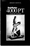
StairMaster
OWNER'S MANUAL
•
StairMaster
yam
THE WORKOUT OF
•
UFE
StairMasler, Inc. • 6015 North Xanlhus Avenue. Tulsa, Oklahoma 74130 • (918) 425-5588 • (800) 331-3578
Table of Contents
•
,
CONGRATUlATIONS...
3
SPECIFICAnONS
3
INsT'AUATION
3
PROPER CUMBING TECHNIQUES
3
INTRODUCTION
4
WARNINGS
5
BENEFITS
6
COMPUTER BASICS
6
1. Attract Mode
6
2. Data Entry
7
3. Exercise
7
4. Exercise Summary and Goal Complete
7
OPERATION
7
1. Scrolling Message
8
2. Character Table
8
3. Changing The Workout Time
9
4. Custom Programs
9
5 Jackpot Option
10
6. Display Check
11
7. Code Summary
-11
rnEORY OF OPERATION
12
MAINTENANCE
12
1. Removal of Side Panels
12
2. Bearing and Stepshaft Replacement
12
·1·
•
CONGRATULATIONS...
You have purchased the finest and most innovative exercise machine available. It is
designed to be durable and provide unequaled physical development Please read
this manual thoroughly, it provides you with
very important information on operation and
service and should be required reading for
anyone responsible for operation or maintenance of the machine. Thank you for
choosing the Gauntlet, you will find it to be
a most popular and beneficial addition.
SPECIFICATIONS
posed to perspiration. Custom length DC
cables, brackets for multiple power supplies,
and other optionS are available :from StairMaster.
INSTALLATION
The Gauntlet unit comes fully assembled,
pre-lubricated and ready for use.
DOOR WIDTIiS: The Gauntlet is designed
to pass through a minimum width door of
32". H a door is somewhat less 'than 32", it
may be necessary to remove the handrails to
provide adequate clearance. Tb..is is a difficult procedure and should not ~c done unless absolutely necessary. (If necessary, first
consult a factory service representative).
All specifications are for a fully assembled
Gauntlet.
CEIUNG HEIGHT: 8 1/2' to 9' is needed
for proper use of the Gauntlet.
Physical:
Temporary wheels are already
installed in the center of gravit) position.
Balance the unit on the wheels and move
slowly to the desired location. Toe wheels
must now be removed. To do so, tilt the
unit forward until the wheels are slightly. off
the floor, remove the pin located just right
of center axle by grasping and pulling outward. Grasp each wheel and collapse axle
inward, remove wheel assembly from both
right and left sides of support legs. Store
wheel assembly for future use.
Length
Width
Height.
Weight
WHEELS:
51.0 inches
32.0 inches
79.5 inches
391 pounds
Electrical:
Voltage
CUrrent
Power Consumption
Frequency
l10 VAC
O.5 aIIlpS
.55watts
50/60 Hz
LEVEUNG: Only the rear casters are adjustable. Adjust both casters in as far as possible, then back out as necessary to obtain a
level position.
The wall plug-in power· supply provides 12
VDC at 2.5 amps to power the console. The
low voltage eliminates the danger of electriCal shock as long as the. power supply is located away from the machine and not ex-
·3·
•
. PROPER CLIMBING
TECHNIQUES
This chapter precedes the introduction because development of a satisfactory climbing
technique is of absolute importance.
• Never pull or push on the bandrails.
Pulling on the handrails will increase the
work being done by the user resulting in a
calorie count lower than the actual work
that was performed and can cause premature wear of machine components. On
the other hand pushing on the handrails
will cause the calorie count to indicate
higher than actual. Caution,' beginning
users may have a tendency to support
their weight on the handrails instead of
keeping up with the machine. The handrails are intended to stabilize users, not to
support them.
• While climbing on the machine, stand'
straight and relax as much as possible.
• Climb fast enough to stay in the middle
of the staircase.
INTRODUCTION
The StairMaster Gauntlet is a vertical climbing machine providing an aerobic workout
equivalent to climbing stairs, without the inertia loads arid skeletal trauma which may be
associated with some aerobic activities including conventional stair climbing. The
machine is computer controlled to offer
automated timed workouts from five
minutes to forty-five minutes as selected by
the owner. There are eight preprogrammed
workouts available with ten levels each. 1n
addition there is a manual workout so the
user may pace himself or experiment with
the various speeds. There are also ten user
programmable workouts which are addressed with the special featur~.
All
programs feature computer controlled
speeds from 4 METs to 17 M:Ers (approximately 26 steps/minute
to 138
step~minute).
The computer displays
calories burned, average MET J1L te, floors
climbed, and equivalent miles at the conclusion of the exercise. The user should
familiarize himself with the warnin~, and at
least the functions of the computer overlay
and display area before attempting an exercise. It is also recommended that. the first
time user start with a manual ocercise to
develop a climbing technique (see section on
Proper Climbing Technique) 8D~ become
familiar with the electronics. MDJy special
features are included in the Gaunt! <t such as
the exciting Roller Coaster Progr2lIl, three
color display, Run/Stop safety S'tVitch conveniently located on right handrail,molded
step tread is replaceable without gluing, inverted hinges on steps for better appearance
and reduced corrosion, and alteraator load
eliminates brake adjustments. The following
is an explanation of terms used tlJroughout
this manual.
CALORIES... The calorie summary at the
end of the exercise displays the toual number
of calories burned. Accurate calode calculations are difficult because of suc~ variables
as post exercise metabolic influence etc. In
our attempt to be as precise as pOSSIble with
this calculation, you may find the Gauntlet
calorie calculation to be conservCLtive wben
compared to the occasional e¥Jggerated
calorie calculations of other equipCllCnt
• MET... 1 MET equals tbe a "Dount of
oxygen you consume at rest. The displayed MET is the multiple of tie resting
MET. Etample... If you are ex ercising at
8 METs, you are using eight times the
amount of oxygen you would at rest. To
§
•
be precise, o~e MET equals 3.5 milliliters
of oxygen per kilogram {)f body weight
per minute.
parent heart rate or any othel external influence shoul4 never over ride one's own
judgement when exercising on the Gauntlet
• AVERAGE MET... -The value obtained
by averagmg the MET rates of all 30 exercise intervals including the warm up
and cool down.
Do not use, adjust, or operate StairMaster
exercise equipment without proper instruction by owner authorized personnel.
• FLOORS... Since step height on the
Gauntlet is variable, the calculation of
floors is based on total work performed
and expressed as one floor equaling the
amount of work required to climb 16
eight inch steps or 10.2 feet.
• MILES... 1 mile is equivalent to 48 floors
climbed. This calculation is based on
standard work equivalents.
All Gauntlet calculations are directly
equivalent to other StairMaster products.
WARNINGS' .
.
.
Anyone not accustomed to serious exercise
should always consult a doctor before using
any exercise device including Gauntlet
Definitely do not allow anyone with a history
of heart trouble or high blood pressure to
use Gauntlet except by doctor's prescription
or consent.
Be cautious of overweight people using
Gauntlet for the first time even though they
may have no history of physical difficulty,
they may assume it to be far less difficult
than it is, resulting in over exertion.
When using Gauntlet for the first time one
should remain in the lower speeds until confident before trying the faster speed selections.
Persons wearing eyeglasses may have more
difficulty getting used to the machine and
should be given extra attention until familiar
with the Gauntlet.
Do not allow small children .to play unattended near the Gauntlet, especially near
the moving staircase. Serious injury could
result from an infant or small child's fascination with the mQving components of the exercise machine.
Never exercise alone if infants or small
children are around, it is difficult to observe
children's actions from the exercise position.
Keep hands and feet away from moving
parts while machine is in use. Never attempt to repair or adjust machine while in
use.
Do not operate equipment \With loose or
damaged parts. Notify owner or authorized
personnel of any problems with equipment.
Although the equipment manufactured by
our company has been thoroughly inspected
prior to shipment, proper installation and
regular maintenance are required for safety.
Maintenance of the exercise equipment is
the responsibility of the equipment owner
and not of StairMaster or its distributors.
StairMaster recommends before initiating
any exercise program, that the user obtain a
complete physical examination from a medical doctor, and enlist the aid of the doctor in
develot>4J8 an exercise program suitable for
user's current health status.
Speed and duration of exercise should always be subject to how a person feels, ap-
-5-
•
Failure to comply with these instructions
may result in personal injury.
BENEFITS
1. MET and other data electronically computed by precise formulas based on the classic work formula of weight and distance. No
other ergometric device 50 accurately
employs this physical equation for the purpose of expressing work and associated
physiological projections. (All formulas confirmed accurate by several independent
studies).
.'
2. When desired, the Gauntlet can produce
the quickest rise in heart .rate and vo/2 of
any device, yet its wide range of speeds can
accommodate the infirm or poorly conditioned with equal ease.
3. MET .levels are directly proponional to
speed since work output is weight dependent, MET levels remain the ,same for anyone
regardless of body weight at a given speed.
On Gauntlet, MET -levels range from 4-17
METs. This feature allows direct comparison, when desired, between individuals
of similar demographics but with different
weights, when tested under identical speed
conditions, such as athletic teams, military
recruits, etc.
4. The Gauntlet never needs calibration
since the resistance is body weight, not frictional devices which will wear out. Speed is
computer 'checked 100's of times per second,
so calculations are constantly updated and
always aCcurate.
••
S. Due to the large muscle mass used when
exercising on the Gauntlet, it is possible for
subjects to reach met levels impossible or
impractical to achieve on other equipment.
6. There' are DO inertia or shcxk loads to
stress joints, ligaments or muscles as is the
case with other popular forms
exercise.
0"
7. There are DO weight limits (lD pauntlet.
It bas been operationally tested at weight
loads exceeding sao Ibs.
8. No RF interference is generated by the
mechanics of the Gauntlet beca.lISe there are
no electrical motors. The stair case is
powered by body weight and sped controlled by an electromechanical bnuing system.
COMPUTER BASICS
The purpose of the computer console is to
provide automation of the workout and a
"friendly" method for obtain i ng necessary
data and displaying workout results. Before
your initial exercise on the GallDtlet, it is a
good idea to become familiar Vt'ith the computer console and its operation There are
three areas of the console whiell provide the
user interface to the system; the keypad
which allows data entry and p7()gram selection, the display area which pnvides information to the user either by charting
workout progress or providing written questions and statements, and lastly the interval
timer which displays time ren...uining in the
current exercise interval.
The computer console bas four operational
modes:
1. Attract Mode
This is the machine's idle time and is characterized by either the simulated EKG or a
scrolling message in the displa::y area. Pressing the reset button from an:)' other mode
will return the computer to the attract mode
as will allowing the timer to time-out in a
rest or when answering a question.
"dots, the bottom dot represents a 4 MET
speed and all the dots of a column represent
a 17 MET speed. The MET' equivalent for
This is the phase of the program where the
each row of dots is shown on the left hand
user must ~put information the computer
needs to control speed and accurately calcu- " side of the display area. The exercise will
allow a" single rest period of two minutes. If
late statistics. This mode is entered only
the rest period expires or a second rest is atfrom the attract mode by pressing reset or by
tempted the computer will revert to the atstepping on one of the steps. The first questract
mode and the summary data will be
tion asked is "ENTER WEIGJIT'. To
lost. The staircase may be slowed to a near
respond simply press the appropriate numstop at any time by pressing the RunlStop
bers on the keypad followed by [ENTER].
button on the right handrail.
The range for weight is 1 to 999 pounds.
This is used to calculate the calories burned
during the exercise. The next question is
4. exercise Summary and Goal
·SELECf PROGRAM". There are nine exComplete
ercise programs to chose from in the top
three rows of the keypad. The outlines on
The exercise summary is automatically disthe keys correspond to the relative speed
played after the last interval is completed.
levels of the particular program. H manual
The summary will display calories burned,
is seleeted,the computer has completed the
average MET rate, floors climbed and
data entry, if not. then it will prompt with
equivalent miles. Each new display is ac"ENTER LEVEL" and wait for an entry becompanied by a ringing sound to alert the
tween 1 and 10 with 1 being the easiest
user to the new display. Following the sumworkout.
mary is a goal complete message or the jack-
2. Data Entry
•
3. exercise
•
The exercise portion of the program will always follow the data entry. The exercise will
start with a prompt which rotates through
"START EXERCISE", length of workout.
and an outline of the workout unless its
"Roller Coaster" or ""manual". "Once the
steps start moving the prompt disappears
and the workout is displayed. The program
will be held at this point until the :Run/Stop
button is pressed. The workout is divided
into 30 intervals, each one lasting 30 seconds
(assuming a 15 minute workout, otherwise
they will represent 1l3Oth of the actual
workout). The flashing column is the current interval and the interval timer shows
time remaining in that interval. The speed is
represented by the height of the column of
·7·
pot display depending on the owner selected
option. The computer will return to the attract mode after completing the summary
and goal complete.
OPERATION
Before operating the machine, verify power
is available to the machine by observing
either the simulated EKG or scrolling message in the display area Be sure to read the
earlier section on proper climbing technique
and remember the basics. Relax, stand up
straight and keep up with the machine.
The staircase will continue moving slowly
until programing is completed and the .
Run/Stop Button on the right handrail is
pressed.
E
1
P
s:
o
e
p
1=
f
s
t
E
I
.t
!
c
]
•
J
•
To initiate a program, stan by stepping up
onto the steps. They will start to fall slowly
under your weight.. Spend a few ·seconds
here getting used to the feel of the machiile
and get used to not pushing or pulling on the
handrails.
Observe the display area with the message
-ENTER WEIGlIT' with an arrow pointing
to the numeric keypad. Enter your weight on
the keypad and press the enter key when it is
correct. Entry errors may be erased by pressing the clear key.
The display area should now be prompting
with "SELECT PROGRAM" and an arrow
pointing towards the top three rows of the
keypad. To familiarize yourself with the
machine, selected the manual program.
Upon pressing the Run/Stop button, the
steps move faster than before and you are
now exercising at four METs. AS you become comfortable on the machine try USing
the up and down arrows to adjust your speed
(manual is the only program which allows
speed changes :with .the arrow keys). The
column flashing shows which interval is active and everything to the left of it shows a
history of the completed intervals. If a
preprogrammed workout had been selected,
all intervals would be shown and the
columns to the right of the flashing one
would show the user what to expect. Continue through the entire workout and
develop a feel for your abilities on the
machine. After the last interval is complete,
the console will produce a ringing sound and
display calories burned for several seconds.
This is followed by average MET rate, floors
climbed, and miles ran, each accompanied
by the same sound and displayed for the
same length of time. Remember your
average MET rate to use as a guide when
selecting a level for one of the
preprogrammed workouts (subtract fOUT
-8.
from your average MET level aDd use this as
a level for one of the preprogrammed
workouts. This is intended to give you a
starting point As you become experienced
on the machine, adjust the level to-suit your
abilities).
.1. Scrolling Message
When this option is in effect, the simulated
EKG is replaced by a scrolling message
which the owner has entered This message
may announce club specials, birthday greetings, prizes. etc. The option is automatically
asserted when a message is entered but then
can be disabled without loosing the message.
There is also an optional teletype sound effect which may accompany the message.
Construct your message first on paper using
the codes for letters, numbers, and symbols
shown in the following chart. All codes are
two digits. The computer will automatically
accept and display the character after the
second digit is pressed. H you make a mistake, pressing [CLEAR] will remove the last
digit pressed or remove the characters from
the display in reverse order if you continue
to press [CLEAR]. It is not necessary to
leave a space at the beginning or end of your
message as the computer does this automatically. The message may contain up to 128
characters including spaces.
2. Character Table
A=50 E=54 1=58 M=62 Q=66 U=70
8=51 F=55 J=59 N=63 R=67 V=71
I
I
I
I
I
I
C=52 G=56 K=60 0=64 5=68 W=72
D=53 8=57 L=61 P=65 T=69 X=73
I
•
Y=74
7=07
+=22
'=27
Z=75° 3 =03
8=08
$=23
-=28
_=76
4=04
9=09
.=24
-=29
0-=00
5=05
1=20
%=25
#=30
1=01
6=06
-=21
1=26
.=31
:=32
2=02
To program the message:
• Computer must be in the attract mode.
• Press 7607 followed by [ENTER]
• Note message appearing on display as it is
entered.
• When message is complete, press
•
[ENTER]
• Your message will now begin scrolling
and the machine ohas returned to the attract mode.
Sample Message...EXERCISE CAN BE
FUN,54,73,54,67,52,58,68
,54,76,52,50,63,76,5 1,54,76,55,70,63
[ENTER]
The following codes allow optional control
of the scrolling message.
• press 2123 [ENTER] • This turns message off but retains the message in the
computers memory. The simulated EKG
will be displayed.
• press 2121 [ENTER] - This turns the
message back on if there is one in
memqry.
•
sound off.
0
• press 40 [ENTER] - turns the teletype
sound on.
• press 41 [ENTER] • turns the teletype
-
-
-
--
Just as with the EKG display, pressing
[RESET] or moving a step will put the
machine into the data entry mode.
3. Changing the Workout nme
The standard workout time is 15 minutes for
all programs excluding custom programs.
This time is the sum of all 30 interval times
shown by the workout display. Each column
in a standard 15 minute workout represents
a 30 second interval. Each interval time is
adjusted to lI30th of the total time if a new
time is selected. The workout length may be
adjusted by use of this option to any number
of minutes between 5 and 45. The new time
remains in effect for all standard programs
until it is modified again. We recommend
that this code not be public knowledge and
that programs remain at 15 minutes unless
otherwise needed.
To change the time:
• The computer must be in tbe attract
mode.
• Press 1010 [ENTER]
• Enter the desired time (one or two
digits), press [ENTER]
The program will return to the attract mode
and the interval timer will reflect the proper
time to achieve the new workout time. This
time setting feature does not affect the
length of any custom programs selected.
4. Custom Programs
Custom programs are user designed
workouts retained in the computers
memory. After entering the code to access
custom programs, the computer will prompt
----------------------
for a program number 1 to 10 (there are ten
custom progr~).
A workout time is
programmed along with the 30 MET levels.
There are two parts to this section, one on
inputting the programs and one section on
using the program. We suggest that the
users mow the codes to access the programs
but not the codes to modify them to prevent
lampe/ring.
To program a workout:
• Computer must be in the attract mode.
• Press 1650 [ENTER]
• "ENTER PROGRAM" will appear on
the display.
• Enter the number of the program you
wish to modify, press [ENTER] .
. If the program number entered has not
been programmed, you will see a solid
row of dots representing 4 METs for all
intervals, otherwise the previous program
will appear and can either be modified or
completely written over.
.
• The flashing dot or column is the one you
can now modify. Use speed arrows to
move column up or down, use [ENTER]
to move cursor to the right and [CLEAR]
to move cursor to the left.
• When all the columns are correctly
programmed, press [RESET] to save "the
program.
• "ENTER TIME" will appear on the display.
•
• Enter the desired time between 1 and 45
minutes. It should be noted that unlike
standard programs, custom programs
allow the time to go down to one minute.
• Press [ENTER J
Your program has now been savec:i and the
machine will return to the attract IDode.
Using custom programs:
• Press 4101 [ENTER]
• Enter the desired program nuz:nber from
1 to 10 and press [ENTE}~J
• Continue as with a standarcl exercise
program.
Note: You may only select a n~ber that
has been previously programmed Otherwise
the computer will ask you to r-eselect the
program number.
5. Jackpot Option
At the end of the "exercise s..rrnmary (at
workout completion), there is fa goal complete message.
This messase may be
replaced by a Las Vegas style s]ot machine.
When the wheels of the slots stop turning,
the window will spell out either 'THE END"
or "YOU WIN". The odds of "jnning may
be programmed anywhere between 1 in 5 to
I in 9,999. The computer will then randomly
select a winner and display -YOU WIN" instead of the usual 'TIlE END -, After displaying "YOU WIN", the comp"1lter will wait
for the reset button to be pres.sed and then
display the current odds. 'Il13s allows the
owner to confirm there bas "been no tampering. The odds are modified by the computer
to allow a lengthy workout to bve the same
win potential as several short \1lWOrkouts. The
entered od4s are based on th. e standard 15
minute workout.
The jackpot option remains in effect until
disabled by entering zero odds. H there is
only one prize, remember to disable the op-
tion when there is a winner. StairMaster and
it's distributors assume·no liability stemming
from the use of the jackpot option. Use of
this option may be governed by laws or ordinances in your ar~a.
To turn the jackpot option on, program odds
of 5 or more. To tum off the option and
return to the standard goal completion message at ·the end of the .summary, program
odds to zero.
• Computer must be in the attract mode.
• Press 8089 [ENTER]
"ENTER ODDS" will appear on the
screen.
• Enter odds between 5 and 9,999 or enter
zero to disable the option. Press
[ENTER]
•
The display check is intended as a factory
test, but it gives the owner the opportunity
to test the display if there is S<lme doubt as
to whether all the dots are working.
To perform a display check:
• The computer must be iD the attract
mode
• Press the up speed arrow followed by 15
[ENTER]
Enter Odds:
~
6. Display Check
• The display will say "DISPLAY CHECK"
for a few seconds, and then turn on all of
the yellow dots. The other colors may be
tested as follows:
1. Red dots
2. Green dots
3. Yellow dots
• The compute! automatically returns to
the attract mode.
When the computer has a winner, the "YOU
WIN" display will remain active until
[RESET] is pressed. The odds will display
after [RESET] until it is pressed a second
time. This is to give the owner a chance to
verify ·the win.
Other jackpot codes:
• Press 3121 [ENTER], to display the current odds. [RESEll will return the computer to the attract mode.
• Press 8089 [ENTER], 0 [ENTER] to disable the jackpot option.
O. No dots
• Press [RESE1] to terminate the display
check.
7. Code Summary
• Scrolling Message Codes:
Program message
Message on
_
Message off.
Teletype sound 00.
Teletype sound off
_" 7607
_..2121
- 2123
__
40
__ 41
• Workout Time Code:
•
Change workout time.......- _ ........1010
·11·
tilt
• Custom Workout Codes:
Programming custom workouts .l650
Using custom workouts
4101
• Jackpot Codes:
Set odds or disable option........•...8089
Display current odds
.3121
• Display Check:
Start test..
•
UP ARROW-15
MAINTENANCE
VOLUME CONTROL
1. Removal Of Side Panels
The volume is set at the factory but may be
adjusted by the owner. To set the volume,
use a sma]] flat blade screw driver to adjust
the volume control through the hole in the
bottom of the console. Clockwise rotation
increases the volume (facing the bottom of
the console).
THEORY OF OPERATION
•
a continuous rotary motion. This rotary motion is directed to a gearbox which in tum
drives an alternator at sufficient RPM to
provide a smooth, reliable means pf speed
control. Excess electrical energy created
during this process is dissipated in an external electrical resistor in the form of heat. In
summary, the work being performed by the
user (kinetic energy) is converted to electrical energy, which is then converted and dissipated as heat. The size of the electrical
load is controlled on the field side of the alternator. This manages the energy at low
current and limits the heat producing components to the load resistor which is
designed to dissipate heat well in excess of
the Gauntlet's requirements.
The Gauntlet is not motor driven. The
electrical supply to the unit is necessary .only
for reliable and consistent operation of the
electronic console. This feature also allows
the electronics to be viewed when the
machine is not being used as opposed to
some other equipment which must be in use
to provide an active and viewable display.
The body weight of the user provides kinetic
energy used for speed control and resistance.
This is accomplished by a drive system which
sums the oscillating motion of the steps into
·12·
1. Side panels are attacbed magnetically and
are kept in proper alignment by two screws
located at the top extreme ends of each side
paneL To remove pane~ remove screw and
lift panel at any convenient point until mag.
netic contact is broken, hold panel securely
and pull outward.
2. To re-install, align boles in top ends of
panel with alignment holes before allowing
panel to make magnetic conta~t. Once
panel is placed over holes, press panel into
place until magnetic contact is re-established
around the entire perimeter of the panel and
re-install screws.
2. Bearing and Stepshaft
Replacement
1. Follow side panel removal procedure and
remove side panels.
•
2. Rotate steps until the desired step is 10-'
cated midway between top and bottom axles
underneath machine.
3. It will be necessary to have a person the
opposite side of the machine to hold the nut
on the other end of the stepshaft while unscrewing nut.
4. Remove master links and cbain.
6. Drive Chain Removal
1. Remove master link.
2. lift idler arm and remove chain. .
4. Unscrew nut, remove bearing and washer.
7. Sprocket Removal
5. Using rubber mallet, tap stepshaft through
chain until enough length is exposed on the
opposite side to pull the stepsbaft completely free from step.
1. Follow procedure for removing steps and
chains and remove both.
6. Note: Washers located between the step
and chain on either side will fall free when
stepshaft is removed. Be sure to retain the
washer to re-insert when stepshaft is re-assembled.
2. Loosen shaft set screws in pillow block.
3. Remove pillow block nuts.
4. Sprocket assembly 'can then be removed.
5. Remove pillow block bearings from
sprocket assembly.
7. Remove remaining bearing and washer.
8. Speed Reducer Removal
8. To re-assemble follow reverse procedure.
1. Loosen Alternator. Alternator Bracket
and bolts put slack in Alternator-Reducer
belt, lift belt off transmission hub,
4. Step Removal
1. Follow bearing and stepshaft replacement
procedure to remove stepsbafts.
2. Follow procedure for Drive Chain
Removal and remove drive chain.
2. Remove one step at a time, rotating steps
in a clockwise rotation as viewed from the
left side of machine.
3. Remove transmission brace.
4. Remove bolts.
3. Repeat above procedure until all steps
are removed.
5. Pull Speed Reducer towards you.
6. Remove idler arm and Belt Hub.
5. Chain Removal
7. Remove Roll Pin in sprocket hub and
shaft to remove sprocket hub.
1. Follow procedure for removing steps, and
remove all steps.
•
8. Remove spring.
2. Loosen screws on bottom axle.
3. Loosen nuts. This will allow chains on
either side to loosen.
-13-
•
6. Leave lower sprocket assembly loose at
this time.
9. Speed Reducer ·Installatlon
1.
Install sprocket assembly onto Speed
Reducer shaft. Note orientation. Tighten
set saew on key.
2. Install idler arm, spring, and belt bub to
the reducer, put roll pins thru sprocket hub
and shaft.
3. Install Speed Reducer assembly on main
frame using washers and bolts.
bolts.
Tighten
Assemble transmission brace to mam
frame and Speed Reducer.
4.
S. Put Belt on Transmissiop. Tighten Alternator-Reducer Belt. Bolt to Alternator and
Alternator Bracket.
8. It is important at this time to insure that
the boles for the stepshaft in the chain assemblies are directly in line with each other.
To do this, pass a stepshaft thru the holes in
the links of one chain to the holes in the
links of the chain of the opposite side.
Rotate the sprocket assembly until the shaft
comes in contact with the sprocket teeth. If
the chains are in alignment, the shaft will
contact the sprocket teeth at exactly the
same moment. If the chains are not in alignment, relocate the chain in the sprocket
teeth until alignment occurs.
9. Assemble master link in chain assembly
on opposite side.
10. Sprocket and Chain
A~sembly Installation
1. Assemble pillow block bearings to axles.
Note: Set screws go to the outside. Do not
tighten at this time.
2. Assemble bearing adjusters and sprocket
assemblies to main frame studs. Do not
tighten at this time. Upper sprocket assembly small sprocket goes to the left side of
machine.
3. Tighten bearing adjuster set screws on
top sprocket assembly until pillow block
bearings are in the top most position. Then,
back out set screw two turns on each bearing
adjuster.
•
Assemble chain assemblies to sprocket
assemblies. Connect chain on one.side with
master link.
7.
4. Using scale, center sprocket assembly between the main frame side rails.
5. Tighten nuts on both upper sprocket assembly pillow block bearings.
10. Tighten bearing adjuster screws on bottom sprocket assembly until chains on either
side are of equal tension. Note: Tighten
until chain slack is removed. Do not tighten
past this point.
11. Using scale, center bottom sprocket assembly between sid~ rails, Tighten nuts on
bottom pillow block bearings.
12. Tighten all set screws in pillow block
bearings.
11. Stepshaft and Bearing
Assembly
1. Note: Two people are required for the
following procedure.
2. Working from underside of machine,
position a step in place and pass a step shaft
thru the links of one chain assembly, thru
.14..
•
the hinge of the front pan of step, and on
thru the links of the chain on the opposite
side. This should suspend the step in place.
3. Tighten these screws an equal amount on
both sides until the correct chain tension is
achieved.
3. Position second step in place..
4. Re-tighten bearings DUts.
4. Insert step shaft thru the chain link. In-
5. To loosen chain follow the above procedure, except loosen set screws 8Il' equal
amount on both sides until the required tension release is obtained.
stall washer.
5. Connect the two step hinges together and
push the shaft thru the step hinges.
6. When shaft emerges from step hinges on
opposite side, install washer before pushing
thru the chain links on the opposite chain.
7. Install washers and bearings on both ends
of shaft:
8. Assemble nuts on either end of shaft and
.tighten. Note: Deformity of threads of one
end of nut. This goes to the outside.
•
9. Tighten nuts until approximately one and
one half threads are visible from end of
shaft.
10. Repeat procedure until all steps are in
place.
11. When all steps are in place there should
be approximately 1 1/2 inch chain. deflection.
12. Step Chain Adjustment
1. To tighten chain, loosen the two bearing
retainer nuts on each of the two pillow block
bearings located on either side of the unit.
Just loosen slightly, do not remove these
nuts.
•
2. Observe the adjustment set screw which
seats against each of these bearings. A 3/16
inch Allen wrench is required to unscrew the
screws.
13. Alternator Belt AdJustment/
Replacement
14. Machine Alignment
1. It is important for the longevity of the
component parts of the machine that it be
aligned properly.
2. To visually check the aligmnent of the
machine, stand in front of the machine and
obseRve The Steps And Chain As They
Rotate Around The Lower Sprocket.
3. Note the shaft on either side of the
machine as it initially engages the sprocket
teeth. If the machine is misaligned, you will
note that on one side, the step and the chain
tend to separate when the shaft engages the
tooth. On the other side the step and the
chain will tend to come together.
4. To align the machine, loosen the set
screws in the bottom pillow blocks. H the
chain and the step tend to separate on the
left side of the machine, move the sprocket
assembly shaft slightly to the right. If the
chain and the step tend to separate on the
right side, move the sprocket assembly to the
left.
5. Movement of sprocket assembly can be
accomplished by tapping the end of the
sprocket assembly shaft at the pillow block
bearing.
·15·
------~---------------
-
•
6. Note: It· may be necessary to move both
the top and bottom sprocket assembly to
achieve alignment. Follow the same procedure as above to move upper sprocket assembly.
7. Re-tighten set screws.
8. When the machine is properly aligned
you will. see a very small or no amount of
separation between steps and chain as the
steps rotate around the bottom sprocket assembly.
LUBRICATION
1. STEPSHAFTS AND HINGES WITH
WD40, 1-3 TIMES PER WEEK
e·
2. CHAINS wrrn SAE 30 wr.MOTOR
OIL, 11lME UGHrLY PER ·MON1E
NOTE: 1. Lubrication frequency will vary
with the amount of use.
2. People using the Gauntlet tend to
perspire heavily. Perspiration will rust metal
rapidly. Therefore, it is important that the
lubrication and periodic cleaning requirements of the machine be observed.
3. The stepshafts are most effectively lubricated from a position in front of the unit.
Rotate each step into position and attach the
red tube to the nozzle of your WD-40 to
direct the lubrication only on the hinge area.
NOTE: Do not spray lubricant onto the rubber step, as this will create a potentially
dangerous condition.
e
4. The inner binge should be lubricated with
WD-40 by removing the magnetic side
shields and spraying -each step individually
from inside the unit. The steps can be
moved from the outside by pushing the step
in the opposite direction (clockwise) of it
normal function.
CLEANING PROCEDURE
1. Clean the machine as often IS usage dictates. This may be done with U1f acceptable
cleaner and soft cloth. Be especially attentive to cleaning the step hinges as perspiration tend to accumulate here, leading to
eventual cosmetic corrosion.
TROUBLESHOOTING
Electrical problems are limited to four areas; the console, the power supply. the cabling.
and.the alternator. The purpose of this section is to help identify problems-. We do not
recommend user servicing of the console. Consult panel removal in Mainten arlee section
for procedures dealing with the load resistors or the altemator.
1. Electronic
Symptom:
Probable Causes:
No display or sound on power up.
EleetricaJ power not ava....ilable at wall
outlet. Plug a known goc=»d device into
the outlet (i.e. a lamp, r~d.io etc.). If
outlet is not active, use -=t good outlet
or call an electrician. .
Power supply may be bac::l Use a volt
meter to verify power a t coaxial plug
on the power supply cesble. Voltage
should read between 12 and 15 volts.
If supply is bad, order L. replacement
from StairMaster.
•
To verify the cable h.=as not been
damaged, disconnect the gray cable at
console and measure voL ~ge between
pins 5 and 4 of the cC=»JlDeetor (the
pins are labeled on the:: face of the
connector). It should aIsc::::J indicate between 12 and 15 volts.
The only part left is ta e electronics
console. If possible, ~p consoles
from another machine -to verify the
problem.
•
-17-
•
Console display has several dots lit
but doesn't function.
MomentariIy unplug the :machine.
Upon plugging back. in, if the console
operates properly, the symptom was
caused by 8 problem with the 110
VAC power from the electric company. If this occurs frequently, it
would be 8 good idea to try the
machine on a different electrical circuit.
If the above does Dot resolve the
symptom, the electronics console is
most likely the problem. If possible.
swap consoles from another machine
to verify the problem.
•
Machine wi)) not speed control.· The
speed keeps increasing beyond speed
shown.
The load resistor may have malfunctioned. Check for continuity between
the + BAT terminal of the alternator
and ground. The resistance will read
zero ohms on most meters (0.5 ohms
actual resistance).
The console may also cause this
problem. Swap consoles if possible. _
The conductor in the gray cable may
Dot be continuous. Use an ohm meter
-to check for continuity from the field
terminal of the alternator to pin. 2 of
the connector (pin nunbers are
shown on the face of the connector).
Machine will not speed control. Runs
slow all the time.
•
The electronic console has failed,
swap consoles if possible.
•
The conductor in the gray cable may
not be continuous. Use. an· ohm
meter to check for continuity from the
stator terminal of the alternator to pin
3 of the connector (pin numbers are
shown on the face of the connector).
The console operates properly up to
the start exercise display. but will not
continue into the exercise:
The Run/Stop button may have failed.
The self test feature in the console
will identify this problem. In the attract mode press 101 [ENTER], the
console will respond by displaying
"ENTER PROGRAM". Press 3 to
start the switch test. The bottom row
of lights will indicate the status of
each switch on the keypad and the
Run/Stop button. The far right LED
should go out if the button is pressed.
H it doesn't go out, check to be sure
the cable is securely plugged into the
console. H the cable is plugged in,
.order a new RunlStop switch from
StairMaster Service.
•
2. Mechanical
Symptom:
Probable Cause:
Popping sound coming from chain
and sprocket area
Steps mis-aligned (See machine alignment procedure)
Steps move in a jerky or erratic motion
Speed Reducer remove and replace
(see Speed Reducer removal)
Grinding noise coming from the
machine when in operation
•
-19-
A Broken Stepshaft (See Bearing &
Stepshaft Replacement)
B. Speed Reducer remove and
replace (See Speed Reducer .iemoval)
•
C. Stepshaft Bearing off (See Bearing
& Stepshaft Replacement)
Steps will not move
A
Remove and replace Speed
Reducer (See Speed Reducer
Removal)
B. Step, Chain or Bearing obstruction
Check and remove foreign object
Squeaking sound coming from step
area
Unlubricated shaft and billge (See
lubrication procedure)
•
•
·20·
~----~
------_.~----
GAUNTLET PARTS LIST
•
•
•
•• Parts and prices are subject to change without notice
Part #
SM20675
SM22934
SM10753
SM20103
SM20859
SM21164
SM20693
SM10754
SM23082
SM10037-03
SM20012
SM22065
SM10059
SM10860
SM20547
SM10395
SM10396
SM10397
SM10398
SM10452
SM10195
SM20511
SM20513
SM20509
SM20047
SM20508
SM20022
SM20292
SM21329
SM20804
SM21147
SM22190
SM21330
SM20017
SM20157
SM25305
SM10205-03
SM22032
SM22042
SM22092
SM22036
SM22029
SM22018
SM22110
SM22063
SM20466
SM20682
SM20018
SM10887
Part Description
CS ADAPTER.HANDRAIL
CS ASSY.RELAY/RESISTOR.GAUNT.
CS POWER CONNECTOR ASSY. 12/
CS SPACER.HANDRAIL.PLASTIC
ADAPTER. POWER CORD.3 PRONG
ALT. ASSY. GAUNT/STEP.PRESTOLI
ARM.IDLER
ASSY.CABLE CONSOLE. NEW RELAY
BEARING. 608 2Z
BEARING.ADJUSTER.STEPMILL. W/B
BEARING.PILLOW BLOCK
BOLT..500-13 UNCX3.75.HEX HD
BRACE.TRANS.
BRACKET TRANSMISSION 7000PT
BRACKET.TRANS.. OUT
CABLED.C 12FT
CABLE.D.C 16FT
CABLE.D.C 20FT
CABLE.D.C 24FT
CABLED.C .. 8FT
CHAIN ASSY.#40 (NEW)
CONNECTOR. RlR. 3-PIN. MOLEX
CONNECTOR. RlR. 6-PIN. MOLEX
CONNECTOR.TUBING
COITER.HAIRPIN.PLATED
FASTNER.PUSH NUT
TAPEMAGNETIC
GROMMET.1/4 ID.1/16WALL
H.S. GEAR ASSY.BISON
HANDGRIP. MANDREL FORMED
INSTRUCTION.SHEET GAUNT.RETRO.
KNOB.CONSOLE..250-20x2.00 STUD
L.S. GEAR ASSY.BISON
LEG LEVELER
L1NK.MASTER.#40
L1NK.MASTER.#40.V2
LOWER SPRKT ASSY - 7000PT
NUT. 5/16-18 NC NYLOCK
NUT.1/2-13 NC NYLON INSERT
NUT.1/2-13 NC NYLON INSERT
NUT.1/4-20 NC NYLON INSERT
NUT.3/8-16.NYLON INSERT
NUT.5/16-18
NUT.8-32 NC HEX MACH.
NUT.LOCK.5/16-24.STEP SHAFT
PIN.ROLL.1/8 X 1-1/2 S.S.
PLATEBEARING
PLUG.BUITON
POWER CONNECTOR ASSY.
GAUNTLET PARTS LIST
•
•
•
SM20761
SM21097
SM20633
SM21096
SM21 098
SM20507
SM24379
SM20208K
SM22072
SM22028
SM22026
SM22093
SM22043
SM22081
SM22139
SM22060
SM22039
SM22126
SM22071
SM22146
SM22014
SM22015
SM22054
SM22108
SM22037
SM20184
SM20762
SM22181K
SM20114
SM20054
SM20007
SM20034
SM20001
SM20541
SM20423
SM10200
SM22109
SM22091
SM22046
SM22027
SM22031
SM22030
SM22075
SM22128
SM20528
SM20036
POWER CORD
POWER CORD. 220V. SWISS
POWER CORD. AUST.
POWER CORD. ENGLISH
POWER CORD. ITALIAN
POWER CORD.EUROPEAN
POWER SUPPLY.PS-5.2-PIN
SM STEPMILL POLV-V UPGRADE KIT
SCREW. 5/16-24 NF X 3/8 HEX
SCREW..250-20 NC X .63 HEX
SCREW..250-20 NC X 1.0 HEX HD
SCREW..312-18X.75.HEX HD
SCREW..500-13 NC X 2.0 HEX HD
SCREW.1/4-20 NC X 3 PHIL
SCREW.1/4-20 X 1/2 SELF TAP
SCREW.1 0-32X3/8.0LD STEP SHAFT
SCREW.3/8-16 NC X 1 HEX
SCREW.44 X 3/8 PHIL.
SCREW.5/16-18 NC X 1 HEX
SCREW.5/16-18 X 1-1/4 HEX
SCREW.6-32 NC X 3/8 PHIL
SCREW.6-32 NC X 5/8 PHIL.
SCREW.8 X 1/2 TYPE A SLOT HEX
SCREW.8-32 NC X 5/8 SLOT
SCREW.SET 1/4-20 NC X 3/8
SEALS. BISON TRANSMISSION (CS)
SHAFT.STEP 5/16 (OLD)
SM TOUCH UP PAINT KIT, BLACK
SPACER. ALTERNATOR
SPRING.lDLER ARM
SPROCKET.IDLER
STUD.3/8-16NC X 2-1/4
TRANSMISSION
TREAD.STEP.RUBBER
TYRAP.1/8 X 7.515
UPPER SPRKT ASSY GAUNT/STEPMIL
WASHER.#8 INT. TOOTH LOCK
WASHER.1/2 SAE FLAT
WASHER.1/2 STD. FLAT
WASHER.1/4 MED. LOCK
WASHER.1/4 X 1 00 FLAT
WASHER.3/8 USS FLAT - ZINC
WASHER.5/16 FLAT
WASHER.STEP SHAFT 5/16 FLAT
WASHER.WAVE SEASTROM
WHEEL.TRANSPORT
I