1
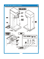
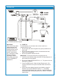
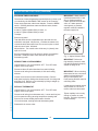
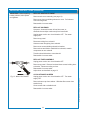
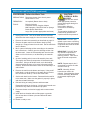
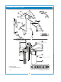
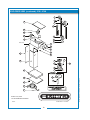
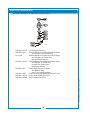
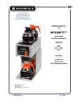
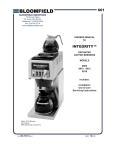
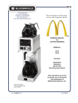
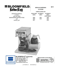
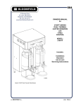
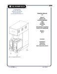
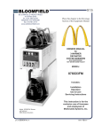
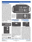
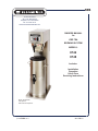
606
10 Sunnen Drive
St. Louis, MO 63143
telephone: 314-678-6336
fax: 314-781-2714
www.bloomfieldworldwide.com
OWNERS MANUAL
for
ICED TEA
BREWING SYSTEM
MODELS:
8742
8748
Includes:
Installation
Operation
Use & Care
Servicing Instructions
Model 8748 Brewer
with optional
8602 Iced Tea Dispenser
p/n 2M-76116 Rev. J
M606
100915
WARRANTY STATEMENT
All electrical equipment manufactured by BLOOMFIELD is
warranted against defects in materials and workmanship
for a period of (1 year labor, two year parts) from the date
of original installation and is for the benefit of the original
purchaser, except that:
a. airpots carry a 30 day parts warranty only.
b. dispensers; i.e., tea and coffee carry a 90 days parts
warranty only, excludes decanters.
c. decanters are not covered by this warranty
The prices charged by Bloomfield for its products are based
upon the limitations in this warranty. Seller’s obligation under
this warranty is limited to the repair of defects without charge
by a Bloomfield Authorized Service Agency or one of its
sub-agencies. This service will be provided on customer’s
premises for non-portable models. Portable models (a device
with a cord and plug ot a dispenser) must be taken or shipped
to the closest authorized service agency, transportation
charges prepaid, for services.
THE FOREGOING OBLIGATION IS EXPRESSLY GIVEN
IN LIEU OF ANY OTHER WARRANTIES, EXPRESSED
OR IMPLIED, INCLUDING ANY IMPLIED WARRANTY OF
MERCHANTABILITY OR FITNESS FOR A PARTICULAR
PURPOSE, WHICH ARE HEREBY EXCLUDED.
In addition to restrictions contained in this warranty, specific
limitations are shown below (Additional Warranty Exclusions).
Bloomfield Authorized Service Agencies are located in
principal cities.
This warranty is valid in the United States, Canada and void
elsewhere. Please consult your classified telephone directory
or your food service equipment dealer; or, for information and
other details concerning warranty, write to:
BLOOMFIELD, LLC SHALL NOT BE LIABLE FOR
INDIRECT, INCIDENTAL OR CONSEQUENTIAL DAMAGES
OR LOSSES FROM ANY CAUSE WHATSOEVER.
Service Parts Department
Bloomfield
10 Sunnen Drive, St. Louis, MO 63143
Phone: (314) 678-6336...
Fax: (314) 781-2714
www.bloomfieldworldwide.com
This warranty is void if it is determined that upon inspection
by an authorized service agency that the equipment has
been modified, misused, misapplied, improperly installed, or
damaged in transit or by fire, flood or act of God.
It also does not apply if the serial nameplate has been
removed or unauthorized service personnel perform service.
1.
2.
3.
4.
5.
6.
Resetting of safety thermostats, circuit breakers,
overload protectors, or fuse replacements.
All problems due to operation at voltages other than
specified on equipment nameplates - conversion to
correct voltage must be the customer’s responsibility.
All problems due to electrical connections not made in
accordance with electrical code requirements and
wiring diagrams supplied with the equipment.
Replacement of items subject to normal wear, to
include such items as knobs and light bulbs. Normal
maintenance functions including adjustment of
thermostats, microswitches, and replacement of fuses
and indicating lights are not covered under warranty.
All problems due to inadequate water supply, such as
fluctuating, or high or low water pressure.
All problems due to mineral/calcium deposits, or
contamination from chlorides/chlorines. De-liming is
considered a preventative maintenance function and is
not covered by warranty.
7. Full use, care and manuals may or may not be sent with
each unit, only a condensed version. Please visit our
web site to download the full version.
8. Travel mileage is limited to fifty (50) miles from an
authorized service agency or one of its sub-service
agencies.
9. All labor shall be performed during normal working hours.
Overtime premium shall be charged to the customer.
10. All genuine Bloomfield replacement parts are warranted
for ninety (90) days from date of purchase on nonwarranted equipment. Any use of non-genuine
Bloomfield parts completely voids any warranty.
11. Installation, labor and job checkouts are not considered
warranty.
12. Charges incurred by delays, waiting time or operating
restrictions that hinder the service technicians ability
to perform services are not covered by warranty.
This includes institutional and correctional facilities.
SHIPPING DAMAGE CLAIMS PROCEDURE
NOTE: For your protection, please note that equipment in
this shipment was carefully inspected and packaged by skilled
personnel before leaving the factory.
Upon acceptance of this shipment, the transportation
company assumes full responsibility for its safe delivery.
IF SHIPMENT ARRIVES DAMAGED:
1. VISIBLE LOSS OR DAMAGE: Be certain that any
visible loss or damage is noted on the freight bill
or express receipt, and that the note of loss or damage
is signed by the delivery person.
2. FILE CLAIM FOR DAMAGE IMMEDIATELY:
Regardless of the extent of the damage.
3.
CONCEALED LOSS OR DAMAGE: if damage is
unnoticed until the merchandise is unpacked, notify the
transportation company or carrier immediately, and
file “CONCEALED DAMAGE” claim with them. This
must be done within fifteen (15) days from the date
the delivery was made to you. Be sure to retain the
container for inspection.
Bloomfield cannot assume liability for damage or loss
incurred in transit. We will, however, at your request, supply
you with the necessary documents to support your claim.
xi
606 Owners Manual for 8742-8748 Tea Brewer 2M-76116
SERVICE POLICY AND PROCEDURE GUIDE
ADDITIONAL WARRANTY EXCLUSIONS
TABLE OF CONTENTS
WARRANTY STATEMENT
SPECIFICATIONS
FEATURES & OPERATING CONTROLS
PRECAUTIONS & GENERAL INFORMATION
AGENCY LISTING INFORMATION
INSTALLATION INSTRUCTIONS
OPERATION
BREWING TEA
CLEANING INSTRUCTIONS
TROUBLESHOOTING SUGGESTIONS
SERVICING INSTRUCTIONS
Deliming Instructions
EXPLODED VIEW & PARTS LIST
WIRING DIAGRAMS
xi
1
2
3
3
4
6
8
9
10
11
15
16
20
Thank You for purchasing this
Bloomfield appliance.
Proper installation, professional
operation and consistent
maintenance of this appliance will
ensure that it gives you the very
best performance and a long,
economical service life.
This manual contains the
information needed to properly
install this appliance, and to use,
care for and maintain or repair the
appliance in a manner which will
ensure its optimum performance.
SPECIFICATIONS
8742 & 8748 3 - 5 Gallon Ice Tea Brewers
MODEL
DIMENSIONS
VOLTS
WATTS
AMPS 1ø
POWER SUPPLY CORD
3 Gallon Iced Tea Brewer
8742
32-1/4” high
8742-3G
10-15/16” wide
8742-3GUK
15-11/16” deep
120
1500
12.5
220-240V
1800
7.8
NEMA 5-15P
CEE 7/VII
CW 3100
5 Gallon Iced Tea Brewer
8748
35-1/4” high
8748-5G
10-15/16” wide
8748-5GUK
15-11/16” deep
120
1500
12.5
220-240V
1800
7.8
606 Owners Manual for 8742-8748 Tea Brewer 2M-76116
APPLICABILITY
This manual applies to the following Bloomfield products:
8742
8748
1
NEMA 5-15P
CEE 7/VII
CW 3100
IL1673
2
606 Owners Manual for 8742-8748 Tea Brewer 2M-76116
FEATURES AND OPERATING CONTROLS
PRECAUTIONS AND GENERAL INFORMATION
WARNING: ELECTRIC SHOCK HAZARD
All servicing requiring access to non-insulated components must be performed by qualified
service personnel. Do not open any access panels which require the use of tools.
Failure to heed this warning can result in electrical shock.
WARNING: INJURY HAZARD
All installation procedures must be performed by qualified personnel with full knowledge of all
applicable electrical and plumbing codes. Failure could result in property damage and
personal injury.
WARNING: ELECTRIC SHOCK HAZARD
Brewer must be properly grounded to prevent possible shock hazard. DO NOT assume a
plumbing line will provide such a ground. Electrical shock will cause death or serious Injury.
WARNING: BURN HAZARD
This appliance dispenses very hot liquid. Serious bodily injury from scalding can occur from
contact with dispensed liquids.
This appliance is intended for commercial use only.
CAUTION:
This appliance is intended for use to brew beverage products for
human consumption. No other use is recommended or
authorized by the manufacturer or its agents.
EQUIPMENT DAMAGE
This appliance is intended for use in commercial establishments,
where all operators are familiar with the appliance use,
limitations and associated hazards. Operating instructions and
warnings must be read and understood by all operators and
users.
Except as noted, this piece of equipment is made in the USA
and has American sizes on hardware. All metric conversions are
approximate and can vary in size.
The following trouble shooting, component views and parts lists
are included for general reference, and are intended for use by
qualified service personnel.
DO NOT plug in or energize this
appliance until all Installation
Instructions are read and followed.
Damage to the Brewer will occur if
these instructions are not followed.
CAUTION:
BURN HAZARD
Exposed surfaces of the
appliance, brew chamber and
dispenser may be HOT to the
touch, and can cause serious
burns.
606 Owners Manual for 8742-8748 Tea Brewer 2M-76116
This manual should be considered a permanent part of this
appliance. The manual must remain with the appliance if it is
sold or moved to another location.
AGENCY LISTING INFORMATION
This brewer is
listed under UL file E9253.
This brewer meets
Standard 4 only when installed,
operated and maintained in accordance with the enclosed
instructions.
E9253
STD 4
3
INSTALLATION
READ THIS CAREFULLY BEFORE STARTING THE INSTALLATION
CAUTION:
EQUIPMENT DAMAGE
DO NOT plug in or energize this
appliance until all Installation
Instructions are read and
followed. Damage to the
Brewer will occur if these
instructions are not followed.
CAUTION:
UNSTABLE
EQUIPMENT HAZARD
It is very important for safety
and for proper operation that the
brewer is level and stable when
standing in its final operating
position. Provided adjustable,
non-skid legs must be installed
at each corner of the unit.
Failure to do so will result in
movement of the brewer which
can cause personal Injury and/
or damage to brewer.
NOTE: Water supply inlet line
must meet certain minimum
criteria to insure successful
operation of the brewer.
Bloomfield recommends 1/4”
copper tubing for installation of
less than 12 feet and 3/8” for
more than 12 feet from a 1/2”
water supply line.
Unpack the unit. Inspect all components for completeness and
condition. Ensure that all packing materials have been removed
from the unit.
Verify that the Spray Head Gasket and Spray Disk are properly
installed.
LEVELING THE UNIT
Verify that an adjustable leg is installed at each corner of the
brewer, and that a rubber foot is installed on each leg.
Set Brewer in its operating location. Level the Brewer. A spirit
level should be placed on the top of the unit, at the edge, as a
guide when making level adjustments.
Level the unit from left to right and front to back by turning the
adjustable feet. Be sure all four feet touch the counter to prevent
tipping.
PLUMBER’S INSTALLATION INSTRUCTIONS
Brewer must be connected to a POTABLE WATER, COLD
WATER line. Flush water line before connecting to Brewer.
DO NOT use a saddle valve with a self-piercing tap for the water
line connection. Such a tap can become restricted by waterline
debris. For systems that must use a saddle tap, shut off the
main water supply and drill a 3/16” (minimum) tap for the saddle
connection, in order to insure an ample water supply. Remember
to flush the line prior to installing the saddle.
The brewer must be installed on a water line with average
pressure between 20 PSI and 90 PSI. If your water pressure
exceeds 90 PSI at anytime, a pressure regulator must be
installed in the water supply line to limit the pressure to not more
than 90 PSI in order to avoid damage to lines and solenoid.
A water shut-off valve should be installed on the incoming water
line in a convenient location (Use a low restriction type valve,
such as a 1/4-turn ball valve, to avoid loss of water flow thru the
valve.
The provided water line strainer must be installed in the supply
line, between the shutoff valve and inlet fitting. Note FLOW
arrow marking on strainer body.
4
606 Owners Manual for 8742-8748 Tea Brewer 2M-76116
IMPORTANT:
To enable the installer to make
a quality installation and to
minimize installation time, the
following suggestions and tests
should be done before the
actual unit installation is started:
INSTALLATION (continued)
NSF requires that the brewer be able to be moved for cleaning
underneath. A flex line or loops of copper tubing will satisfy this
requirement. See Figure 2 below.
NOTE: This equipment must
be installed to comply with
applicable federal, state and
local plumbing codes and
ordinances.
WARNING:
SHOCK HAZARD
Fig. 2 Water Supply Installation
ELECTRICIAN’S INSTALLATION INSTRUCTIONS
REFER TO ELECTRICAL SPECIFICATIONS - Page 1
Check the nameplate to determine correct electrical service
required for the Brewer to be installed.
IMPORTANT: Before connecting to electricity, make sure
automatic brewers are connected to the water supply.
Models 8742 and 8748 are equipped with a cord and plug.
They require a 115 - 125 volt 20 amp circuit (50/60 Hz, 2 wire
plus ground, with NEMA 5-15R or 5-20R Receptacle).
Brewer must be properly
grounded to prevent possible
shock hazard. DO NOT assume
a plumbing line will provide
such a ground. Electrical shock
will cause death or serious
injury.
IMPORTANT:
Supply power must match
nameplate for voltage and
phase. Connecting to the wrong
voltage will damage the brewer
or result in decreased performance. Such damage is not
covered by warranty.
IMPORTANT: Do not connect
brewer to electrical power until
you are ready to fill the tank.
See instructions at left.
G RO UND
P IN
606 Owners Manual for 8742-8748 Tea Brewer 2M-76116
N E M A 5-15 P
P LU G
N E M A 5-15 R
R E C E P TA C L E
IMPORTANT: The ground
prong of the plug is part of a
system designed to protect
you from electrical shock in the
event of internal damage. Never cut off the ground prong nor
twist a blade to fit an existing
receptacle. Contact a licensed
electrician to install the proper
circuit and receptacle.
5
OPERATION
Fig. 3 Brewer Operation Diagram
A. START-UP
For initial start-up, or if the brewer has not been used for an
extended period of time:
• Be sure spray disk and brew gasket are properly installed in the brew head.
• Be sure the water supply is properly connected and the water supply valve is turned ON.
• Be sure the WATER TANK IS FILLED.
IMPORTANT: Fill the water tank before energizing this unit:
1. Insert the brew chamber (empty) and place an empty dispenser in place under the brew chamber.
2. Be sure the TANK HEATER SWITCH is “off”. Plug the unit into an appropriate receptacle.
3. Press The BREW switch. Water will start filling the tank. Run several consecutive brew cycles until water flows from the brew chamber.
4. When water stops dripping from the brew chamber, empty the
dispenser, then press TANK HEAT switch “on”. The heating
element will begin heating water in the tank. When the water has
reached the proper brewing temperature, the “READY TO BREW”
light will glow.
6
606 Owners Manual for 8742-8748 Tea Brewer 2M-76116
IMPORTANT:
Tank must be full of water
before pressing TANK
HEATER SWITCH “on”.
Heating elements will be
damaged if allowed to
operate without being
fully submerged in water.
Damage caused by
operating the brewer
without water in the tank
is NOT COVERED BY
WARRANTY.
OPERATION (continued)
WATER HEATER
Water temperature is sensed by a thermobulb
inserted into the water tank. This temperature
signal is fed to the mechanical thermostat.
The temperature setpoint is adjustable. Heating
element is energized by the thermostat.
Excessive temperature will trip the hi-limit safety
switch. The hi-limit will automatically reset when
the brewer cools.
WATER FLOW
Fig. 4 Heat Control Diagram
AUTOMATIC OPERATION
Pressing the BREW switch starts the timer, which
in turn energizes the solenoid valve. This allows
water from an external water supply to flow into
the water tank. The incoming water forces heated
water out of the tank to perform the brew.
Additionally, a portion of the unheated water is
bypassed into the dispenser to dilute and cool the
brew. The proportion of water delivered to the
brew versus the amount water diverted to dilution
is controlled by a restrictor in the bypass line, and
an adjustable needle valve in the brew water line.
IL1675
Fig. 5 Water Flow Diagram
The solenoid uses a flow control device so that
flow is consistent between 20 p.s.i. and 90 p.s.i.
The length of time the solenoid is open is
controlled by the timer setting.
606 Owners Manual for 8742-8748 Tea Brewer 2M-76116
7
BREWING TEA
CAUTION:
A. PREPARATION
BURN HAZARD
Examine the tea brew chamber
to verify that the short the wire rack
is in place.
Place one (1) genuine Bloomfield
paper filter into the wire rack in the
tea brew chamber.
Add an amount of fresh tea leaves
to the brew chamber appropriate to
the brew volume.
Model 8742: 3 Gallons
Model 8748: 5 Gallons
Gently shake the brew chamber to
level the bed of tea leaves.
Slide the brew chamber into place
under the brew head.
CAUTION:
BURN HAZARD
To avoid splashing or
overflowing hot liquids,
ALWAYS place an empty
dispenser under the brew
chamber before starting
the brew cycle. Failure to
comply can cause serious
burns.
CAUTION:
Fig. 7 Tea Brew Chamber
B. AUTOMATIC OPERATION
BE sure “READY TO BREW” light is lit.
Place the appropriate EMPTY dispenser in place under the brew chamber. If a brew-thru lid is used, be sure the bypass opening in the lid is directly under the bypass nozzle.
Press the “BREW” switch. The tea brew solenoid will open for an amount of time determined by the timer setting, admitting a measured quantity of water into the tank.
Inlet water will displace a like amount of heated water from the tank.
The hot water will be forced into the brew head where it will spray over the bed of grounds. Freshly brewed tea will begin to fill the dispenser. Additionally, a measured amount of cold dilution water will flow from the bypass nozzle into the dispenser.
When the flow and all dripping stops at the end of the brew cycle, the tea is ready to serve.
Discard the contents of the brew chamber and rinse it in a sink. When the ”READY TO BREW” light glows, the brewer is ready for another brew cycle.
BURN HAZARD
After a brew cycle, brew
chamber contents are
HOT. Remove the brew
chamber and dispose of
used grounds with care.
Failure to comply can
cause serious burns.
IL1675
8
606 Owners Manual for 8742-8748 Tea Brewer 2M-76116
Exposed surfaces of the
brewer, brew chamber and
dispenser may be HOT to
the touch, and can cause
serious burns.
CLEANING INSTRUCTIONS
CAUTION:
PROCEDURE: Clean Tea Brewer
BURN HAZARD
PRECAUTIONS: Disconnect brewer from electric power.
Allow brewer to cool.
FREQUENCY: Daily
TOOLS: Mild Detergent, Clean Soft Cloth or Sponge
Bristle Brush, Bottle Brush
Brewing and serving
temperatures of tea are
extremely hot.
Hot tea will cause serious skin
burns.
CAUTION:
SHOCK HAZARD
1. Disconnect brewer from electric power.
Allow brewer to cool before cleaning.
Do not submerge or immerse
brewer in water.
2. Remove dispenser.
3. Remove and empty brew chamber.
4. Remove the spray disk from the brew head (See figure 8):
Press up on the spray disk ears, then turn the disk to the left to unlatch. Remove the gasket from inside the brew head.
5. Wipe inside of brew head and area around the brew head with a soft clean cloth or sponge moistened with clean water.
IMPORTANT:
DO NOT use steel wool, sharp
objects, or caustic, abrasive or
chlorinated cleansers to clean
the brewer or dispensers.
6. Wash the spray disk in a sink using warm water and a mild
detergent. A bristle brush may be used to clear clogged spray holes. Rinse the spray disk with clean water and allow to air dry.
7. Wash the brew chamber in a sink using warm water and a mild detergent. A bristle brush may be used to clean the inside. Rinse with clean water and allow to air dry.
8. Wipe the exterior of the brewer with a soft clean cloth or sponge moistened with clean water.
10.Reinstall the gasket INSIDE the brew head, then reinstall the spray disk.
606 Owners Manual for 8742-8748 Tea Brewer 2M-76116
11. Be sure the wire rack is in place in the brew chamber, then reinstall the brew chamber.
12.Clean dispensers by filling with warm soapy water. Empty and rinse with clean water. Wipe the exterior with a soft clean cloth or sponge moistened with clean water. Invert and allow to air dry.
Procedure is complete
9
IL1677
Fig. 8 Cleaning
TROUBLESHOOTING SUGGESTIONS
POSSIBLE CAUSE
Brewer unplugged or circuit breaker
tripped
Water won’t heat
Tea level too high or low
Brew chamber overflows
Sprays water from brew
head
No brew
Poor tea quality
SUGGESTED REMEDY
Check power supply cord
Check / reset circuit breaker
Temperature setpoint too low
Set for desired temperature
Hi-Limit safety switch tripped
Allow to cool hi-limit will self-reset
Damaged internal component or wiring
Examine wiring & connectors, controller, power
board and heating element, Repair/replace as
needed
Timer out of adjustment
Adjust timer
Too many filter papers or wrong filter
paper
Use one (1) genuine Bloomfield filter per brew
Brew chamber dispense hole plugged
Thoroughly clean brew chamber
Too much tea leaves
Use correct amount of tea
Spray gasket improperly installed
Check/reinstall gasket on INSIDE of brew head
Spray disk plugged
Clean spray disk
Damaged internal component or wiring
Check switches, timer and solenoid. Repair,
replace as needed
Water supply OFF
Turn water supply ON
“Y” Strainer or solenoid inlet strainer
plugged
Clean strainer
Water filter (if used) plugged
Replace filter element
Keep brewer and dispenser clean.Install a taste and odor filter in water supply, and replace
cartridges regularly. Use a quality fresh supply of tea leaves. Use the amount of tea leaves
appropriate to brew volume. The needle valve adjusts the ratio of brew water to dilution
water. Set the needle valve to adjust the strength of the final brew.
10
606 Owners Manual for 8742-8748 Tea Brewer 2M-76116
SYMPTOM
SERVICING INSTRUCTIONS
ACCESS PANELS
CAUTION:
SHOCK HAZARD
TOP PANEL:
Remove top panel to access hot water tank, thermostat, timer,
brew solenoid and brew circuit tubing.
Top panel is held by two screws at the rear and a retaining lip at
the front .
REAR PANEL:
Remove rear panel to access wiring and bypass nozzle tubing.
Rear panel is held by eight screws on the perimeter.
606 Owners Manual for 8742-8748 Tea Brewer 2M-76116
IL1678
Fig. 8 Access Panels
11
Opening access panels on this
brew may expose uninsulated
electrical components.
Disconnect brewer from
electrical power before
removing any panel.
SERVICING INSTRUCTIONS (continued)
TEMPERATURE ADJUSTMENT
CAUTION:
Unplug power cord or turn circuit breaker OFF. Remove top
panel.
SHOCK HAZARD
Adjust thermostat by turning shaft; clockwise increases
temperature. 1/8 turn = approximately 10ºF, or 5.6ºC.
Refer to Table 1 below for proper brewing temperature based on
altitude.
IL1607
Upon completion, remove thermometer and reinstall the vent line
and top panel.
Fig. 9 Checking and Adjusting Brew Temperature
These procedures involve
exposed electrical circuits.
These procedures are to
be performed by qualified
technical personnel only.
NOTE: Optimum brewing
temperature is 195ºF to 205ºF
(90ºC to 96ºC).
Thermostat should be adjusted
to a maximum temperature of
200ºF (95ºC).
IMPORTANT:
A mechanical thermostat will
maintain temperature within
±5ºF.
To prevent boiling water in
the brewer, controller should
be adjusted to a maximum
temperature equal to the local
boiling temperature minus 5ºF,
or 200ºF (94ºC), whichever is
less.
NOTE: 1/8 turn = approximately
10ºF (5.6ºC).
IL1601
TEMP. (°C)
IL1606
100
97
Fig. 10 Adjust Thermostat
94
91
90
0
1,
05
0
1,
20
1, 0
35
0
1,
50
1, 0
65
0
1,
80
1, 0
95
0
75
0
0
15
0
30
0
45
0
60
0
88
ELEVATION (meters above sea level)
Table 1
IL1602
Boiling Temperature by Altitude
12
606 Owners Manual for 8742-8748 Tea Brewer 2M-76116
Pull vent tube out of tank lid and insert a thermometer of known
accuracy in hole. Reconnect brewer to electrical power.
Place empty container under brew chamber. Energize brewer
and allow unit to heat. When the READY TO BREW light first
glows, read the temperature displayed on thermometer.
SERVICING INSTRUCTIONS (continued)
SOLENOID TIME ADJUSTMENT
The amount of water dispensed automatically during a brew cycle
is controlled by the SOLENOID TIME section of the controller.
Place empty dispenser under brew chamber. Press the BREW
switch. Including both brew water and dilution water, brewer
should dispense:
A total of 3 gallons (Model 8742) of water; or,
A total of 5 gallons (Model 8748) of water.
IMPORTANT: Water pressure
must be between 20 p.s.i and
90 p.s.i. flowing pressure.
If water pressure exceeds this
value, or if water pressure
varies greatly, a pressure
regulator must be installed in
the water supply line.
To adjust:
Remove top panel.
Total delivered volume is dependant upon the total time the
solenoid is energized. Adjust timer; clockwise increases time;
counterclockwise decreases time. Run several cycles to check
total amount of water delivered.
Adjust dilution. Turn needle valve all the way in (closed), then
open 4-1/2 turns.
Brew several batches of tea to check for proper concentration
and taste. Readjust needle valve and timer as required.
Reinstall top panel.
REMOVE TANK COVER ASSEMBLY
Unplug brewer or turn circuit breaker OFF. Turn OFF water
supply. Remove top panel.
Disconnect brew fill and outlet tubes from tank lid fittings.
Disconnect all wiring from thermostat, hi-limit and heating
element.
606 Owners Manual for 8742-8748 Tea Brewer 2M-76116
Loosen center screw on tank hold-down bracket. Remove
hold-down bracket by sliding short slotted end off of locking stud
and lifting it off. Remove cover assembly by lifting it straight up.
Reassemble in reverse order.
REPLACE THERMOSTAT
Unplug brewer or turn circuit breaker OFF. Turn OFF water
supply. Remove top panel.
Disconnect all wiring from thermostat only. Loosen and free jam
nut from pass-thru fitting securing temperature sensing bulb.
Remove two screws holding thermostat to bracket.
Lift out thermostat, sensing bulb and thermostat gasket.
Reassemble in reverse order.
13
IL1679
Fig. 11 Adjust Solenoid Time
IMPORTANT: Before setting assembly into tank, make
sure tank lid gasket is properly
seated on flange of lid.
IMPORTANT: When mounting
thermostat, be sure a new seal
washer is placed below the
fitting on the capillary line.
Push sensing bulb thru tank lid
until fitting seats.
If replacing gray-bodied thermo
with p/n 8512-51, be sure to
remove tube from thermowell.
Tighten capillary lock nut only
enough to ensure no water
leakage. Excessive tightening
is not necessary.
SERVICING INSTRUCTIONS (continued)
IMPORTANT: When replacing
heating element, also replace
seal gaskets.
REPLACE HEATING ELEMENT
Remove tank cover assembly (see page 13).
Remove two hex nuts holding element to cover. Pull element
from mounting holes.
Reassemble in reverse order.
REPLACE SOLENOID
Symptom: Automatic brewer will not flow water; or,
automatic brewer drips continuously from brew head.
Unplug power cord or turn circuit breaker OFF. Turn water
supply OFF.
Remove top panel.
Disconnect wiring from solenoid.
Unscrew water inlet piping from solenoid.
Remove two screws holding solenoid to bracket.
Remove brew and dilution manifold from solenoid, transfer
components to new solenoid
Transfer solenoid bracket to new solenoid.
Reassemble in reverse order.
REPLACE TIMER ASSEMBLY
Unplug power cord or turn circuit breaker OFF.
Remove top panel. Remove knob and three screws holding timer
to bracket. Disconnect wiring to timer.
IL1680
Reassemble in reverse order.
Adjust timer as described on page 13
Unplug power cord or turn circuit breaker OFF. Turn water
supply OFF.
Remove bottom cap from strainer. Withdraw filter screen from
strainer body.
Clean screen with a suitable brush.
Reassemble in reverse order.
14
606 Owners Manual for 8742-8748 Tea Brewer 2M-76116
CLEAN STRAINER SCREEN
Fig. 12 Water Line Strainer
SERVICING INSTRUCTIONS (continued)
PROCEDURE: Delime the Water Tank
CAUTION:
PRECAUTIONS: Disconnect brewer from electric power.
Allow brewer to cool.
CHEMICAL BURN
HAZARD
FREQUENCY: As required (Brewer slow to heat)
TOOLS: Deliming Solution
Protective Gloves, Goggles & Apron
Mild Detergent, Clean Soft Cloth or Sponge
Bristle Brush, Bottle Brush
Large Sink (or other appropriate work area)
1. Unplug power cord. Turn off the water shut-off valve and
disconnect the water supply line from the brewer inlet fitting.
2. Remove the tank cover assembly as described on page 13.
3. Remove the water tank from the brewer body by lifting
straight up. Empty all water from the tank. Set the tank back
into the brewer.
4. Mix 2 quarts of deliming solution according to the manufacturer’s directions. Carefully pour the deliming solution into
the water tank. Lower the lid assembly back onto the tank.
Allow to sit for 30 minutes, or as directed by the manufacturer.
5. At end of soaking period, remove lid assembly from tank.
Thoroughly rinse internal components of lid assembly with
clear water. Using a stiff bristle brush, scrub the heating
element and faucet water coil to remove lime and calcium
build-up. Rinse with clean water. Store the lid assembly in a
safe location.
6. Remove the tank from the brewer and empty. Using a stiff
bristle brush, scrub the interior of the water tank to remove
lime and calcium build-up. Rinse with clean water.
606 Owners Manual for 8742-8748 Tea Brewer 2M-76116
7. Set the tank back into the brewer. Reassemble the tank lid
to the water tank. Make sure the gasket is properly in place,
and then reinstall lid clamps.
8. Reinstall wiring to heating element and thermostat.
Reassemble piping for the faucet. Verify that all internal components are dry, and then reinstall the top panel.
9. Reconnect brewer to electrical supply and reconnect water
supply.
11. Install the brew chamber without filter paper or grounds.
Run at least three full brew cycles and discard all water
generated.
12. Brewer is ready to use.
15
Deliming chemicals are caustic.
Wear appropriate protective
gloves and goggles during this
procedure.
Never siphon deliming
chemicals or solutions by
mouth.
This operation should only be
performed by qualified and
experienced service personnel.
IMPORTANT: DO NOT spill,
splash or pour water or deliming
solution into or over any internal
component other than the inside
of the water tank.
IMPORTANT: DO NOT allow
any internal components to
come into contact with the
deliming solution. Take care to
keep all internal components
dry.
NOTE: Repeat steps 4 thru 5
as required to remove all scale
and lime build-up.
NOTE: Normally, silicone
hoses do not need to be
delimed. Should deliming hoses
become necessary, Bloomfield
recommends replacing the
hoses.
EXPLODED VIEW: 8742 - 8748
7
6
1
8
5
2
9
10
4
3
11
26
12
25
22
13
14
15
24
23
16
21
17
27
18
19
20
28
29
46
Purchase Locally
45
31
44
32
43
42
33
34
41
35
39
Tube, Silicone 1”, (see above)
38
37
Model: 8742, 8748
ICE TEA BREWING SYSTEM
PL606
IL1681 Rev. A 7/7/09
16
606 Owners Manual for 8742-8748 Tea Brewer 2M-76116
40
PARTS LIST: 8742 - 8748
8742 & 8748 PLUMBING & HOT WATER TANK
Fig No
Part No
Description
606 Owners Manual for 8742-8748 Tea Brewer 2M-76116
1
2V-70102
TUBE VENT
2
2K-70421
FTG NYLON Y 3/16
3
2V-70398
TUBE VENT LONG
4
2K-70479
FTG MALE HOSE BARB
5
A6-73537
TUBE SIL .312 ID X 9 LG
6
2K-76687
FTG 1/4 SWIVEL FF X 3/8
7
2V-70352
VALVE NEEDLE SEAT
8
2K-70478
FTG PIPE TEE
9
2K-70476
FTG REDUCER 1/4X1/8FPT
10
2V-70124
VALVE SOLENOID 120V
11
2E-70477
CONNECTOR 1/47 MALE FLARE
12
2V-70424
TUBE ASSY VALVE INLET
13
F4-70422
TUBE SIL .312 ID X 1
14
2V-70131
TUBE OUTLET WATER 4 3/4L
15
2K-70130
ELBOW SPRAYER
16
A6-70163
RETAINER HEAD SPRAY
17
2I-70139
GASKET SPRAY HEAD
18
F4-70140
DISC SPRAYER STD.
19
2K-70154
FTG-UNION 1/4X1/4
20
2C-70155
NUT 7/16-20 HEX HD BRASS
21
2V-70111
TUBE FORMED INLET ASSY
22
2V-73027
STRAINER “Y” PLASTIC W/FT
23
2V-70102
TUBE VENT
24
2K-70429
FTG NYLON Y 1/4X3/16
25
F4-70426
TUBE SIL .25 ID X 1.5 LG
26
2C-70414
WASHER RESTRICTOR
27
F4-70430
TUBE SIL .25 ID X 12 LG
28
F4-70423
SPOUT WATER ASSY
29
2C-73457
NUT 8-32 HEX HEAD KEPS MS
31
2C-70134
STRAP HOLD DOWN ASSY
32
F4-70420
ELBOW OUTLET ASSY
33
2I-70152
GASKET ELEM HTG
34
F4-70409
WASHER BEVELLED
35
2C-70410
NUT 1/2-22HEX HD BRS/BRIT
37
F4-70415
TANK ASSY TEA BREWER 3 & 5 G
38
2N-70143UL
ELEM HEATING 120V 1500W
39
2I-70152
GASKET ELEM HTG
40
2T-47499
THERMO HI LIMIT 120/240V
41
2I-70147
GASKET TANK COVER
42
F4-70516
COVER WELDED TANK ASSY TE
43
2I-72390
GROMMET .375 ID TRANSLUCE
44
WS-8512-51
THERMO CONTROL BREWERS
45
WS-86280
T-STAT COTHERM SUBST 851
46
2V-73034
TUBE FILL 90DEG BEND L=13
17
EXPLODED VIEW (continued): 8742 - 8748
1
2
32
3
4
31
30
29
5
28
6
7
Basin Assy
16
17
18
19
27
20
26
10
9
11
8
12
13
25
15
23
22
21
Model: 8742, 8748
ICE TEA BREWING SYSTEM
PL606
IL1682 Rev. C 9/15/10
18
606 Owners Manual for 8742-8748 Tea Brewer 2M-76116
14
24
PARTS LIST: 8742 - 8748
8742 & 8748 CABINET & ELECTICAL COMP
Fig No
1
2
3
4
5
6
7
8
9
10
11
12
13
14
15
16
17
18
19
20
21
22
606 Owners Manual for 8742-8748 Tea Brewer 2M-76116
23
24
25
26
27
28
29
30
31
32
Part No
WS-8512-51
2T-47499
WS-8512-51
2N-70143UL
2N-70173UL
A6-70163
2I-70139
F4-70140
2D-70333
F4-70437
2C-70115
2I-70324
2B-70570
2B-70466
2D-70468
2R-70112
2L-76058
DD-70332
2M-70416
2E-70411
2E-70435
2E-70733
2J-72671
2J-70644
2K-70215
2K-70648
2E-70353
F4-WL0143
A6-71651
2A-71732
F4-70569
F4-70432
F4-71766
F4-70412
F4-70563
F4-70413
F4-77122
2V-70124
2V-70774
2C-70132
2P-70431
F4-70417
Description
THERMO CONTROL BREWERS
THERMO HI LIMIT
THERMO CONTROL BREWERS
ELEM HEATING 120V 1500W
ELEM 240V 1800W TANK
RETAINER HEAD SPRAY
GASKET SPRAY HEAD
DISC SPRAYER STD.
CHAMBER BREW ASY 3G T-BREW
CHAMBER BREW ASSY 5&6GAS
SCREW 10-32X5/16 HEX HD
FILTER PAPER CASE OF 500
RACK WIRE FINISHED
RACK WIRE BREW CHAMBER
CHAMBER BREW .104 HOLE
HANDLE BLACK
COVER 3 GAL TEA DISP. MOL
TUBE DIP
DECAL TEA BREWER 3,5,6
SWITCH ON-OFF LITED RED
SWITCH MOMENTARY NC 125/2
SWITCH ROCKER BREW START
LIGHT PILOT GREEN 125V
LIGHT PILOT GREEN 250V
STRAIN RELIEF STR HEYCO
STRAIN RELIEF SMALL
CORD & CAP ASSY 120V 15A
CORD & EU PLUG MALE TERM
CORD & CAP ASSY BREWER UK
LEG ASSY LEVELING
PLATE BOTTOM TEA BREWERS
BASE WELDED ASSY
BODY ASSY WELDED
BODY WELDED ASSY
PANEL BACK 3G TEA BREW
PANEL BACK 8748
BRACKET SOLENOID 8742/8748
VALVE SOLENOID 120V
VALVE SOLENOID 240V ROHS
NUT TNR ZI #8
TIMER 8-MIN 120V
COVER BASIN TEA BREWER
19
Application
120V
230UK, 230V
8742
8748
8742
8748
8748
120V
230UK, 230V
120V
230UK, 230V
230V
230UK
8742
8747/48
8742
8748
120V
230UK, 230V
8742 - 8748 SERVICE KITS
SOLENOID REPAIR KITS (SKINNER SOLENOID ONLY)
IL1683
Coil Assembly (item 45-1)
Solenoid Repair Kit (includes items 45-2 Spring,
45-3 Plunger & x45-4 Seal Ring)
PS-71456
Solenoid Repair Kit (includes items 45-2 Spring,
45-3 Plunger & 45-4 Seal Ring
plus 45t Service Wrench)
WS-8541-120KS Solenoid Repair Kit (includes items 45-2 Spring,
45-3 Plunger, 45-4 Seal Ring
& x 45-5 Flow Control plus
45t Service Wrench)
WS-8541-120F
Flow Control (item 45-5 includes
45-6 Retainer Ring
& 45-7 Flow Control Washer)
WS-8541-120R
Flow Control Washer Retaining Ring (item 45-6)
WS-8541-120FW Flow Control Washer (item 45-7)
WS-8541-120WS Service Wrench (item 45t)
606 Owners Manual for 8742-8748 Tea Brewer 2M-76116
WS-8541-120CS
WS-8541-120K
20
8742 - 8748 WIRING DIAGRAM
606 Owners Manual for 8742-8748 Tea Brewer 2M-76116
21
10 Sunnen Drive, St. Louis, MO 63143
telephone: 314-678-6336 fax: 314-781-2714
www.bloomfieldworldwide.com