1
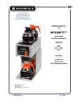
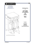
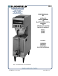
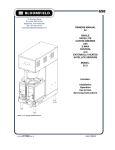
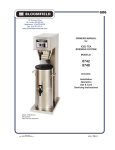
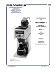
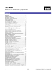
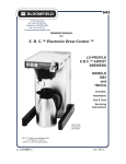
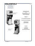
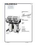
663
10 Sunnen Drive
St. Louis, MO 63143
telephone: 314-678-6336
fax: 314-781-2714
www.bloomfieldworldwide.com
OWNERS MANUAL
for
SATELLITE
COFFEE BREWER
with
ELECTRO-MECHANICAL
CONTROL
and
EXTERNALLY HEATED
SATELLITE SERVER
MODEL:
9102A
9104A
Includes:
Installation
Operation
Use & Care
Servicing Instructions
Model 9102A Satellite Brewer with 9105SS Satellite
p/n 2m-76061 Rev. D M663
090730
WARRANTY STATEMENT
All equipment manufactured by Bloomfield is warranted against defects
in materials and workmanship for the time periods listed in the chart
starting from the date the equipment is placed into service and is for the
benefit of the original purchaser:
THE FOREGOING OBLIGATION IS EXPRESSLY GIVEN IN LIEU
OF ANY OTHER WARRANTIES, EXPRESSED OR IMPLIED,
INCLUDING ANY IMPLIED WARRANTY OF MERCHANTABILITY
OR FITNESS FOR A PARTICULAR PURPOSE, WHICH ARE
HEREBY EXCLUDED.
BLOOMFIELD, LLC SHALL NOT BE LIABLE FOR INDIRECT,
INCIDENTAL OR CONSEQUENTIAL DAMAGES OR LOSSES
FROM ANY CAUSE WHATSOEVER.
Equipment
pour over, automatic coffee brewers
EBC, EMAX coffee brewers
* EBC, EMAX coffee brewer control
POD coffee brewers
ECO coffee brewers
coffee warmers
tea brewers
tea dispensers
tea dispenser BBTea
hot water machines
thermal servers
airpots
decanters
This warranty is void if it is determined that upon inspection by an
authorized service agency that the equipment has been modified,
misused, misapplied, improperly installed, or damaged in transit or by fire, flood or act of God.
Parts
2 yrs.
2 yrs.*
3 yrs.
1 yr.
1 yr.
1 yr.
2 yrs.
1 yr.
1 yr.
2 yrs.
90 days
30 days
no warranty
Labor
2 yrs.
2 yrs.
no labor
1 yr.
1 yr.
1 yr.
2 yrs.
1 yr.
no labor
2 yrs.
no labor
no labor
no warranty
It also does not apply if the serial nameplate has been removed or unauthorized service personnel perform service. The prices
charged by Bloomfield for its products are based upon the limitations in this warranty. Seller’s obligation under this warranty
is limited to the repair of defects without charge by a Bloomfield Authorized Service Agency or one of its sub-agencies. This
service will be provided on customer’s premises for non-portable models. Portable models (a device with a cord and plug or a
dispenser) must be taken or shipped to the closest authorized service agency, transportation charges prepaid, for services.
Agencies are located in principal cities, please visit our website to locate one.
This warranty is valid in the United States and Canada and void elsewhere. Please consult your classified telephone directory
or your food service equipment dealer; or, for information and other details concerning warranty, write to:
Service Parts Department; Bloomfield
10 Sunnen Drive, St. Louis, MO 63143
Phone: (314) 678-6336 : Fax: (314) 781-2714
Technical@ bloomfieldworldwide.com / www.bloomfieldworldwide.com
1. Resetting of safety thermostats, circuit breakers, overload protectors, or fuse replacements.
2. All problems due to operation at voltages other than specified on equipment nameplates - conversion to correct voltage
must be the customer’s responsibility.
3. All problems due to electrical connections not made in accordance with electrical code requirements and wiring diagrams
supplied with the equipment.
4. Replacement of items subject to normal wear, to include such items as knobs and light bulbs. Normal maintenance
functions including adjustment of thermostats, microswitches, and replacement of fuses and indicating lights are not
covered under warranty.
5. All problems due to inadequate water supply, such as fluctuating, or high or low water pressure.
6. All problems due to mineral/calcium deposits, or contamination from chlorides/chlorines. De-liming is considered a
preventative maintenance function and is not covered by warranty.
7. Full use, care and manuals may or may not be sent with each unit, only a condensed version. Please visit our web site to
download the full version.
8. Travel mileage is limited to fifty (50) miles from an authorized service agency or one of its sub-service agencies.
9. All labor shall be performed during normal working hours. Overtime premium shall be charged to the customer.
10. All genuine Bloomfield replacement parts are warranted for ninety (90) days from date of purchase on non- warranted
equipment. Any use of non-genuine Bloomfield parts completely voids any warranty.
11. Installation, labor and job checkouts are not considered warranty.
12. Charges incurred by delays, waiting time or operating restrictions that hinder the service technicians ability to perform
services are not covered by warranty. This includes institutional and correctional facilities.
SHIPPING DAMAGE CLAIMS PROCEDURE
NOTE: For your protection, please note that equipment in this shipment was carefully inspected and packaged by skilled
personnel before leaving the factory. Upon acceptance of this shipment, the transportation company assumes full responsibility
for its safe delivery.
IF SHIPMENT ARRIVES DAMAGED:
1. VISIBLE LOSS OR DAMAGE: Be certain that any visible loss or damage is noted on the freight bill or express receipt,
and that the note of loss or damage is signed by the delivery person.
2. FILE CLAIM FOR DAMAGE IMMEDIATELY: Regardless of the extent of the damage.
3. CONCEALED LOSS OR DAMAGE: if damage is unnoticed until the merchandise is unpacked, notify the
transportation company or carrier immediately, and file “CONCEALED DAMAGE” claim with them. This must be done
within fifteen (15) days from the date the delivery was made to you. Be sure to retain the container for inspection.
Bloomfield cannot assume liability for damage or loss incurred in transit. We will, however, at your request, supply you with the
necessary documents to support your claim.
663 p/n 2M-76061 Owners Manual Satellite Coffee Brewer
BLOOMFIELD SERVICE POLICY AND PROCEDURE GUIDE ADDITIONAL WARRANTY EXCLUSIONS
TABLE OF CONTENTS
WARRANTY STATEMENT xi
SPECIFICATIONS
1
FEATURES & OPERATING CONTROLS
2
PRECAUTIONS & GENERAL INFORMATION 4
AGENCY APPROVAL INFORMATION
4
INSTALLATION
5
OPERATION
7
CLEANING INSTRUCTIONS
9
TROUBLESHOOTING SUGGESTIONS
11
SERVICING INSTRUCTIONS
12
EXPLODED VIEW, BREWER
18
EXPLODED VIEW, SATELLITE
21
SERVICE KITS
22
WIRING DIAGRAM
23
Thank You for purchasing this
Bloomfield Industries appliance.
Proper installation, professional
operation and consistent
maintenance of this appliance will
ensure that it gives you the very
best performance and a long,
economical service life.
This manual contains the
information needed to properly
install this appliance, and to use,
care for and maintain or repair the
appliance in a manner which will
ensure its optimum performance.
SPECIFICATIONS
MODEL
VOLTS
WATTS
AMPS
POWER
SUPPLY
120 VAC 1ø
1790
15
4’ cord with NEMA 5-15P
9104A
115/230 VAC 1ø
4325
20
Requires 4-wire
(L1, L2, Neut + Gnd)
not provided
663 p/n 2M-76061 Owners Manual Satellite Coffee Brewer
9102A
1
FEATURES AND OPERATING CONTROLS
BREW HEAD
(brew chamber removed)
BREWER
Model 9102A
(model 9104A
is similar)
POUR-OVER
OPENING
LD
CONTROL
PANEL
IE
MF
OO
BL
BREW
HEAD
HOT WATER
FAUCET
®
SPOUT
BYPASS
NOZZLE
ON
F
OF
Y TO
AD
RE EW
BR
TIMER
ACCESS
ER
AT
HE
NK ITCH
SW
GASKET
TA
1/2
L
GA
1
L
GA
ME
LU
VO CTOR
LE
SE
ER
RM
H
WA
ITC
SW
EW
BR H
ITC
OP
ST
EW
BR
SW
BREW
CHAMBER
(IN POSITION)
BREWER
NAMEPLATE
SPRAY
DISK
WIRE
RACK
HI-LIMIT RESET
ACCESS (9104A)
METAL
BREW
CHAMBER
SATELLITE
(IN POSITION)
SATELLITE
WARMER
BREW CHAMBER
BREW-THRU LID
POWER CORD
(Model 9102A)
LID LATCH
ADJUSTABLE
LEG
HANDLE
REAR
VIEW
SIGHT
GLASS
SATELLITE
ELECTRICAL
INLET (9104A)
WATER SUPPLY
INLET
SERVING
FAUCET
OPTIONAL
DRIP TRAY
TERMINAL BLOCK
ACCESS
HOT
1/2
GAL
ON
READY TO
BREW
1
GAL
VOLUME
SELECTOR
WARMER
SWITCH
BREW
SWITCH
STOP
BREW
CONTROL
PANEL
TANK HEATER SWITCH
READY-TO-BREW INDICATOR
SELECT VOLUME SWITCH
SATELLITE WARMER SWITCH
BREW START SWITCH
Fig 1. SS-1 Satellite Brewing System
OFF
TANK HEATER
SWITCH
BREW CANCEL SWITCH
Features & Operating Controls
2
IL1844-M663
663 p/n 2M-76061 Owners Manual Satellite Coffee Brewer
POWER SWITCH
FEATURES AND OPERATING CONTROLS (continued)
Brewer
Adjustable Legs
Connector
Hot Water Faucet
Nameplate
Allows brewer to be leveled. Also allow clearance for cleaning
underneath brewer.
Connects to satellite. Allows satellite heater to be energized.
Allows brewer to sense that a satellite is in place.
Hot water dispensed here.
Lists manufacturer, model and serial number.
Also lists voltage and wattage rating of brewer.
Control Panel
Start Brew Switch
Press to start a brew.
Ready to Brew Indicator
Glows when water in tank is up to temperature.
Stop Brew Switch
Press to cancel a brew in progress.
Warmer Switch
Energizes satellite warmer.
Tank Heat Switch
Applies power to tank heater element. Glows when ON.
Volume Selector Switch
Allows selection of 1/2 gallon or 1 gallon brew (9102A); or,
1 gallon or 1-1/2 gallon brew (9104A).
Brew Chamber
Brew Chamber
Holds coffee grounds during brew cycle.
Wire Rack
Holds paper filter and coffee grounds in proper position in brew
chamber.
663 p/n 2M-76061 Owners Manual Satellite Coffee Brewer
Satellite
Brew-Thru Lid
Allows entry of brewed coffee and dilution water into satellite.
Minimizes splashing in the event satellite is tipped.
Handles
Allow the satellite to be safely carried.
Serving Faucet
Fresh coffee dispensed from satellite here.
Sight Glass
Check the level of coffee remaining here.
Drip Tray (optional)
Optional drip tray catches drips and spills from serving faucet.
Easily removed for cleaning.
3
GENERAL INFORMATION AND PRECAUTIONS
This appliance is intended for use in commercial establishments
WARNING:
only.
Electric
This appliance is intended to brew hot beverage, specifically coffee,
Shock hazard
All servicing requiring
access to non-insulated
electrical components must
be performed by a factory
authorized
technician.
DO NOT open any
access panel which
requires the use of tools.
Failure to follow this warning
can result in
severe electrical shock.
for human consumption. No other use is recommended or authorized
by the manufacturer or its agents.
Operators of this appliance must be familiar with the appliance use,
limitations and associated restrictions. Operating instructions must be
read and understood by all persons using or installing this appliance.
Cleanliness of this appliance is essential to good sanitation. Read and
follow all included cleaning instructions and schedules to ensure the
safety of the food product.
Surfaces of the brewer, brew chamber and satellite can be hot to the
touch, and may cause burns on contact.
Disconnect the brewer from electrical power before performing any
maintenance or servicing.
DO NOT submerge satellites in water.
CAUTION:
Burn Hazard
Surfaces of the brewer and
brew chamber may be hot
to the touch and can cause
burns on contact.
DO NOT splash or pour water over, onto or into any controls,
control panel or wiring.
Any procedure which requires the use of tools must be performed by a
qualified technician.
This manual is considered to be a permanent part of the appliance.
This manual and all supplied instructions, diagrams, schematics, parts
breakdown illustrations, notices and labels must remain with the
appliance if it is sold or moved to another location.
AGENCY APPROVAL INFORMATION
This dual satellite brewing system is
E9253
listed under E9253.
This dual satellite brewing system meets NSF Standard 4 only when
installed and maintained per the instructions in this manual.
STD 4
4
663 p/n 2M-76061 Owners Manual Satellite Coffee Brewer
This appliance is made in the USA. Unless otherwise noted, this
appliance has American sizes on all hardware.
INSTALLATION INSTRUCTIONS
INSTALL LEGS
The brewer is provided with adjustable legs. Be sure all four legs
are securely screwed into the base of the brewer.
LEVEL THE UNIT
The adjustable legs allow the brewer to be leveled. Set the brewer
in its ultimate operating location and check for level with a spirit
level Adjust the brewer for level from front-to-rear, and from sideto-side. Be sure all four feet rest firmly on the counter.
PLUMBER’S INSTALLATION INSTRUCTIONS
IMPORTANT:
This equipment must be installed in accordance with the Basic
Plumbing Code of the Building Officials and Code Administrators
International (BOCA), and the Food Service Sanitation Manual
of the Food and Drug Administration (FDA). Also, this equipment
installation must comply with all local plumbing codes and
ordinances.
CAUTION:
Hazard from
Unstable Equipment
Rubber feet must be installed
on each leg of the brewer. Legs
must be adjusted so that all four
feet rest firmly on the counter.
Failure to properly install the
feet can result in movement of
the brewer, which can cause
personal injury and/or damage
to the brewer.
IMPORTANT:
Brewer must be installed on a water line with a full-flow pressure
between 20 psi and 90 psi.
NOTE: If water pressure varies greatly, or exceeds 90 psi at any
time, a water pressure regulator must be installed. Plumbing
installer must supply the regulator.
Brewer must be connected to a potable water supply. Bloomfield
recommends not less than 1/4” copper tubing for installations of
12’ or less, and not less than 3/8” copper tubing for installations
exceeding 12’. Brewer must be connected to a COLD water line.
663 p/n 2M-76061 Owners Manual Satellite Coffee Brewer
NOTE: DO NOT use a saddle tap for this water line connection.
A shut-off valve must be installed between the main water supply
and the brewer. Plumbing installer must supply the shut-off valve.
A 1/4-turn ball valve is recommended.
Brewer INLET FITTING is 1/4” Male Flare.
IL1845
Fig. 3 Water Line Installation
Flush the water line before connecting to the brewer.
5
Fig. 2 Adjustable Legs
IMPORTANT:
In some areas, local codes
require a backflow preventer
(check valve) to be installed
on the inlet water line. If a
backflow preventer is used, you
must install a water hammer
arrester in the incoming line,
between the backflow preventer
and the brewer inlet, as far
away from the brewer as space
will allow. This will relieve the
excessive back pressures that
can cause faucet leaks and
solenoid malfunctions.
NOTE:
While new-style brewers
incorporate an internal strainer
in the inlet solenoid, the
provided “Y” strainer should be
installed in the incoming water
line for ease of servicing.
INSTALLATION INSTRUCTIONS (continued)
ELECTRICIAN’S INSTALLATION INSTRUCTIONS
CAUTION:
Electric Shock
Hazard
Brewer must be properly
grounded to a reliable earth
ground to prevent possible
shock hazard. Do not assume a
plumbing line will provide such
a ground. Electrical shock may
cause serious injury.
Refer to Electrical Specifications, page 1.
Brewer requires a dedicated single-phase circuit:
Model 9102A 120 Volt AC, 50/60 Hz 1ø 20 Amps
NEMA 5-15R receptacle
120/240 Volt AC, 50/60 Hz 1ø 30 Amps
3-Wire (L1, L2, Neutral) + Ground
Model 9104A
Fig. 4 Model 9104A Terminal Block
IMPORTANT:
Complete water line installation
before connecting brewer to
electrical power.
MAKE SURE THE FRONT
PANEL “TANK HEATER”
SWITCH IS IN THE OFF
POSITION BEFORE
CONNECTING BREWER TO
ELECTRICAL POWER.
DO NOT turn the TANK
HEATER switch ON until the
water tank is filled. Heating
element must be completely
submerged in water at all
times. Damage to the brewer
caused by operating the heating
elements dry is NOT covered by
warranty.
INITIAL SET-UP INSTRUCTIONS
Plumber’s and Electrician’s installation procedures must be
completed before proceeding with the set-up.
Be sure all electrical connections are secure, and that all
plumbing connections are secure and leak-proof.
1. CHECK BREWER FOR PROPER CONFIGURATION
Make sure spray disk gasket is in place INSIDE of spray head.
Make sure spray disk is properly installed.
Check hot water faucet for proper operation.
2. FILL WATER TANK
Be sure POWER SWITCH and TANK HEATER switch are OFF, then connect brewer to electric power.
Insert an empty brew chamber under the brew head. Place an empty satellite in position. Pour fresh cold water into the POUR-OVER OPENING until water flows from the brew basket.
3. CHECK HEATING
Turn POWER SWITCH ON, then press TANK HEATER switch ON. Water in tank will heat to brewing temperature in approximately 30 minutes. When the water temperature reaches the brew temperature setpoint, the READY-TO-
BREW light will glow.
Hold a suitable container under the HOT WATER FAUCET, then open the faucet . Continue drawing water until all trapped air is expelled.
6
663 p/n 2M-76061 Owners Manual Satellite Coffee Brewer
IMPORTANT:
Initial set-up must be performed
by a qualified installer or
qualified service technician.
Improper set-up will damage the
brewer and void the warranty.
OPERATING INSTRUCTIONS
Fig. 5 Control Panel
IL1846
BREWING COFFEE
Prepare the Brew Basket:
Make sure the wire rack is properly installed in the brew
chamber.
Insert one (1) Bloomfield paper filter into the brew chamber. Make sure the filter is properly supported by the wire rack.
Add a measured amount of grounds to the brew basket.
Recommendations (may vary, depending on type of coffee and personal taste preferences):
To brew 1/2 gallon, use 2.25 oz (64 gm) of coffee
To brew 1 gallon, use 4.50 oz (128 gm) of coffee
To brew 1-1/2 gallon, use 8.40 oz (240 gm) of coffee
Gently shake the basket to level the grounds.
Slide the brew chamber under the brew head.
663 p/n 2M-76061 Owners Manual Satellite Coffee Brewer
Insert the Satellite:
Slide satellite under the brew chamber until it is fully seated. Press WARMER switch ON.
(9102A) Select Brew Volume:
Press VOLUME SELECT switch to 1/2 GAL or 1 GAL
(9104A) Select Brew Volume:
Press VOLUME SELECT switch to 1 GAL or 1-1/2 GAL
Start the Brew:
Press the START BREW switch.
NOTE: The brew can be cancelled at any time by pressing the STOP BREW switch.
At the end of the brew, be sure all water has stopped dripping before removing the brew chamber.
When the READY-TO-BREW light comes on, the brewer is ready to run another brew cycle.
Empty the Brew Basket:
Discard the grounds and the paper filter. Rinse the brew chamber under clear water.
7
Fig. 6 Brew Basket
IMPORTANT:
To avoid overflows, DO NOT
start the brew cycle unless an
EMPTY satellite is in place
under the brew chamber.
NOTE: The brew can be
cancelled at any time by
pressing the STOP switch.
NOTE: DO NOT change the
VOLUME SELECT switch
during a brew. This will disrupt
the brew cycle.
CAUTION:
Burn Hazard
Basket and contents are hot to
the touch and may cause burns
on contact.
OPERATING INSTRUCTIONS (continued)
TANK VENT
TUBE
HOT WATER
FAUCET
FAUCET
SHUT-OFF
VALVE
BASIN
WATER
TANK
SOLENOID
BYPASS
BYPASS
VALVE
(9104A)
BREW
HEAD
TIMER
FAUCET
WATER
HEATING
COIL
BREW
CHAMBER
COLD WATER
HOT WATER
INLET FITTING
IL1847-M663
Fig. 7 Water Flow Diagram
The BYPASS is an
adjustable flow control
valve. It is adjusted to
taste for 1 and 1-1/2
gallon brews in Model
9104A
NOTE: Use of the faucet
will not affect the volume
of water delivered for a
brew. However, overuse of the faucet during
a brew may lower the
temperature of the brew
water.
BREW & BYPASS
This brewer is a standard displacement brewer with pour-over option.
For 9102A there is no bypass. Water admitted into the hot water tank
by the BREW SOLENOID will displace a like amount of heated water
through the brew head, brew chamber and into the satellite.
For 9104A, operation is identical to 9102A, except that a portion of the
heated water is diverted around the grounds in the brew chamber by a
BYPASS. Bypass water dilutes the brewed coffee, which, in the larger
volumes, would otherwise be too strong.
HOT WATER FAUCET
Water for the hot water faucet is heated in a coil inside of the water
tank. The faucet volume may be controlled by adjusting the FAUCET
NEEDLE VALVE. Hot water is delivered at inlet line pressure and is
approximately the same temperature as the brew water.
8
663 p/n 2M-76061 Owners Manual Satellite Coffee Brewer
The time the BREW
SOLENOID is open is
controlled by the TIMER
in response to the
position of the VOLUME
SELECTOR switch.
CLEANING
INSTRUCTIONS
CLEANING
INSTRUCTIONS
PROCEDURE: Clean Coffee Brewer
CAUTION:
Burn Hazard
PRECAUTIONS: Turn POWER SWITCH OFF.
Allow brewer to cool.
FREQUENCY: Daily
TOOLS: Mild Detergent, Clean Soft Cloth or Sponge
Bristle Brush
2. Remove satellite.
3. Remove and empty brew chamber.
4. Remove spray disk and gasket from spray head
5. Wipe inside of spray head and area around spray head with a
soft clean cloth or sponge moistened with clean water.
6. Wash spray disk in a sink using warm water and a mild
detergent. A bristle brush may be used to clear clogged spray holes. Rinse spray disks with clean water and allow to air dry.
7. Wash brew basket in a sink using warm water and a mild
663 p/n 2M-76061 Owners Manual Satellite Coffee Brewer
IMPORTANT:
DO NOT use steel wool, sharp
objects, or caustic, abrasive or
chlorinated cleansers to clean
the brewer, brew baskets or
satellites.
1. Turn POWER SWITCH OFF.
Allow brewer to cool.
Brewing and serving
temperatures of coffee are
extremely hot. Hot coffee will
cause serious skin burns.
detergent. A bristle brush may be used to clean around the wire racks and bypass channels. Rinse with clean water and allow to air dry. Be sure wire rack is properly installed.
8. Remove and drain the drip tray. Rinse in a sink under warm running water. Allow to air dry, then reinstall on brewer.
9. Wipe exterior of brewer and satellites with a soft clean cloth or sponge moistened with clean water.
10. Reinstall gasket INSIDE brew head, then reinstall spray disk.
11. Reinstall brew chamber.
12. Reinstall satellite.
Procedure is complete
9
DO NOT immerse or submerge
satellites in water.
CLEANING INSTRUCTIONS (continued)
Brewing and serving
temperatures of coffee are
extremely hot.
Hot coffee will cause
serious skin burns.
IMPORTANT:
DO NOT use steel wool, sharp
objects, or caustic, abrasive or
chlorinated cleansers to clean
the satellites.
PROCEDURE: Clean Satellite
PRECAUTIONS: Drain Satellite before Cleaning
FREQUENCY: Twice Weekly
TOOLS: Sight Glass Brush, Sanitizer
Soft Clean Cloth, Bucket
1. Remove and drain satellite.
2. Place 1 packet of Sanitizer into 2-1/2 gallons of warm tap
water. Pour approximately 1 gallon of sanitizer solution into each satellite. Allow to stand for 2 minutes.
3. Remove the shield cap (large vent) on top of the sight glass.
NOTE: It is not necessary to remove the sight glass unless it is broken and replacement is required.
4. Run the sight glass brush up and down through the sight glass at least 10 times.
5. Reinstall and tighten the shield cap.
6. Drain sanitizer solution from satellite into the bucket.
7. Disassemble faucet. Brush clean with sanitizer solution.
Reassemble faucet.
8. Install satellite on brewer.
9. Rinse satellites: With an empty brew chamber in place,
press the BREW key and run 1 full cycle into satellite.
10. Drain water from satellites.
Procedure is complete
10
663 p/n 2M-76061 Owners Manual Satellite Coffee Brewer
CAUTION:
Burn Hazard
TROUBLESHOOTING SUGGESTIONS
SYMPTOM
SUGGESTED REMEDY
Reconnect brewer to electric power Reset
circuit breaker
Main power switch off or damaged
Check. Turn main power switch on.
Replace if needed
Brew switch damaged
Check. Replace if needed
Timer damaged
Check. Replace if needed
Volume selector switch damaged
Check. Replace if needed
Tank heat switch off
Turn tank heat switch on
Hi-limit tripped
Allow to cool, reset hi-limit
Thermostat out of adjustment or damaged
Check. Adjust or replace as needed
Switch not pressed long enough or firmly
enough
Switch must be pressed firmly for at least 1
second
Stop Brew switch damaged
Check. Replace if needed
Brew solenoid damaged or dirty
Check. Clean or replace as needed
Too much coffee or too fine a grind
Use proper amount and grind of coffee
grounds per brew
More than 1 filter paper or wrong type of
filter paper used
Use 1 genuine Bloomfield filter paper per
brew
Timer out of adjustment or damaged
Check time. Adjust or replace as needed
Wire rack missing from brew chamber
Check. Replace if needed
Low inlet water pressure
Other appliances on water line may be
robbing pressure. Brewer should be on
dedicated water line
Inlet or valve strainer plugged
Clean strainer
Timer out of adjustment
Adjust time
Timer damaged
Check. Replace if needed
Ready light does not glow
Light damaged
Check. Replace if needed
Poor spray pattern from spray
disk
Spray disk holes plugged
Check. Clean as needed
Gasket missing or improperly installed
Reinstall gasket inside brew head
Will not heat or brew (no lights)
Will not brew
Brewer fails to heat
Brewer fails to stop brewing after
STOP switch is pressed
Coffee overflows from brew
chamber
663 p/n 2M-76061 Owners Manual Satellite Coffee Brewer
POSSIBLE CAUSE
Brewer not plugged in or circuit breaker
tripped
Insufficient brew volume
(all volumes)
Poor coffee quality
Keep brewer and satellites clean. Install a taste and odor filter in water supply, and replace
cartridges regularly. Use a quality coffee with a consistent roast. Use proper grind and
amount of coffee per brew.
11
SERVICING INSTRUCTIONS
Disconnect brewer from electric
power before opening any
access panel.
Note position of any wires or
hoses before removing them
from a panel.
Wrench for Faucet Tubing
ACCESS PANELS
TOP PANEL is attached with two screws at the rear and a lip at
the front.
TOP REAR PANEL is attached with four screws.
BASIN sets in the body. After disconnecting three hoses, it may
be lifted out.
TIMER ACCESS and HI-LIMIT ACCESS PLUGS may be pried
out with a thin flat blade screwdriver.
FRONT PANEL is attached with four screws.
SATELLITE WARMER PANEL is held by two spring clips.
After removing the front panel, slide the warmer panel forward
approximately 1/2” to release.
SATELLITE BRACKET is attached with two screws
BOTTOM PANEL is attached with six screws.
LEGS screw into the bottom panel.
TOP PANEL
TOP REAR
PANEL
BASIN
BODY
D
IEL
MF
OO
BL
®
ON
OFF
TO
DY
REA W
BRE
1/2
GAL
1
GAL
E
UM
VOL OR
ECT
ER
RM
H
WA
ITC
SW
W
BRE H
ITC
TER
K HEA H
TAN ITC
SW
P
STO
W
BRE
SW
SEL
FRONT
PANEL
TIMER
ACCESS
HI-LIMIT
ACCESS
SATELLITE
BRACKET
BOTTOM
PANEL
LEGS
SATELLITE
WARMER
IL1848_M663
12
663 p/n 2M-76061 Owners Manual Satellite Coffee Brewer
CAUTION:
SHOCK HAZARD
SERVICING INSTRUCTIONS (continued)
TEMPERATURE ADJUSTMENT
CAUTION:
SHOCK HAZARD
PRECAUTIONS: Disconnect brewer from electric power.
Allow brewer to cool.
FREQUENCY: As required to adjust delivered volume
TOOLS: Phillips head screwdriver
Live electrical circuits are
exposed during this procedure.
Use care to avoid uninsulated
electrical connectors.
Adjustments to be performed by
qualified technician only.
1. Press HEATER ON/OFF switch to OFF. Turn POWER switch on back of brewer OFF.
2. Remove TOP PANEL. Operating controls are accessible through the top panel only.
3. Remove vent tube from the tank cover and insert a
thermometer of known accuracy.
4. Locate the CONTROL THERMOSTAT on the right side of the top housing
Turn CLOCKWISE to increase temperature
Turn COUNTER-CLOCKWISE to decrease temperature
1/8 turn is equal to approximately 10ºF change.
5. Turn POWER switch ON. Press TANK HEATER switch to ON.
6. Allow the brewer to come up to brewing temperature. When READY-TO -BREW light comes on, check temperature on thermometer. Readjust thermostat as necessary.
BOILING
POINT OF
WATER
TEMP ( F)
210
205
IDEAL
BREWING
TEMPERATURE
200
195
MAXIMUM
TEMPERATURE
SETTING
190
ELEVATION (feet above sea level)
IL1601
BOILING
POINT OF
WATER
100
TEMP ( C)
97
IDEAL
BREWING
TEMPERATURE
94
91
MAXIMUM
TEMPERATURE
SETTING
0
05
0
1,
20
1, 0
35
0
1,
50
1, 0
65
0
1,
80
1, 0
95
0
1,
90
75
0
88
0
15
0
30
0
45
0
60
0
663 p/n 2M-76061 Owners Manual Satellite Coffee Brewer
7. When desired temperature is achieved, remove thermometer, replace vent tube and reinstall top panel.
ELEVATION (meters above sea level)
IL1602
Procedure is complete
13
NOTE:
1/8 turn = approx 10ºF (5.5ºC)
SERVICING INSTRUCTIONS (continued)
Adjustments to be performed by
qualified technician only.
NOTE:
Brewer is pre-adjusted to deliver
1/2, 1 and/or 1-1/2 gallons of
coffee at a water pressure of
50 p.s.i. Use this procedure to
adjust the delivered volume to
suit local conditions.
BREW TIMER ADJUSTMENT
PRECAUTIONS: None
FREQUENCY: As required to adjust delivered volume
TOOLS: Small flathead screwdriver
Satellite or other container to calibrate volume
1. Press TANK HEATER switch to OFF.
3. Install an empty satellite and empty brew chamber.
4. Press START BREW switch. Brew should deliver 1 gallon (128 fl. oz.). If adjustment is necessary, turn TIMER knob:
Turn CLOCKWISE to increase time;
Turn
COUNTER-CLOCKWISE to decrease time.
Test after each adjustment. Be sure to empty satellite before each test.
5. Turn TANK HEATER switch ON.
6. Allow the brewer to come up to brewing temperature, then perform a test brew. Check delivered volume. Readjust as necessary.
7. Reinstall TIMER ACCESS COVER.
When desired volume is achieved, procedure is complete.
14
663 p/n 2M-76061 Owners Manual Satellite Coffee Brewer
Adjust only in small increments
to avoid large volume variations.
Recommend knob be turned no
more than one mark on the dial
plate at a time.
Moving the dial one mark will
change delivered volume by
approximately 6 oz.
2. Remove TIMER ACCESS COVER on front panel. Press VOLUME SELECTOR to 1 GAL position.
SERVICING INSTRUCTIONS (continued)
BYPASS ADJUSTMENT (9104A ONLY)
CAUTION:
SHOCK HAZARD
PRECAUTIONS: Disconnect brewer from electric power.
Allow brewer to cool.
FREQUENCY: As required to adjust for change in delivered volume, or to taste.
TOOLS: Phillips head screwdriver
Stubby flathead screwdriver
Provided wire gauge set
1. Press TANK HEATER switch to OFF. Disconnect brewer from electrical power.
2. Remove SATELLITE, BREW CHAMBER, TOP PANEL and BASIN.
3. Turn bypass adjustment screw several turns counter-
clockwise. Insert and hold appropriate gauge fully into
bypass valve from the outside of the brewer.
4. Turn bypass adjustment screw clockwise until the resistance of the adjuster contacting the gauge is felt.
5. Release the gauge set. Turn bypass adjustment screw counterclockwise slowly until gauge set fall out of the valve.
663 p/n 2M-76061 Owners Manual Satellite Coffee Brewer
6. Reassemble brewer and perform a 1 gallon brew and sample for taste. Adjust from this point to achieve desired taste:
a. Repeat steps 1 and 2.
b. Turn bypass adjustment screw counterclockwise to decrease coffee strength (increase dilution); or , clockwise to increase coffee strength (decrease dilution).
7. Perform BREW TIMER ADJUSTMENT to insure delivery of 128 oz. in 1 gallon mode.
Procedure is complete
15
Disconnect brewer from electric
power before opening the top
panel.
The brewer is shipped from the
factory pre-set for 25% bypass.
This adjustment must never
be made unless the brewer is
installed on a soft water line, or
a change in coffee strength is
required.
Bypass Gauge Set
Bypass Adjustment
SERVICING INSTRUCTIONS (continued)
Deliming chemicals are caustic.
Wear appropriate protective
gloves and goggles during this
procedure.
Never siphon deliming
chemicals or solutions by
mouth.
This operation should only be
performed by qualified and
experienced service personnel.
PROCEDURE: Delime the Water Tank
PRECAUTIONS: Disconnect brewer from electric power.
Allow brewer to cool.
FREQUENCY: As required (Brewer slow to heat)
TOOLS: Deliming Solution
Protective Gloves, Goggles & Apron
Mild Detergent, Clean Soft Cloth or Sponge
Bristle Brush, Bottle Brush
Large Sink (or other appropriate work area)
IMPORTANT: DO NOT spill,
splash or pour water or deliming
solution into or over any internal
component other than the inside
of the water tank.
1. Disconnect brewer from the electrical supply.
2. Remove the brewer top panel, then remove the tank lid assembly. Do not disconnect the tank assembly at this time.
3. Siphon all water from the hot water tank.
IMPORTANT: DO NOT allow
any internal components to
come into contact with the
deliming solution. Take care to
keep all internal components
dry.
NOTE: Repeat steps 4 and 7
as required to remove all buildup.
4. Mix 2 gallons of deliming solution according to the
manufacturer’s directions. Carefully pour the deliming solution into the water tank. Lower the lid assembly back onto the tank. Allow to sit for 30 minutes, or as directed by the chemical manufacturer.
5. At end of soaking period, reconnect brewer to electrical power. Install the brew chamber without filter paper or grounds. Place an empty satellite under the brew
chamber. Force a 1-1/2 gallon brew:
a. Press the 1-1/2 gallon key
b. Press the brew key, then press and hold the brew key until a brew is initiated.
Empty the satellite and repeat for the other side.
6. Disconnect brewer from electrical power and allow to cool.
7. Remove lid assembly from tank.
a. Using a stiff bristle brush, scrub internal components to remove lime and calcium build-up.
b. Thoroughly rinse internal components of lid assembly with clear water.
c. Store lid assembly in a safe location.
8. Using a stiff bristle brush, scrub exposed portions of the heating element and the inside surfaces of the tank to
remove lime and calcium build-up.
9. Siphon all solution from the tank.
16
663 p/n 2M-76061 Owners Manual Satellite Coffee Brewer
CAUTION:
CHEMICAL BURN
HAZARD
SERVICING INSTRUCTIONS (continued)
10. Reinstall tank lid assembly into hot water tank. Make sure the lid gasket is properly in place, then reinstall the hold-
down clamp.
11. Remove spray disks and gaskets. Rinse both brew heads with clean water. Using a stiff brush, scrub spray disk to remove any lime or calcium build-up. Reinstall gaskets and spray disks.
13. Reconnect brewer to electrical supply .
14. Install the brew chamber without filter paper or grounds.
15. Place an empty satellite under the brew chamber. Run
at least five 1 gallon brew cycles and discard all water generated at the end of each cycle.
Repeat for the other side.
16. Rinse satellite with clean water. Reinstall empty satellite under brew chamber.
663 p/n 2M-76061 Owners Manual Satellite Coffee Brewer
Brewer is ready to use.
17
NOTE: Normally, silicone
hoses do not need to be
delimed. Should deliming hoses
become necessary, Bloomfield
recommends replacing the
hoses.
EXPLODED VIEW: 9102A, 9104A
PLUMBING COMPONENTS
25
15
OLD-STYLE
1
17
26
16
27
28
2
29
3
30
4
TUBE, FAUCET
SUPPLY
18
5
6
19
7
21
8
31
20
32
22
33
23
9
34
10
11
35
24
38
36
12
37
13
14
39
40
41
TANK ASSEMBLY
44
52
42
53
42
45
46
48
55
54
56
47
57
49
58
59
50
51
60
61
PL663
IL1849 REV. A 7/29/09
18
663 p/n 2M-76061 Owners Manual Satellite Coffee Brewer
43
PARTS LIST: 9102A, 9104A
PLUMBING COMPONENTS
663 p/n 2M-76061 Owners Manual Satellite Coffee Brewer
Fig No
Part No
Description
Fig No
1
2
DD-75778
HOSE BRADED W/BALL VLV
3
DD-71099
ELBOW 1/4 FPT/HOSE
4
5
2V-70124
VALVE SOLENOID 120V
6
DD-70122
TEE BRS 3/8NPTX7/16-20X7/16-20
7
8
9
10
11
12
13
14
15
16
17
2E-75685
2V-73027
2V-70111
2C-70155
SOLENOID BYPASS 120V
STRAINER ‘Y’ PLASTIC W/FT
TUBE FORMED INLET ASSY
NUT 7/16-20 HEX HD BRASS
2K-70154
2V-76056
DD-71357
FTG UNION 1/4X1/4
TUBE 1/4IDX5.9X2.90 FLARE
TUBE ASSY INLET
2E-70451
18
DD-70158
19
20
21
22
23
24
25
26
27
28
29
30
31
32
DD-71389
DD-71387
CONNECTOR BRASS
TUBE OUTLET WATER 7
1/4 L
TUBE T BYPASS ASSY
TUBE SIL .312ID X .69
DD-70878
2C-70874
DD-70938
2V-70398
D7-71300
2K-70096
M3-71258
2K-70883
2K-70103
2K-70130
A6-70163
VALVE, BYPASS
SCREW(CHI)3/8-24X3/4 SL
KIT BYPASS SET
TUBE VENT LONG
PAN BASIN 9102
ELBOW POLYPROPELYNE
TUBE SIL .375 ID X 19
ELBOW INLET
ELBOW OUTLET
ELBOW SPRAYER
RETAINER HEAD SPRAY
9102A
9104A
19
Part No
Description
33
2I-70139
GASKET SPRAY HEAD
34
A6-72727
SPRAY HEAD DISC EMBOSSED
35
2C-72680
NUT 7/16-20 FINISHED HEX JAM
36
37
38
39
40
41
2C-70107
2C-72681
WS-82556
WS-82573
WS-82682
WS-82575
42
WS-84804
43
44
45
46
47
48
49
50
51
52
53
54
55
56
57
58
59
60
61
2C-70135
2C-70133
WASHER LOCK 7/16 EXT SEMS
WASHER FLT 15-32X1 1/8
FAUCET ASSY PRESSURE N/S
HANDLE RED FAUCET
CLIP FAUCET
SEAT CUP FAUCET N/S
KIT STREAM FORMER PRESS
FAUCET
SCREW 10-32X1 PH PAN HD
NUT 8-32 HEX ACORN SS
2D-71382
A6-70142
2I-70147
2I-70152
TANK BODY WELDED ASSY
COVER TANK S/A A/F
GASKET TANK COVER
GASKET ELEM HTG
2N-70149
2C-70134
2C-73457
2C-70175
WS-8512-51
2A-77260
2C-70146
2C-70145
2V-70884
2N-70520UL
WS-8760-44
COIL ASSY HOT WATER
STRAP HOLD DOWN ASSY
NUT 8-32 HEX ACORN SS
NUT 1/2-20 HEX HD BRASS
T-STAT COTHERM SUBST 851
SLEEVE THERMOSTAT BULB 11.00
NUT 4-40 HEX HD MS SS
SCREW 4-40X1-1/2 SL PAN
TUBE WATER INLET
ELEM HEATING 120V 1675W 9102A
ELEM 240V 4200W
9104A
EXPLODED VIEW: 9102A, 9104A
ELECTRICAL COMPONENTS
1
9102A
2
3
11
12
13
4
5
14
15
6
16
7
14
17
8
18
9
19
10
20
21
9104A
1
11
12
663 p/n 2M-76061 Owners Manual Satellite Coffee Brewer
22
13
23
5
14
15
16
6
14
17
7
18
25
8
26
19
20
21
PL663
20
IL1850 REV. A 7/29/09
PARTS LIST: 9102A, 9104A
ELECTRICAL COMPONENTS
Fig No.
Description
WS-86280
2T-47499
2E-70642
2N-70520UL
2V-70124
2P-71309
2E-70709
2E-75685
2K-70215
2E-70353
2C-70175
2I-70152
2A-77260
2E-70411
2J-72671
2E-70435
DD-70031
2E-71308
2N-70091UL
T-STAT COTHERM SUBST 851
THERMO HI-LIMIT 120/240V
SWITCH TOGGLE
ELEM HEATING 120V 1675W
VALVE SOLENOID 120V
TIMER 3 LEVEL 120V
TERM BLOCK 4 POLE
SOLENOID BYPASS 120V .75GPM
STRAIN RELIEF STR HEYCO
CORD & CAP ASSY 120V 15A
NUT 1/2-20 HEX HD BRASS
GASKET ELEM HTG
SLEEVE THERMOSTAT BULB
SWITCH ON-OFF LITED RED
LIGHT PILOT GREEN 125V
SWITCH MOMENTARY NC 125/2
SWITCH BLACK BREW 125V10
SWITCH VOL SELECT 125/250
ELEM WARMER 120V 100W
2E-30330
WS-8760-44
2E-70395
2T-70716
A6-70741
SWITCH ON OFF TOGGLE 20A
ELEM 240V 4200W
SWITCH ROCKER 240V 20A
THERMO HI-LIMIT RESET 240
BRKT HI-LIMIT
663 p/n 2M-76061 Owners Manual Satellite Coffee Brewer
1
2
3
4
5
6
7
8
9
10
11
12
13
14
15
16
17
18
19
20
21
22
23
24
25
26
Part No.
21
9102A
9104A
EXPLODED VIEW: 9102A, 9104A
CABINET & RELATED COMPONENTS
1
16
2
17
3
18
4
19
5
20
6
21
22
23
7
8
25
26
27
9
10
28
11
12
13
14
15
PL663
22
IL1851 REV. A 7/29/09
663 p/n 2M-76061 Owners Manual Satellite Coffee Brewer
24
PARTS LIST: 9102A, 9104A
CABINET & RELATED COMPONENTS
Fig No
Part No
Description
2F-76666
FILL PORT ASSY BREWERS PLASTIC
4
D7-71300
PAN BASIN 9102
5
D7-71358
BASIN BODY ASSY 9102 DRWG
1
2
3
9102A
5
9104A
6
9102A
6
9104A
7
8
DD-72485
PLUG HEYCO DOUBLE D BULK MATTE
9
DD-71305
COVER BASE BACK
10
DD-71222
BRKT FAUCET SUPPORT
11
DD-71302
BASE COVER WELD S/A 9102
12
DD-72297
BOTTOM PLATE SUB ASSY
14
2A-70631
LEG BLACK 4X1/4-20
15
WS-3902
TRAY DRIP SS1
16
2B-70466
RACK WIRE BREW CHAMBER
17
2D-71338
CHAMBER BREW DIMPLE
18
2C-70467
CLIP BREW BASKET
19
2R-70112
HANDLE BLACK
663 p/n 2M-76061 Owners Manual Satellite Coffee Brewer
13
20
2M-71314
DECAL 9102 BASIN
9102A
20
DD-71390
DECALS 9104 BASIN(OBS)
9104A
22
2P-70053
PLUG BUTTON 2IN
23
2C-70314
NUT 6-32 KEPS MS SS
24
A6-70741
BRKT HI LIMIT
25
2P-70275
PLUG BUTTON 3/8 DIA
26
2C-70132
NUT TNR ZI #8
27
2C-70092
SCREW 8BX3/8 PH PAN HD SM
21
28
10-32 X 1/4” SCREW
23
EXPLODED VIEW (continued)
SATELLITE ASSEMBLY 9105SS
1
2
3
4
6
8
23
5
7
22
9
10
21
11
12
13
14
663 p/n 2M-76061 Owners Manual Satellite Coffee Brewer
20
15
16
19
17
18
Model: 9105SS
PL663
IL1852 REV. A 7/30/09
24
PARTS LIST: 9102A, 9104A
663 p/n 2M-76061 Owners Manual Satellite Coffee Brewer
Fig No
1
2
3
4
5
6
7
8
9
10
11
12
13
14
15
16
17
18
19
20
21
Part No
DD-71723
2C-70.379
2C-71363
D7-71376
DD-71351
WS-8600-17
WS-8700-25J
WS-8705-11C
WS-8600-20
DD-8705-11L
2U-71460
WS-8705-11B
WS-8705-11G
WS-8600-26
WS-8600-27
2U-71345
WS-8600-24
DD-71344
22
23
Description
COVER ASSY SATELLITE CTR
SCREW 8-32X5/16 PH PAN MS
WASHER BELLEVILLE
BRKT LATCH SAT COVER
WASHER NYLON
BRKT FAUCET GUARD
CAP SHIELD VENT HL
WASHER UPPER TUBE
TUBE SIGHT GLASS 10IN
SHIELD 10 GUAGE
ASSY UPPER W/SEAT CUP
SEAT CUP TEA DISP FAUCET
WASHER 79ES GASKET W/1/16
SHIELD BASE
C RING
NUT WNG #17 ANYB
FAUCET BODY
FAUCET SIGHT-GLASS 10IN
SHANK
BUSHING
HANDLE RECESSED
BODY AND TANK ASSY
DD-71362
SCREW 8-32 AISI 303 SPEC
25
SERVICE KITS
FAUCET REPAIR COMPONENTS
2C-72680
Hex Lock Nut
2C-70107
7/16“ Lock Washer
2C-72681
Washer
WS-82556
Faucet Assembly
LOCKNUT
LOCK WASHER
WASHER
FAUCET ASSY
HANDLE
RETAINER CLIP
SPRING
SEAT CUP
WS-82682
WS-84804
WS-84870
SOLENOID REPAIR KITS
2E-75685
WS-85218
WS-85219
Handle
Seat Cup
Faucet Repair Kit (Includes Handle, Seat Cup, Spring,
Stem, Pin & Bonnet
Retainer Clip
Aerator Replacement Kit (Includes O-Ring,
Aerator Disk & Aerator Cap
Aerator Repair Kit (Includes O-Ring & Aerator Disk)
O-RING
AERATOR DISK
AERATOR CAP
STEM
PIN
BONNET
STRAINER
WASHER
Solenoid, Complete, with Bypass
Inlet Fitting Kit (cap, inlet fitting, washer & strainer)
Inlet Strainer
INLET FITTING
CAP
IL1854 PL663
663 p/n 2M-76061 Owners Manual Satellite Coffee Brewer
FAUCET REPAIR KITS
WS-82573
WS-82575
WS-82576
26
663 p/n 2M-76061 Owners Manual Satellite Coffee Brewer
WIRING DIAGRAMS
27
663 p/n 2M-76061 Owners Manual Satellite Coffee Brewer
NOTES
663 p/n 2M-76061 Owners Manual Satellite Coffee Brewer
NOTES
10 Sunnen Drive, St. Louis, MO 63143
telephone: 314-678-6336 fax: 314-781-2714
www.bloomfieldworldwide.com