1
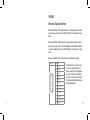
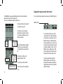
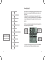
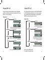
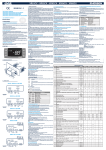
Bulkhead Installation
●
●
●
●
●
●
●
24
Decide on a location.
Allow adequate clearance behind the
unit for the cable connection to ensure the cable is not unduly stressed.
Ensure that there is sufficient length of cable to remove unit for servicing purposes.
Using the supplied template as a guide, cut out the hole for the back and drill four
4.3 mm (0.170”) holes for the studs.
Screw the four M4 studs into the rear of the unit.
Connect the cable into the rear of the unit.
Place the unit in position, then secure it by screwing the thumb nuts onto the studs.
Electronic Display
ED-3
User’s Guide
Engine Monitor
APPENDIX
Electronic Display Connections
When using SAEJ1708/ J1587 communication protocol the display requires four wires to
operate: two for power and two for the SAE J1587 databus. Pin assignments are shown
below.
When using SAEJ1939 communication protocol, again the display requires four wires to
operate: two for power and two for the J1939 databus. However the SAEJ1939 databus
connections are different to those of the SAEJ1587 databus. Pin assignments are shown
below:
Vehicle speed input from a GPS or speed transducer can be input to the display.
15.
GEMpinconnection
- continued
Connector
out
Signaldata
Notes
Connector pin out
1
Ground
21
Keyswitch
Ground
32
NMEA
TX (+)
Keyswitch
43
NMEATX
TX(-)(+)
NMEA
54
NMEARX
TX(-)(-)
NMEA
5
NMEA RX (+)
Signal
6
6
NMEA RX (-)
NMEA RX (+)
7
CAN LO (J1939 LO)
8
CAN HI (J1939 HI)
99
J1708/J1587+
J1708/J1587 +
10
10
J1708/J1587J1708/J1587 -
11
11
ExternalAlarm
AlarmOutput
Output
External
12
12
NotUsed
Used
Not
7
8
2
Notes
Note that pin 11 of the connector can be
used to drive an external alarm. To do
this, wire a switched +12 volt supply wire
to one side of the alarm, and the other to
pin 11 of the connector from the display.
The external alarm will activate whenever
the display alarm bleeps.
CAN LO
CAN HI
23
DATA LINK INFO
(when Data Type is J1939)
J1939 VIEWER Allows user to view J1939 raw messages
received by the Display.
NMEA VIEWER Allows user to view NMEA raw messages
received by the Display.
Use the ADJUST key (key 4) to enter the Data Link Info screen.
Use the up/down scroll keys (keys 1 and 2) to move the pointer
to the desired selection followed by the ADJUST key (key 4) to
enter the screen and view the data.
Use the BACK key (key 5) to return to the Data Link Info menu.
RPM Menu
Allows the user to select rounding of the RPM value. Choices are rounding to the nearest
10’s, nearest 5’s, or nearest 1’s. The default value is set to the nearest 10’s. Values are
changed using the ADJUST key.
22
Table of Contents
Electronic Display Description
4
Power On Screen
5
Initial Setup
6
Default Screen (BASIC PAGE)
8
Changing the engine parameter to be viewed 9
Navigation between pages
11
View group (VIEW – Key 1)
12
Trip Group (TRIP Key 2)
13
Display Group (DISP – Key 3)
14
Alarm Page (Key 5)
15
Menu Exit (MENU EXIT – Key 5)
17
Configuration Menu
18
User Menu
18
Setting Menu
19
Alarm History
19
System Menu
20
DATALINK Menu
21
RPM Menu
22
APPENDIX
23
Electronic Display Connections
23
Bulkhead Installation
24
3
Electronic Display Description
The ED-3 Electronic Display is an LCD display with 5 menu keys that can display engine
parameters in a variety of formats. Display formats are: basic, analog gauge, graphical, text,
and quad display. The Electronic Display receives engine data from an industry standard
SAE J1708/J1587 or J1939 datalink. Displayable engine parameters will vary with the
engine application, but typically include engine speed, throttle position, system voltage, and
engine load.
Boat speed can also be displayed for some engine applications if a Global Positioning
System (GPS) or a speed transducer is connected on the RS422 receive (RX) input. See the
appendix for connector pinout information.
DATALINK Menu
ENGINE
DATA TYPE
DATA LINK INFO
(when Data Type is J1587)
J1939 SETTINGS
(when Data Type is J1939)
4
Selects the engine model that is connected to the display. Choices
include QSB, QSC, QSM11, QSX, QSK, QST30, 480C-E, M11ECMC,
N14ECMC, and CENTRY. Use the ADJUST key (key 4) to enter the
Setting Menu then use up/down scroll keys (keys 1 and 2) to move
the pointer to the desired engine model. Press the SELECT
key (key 4) to fill in the box in the right hand column adjacent to
the desired model, then press the BACK key (key 5) to return to the
Datalink Menu.
Selects Data type (J1939 or J1587). Use the ADJUST key (key 4) to
desired setting.
J1587 INFO Allows user to view J1587 message data
J1587 VIEWER Allows user to view J1587 raw messages received
by the Display.
NMEA VIEWER Allows user to view NMEA raw messages received by
the Display.
Use the ADJUST key (key 4) to enter the Data Link Info screen. Use
the up/down scroll keys (keys 1 and 2) to move the pointer to the
desired selection followed by the ADJUST key (key 4) to enter the
screen and view the data.
Use the BACK key (key 5) to return to the Data Link Info menu.
Allows user to configure engine source to suit the configuration of
the installation. Choices include 1 (Actual SA 00), 2 (Actual SA 01),
3 (Actual SA 242), 4 (Actual SA 243), 5 (Actual SA 244) and 6 (Actual
SA 245). Use the ADJUST key (Key 4) to enter the J1939 Settings
screen. Use the ADJUST key (Key 4) to select the desired setting,
press the BACK key (Key 5) to return to the Data- Link Menu.
21
Power On Screen
System Menu
Note: This menu was designed for use by Cummins service personnel. Incorrect use of
these features can cause problematic operation.
DEMO
RESET ALL
UPLOAD
ABOUT
Turns the display demo mode on or off.
This mode is not intended for normal usage.
Resets the Engine Data Display module to the factory default
settings.
Allows the unit to be reprogrammed when selected.
Summarizes display running mode information.
This power on screen will be shown when power is first applied to the unit. The display will
perform a self-test for proper operation of the datalink, flash, RAM and LCD. A progress
bar gives a general indication of how far the self-test has progressed. The display also
indicates the current user for whom the display is configured.
Engine Configuration,
Comms Protocol and
Engine source
Software Version
Shows the current user
for whom the display is
configured
20
Bar indicating how far the
self-test has progressed
Parameters tested by the
display
5
Initial Setup
On initial power up the display will automatically enter screens within the Settings and
Config Menus which need to be set up by the user in order to use the display. Once these
are set on the initial power-up, it is not necessary to repeat these steps. If the initial settings
have been set incorrectly, the setup screens can be corrected via the Configuration Menu
(see Configuration Menu section).
The user is first prompted to select the engine
model to which the display is connected.
Key 1
Key 2
Key 3
Key 4
Key 5
Use up/down scroll keys (Key 1 or Key 2)
to move the pointer to the desired engine
model. Press the SELECT key (Key 4) to
fill in the box in the right hand column
adjacent to the desired model, then press
the BACK key (Key 5).
6
The display then enters the Data-link
screen and the user should select Data
type, either J1587 or J1939.
Setting Menu
Allows changing the following:
LANGUAGE
BLEEP
UNITS
DAMPING
Configurable
ON/OFF
ENGLISH/METRIC
0-100% (How fast the data is updated on the screen)
ALARM
ON/OFF (Basic Page will show
SPEED GPS
Caution: Turning the alarm off will prevent the display from showing any
active faults. Use this function only when the Engine Data Display is not
used at the helm.
ON/OFF
Boat speed value can be received from either a GPS (speed over ground)
or a speed transducer (speed over water). This feature is for the Marine
application only. See the appendix for required wiring connections.
to indicate alarm is off.)
Alarm History
Use the up/down scroll keys (keys 1 and 2)
to move the pointer to the data type item
followed by the ADJ key (key 4) to select
between J1939 and J1587 Data type.
Provides engine snapshot data that was captured with the 5 most recent engine fault codes.
These fault codes cannot be cleared by the user.
19
Configuration Menu
Pressing and holding down Key 5 for 3 seconds will display the configuration menu.
PRESS and HOLD
KEY 5 then
Press Up or Down arrow key to select the
display configuration to be charged. This
will place a “>” next to the selected item.
Press the ADJUST key (Key 4) to enter the
SETTING MENU screen to make the desired
changes.
Press the EXIT key when done.
User Menu
Six user setups can be stored in this menu with an associated user name. The user can
configure the screens with the desired parameters then store the setup here. The selected
user’s name will be shown on the startup screen when the unit is first turned on.
18
If J1939 is selected, the user must also
enter J1939 Settings menu and select
the engine source (this is not necessary
if J1587 is selected). Every device on
a J1939 network, including the engine
will have a unique address (in the range
of 0 -254). In order for the display to
show data from a particular engine the
source address of that engine must be
known. The appropriate display is then
configured to match this source address.
There will be 6 selections:
Engine 1 - Master - Source Address 00
Engine 2 - Slave1 - Source Address 01
Engine 3 - Slave 2 - Source Address 242
Engine 4 - Slave 3 - Source Address 243
Engine 5 - Slave 4 - Source Address 244
Engine 6 - Slave 5 - Source Address 245
Marine HHP does not use multi unit
synchronization feature, all applicable
displays should be set to Engine 1 Master - Source Address 00
Press the ADJUST key (Key 4) to select the
desired setting, press the BACK key (Key 5)
to return to the Data- Link Menu. Press the
BACK key (Key 5) to return to the Config
Menu. Press the EXIT key (key 5) to
enter Default Screen (Basic Page)
During this process it is also possible to
adjust other user configurable paramenters
or altenatively they can be adjusted at
any time via the Configuration Menu (see
Configuration Menu section).
7
Default Screen (BASIC PAGE)
Menu Exit (MENU EXIT – Key 5)
The BASIC PAGE is displayed after the power on screen is finished testing the functionality
of the unit. The “SYSTEM OK” banner is displayed for the first 60 seconds, then turned
off. The “ACTIVE FAULT PRESENT” banner is only displayed if certain ECM (Engine Control
Module) fault codes are active. The Electronic Display does NOT show all possible ECM fault
codes at this time.
“SYSTEM OK” banner displayed upon power up and
turns off after 60 seconds
“ACTIVE FAULT PRESENT” banner is displayed if a fault
code becomes active.
“DATA LINK INACTIVE” banner displayed when no
engine data is available
Key 1
Key 2
Key 3
Key 4
Key 5
If no keys are pressed within 5 seconds, the
button bar will slide down out of view and
reveal engine feature switches that are
turned on (if this feature is supported by the
installation).
8
Engine Feature
switch indication. Only
available with certain
engines and data types
When no active faults are present, this key allows clearing of the menu bar from the screen
as well as adjusting display contrast and backlighting.
Under normal conditions, the menu bar will remain present at the bottom of the display for 5
seconds and then will slowly slide to the bottom until it disappears. Pressing Key 5 will immediately hide the menu bar. Pressing any key except Key 5 will then restore the menu bar.
Lighting and Contrast
Pressing Key 5 while the menu bar is hidden will display the lighting and contrast controls.
Decrease/Increase
the contrast
Decrease/Increase the
lighting brightness
Pressing keys 1 to 4 will restore the menu
button bar to the screen, whereas pressing
key 5 will allow the user to set lighting and
contrast values (see Lighting and Contrast
section).
Press Key 5 to exit
when done
Contrast Reset
If the display contrast has been set so that the display is unreadable and can not be adjusted back, press the first four keys together. This will reset the contrast to a central value
and reset the lighting to maximum.
Note: The key press bleep will also be turned on.
17
Changing the engine parameter to be viewed
The ALARM PAGE is a pop-up window that displays the list of all current active faults.
Alarms are listed in reverse chronological order.
The most recent alarm will be shown at the top of the list.
Pressing key 3 will silence the alarm until
a new alarm becomes active.
Key 1 and Key 2 are used to navigate
through the list of active faults. Press Key
4 to read the text information associated
with the selected fault.
Press Key
3 to stop
the beeper
Press Key 4 to read
text information of
selected alarm
Fault description
When giving information to Cummins,
use this fault code
number
When active fault information is displayed,
the fault can be cleared by pressing Key
3. The fault will then be removed from the
list.
Key 1 and Key 2 can still be used to
navigate through active faults.
Press Key 4 to go back to the fault list.
Press Key 3 to clear this fault
and remove it from the list
16
Press Key 5 to go back to the background
screen.
To select an alternate engine parameter to be viewed, press the ADJUST key (Key 4)
PRESS KEY 4 then
Press the Up or Down arrow key to select the
engine parameter to be changed. This will place
a box around the selected parameter. Press the
ADJUST key (Key 4) to scroll through the viewable engine parameters to the one desired. Only
the parameters supported by a particular engine
model will be available for selection. Press the
BACK key when done making changes. NOTE:
The list of parameters shown below may not be
fully supported by the engine model selected.
Select engine parameters by pressing the
ADJUST key (Note: below is a list of typical
parameters that are available. Only parameters
supported by the engine model selected will be
available for viewing).
9
Alarm Page (Key 5)
Display ENGINE SPEED
Display COOLANT TEMPERATURE
Display ENGINE OIL PRESSURE
Display SYSTEM VOLTAGE
Display INSTANTANEOUS FUEL RATE
Display ENGINE LOAD
Display INTAKE MANIFOLD TEMPERATURE
*The boat speed input is optional
and must be set up separately.
See the appendix for details.
When an alarm is present, the display will bleep and the “Active Fault Present” banner will
flash over the screen on every page. While in BASIC PAGE, parameters related to active
faults will flash.
The display will detect selected faults depending on the engine application. The fault
condition must be corrected and each individual fault must be cleared in the ALARM PAGE
to remove the flashing banner. Refer to the appendix for a list of faults for each engine
application.
NOTE: There is an external alarm driver available from the Electronic Display. Refer to the
wiring diagram in the appendix for information.
Banners will flash
and beeper will
sound during an
active alarm
Alarm will stay active
until fault condition is
eliminated
Display BOOST PRESSURE
Display THROTTLE POSITION
Press Key 5 to go to
ALARM PAGE
Display BAROMETRIC PRESSURE
Display SPEED (BOAT SPEED)*
10
On every page, a bell icon is displayed on Key 5. Press Key 5 to select the ALARM PAGE
where the bleep can be turned off and the alarm text information can be read.
15
Display Group (DISP – Key 3)
Navigation between pages
Press Key 3
Display ENGINE SPEED
Display COOLANT TEMPERATURE
Display ENGINE OIL PRESSURE
Display SYSTEM VOLTAGE
Display INSTANTANEOUS FUEL RATE
Display ENGINE LOAD
Display INTAKE MANIFOLD TEMPERATURE
Display BOOST PRESSURE
Press Key 4
GRAPH FORMAT
BIG FORMAT
Three different groups of pages
are available
.VIEW (Key 1)
.TRIP (Key 2)
.DISP (Key 3)
GAUGE FORMAT
This group allows selection of a single engine
parameter to be viewed (Note: below is a
list of typical parameters that are available.
Only parameters supported by the engine
model selected will be available for viewing).
Pressing Key 4 will select viewable engine
parameters in various formats.
Pressing one of these keys will display a pop-up window. Pressing the same key again will
select the next item in the list.
Press GO (Key 4) to display the selected page.
Press ABORT to cancel the navigation and go back to the last displayed page.
Display THROTTLE POSITION
Display BAROMETRIC PRESSURE
Display CRANKCASE BLOWBY PRESSURE0
Display SPEED (BOAT SPEED)*
14
*The boat speed input is optional and
must be set up separately. See the
appendix for details.
If no keys are pressed within 5
seconds, the pop-up window will
disappear and the selected page will
be displayed.
11
View group (VIEW – Key 1)
Trip Group (TRIP – Key 2)
This group allows the display of available data in different formats. As in the BASIC PAGE,
pressing Key 4 can configure each view. Boat speed can be displayed only if GPS or a speed
transducer is connected on the RS422 input.
Navigate with Key 1
BASIC PAGE
Press Key 4
This group allows the display of data related to the current trip. TOTAL TRIP and STATISTICS
are not affected by turning the engine off. Data in these screens continues to accumulate
until cleared with the RESET key. NOTE: Using the RESET key on either the TOTAL TRIP or
STATISTICS screen will clear data from memory on both screens.
Navigate with Key 2
TOTAL TRIP
Pressing Key 1 or 2 will select the parameter to be changed. Press Key 4
until the desired engine parameter is displayed. Press BACK when done.
QUAD GAUGE
Press Key 4
Press Key 4
Press and hold Key 4 for one second which will
reset the trip data and statistics and will restart the
trip hours and fuel display data.
Press Key 4
SPEED GRAPH*
QUAD TEXT
The graph represents the boat speed plotted against engine
speed. Press and hold Key 1 for one second which will clear
the graph. Press and hold Key 2 for one second which will
store the graph in non-volatile memory.
Pressing Keys 1-4 will change the engine parameter in the quadrant selected.
Press BACK when done.
BI TEXT
Press Key 4
Press Key 4
STATISTICS
Press and hold Key 4 for one second to reset the trip data and
statistics and to restart the trip hours and fuel display data.
Pressing Keys 1-2 will change the engine parameter. Press BACK when done.
12
*The boat speed input is optional and must be
set up separately. See the appendix for details.
13