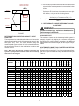
1
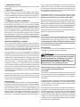
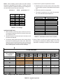
2010-2011 Goodman Manufacturing Company, L.P.
SPLIT SYSTEM OUTDOOR UNIT © 5151
San Felipe, Suite 500, Houston, TX 77056
CKL , CKF, CPKF SERIES
INSTALLATION & OPERATING INSTRUCTIONS
IMPORTANT SAFETY INSTRUCTIONS
The following symbols and labels are used throughout this
manual to indicate immediate or potential safety hazards. It
is the owner’s and installer’s responsibility to read and comply with all safety information and instructions accompanying
these symbols. Failure to heed safety information increases
the risk of personal injury, property damage, and/or product
damage.
Prior to installation, thoroughly familiarize yourself with this
installation manual. Observe all safety warnings. During installation or repair, caution is to be observed. It is the responsibility of the installing personnel to install the product
safely and to educate the customer on its safe use.
HIGH VOLTAGE!
Disconnect ALL power before servicing.
Multiple power sources may be present.
Failure to do so may cause property damage,
personal injury or death.
Installation and repair of this unit should be performed
ONLY by individuals meeting the requirements of an
“entry level technician” as specified by National Codes.
Attempting to install or repair this unit without such
background may result in product damage, personal
injury or death.
Do not connect to or use any device that is not designcertified by Goodman for use with this unit. Serious
property damage, personal injury, reduced unit
performance and/or hazardous conditions may result
from the use of such non-approved devices.
Shipping Inspection
Always keep the unit upright; laying the unit on its side or top
may cause equipment damage. Shipping damage, and subsequent investigation is the responsibility of the carrier. Verify
the model number, specifications, electrical characteristics,
and accessories are correct prior to installation. The distributor or manufacturer will not accept claims from dealers for
transportation damage or installation of incorrectly shipped
units.
Codes & Regulations
This product is designed and manufactured to comply with
national codes. Installation in accordance with such codes
and/or prevailing local codes/regulations is the responsibility
of the installer. The manufacturer assumes no responsibility
for equipment installed in violation of any codes or regulations.
www.goodmanmfg.com -or- www.amana-hac.com
P/N: IO-382C Date: September 2011
Handling of refrigerant may be governed by various regulations regarding the introduction and disposal of refrigerants. Failure to follow these regulations may harm the
environment and can lead to the imposition of substantial fines. Should you have any questions please contact the
local office of the regulatory agency in your countries.
Replacement Parts
When reporting shortages or damages, or ordering repair
parts, give the complete product model and serial numbers
as stamped on the product. Replacement parts for this product are available through your contractor or local distributor.
For the location of your nearest distributor consult the white
business pages, the yellow page section of the local telephone book or contact:
CONSUMER AFFAIRS
GOODMAN MANUFACTURING COMPANY, L.P.
7401 SECURITY WAY
HOUSTON, TEXAS 77040
877-254-4729
NOTE: Information contained in this manual pertains only
to equipment intended for outdoor installation. For additional information refer to literature packaged with other
system components.
Pre-Installation Instructions
Carefully read all instructions for the installation prior to installing product. Make sure each step or procedure is understood and any special considerations are taken into account
before starting installation. Assemble all tools, hardware and
supplies needed to complete the installation. Some items may
need to be purchased locally. Make sure everything needed
to install the product is on hand before starting.
INSTALLATION AND OPERATING INFORMATION
FOR UNITS WITH SCROLL COMPRESSORS
CAUTION
Use care when handling scroll compressors. Dome temperatures could be hot.
The following information should be read prior to installing
units with scroll compressors.
1. PUMP DOWN PROCEDURE
CAUTION
2. CRANKCASE HEATER
Scroll equipped units do not have and do not require a crankcase heater.
3. TIME DELAY COMPONENT
The time delay is located in the low voltage control circuit.
When the compressor shuts off due to thermostat operation
or a power failure, this components keeps the compressor off
for at least 30 seconds which allows the system pressure to
equalize.
4. UNBRAZING SYSTEM COMPONENTS
If the refrigerant charge is removed from a scroll equipped
unit by bleeding the high side only, it is sometimes possible
for the scrolls to seal, preventing pressure equalization through
the compressor. This may leave the low side shell and suction line tubing pressurized. If a brazing torch is then applied
to the low side while the low side shell and suction line contains pressure, the pressurized refrigerant and oil mixture
could ignite when it escapes and contacts the brazing flame.
To prevent this occurrence , it is important to check both the
high and low side with manifold gauge before unbrazing, bleed
refrigerant from both the high and low side.
such a manner that the discharge of the mower will be directed away from the unit. There must be air filters installed
in the system at some point upstream to the indoor coil. Air
filters should be inspected and, if necessary, replaced and/
or cleaned AT LEAST once a month.
If disposable filters are used, an adequate supply of clean,
unused filters of the correct size should be kept available.
Equipment should never be operated without filters.
Permanent type filters may be vacuumed and/or washed but
should not be reinstalled until thoroughly dry. Most air filters
are marked to indicate the direction of air flow, and this should
be carefully noted when they are being installed. Never turn
a dirty filter to allow air flow in the opposite direction.
The blower and motor bearings are permanently lubricated
and do not require additional lubrication.
EQUIPMENT
Some outdoor units have corresponding heaters that are
factory wired in such a manner that they are in operation
whenever the main power supply to the unit is on. Before
starting equipment after prolonged shutdowns or at the
time of initial start up, be sure that the circuits to the units
are closed for at least 24 hours.
IMPORTANT MESSAGE TO OWNER:
These instructions should be carefully read and kept for
future reference. It is suggested that this booklet be saved for
future references. It is addressed to your dealer and serviceman, but we highly recommend you read it, paying particular
attention to the section titled MAINTENANCE.
APPLICATION
It is not the intent of the manufacturer that this equipment be
used with components other than indicated.
The manufacturer assumes no responsibility for equipment
installed in violation of any code or regulation. The manual will
instruct you in the service and care of your unit. Have your
installer go over the manual with you so that you fully understand your air conditioner and how it is intended to function.
Do not connect to or use any device that is not designcertified by Goodman for use with this unit. Serious
property damage, personal injury, reduced unit
performance and/or hazardous conditions may result
from the use of such non-approved devices.
The heat pump is a relatively simple device. It operates
exactly as a summer air conditioning unit on the cooling
cycle. Always let the thermostat control system operation. Do
Not try to second guess the thermostat or tamper with it. If the
conditioned area temperature is not suitable, change the
thermostat setting one degree at a time until desired comfort
level is achieved.
Reference Specification Sheets For Performance Values And Approved System Matches.
LOCATION
The outdoor unit should be located so that air flow through
the coil is unrestricted. To provide adequate service access,
do not locate service side closer than 30.5 cm to any wall or
obstruction.
A heat pump in the heating mode cannot heat a building as
rapidly as a furnace heats it. It may take a day or two to “pull
down” a cold, moist house when the unit is initially installed
or after prolonged shutdowns.
Consider the affect of outdoor fan noise on conditioned space
and any adjacent occupied space. It is recommended that the
unit be placed so that discharge does not blow toward
windows less than 7.6 m away.
MAINTENANCE
It is recommended that the outdoor unit be inspected and, if
necessary, cleaned each cooling season. Particular attention
should be given to the air inlet side of the outdoor coil to insure that leaves, grass, etc., are not being drawn into the
unit. Restriction to air flow across the coil will result in loss of
system capacity, high operating pressures and excessive
operating costs. If the outdoor unit is installed adjacent to a
grassy area, it is suggested that lawn mowers be routed in
The outdoor unit should be set on a solid, level foundation preferably a concrete slab at least 10.2 cm thick. The slab
should be above ground level and surrounded by a graveled
area for good drainage. Any slab used as a unit foundation
should not adjoin the building as it is possible that sound and
vibration may be transmitted to the structure. For rooftop
installation, steel or treated wood beams should be used as
unit support for load distribution.
2
This equipment has been started at minimum rated voltage
and checked for satisfactory operation. Do not attempt to
operate this unit if available voltage is not within the minimum
and maximum shown on nameplate.
Heat pumps require special location consideration in areas
of heavy snow accumulation and/or areas with prolonged
continuous subfreezing temperatures. Heat pump unit bases
are cutout under the outdoor coil to permit drainage of frost
accumulation. Units must be situated to permit free unobstructed drainage of the defrost water and ice. A minimum
7.6 cm clearance under the outdoor coil is required in the
milder climates.
NOTE: Units are shipped without refrigerant and are
pressurized with a nitrogen holding charge of 125 PSI.
This charge must be removed and unit evacuated and
charged as per the installation instructions. Release holding
charge by opening the suction valve first then the liquid line
valve before attaching and brazing lines. When opening
valves with retainers, open each valve only until the top of the
stem is 1/8" from the retainer. To avoid loss of refrigerant, DO
NOT apply pressure to the retainer. When opening valves
without a retainer remove service valve cap and insert a hex
wrench into the valve stem and back out the stem by turning
the hex wrench counterclockwise. Open the valve until it
contacts the rolled lip of the valve body.
NOTE: These are not back-seating valves. It is not necessary
to force the stem tightly against the rolled lip.
In more severe weather locations, it is recommended that
units be elevated to allow unobstructed drainage and air flow.
While there are no hard and fast rules regarding elevation, we
suggest the following minimums:
If the outdoor unit is mounted above the air handler, the
maximum lift should not exceed 21.3 m (suction line). If air
handler is mounted above condensing unit, the lift should not
exceed 15.2 m (liquid line).
Insulation of at least 1.3 cm wall thickness should be used on
the suction line to prevent condensation when cooling and
heat loss when heating. The insulation should be installed on
the tubing prior to installation and should be run the entire
length of the installed line. The end of the tubing over which
the insulation is being slipped should be covered to insure
that no foreign material is introduced to the interior of the
tubing. The outdoor units are equipped with two service
valves, and, “as shipped”, the valves are in the front-seated
or “closed” position.
The indoor coil is pressurized; the copper cap must be
punctured to permit a gradual escape of the pressure prior to
un-sweating those caps. Immediately couple the tubing to
the indoor unit to minimize exposing the coils to moisture.
-
REFRIGERANT LINE CONNECTIONS
IMPORTANT
To avoid overheating the service valves or expansion device
while brazing, wrap the component with a wet rag, or use a
thermal heat trap compound. Be sure to follow the
manufacturer’s instruction when using the heat trap compound.
NOTE: Remove Schrader valves from service valves before
brazing tubes to the valves. Use a brazing alloy of 2%
minimum silver content. Do not use flux. Torch heat required
to braze tubes of various sizes is proportional to the size of
the tube. Tubes of smaller size require less heat to bring the
tube to brazing temperature before adding brazing alloy.
Applying too much heat to any tube can melt the tube. Service
personnel must use the appropriate heat level for the size of
the tube being brazed.
NOTE: The use of a heat shield when brazing is recommended to avoid burning the serial plate or the finish of the
unit.
INSTALLATION, ELECTRICAL
The supply power, voltage, frequency and phase must coincide
with that on unit nameplate. All wiring should be carefully
checked against the manufacturer’s diagrams. Field wiring
must be connected in accordance with the National Electric
Code or other local codes that may apply. Make certain that
the equipment is adequately grounded per local code requirements.
The manufacturer bears no responsibility for damage caused
to equipment or property as a result of the use of larger than
recommended size protective devices as listed on the unit
rating plate.
3
NOTE: Be careful not to kink or dent refrigerant lines. Kinked
or dented lines will cause poor performance or compressor
damage. Do NOT make final refrigerant line connection until
plugs are removed from refrigerant tubing.
2. Evacuate the system to 250 microns or less using suction
and liquid service valves. Using both valves is necessary
as some compressors create a mechanical seal separating the sides of the system.
3. Close pump valve and hold vacuum for 10 minutes.
Typically pressure will rise during this period.
•
If the pressure rises to 1000 microns or less and
remains steady the system is considered leak-free;
proceed to startup.
1. The ends of the refrigerant lines must be cut square,
deburred, cleaned, and be round and free from nicks or
dents. Any other condition increases the chance of a
refrigerant leak.
2. “Sweep” the refrigerant line with nitrogen or inert gas
during brazing to prevent the formation of copper-oxide
inside the refrigerant lines. A blockage or failure of the
metering device could result if copper-oxide is flushed
into the metering device.
3. After brazing, quench the joints with water or a wet cloth
to prevent overheating of the service valve.
REFRIGERANT LINE LENGTH (METERS)
0-7.5
Suct
15.9
19.1
19.1
19.1
19.1
22.2
22.2
7.6-15.1
15.2-22.6
Line Diameter OD (mm)
Liq
Suct
Liq
Suct
Liq
6.4
19.1
9.5
19.1
9.5
9.5
19.1
9.5
19.1
9.5
9.5
*19.1
9.5
22.2
12.7
9.5
22.2
9.5
22.2
12.7
9.5
22.2
9.5
28.6
12.7
9.5
28.6
9.5
28.6
12.7
9.5
28.6
9.5
28.6
12.7
• If pressure rises above 1000 microns but holds steady
below 2000 microns, moisture and/or non-condensibles
may be present or the system may have a small leak.
Return to step 2: If the same result is encountered check
for leaks as previously indicated and repair as necessary
then repeat evacuation.
• If pressure rises above 2000 microns, a leak is present.
Check for leaks as previously indicated and repair as
necessary.
• If pressure rises above 2000 microns, a leak is present.
Check for leaks as previously indicated and repair as
necessary then repeat evacuation.
> >
Cond
Unit
Tons
1 1/2
2
2 1/2
3
3 1/2
4
5
* - 19.1 mm REQUIRED FOR FULL RATINGS
^ - 22.2 mm REQUIRED FOR FULL RATINGS
4. Ensure the filter drier paint finish is intact after brazing. If
the paint of the steel filter drier has been burned or
chipped, repaint or treat with a rust preventative. This is
especially important on suction line filter driers which
are continually wet when the unit is operating.
System Start Up
When opening valves with retainers, open each valve only
until the top of the stem is 1/8" from the retainer. To avoid loss
of refrigerant, DO NOT apply pressure to the retainer. When
opening valves without a retainer remove service valve cap
and insert a hex wrench into the valve stem and back out the
stem by turning the hex wrench counterclockwise. Open the
valve until it contacts the rolled lip of the valve body. NOTE:
These are not back-seating valves. It is not necessary to
force the stem tightly against the rolled lip. Open the suction
service valve first! If the liquid service valve is opened first, oil
from the compressor may be drawn into the indoor coil TXV,
restricting refrigerant flow and affecting operation of the
system. After the refrigerant charge has bled into the system,
open the liquid service valve. The service valve cap is the
secondary seal for the valves and must be properly tightened
to prevent leaks. Make sure cap is clean and apply refrigerant
oil to threads and sealing surface on inside of cap. Tighten
cap finger-tight and then tighten additional 1/6 of a turn (1
wrench flat), or to the following specification, to properly seat
the sealing surfaces.
NOTE: Before brazing, verify indoor piston size by checking
the piston kit chart packaged with indoor unit.
Leak Testing (Nitrogen or Nitrogen-Traced)
Pressure test the system to approximately 100 PSI with dry
nitrogen and use soapy water to locate leaks. If you wish to
use a leak detector, charge the system to 10 psi using the
appropriate refrigerant then use nitrogen to finish charging
the system to working pressure then apply the detector to
suspect areas. If leaks are found, repair them. After repair,
repeat the pressure test. If no leaks exist, proceed to system
evacuation.
System Evacuation
NOTE: Scroll compressors should never be used to evacuate or pump down a heat pump or air conditioning system.
1. Connect the vacuum pump with 250 micron capability to
the service valves.
4
1. 3/8" valve to 5 - 10 in-lbs (0.56-1.30 Nm)
2. 5/8" valve to 5 - 20 in-lbs (0.56-2.26 Nm)
3. 3/4" valve to 5 - 20 in-lbs (0.56-2.26 Nm)
4. 7/8" valve to 5 - 20 in-lbs (0.56-2.26 Nm)
Airflow Determination - Indoor Coil
The heat pump system has been designed for optimum performance with the airflow across the indoor coil equaling
approximately 190 L/s per TON.
e.g.
A 2 TON system should have 2 x 190 = 380 L/s.
Do not introduce liquid refrigerant from the cylinder into the
crankcase of the compressor as this may damage the compressor.
Temperature Rise Method - Although not as accurate as the
use of test equipment, a method of determining the indoor
airflow in a system employing electric resistance heat as the
backup heat source is by the temperature rise method and is
calculated using the following formula:
1. Purge gauge lines after attaching to the service valves.
2. Determine the proper charge from the serial data plate.
Charge includes the evaporator coil and 7.6 m of line set.
Systems having more than 7.6 m of interconnecting tubing
require an additional charge allowance of 6 oz.
3. Break the vacuum by opening the suction and liquid
valves on the gauge set and weighing in the calculated
charge.
4. Set thermostat to call for cooling. Check indoor and
outdoor fan operation and allow system to stabilize for 10
minutes for fixed orifices.
828.3 x Input Power (kW)
Air Flow (L/s) =
Temperature Rise (°C)
where
measured input voltage (Volt) x current (Amp)
kW =
1000
e.g.
input voltage = 230 Volt, measured current 35 amps
temperature rise = 12°C
FINAL CHARGE ADJUSTMENT
The outdoor temperature must be 60°F (16°C) or higher.
Set the room thermostat to COOL, fan switch to AUTO,
and set the temperature control well below room temperature. After system has stabilized per startup instructions,
check superheat as detailed in the following section.
air flow = 828.3 * 230 * 35 / 1000 / 12
= 556 (L/s)
NOTE: The compressor circuit (outdoor unit) must be off
to insure that the Temperature Rise measured across
the indoor unit is due only to the electric heat.
GENERAL:
The following information has been developed to assist the
service technician in determining the proper charge for
Goodman® Heat Pump Systems.
The following procedure should be followed in determining
the temperature rise across the indoor section:
It must be noted that many field variations exist that may
effect the operating temperature and pressure readings of a
heat pump system.
It should also be noted that all Goodman® Heat Pump
Systems utilize fixed orifice refrigerant control devices. As such,
the following procedures have been developed for this type of
refrigerant control device.
1. Use the same thermometer for the measuring the return
and supply air temperatures to avoid thermometer error.
2. Measure the temperatures within 1.8 meters of the indoor
section and downstream from any mixed air source making sure that the thermometer is not exposed to any
radiant heat areas.
I. DETERMINATION OF INDOOR AIR FLOW (L/S) AND
HEATING CAPACITY (KW)
3. Make sure that the air temperature is stable before making
measurement.
Prior to using the methods described below to check the
system’s charge it is important to verify that the system is
delivering sufficient air across the indoor coil (L/s, liters per
second), as well as, the operating capacity of the system. The
following procedures are suggested methods for determining the system air flow (L/s) and its operating capacity (kW).
Airflow Test Instruments - There are a number of readily
available instruments which can be used in the field for airflow
determination such as Barometers, Volume-Aire Air Balancers, Anemometers, and Velometers. When using these devices it is important to follow the manufacture’s instructions
provided with them.
5
1. Use the same procedure described above to determine
system Airflow and temperature rise across the indoor
section.
DO NOT MEASURE IN
RADIANT HEAT AREA
SUPPLY
2. Referring to Table I, determine the power output of the
system for the measured Temperature Rise and system air flow, or by use of the following formula:
HEATER
MEASURE
Airflow (L/s) x Temperature Rise (°C)
ΔΤ
Power (kW) =
828.3
AIRHANDLER
II. REFRIGERANT CHARGE DETERMINATION AND
ADJUSTMENT
RETURN
WARNING
To avoid possible injury, explosion or death, practice
safe handling of refrigerants.
FIGURE
COOLING CYCLE:
The method to insure that the heat pump/cooling system is
properly charged is by weighing in the amount of refrigerant
specified on the outdoor sections nameplate, with additional
adjustments for line size, line length, and other system components.
DETERMINATION OF HEATING CAPACITY - HEAT
PUMP ONLY
The temperature rise method described above can be used to
determine the heating capacity of the heat pump system in the
heat pump “only” mode. The results obtained using this
method should agree to within 10% of the data published in
the specification sheets for the combination of indoor and
outdoor section.
SYSTEMS WITH MORE THAN 7.6 METERS OF REFRIGERANT LINE REFRIGERANT Allowance
Systems having more than 7.6 m of interconnecting refrigerant lines require an additional charge allowance of R22 per
Table II.
Note - When using the following procedure to determine the
system’s capacity make sure that the indoor sections backup
heat source is de-energized.
HEAT
OUTPUT
KW
3
4
5
6
7
8
9
10
11
12
13
14
15
16
17
18
19
20
2
0
0
2
5
0
3
0
0
3
5
0
4
0
0
12.4
16.6
20.7
24.8
29.0
33.1
37.3
41.4
45.6
49.7
9.9
13.3
16.6
19.9
23.2
26.5
29.8
33.1
36.4
39.8
43.1
46.4
49.7
8.3
11.0
13.8
16.6
19.3
22.1
24.8
27.6
30.4
33.1
35.9
38.7
41.4
44.2
46.9
49.7
7.1
9.5
11.8
14.2
16.6
18.9
21.3
23.7
26.0
28.4
30.8
33.1
35.5
37.9
40.2
42.6
45.0
47.3
6.2
8.3
10.4
12.4
14.5
16.6
18.6
20.7
22.8
24.8
26.9
29.0
31.1
33.1
35.2
37.3
39.3
41.4
AIRFLOW – Liters per second (L/s)
4
5
5
6
6
7
7
8
8
5
0
5
0
5
0
5
0
5
0
0
0
0
0
0
0
0
0
9
0
0
9
5
0
1
0
0
0
1
0
5
0
1
1
0
0
1
1
5
0
1
2
0
0
1
2
5
0
7.4
8.3
9.2
10.1
11.0
12.0
12.9
13.8
14.7
15.6
16.6
17.5
18.4
7.8
8.7
9.6
10.5
11.3
12.2
13.1
14.0
14.8
15.7
16.6
17.4
7.5
8.3
9.1
9.9
10.8
11.6
12.4
13.3
14.1
14.9
15.7
16.6
7.9
8.7
9.5
10.3
11.0
11.8
12.6
13.4
14.2
15.0
15.8
7.5
8.3
9.0
9.8
10.5
11.3
12.0
12.8
13.6
14.3
15.1
7.9
8.6
9.4
10.1
10.8
11.5
12.2
13.0
13.7
14.4
7.6
8.3
9.0
9.7
10.4
11.0
11.7
12.4
13.1
13.8
8.0
8.6
9.3
9.9
10.6
11.3
11.9
12.6
13.3
TEMPERATURE RISE (°C)
7.4
9.2
11.0
12.9
14.7
16.6
18.4
20.2
22.1
23.9
25.8
27.6
29.5
31.3
33.1
35.0
36.8
6.6
8.3
9.9
11.6
13.3
14.9
16.6
18.2
19.9
21.5
23.2
24.8
26.5
28.2
29.8
31.5
33.1
7.5
9.0
10.5
12.0
13.6
15.1
16.6
18.1
19.6
21.1
22.6
24.1
25.6
27.1
28.6
30.1
6.9
8.3
9.7
11.0
12.4
13.8
15.2
16.6
17.9
19.3
20.7
22.1
23.5
24.8
26.2
27.6
7.6
8.9
10.2
11.5
12.7
14.0
15.3
16.6
17.8
19.1
20.4
21.7
22.9
24.2
25.5
6
7.1
8.3
9.5
10.6
11.8
13.0
14.2
15.4
16.6
17.7
18.9
20.1
21.3
22.5
23.7
7.7
8.8
9.9
11.0
12.1
13.3
14.4
15.5
16.6
17.7
18.8
19.9
21.0
22.1
7.2
8.3
9.3
10.4
11.4
12.4
13.5
14.5
15.5
16.6
17.6
18.6
19.7
20.7
7.8
8.8
9.7
10.7
11.7
12.7
13.6
14.6
15.6
16.6
17.5
18.5
19.5
4. Determine the systems superheat as follows:
NOTE - When installing systems were the indoor outdoor
sections are separated by more than 7.6 meters, note the
maximum elevation separation limitations per the diagram in
the LOCATION section of these instructions.
Allowance
LINE
O. D. (mm)
6.4
9.5
12.7
15.9
19.1
22.2
28.6
34.9
(R-22)
LIQUID
LINE
20.5
54.0
106.0
173.0
a. Read the system’s suction pressure, then using Table
III determine the system’s saturated suction tempera
ture.
gram/meter 20.5
b. Read the suction line temperature.
c. The system’s superheat = the suction line tempera
ture - the saturated liquid temperature.
SUCTION
LINE
SUCTION
PRESSURE KPa
345
365
380
400
420
435
455
475
495
515
540
560
3.8
5.6
7.4
14.0
20.5
TABLE II - Line Charge
SUPERHEAT METHOD :
1. With both base valves fully open, connect a set of service gauges to the base valves’ service port, being careful to purge the lines.
SATURATED SUCTION
TEMPERATURE °C
-3.3
-2.2
-1.1
0
1.1
2.2
3.3
4.4
5.6
6.7
7.8
8.9
2. Allow the system to operate at least 10 minutes or until
the pressures stabilize.
TABLE III - Saturated Suction Pressure (R-22)
3. Temporarily install a thermometer on the suction (large)
line near the condensing unit’s base valve. Make sure
that there is good contact between the thermometer and
the refrigerant line and wrap the thermometer and line
with insulating tape to assure accurate readings.
5. Refer to Table IV for the proper system superheat. Adjust
the charge as necessary by adding charge to lower the
superheat or bleeding the charge to raise the superheat.
SYSTEM SUPERHEAT
Ambient Condenser
Inlet Temperature
( °C Drybulb )
Return Air Temperature ( 50%RH )
Drybulb Wetbulb Drybulb Wetbulb Drybulb Wetbulb Drybulb Wetbulb Drybulb Wetbulb
18º
12º
21º
14º
24º
17º
27º
19º
29º
22º
46
---
---
---
---
3
38
---
---
---
3
3
35
---
---
3
3
32
---
---
3
6
6
29
---
3
3
7
9
27
3
3
3
10
11
24
3
3
6
11
12
21
3
3
8
13
14
18
3
6
11
14
16
16
4
8
12
16
17
NOTE: * Charge 3° super heat, all other could be ± 1.1°C
TABLE IV - System Superheat
7
*
5
6. Remove the service gauge set’s lines carefully - Escaping liquid refrigerant can cause burns.
12. If unit operates properly on the heating cycle, raise the
heating temperature setting high enough until the heating second-stage mercury bulb (lower) makes contact.
CAUTION
13. Supplementary resistance heat, if installed, should now
come on. Make sure it is operating correctly. If outdoor
thermostats are installed, the outdoor ambient must be
below the set point of these thermostats for heaters to
operate. It may be necessary to jumper these thermostats to check heater operation if outdoor ambient is mild.
To prevent personal injury, carefully connect and disconnect
manifold gauge hoses. Escaping liquid refrigerant can cause
burns. Do not vent refrigerant into the atmosphere. Recover
all refrigerant during system repair and before final unit
disposal.
14. For thermostats with emergency heat switch, return to
startup (item #9). The emergency heat switch is located
at the bottom of the thermostat. Move this switch to emergency heat. The heat pump will stop, the indoor blower
will continue to run, all heaters will come on and the thermostat emergency heat light will come on.
HEAT PUMP HEATING CYCLE
Weighing In Charge
As in the cooling mode the proper method of insuring that the
system is properly charged is by weight with the additional
charge adjustments for line size, line length, and other system
components as previously indicated.
STARTUP PROCEDURE AND CHECK LIST
Begin with power turned off at all disconnects.
15. If checking the unit on the heating cycle in the wintertime, when the outdoor coil is cold enough to actuate the
defrost control, observe at least one defrost cycle to make
sure the unit defrosts properly.
1. Set first-stage thermostat heat anticipator to .12 (amps)
and turn thermostat system switch to “Cool” and fan switch
to “Auto”.
16. Check to see if all supply and return air grilles are adjusted and air distribution system is balanced for the best
compromise between heating and cooling.
2. Turn cooling temperature setting as high as it will go.
17. Check for air leaks in the ductwork.
3. Inspect all registers and set them to the normal open position.
18. Make sure the heat pump is free of “rattles”, and the tubing in the unit is free from excessive vibration. Also make
sure lines are not rubbing against each other or sheet
metal surfaces or edges. If so, correct the trouble.
4. Turn on the unit electrical supply at the fused disconnect
switch, both for the indoor unit and the outdoor unit.
19. Set thermostat at the appropriate setting for cooling and
heating or automatic changeover for normal use.
5. Turn the fan switch to the “On” position. The blower should
operate 10 to 15 seconds later.
20. Be sure the owner is instructed on the unit operation,
filter servicing, correct thermostat operation, etc.
6. Turn the fan switch to the “Auto” position. The blower
should stop 90 seconds later.
The foregoing “Start-up Procedure and Check List” is recommended to serve as an indication that the heat pump system
will operate normally.
Note: If outdoor temperature is below 12.8°C, proceed to
step 9. Do not check out in the cooling mode.
7. Slowly lower the cooling temperature until the first mercury bulb makes contact. The compressor, indoor blower,
and outdoor fan should now be running. Make sure cool
air is supplied by the unit.
COMPONENTS:
1. Contactor - This control is activated (closed) by the room
t-stat for both heating and cooling. It is de-energized (open)
during emergency heat. The contactor has a 24 volt coil
and supplies power to the compressor and outdoor fan
motor.
8. Turn system switch to “Heat” and fan switch to “Auto”.
9. Slowly raise the heating temperature setting. After the heating first-stage mercury bulb (upper) makes contact, stop
moving the lever. The compressor, indoor blower and outdoor fan should now be running. After giving the unit time
to settle out, make sure heated air is being supplied by
the indoor unit.
2. Crankcase Heater - This item is on whenever power is
supplied to the outdoor unit. It warms the compressor
crankcase, thereby preventing liquid migration and subsequent compressor damage. It is connected electrically
to the contactor L1 and L2 terminals.
10. If the outdoor ambient is above 21.1°C, the compressor
may trip on internal overload.
3. Condenser motor - The condenser motor is activated by
the contactor during heating and cooling except during
defrost and emergency heat operation.
11. In the event that the outdoor ambient is too high to allow
a thorough heating cycle check, postpone the test until
another day when conditions are more suitable...but —
DO NOT FAIL TO TEST.
4. Compressor - This item is activated by the contactor for
heating and cooling except during emergency heat. It is
protected by an internal overload.
8
G. When the defrost thermostat has closed, short the “test”
pins on the board until the reversing valve shifts, indicating defrost. This could take up to 21 seconds depending on what timing period the board is set on. After
defrost initiation, the short must instantly be removed or
the defrost period will only last 2.3 seconds.
5. Defrost Control - The defrost control provides time/ temperature initiation and termination of the defrost cycle.
6. Loss Of Charge Protector - The control opens from its
normally closed position to open the compressor contactor
should the system lose its refrigerant charge.
7. Outdoor Thermostats - These optional controls are used
to prevent full electric heater operation at varying outdoor
ambient (-17.8 to 7.2°C). They are normally open above
their set points and closed below to permit staging of indoor supplemental heater operation.
H. After the defrost has terminated, check the defrost thermostat for 24 volts between “DFT” and “C”. The reading
should indicate 0 volts (open sensor).
I.
Shut off power to unit.
J. Replace outdoor fan motor lead and turn on power.
8. Reversing Valve Coil - This coil is activated by the thermostat (system switch) during cooling only and during
defrost. It positions the reversing valve pilot valve for cooling operation.
OPERATION - GENERAL
EXPLANATION AND GUIDANCE
The heat pump is a relatively simple device. It operates exactly
as a Summer Air Conditioning unit when it is on the cooling
cycle. Therefore, all the charts and data for service that apply to
summer air conditioning apply to the heat pump when it is on
the cooling cycle, and most apply on the heating cycle except
that “condenser” becomes “evaporator”, “evaporator” becomes
“condenser” and “cooling” becomes “heating”.
OPERATION:
In operation the power to the circuit board is controlled by a
temperature sensor which is clamped to a return bend on the
outdoor coil. Timing periods of 30, 60, or 90 minutes may be
selected by connecting the circuit board jumper wire to 30,
60, 90 respectively.
Accumulation of time for the timing period selected starts
when the sensor closes (approximately -2.2°C) and when the
wall thermostat is calling for heat. At the end of the timing period,
a defrost cycle will be initiated provided the sensor remains
closed.
When the heat pump is on the heating cycle, it is necessary
to redirect the refrigerant flow through the refrigerant circuit
external to the compressor. This is accomplished with a
reversing valve. Thus, the hot discharge vapor from the
compressor is directed to the inside coil (evaporator on the
cooling cycle) where the heat is removed, and the vapor
condenses into liquid. It then goes through a capillary tube, or
expansion valve, to the outside coil (condenser on the cooling
cycle) where the liquid is evaporated, and vapor goes to the
compressor.
When the sensor opens (approximately 18.3°C), the defrost
cycle is terminated. If the defrost cycle is not terminated due to
the sensor temperature, a 10 minute override interrupts the
defrost period.
When the solenoid valve is operated either from heating to
cooling or vice versa, it moves the pilot valve, thus putting
suction pressure (low pressure) on one side of the piston of
the reversing valve, and since discharge pressure (high pressure) is on the other side of the piston, the piston slides to the
low pressure side and reverses the flow of the refrigerant in
the circuit.
SUGGESTED FIELD TESTING / TROUBLE SHOOTING
A. Run unit in heat mode.
B. Check unit for proper charge. Note: Bands of frost indicate low refrigerant charge
C. Shut off power to unit.
D. Disconnect outdoor fan by removing the purple lead from
“DF2” on defrost control.
E. Restart unit and allow frost to accumulate.
F. After a few minutes of operation, the defrost thermostat
should close. To verify this, check for 24 volts between
“DFT” and “C” on board. If the temperature at the thermostat is less than -2.2°C and the thermostat is open,
replace the thermostat as it is defective.
9
When the heat pump is on the heating cycle, at which time
the outdoor coil is functioning as an evaporator, the temperature of the refrigerant in the outdoor coil must be below the
temperature of the outdoor air in order for the refrigerant in
the outdoor coil to extract heat from the air. Thus, the greater
the difference in outdoor temperature and outdoor coil
temperature, the greater the heating capacity of the heat
pump. Since this is characteristic of heat pumps, it is good
practice to provide supplementary heat for all heat pump
installations in areas where the temperature drops below
7.2°C. It is also good practice to provide sufficient supplementary heat to handle the entire heating requirements if
there should be a failure of heat pump, such as a compressor
failure, or refrigerant leak, etc.
The following figures show a schematic of a heat pump on
the cooling cycle and the heating cycle
Heat Pump Refrigerant Circuit
Since the temperature of the liquid refrigerant in the outdoor coil
on the heating cycle is generally below the freezing point, frost
forms on the surfaces of the outdoor coil under certain
weather conditions of temperature and relative humidity,
Therefore, it is necessary to reverse the flow of the refrigerant to provide hot gas in the outdoor coil to melt the frost
accumulation. This is accomplished by reversing the heat
pump to the cooling cycle. At the same time, the outdoor fan
stops to hasten the temperature rise of the outdoor coil and
lessen the time required for defrosting. The indoor blower
continues to run and the supplementary heaters are energized.
SERVICE:
The following information is for use by qualified service
agency only; others should service this equipment.
Common Causes of Unsatisfactory Operation of Heat
Pumps on the Heating Cycle.
A. Dirty Filters or inadequate air volume through indoor coil.
When the heat pump is on the heating cycle, the indoor
coil is functioning as a condenser; therefore, the filters
must always be clean, and sufficient air volume must
pass through the indoor coil to prevent excessive discharge pressure and high pressure cut-out.
nI
B. Outside Air into Return Duct: Cold outside air should
not be introduced in the return duct of a heat pump installation on the heating cycle close enough to the indoor coil to reduce temperature of the air entering the
coil below 18.3°C. Air below this temperature will cause
low discharge pressure, thus low suction pressure and
excessive defrost cycling with resultant low heating output. It may also cause false defrosting.
In addition to a reversing valve, a heat pump is equipped with
an expansion device and check valve for the inside coil, and
similar equipment for the outside coil. It is also provided with
a defrost control system.
C. Undercharge: Undercharge on the heating cycle will
cause low discharge pressure resulting in low suction
pressure and frost accumulation on the lower part of
the outdoor coil.
The expansion device performs the same function on the
heating cycle as on the cooling cycle. The check valves are
required due to the reverse flow of refrigerant when changing from cooling to heating or vice versa.
10
D. Poor “Terminating” Defrost Thermostat contact. Defrost
thermostat must make good thermal contact on return
bend, otherwise it may not terminate the defrost cycle
quickly enough to prevent unit from cutting out on high
discharge pressure during the defrost cycle.
When the outdoor temperature drops to a point where the
heat pump alone cannot supply enough heat for your home,
electric heaters are automatically brought on to supply the
needed additional heat. At this time, your unit will operate
continuously. This is normal. During a severe cold spell, your
heat pump may run continuously for several days.
To realize the economical operational benefits of your heat
pump, the amount of time the electric heaters are in operation should be kept to a minimum. These heaters are controlled by the thermostat and come on at about two degrees
below thermostat setting. Therefore, each time the thermostat setting is moved up two degrees, the heaters are
energized in addition to the heat pump. For economical
operation, the thermostat should be set to the desired
temperature and left there throughout the heating season.
The practice of setting the thermostat back a few degrees at
night is not recommended as the heat pump will have to work
harder in the morning and may take a relatively long time to
warm the house to the desired level. It is also uneconomical
as the electric heaters would be energized. A heat pump is
most economical when maintaining a desired temperature.
E. Malfunctioning Reversing Valve: This may be due to:
1. Solenoid not energized. In order to determine if the solenoid is energized, touch the nut that holds the solenoid
cover in place with a screwdriver. If the nut magnetically
holds the screwdriver in cooling, the solenoid is energized.
2. No voltage to solenoid: Check voltage. If no voltage, check
wiring circuit.
3. Valve will not shift :
a. Undercharged : (A) check for leaks;
b. Valve Body Damaged: Replace valve;
c. Unit Properly Charged: If it is on the heating cycle,
raise discharge pressure by restricting air flow through
the indoor coil. If the valve does not shift, tap it lightly
on both ends with screwdriver handle. Do Not Tap The
Valve Body. If unit is on the cooling cycle, raise discharge pressure by restricting air flow through the outdoor coil. If the valve does not shift after the above attempts, cut the unit off and wait until the discharge and
suction pressure equalize, and repeat above steps. If
the valve does not shift, replace it.
Under normal operation, the air delivered from your registers may feel less warm than that supplied from a gas or
oil fired furnace. This is also normal. The heat pump
supplies larger quantities of air at a lower temperature.
This results in more uniform room temperature since the
heated air is closer to room temperature, eliminating hot
areas near the registers. The heated air will generally
range in the area of 32.3° to 37.8°C, more than ample to
heat your home.
It is important that large quantities of this air be delivered.
Restricted air flow will result in high operating cost, poor
heating and possible equipment malfunctions or damage.
Closed registers and dirty filters are the primary cause of
restricted air flow. All registers, supply and return, should be
open and not blocked by carpet or furniture. Filters must be
inspected at least once each month and cleaned or changed
if necessary. We hope you have found this information
helpful. We also want to remind you that your closest and best
source of information is your installing dealer. Be sure to have
your installer go over your system with you and show you filter
and fuse locations and answer any questions you may have.
We strongly recommend a yearly inspection of your unit by
a qualified service technician. Most dealers offer a maintenance or service contract which includes this service.
DEAR HOMEOWNER:
Your heat pump will provide you with years of year-round
comfort. The following paragraphs are our introduction to you
on the operation of your new heating and air conditioning
system. There are certain operational characteristics of a
heat pump with which the homeowner should become familiar.
A heat pump operates by removing heat from the outdoor air
and actually “pumping” it indoors via a refrigerant circuit.
Obviously, the colder the outdoor air becomes, the more
difficult it is for the heat pump to remove heat from it, even
though it will remove heat from even the coldest of air. As it
becomes colder outdoors, the air from your registers will
gradually become less warm. Although this air may feel less
warm, it contains enough heat to warm your home except in
the most extreme weather.
11
LONG LINE APPLICATIONS
Cond
Unit
Tons
1-1/2
2
2-1/2
3
3-1/2
4
5
0-7.3
Suct
15.9
15.9
19.1
19.1
19.1
22.2
22.2
Liq
6.4
6.4
9.5
9.5
9.5
9.5
9.5
REFRIGERANT LINE LENGTH (meters)
7.4-14.9
15.0-22.6***
22.7-30.5
Line Diameter OD (mm)
Suct
Liq
Suct
Liq
Suct
Liq
19.1
9.5
19.1
9.5
19.1
9.5
19.1
9.5
19.1
9.5
22.2
9.5
19.1*
9.5
22.2
9.5
22.2
9.5
19.1*
9.5
22.2
9.5
28.6
9.5
22.2**
9.5
28.6
9.5
28.6
9.5
28.6
9.5
28.6
9.5
28.6
9.5
28.6
9.5
28.6
9.5
28.6
9.5
30.6-38.0
Suct
19.1
22.2
22.2
28.6
28.6
28.6
34.9
Liq
9.5
9.5
9.5
9.5
9.5
9.5
9.5
38.1-45.4
Suct
22.2
22.2
28.6
28.6
28.6
28.6
34.9
* 19.1 mm required for full ratings
** 22.2 mm required for full ratings
*** for line lengths greater than 22.6 meters or vertical lifts greater than 15 meters additional engineering
considerations must be taken - contact your local distributor.
SYSTEM PERFORMANCE vs. SUCTION LINE SIZING
COND SIZE
(tons)
1-1/2
2
2-1/2
3
3-1/2
4
5
SUCT LINE
SIZE O.D.
(mm)
15.9
19.1
19.1
22.2
19.1
22.2
19.1
22.2
28.6
19.1
22.2
28.6
19.1
22.2
28.6
22.2
28.6
CAPACITY MULTIPLIERS
LENGTH OF TUBING (SUCTION LINE) - METERS
7.5
15
22.5
30
37.5
45
.98
.96
.94
.92
.90
.88
1.00
.98
.96
.94
.92
.90
1.00
.98
.96
.94
.92
.90
1.01
1.00
.99
.98
.97
.96
.99
.97
.95
.93
.91
.89
1.00
.99
.98
.97
.96
.95
.98
.96
.94
.92
.90
.88
.99
.98
.97
.96
.95
.94
1.00
.99
.98
.97
.96
.95
.97
.95
.93
.91
.89
.87
.99
.98
.97
.96
.95
.94
1.00
.99
.98
.97
.96
.95
.95
.92
.90
.86
.83
.80
.98
.96
.94
.92
.90
.88
1.00
.98
.96
.94
.92
.90
.98
.96
.94
.91
.89
.87
1.00
.98
.95
.93
.91
.89
12
Liq
9.5
9.5
9.5
9.5
9.5
9.5
9.5