1
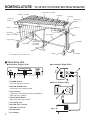
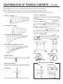
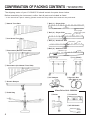
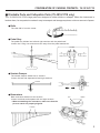
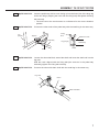
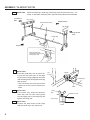
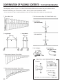
CONCERT
VIBES
YV-3910/3710/3700/2700/2700G/1600A/520
Owner’s Manual
Make sure to read the PRECAUTIONS on page 1.
SPECIAL MESSAGE SECTION
This product utilizes an external power supply (adapter). DO
NOT connect this product to any power supply or adapter
other than one described in the manual, on the name plate, or
specifically recommended by Yamaha.
WARNING: Do not place this product in a position where
anyone could walk on, trip over, or roll anything over power
or connecting cords of any kind. The use of an extension
cord is not recommended! If you must use an extension cord,
the minimum wire size for a 25" cord (or less) is 18 AWG.
NOTE: The smaller the AWG number, the larger the current
handling capacity. For longer extension cords, consult a local electrician.
Disposal Notice: Should this Product become damaged beyond repair, or for some reason its useful life is considered to
be at an end, please observe all local, state, and federal regulations that relate to the disposal of products that contain
lead, batteries, plastics, etc. If your dealer is unable to assist
you, Please contact Yamaha directly.
NAME PLATE LOCATION: The name Plate is located
on the player side of the product. The model number, serial
number, power requirements, etc., are located on this plate.
You should record the model number, serial number, and the
date of purchase in the spaces provided below and retain this
manual as a permanent record of your purchase.
This Product should be used only with the components supplied or; a cart, rack, or stand that is recommended by
Yamaha. If a cart, etc., is used, please observe all safety
markings and instructions that accompany the accessory
product.
SPECIFICATIONS SUBJECT TO CHANGE: The information contained in this manual is believed to be correct at
the time of printing. However, Yamaha reserves the right to
change or modify any of the specifications without notice or
obligation to update existing units.
NOTICE: Service charges incurred due to lack of knowledge relating to how a function or effect works (when the
unit is operating as designed) are not covered by the
manufacturer’s warranty; and are therefore the owners responsibility. Please study this manual carefully and consult
your dealer before requesting service.
ENVIRONMENTAL ISSUES: Yamaha strives to produce
products that are both user safe and environmentally
friendly. We sincerely believe that our products and the production methods used to produce them, meet these goals. In
keeping with both the letter and the spirit of the law, we want
you to be aware of the following:
NAME
PLATE
Model
Serial No.
Purchase Date
PLEASE KEEP THIS MANUAL
PRECAUTIONS
Please read the following instructions carefully before using your vibes.
● Installation Location
● When Not in Use
Use or storage in the following locations may cause
damage, even when packaged.
• In direct sunlight, such as near a window, or in a
closed vehicle in daytime.
• Near heating devices or in other locations subject
to excessive heat.
• In excessively cold environment.
• In places with excessive humidity or dust.
• Locations subject to vibrations.
The driver and the controller, in particular, must be
protected from high humidity to avoid corrosion and
short circuit.
• Make sure to turn off the power switch and disconnect the AC adapter from the outlet.
• Always engage the caster brakes.
● Do Not Use Outdoors
Avoid using the instrument outdoors. Avoid exposure
to rain or moisture.
● Maintenance
The tone bars should be polished from time to time
using a soft and dry cloth or silicone cloth. Stains that
cannot be removed with a dry cloth may be wiped off
using a small amount of ethyl alcohol. Never use
thinner or benzene or a wet cloth for cleaning purposes.
● Keep This Manual for Future Reference
After reading, make sure to keep the manual in a safe
place.
● Power Supply
Make sure to use the supplied AC adapter. Use of
different adapters may cause damage not covered by
the warranty.
Assembly Cautions
● Handling
• Never place an object on or lean against the instrument, as this may cause damage to the tone bars
and frame parts or topple the instrument, which is
extremely dangerous.
• Do not use hard orchestra bell mallets or other hard
objects on your vibes. The resulting dents or scratches
in the tone bars could impair the sound.
• Rough handling of the controller and/or the driver
may cause damage to the internal circuitry.
• Never try to disassemble the controller or driver, as
this may result in severe damage.
• When assembling/disassembling the instrument, make sure to follow the procedure outlined in this manual. Assembly in the wrong
order may impair the performance and functionality of the instrument or cause noise.
● Moving and Transporting the Instrument
• After final adjustment of the legs the fixing
screws must be tightened securely to prevent
loosening. Looseness may cause the instrument to shift during performance and can also
cause noise and other problems. Retighten
the screws from time to time.
• Move the instrument carefully to avoid shocks. Before moving the instrument, make sure that the AC
adapter is disconnected and the caster brakes are
released. Also make sure to lift the instrument slightly
when moving over rough surfaces.
• When the instrument must be transported to a different location make sure to fully disassemble it, taking
care to pack each component properly. Disassembly
steps are in the opposite order of assembly.
• Make sure to adjust the wire clip positions
after assembly. (YV-3910/3710/3700: P. 17)
• Height adjustment of the striking surface (YV3910/3710/3700: P. 18, YV-2700/2700G/
1600A/520: P 25) should be performed by AT
LEAST 2 PERSONS.
1
NOMENCLATURE
: YV-3910/3710/3700/2700/2700G/1600A/520
Accidental Tone Bars
Natural Tone Bars
Controller
Fan Belt
Frame End
(Large)
Frame End
(Small)
Slide Leg
Rail No. 1
Resonators
(Natural Tone Side)
Slant Shaft
Driver
Leg (Large)
Leg (Small)
Resonators
(Accidental
Tone Side)
Pedal Stay
Pedal
Caster
* The illustration shows model YV-3710
■ Vibes Drive Unit
● Controller (Player Side)
q POWER Switch
Turns the power on and off.
w MOTOR SPEED Slider
Controls the fan rotation speed.
e LED Indicator
Lights when the power is turned on and flashes
while the fan is rotating.
r START/STOP Button
Starts and stops fan rotation.
t DC 12V IN Jack
y MOTOR OUT Terminal
u MOTOR IN Terminal
i 8P DIN Cable
o AC Adapter
2
● Controller (Right Side)
● Driver (Player Side)
AC Adapter
CONFIRMATION OF PACKING CONTENTS
: YV-3700
The shipping carton of your YV-3700 should contain the parts shown below.
Before assembling the instrument, confirm that all parts are included as listed.
* In the event that a part is missing, please contact the shop where the instrument was purchased.
q Natural Tone Bars
i Rail (1) : Player Side
Name Plate
o Rail (2) : Player Side
Rail Clamp
Posts (Larger
number than parts
!0 and !1)
w Accidental Tone Bars
!0 Rail (3) : Audience Side
Rail Clamp
Posts
!1 Rail (4) : Audience Side
e Resonators (Natural Tone Side)
YAMAHA Logo
!2 Leg (Large)
Posts
!3 Leg (Small)
r Resonators (Accidental Tone Side)
!4 AC Adapter
t Sustain Damper
y Reinforcement Stay
!5 Synchro Belt
(Fan Belt): 2 pcs.
Vibes Drive Unit: YVM-300
!6 Driver
!7 Controller
u Pedal Stay
!8 8P DIN Cable
3
CONFIRMATION OF PACKING CONTENTS : YV-3910/3710
The shipping carton of your YV-3910/3710 should contain the parts shown below.
Before assembling the instrument, confirm that all parts are included as listed.
* In the event that a part is missing, please contact the shop where the instrument was purchased.
q Natural Tone Bars
u Rail (1) : Player Side
Name Plate
i Rail (2) : Player Side
Rail Clamp
Posts (Larger
number than parts
o and !0)
w Accidental Tone Bars
o Rail (3) : Audience Side
Rail Clamp
Posts
!0 Rail (4) : Audience Side
e Resonators (Natural Tone Side)
Posts
YAMAHA Logo
!1 Leg (Large)
!2 Leg (Small)
r Resonators (Accidental Tone Side)
!3 AC Adapter
!4 Synchro Belt
(Fan Belt): 2 pcs.
t Sustain Damper
Vibes Drive Unit: YVM-300
y Pedal Stay
!5 Driver
!6 Controller
!7 8P DIN Cable
4
CONFIRMATION OF PACKING CONTENTS : YV-3910/3710
■ Dividable Parts and Collapsible Parts (YV-3910/3710 only)
The YV-3910’s/YV-3710’s large parts are designed to either divide or collapse. When the instrument is
broken down, its compact size makes it easy to transport and storage requires a minimum amount of space.
● Rails
The rails fold in from the center.
● Pedal Stay
The pedal stay divides into left and right sections and the pedal itself.
Loosen the 2 wing nuts and remove the stays from the pedal attachment.
Loosen
● Sustain Damper
The sustain damper divides into 2 sections.
Loosen the bolt and separate left and right sections.
Loosen
● Resonators
Both resonators divide into two sections.
Loosen both bolts and separate left and right sections.
* When assembling the resonators, make sure that the
pin and notch are properly aligned.
Pin
Notch
Loosen
5
ASSEMBLY
: YV-3910/3710/3700
For safety, assembly should be performed by at least 2 persons in a location with sufficient space.
We recommend to you to assemble the instrument on a soft rug or carpet.
z Connect the large and the small leg using the reinforcement stay and pedal
stay.
* Before proceeding, make sure that the slide leg fixing bolts of the large and small leg are securely
fastened.
Leg (Small)
Leg (Large)
The tip of each slide leg fixing
bolt must be tightly seated in
one of the slide leg notches.
Slide Leg
Fixing Bolt
Slide Leg
Fixing Bolt
Slide Leg
Slide Leg
Fixing Bolt
Slide Leg
Fixing Bolt
1-1
● YV-3910/3710 : Place the large leg, small leg, pedal stay (and reinforcement stay : YV-3700)
so that after assembly each part will be positioned as illustrated.
Low Sound
Side
Leg (Large)
Slant Shaft
Audience Side
Leg (Small)
High Sound
Side
Pedal Stay
Player Side
Pedal
Align flat surfaces.
Flat surface should
face player side.
6
ASSEMBLY: YV-3910/3710/3700
1-2
● YV-3910/3710 : Insert the pedal stay with its notch facing up into the lower joint of the large leg
as far as it will go (aligning the notch with the fixing bolt) and tighten the fixing
bolt securely.
* The hole next to the notch serves as a reference for the correct insertion
position.
1-3
● YV-3910/3710 : Connect the other ends of the pedal stay with the small leg in the same way.
Leg
(Large)
Fixing
Bolt
Tighten
Reference Hole
Pedal Stay
Leg (Large)
Pedal Stay
Notch
Notch
1-4
● YV-3910/3710 : Loosen the slant shaft bolt, extend the shaft and insert the shaft end into the
leg joint.
With the notch aligned with the fixing bolt (the same as in the pedal stay
assembly) tighten the fixing bolt securely.
1-5
● YV-3910/3710 : Connect the other side slant shaft with the small leg in the same way.
Leg Joint
Notch
Slant Shaft Bolt
7
ASSEMBLY: YV-3910/3710/3700
1-1
● YV-3700 : Place the large leg, small leg, pedal stay (and reinforcement stay : YV3700) so that after assembly each part will be positioned as illustrated.
Low Sound
Side
Leg (Large)
Reinforcement Stay
Audience Side
Leg (Small)
High Sound
Side
Pedal Stay
Pedal
Player Side
Align flat surfaces.
Flat surface should
face player side.
1-2
1-3
1-4
8
● YV-3700 :
Insert the pedal stay with its notch facing up into the lower joint of the large
leg as far as it will go (aligning the notch
with the fixing bolt) and tighten the fixing
bolt securely.
* The hole next to the notch serves as a
reference for the correct insertion position.
● YV-3700 :
In the same way, insert the reinforcement stay with its notch facing down
into the upper joint of the large leg and
tighten the fixing bolt.
● YV-3700 :
Connect the other ends of both stays
with the small leg in the same way.
Leg
(Large)
Tighten
Pedal Stay
Notch
Fixing
Bolt
Reference Hole
Leg (Large)
Pedal Stay
Notch
ASSEMBLY: YV-3910/3710/3700
x Insert the rails (1) through (4) into the legs.
2-1
First, insert rail (2).
* Do not insert the rail one side at a time, but at first alternately push in the left and
right sides little by little , after which the rail can be pushed down until it stops.
2-2
Next, securely insert the rails (3), (1) and (4), in this order.
Rail (1): With name plate. The name plate side facing the player.
Rail (2): With rail clamp and more posts than rails (3) and (4). The clamp side facing the player.
Rail (3): With rail clamp and less posts than rail (2). The clamp side facing the audience.
Rail (4): With YAMAHA logo. Logo side facing the audience.
Post
Rail Clamp
Low Sound
Side
Audience Side
Name Plate
High Sound
Side
Player Side
* The illustration shows model YV-3710
9
ASSEMBLY: YV-3910/3710/3700
c Attach the sustain damper.
3-1
z Turn the fixing bolt (damper arm axle) of the damper arm attachment counterclockwise until the axle has fully disappeared in the attachment hole.
x Align the damper arm hole with the damper arm axle.
c Turn the fixing bolt of the damper arm attachment clockwise to insert the damper
arm axle into the sustain damper arm.
Sustain Damper Arm
Sustain Damper
Sustain Damper Arm
Damper Arm
Attachment
Damper Arm
Attachment
Damper Arm Axle
Turn fixing bolt
to retract the
axle.
Sustain Damper Arm
1
2
Damper Arm Axle
3
Fixing
Bolt
Sustain Damper
Arm
10
Screw in to insert damper
arm axle
ASSEMBLY: YV-3910/3710/3700
3-2
Align the holes in both ends of the damper spring stopper with the protrusions of the
fittings on the bottom surfaces of rails (2) and (3) and insert.
● YV-3910/3710
Bottom View
OK
Damper
Spring
Stopper
Protrusion
Rail (2)
Protrusion
Damper Spring
Stopper
● YV-3700
Bottom View
OK
Damper
Spring
Stopper
Protrusion
Rail (2)
Protrusion
Damper Spring
Stopper
11
ASSEMBLY: YV-3910/3710/3700
3-3
z Loosen the center rod fixing bolts to
extend the center rod.
Rod Connector
x Connect the center rod with the fitting of the rod connector by firmly
holding the center rod while turning
the rod connector.
x Turn
(screw on)
Lock Nut
c Secure
c Tighten the rod connector until it
stops, and then secure with the lock
nut.
Center Rod
Knurled Part
z Loosen
z Loosen
Center Rod Fixing Bolt
Pedal Rod
v Attach the resonators.
4-1
Insert the resonators from underneath the frame and rest the high sound side and then the
low sound side onto the resonator holders (rubber).
* Make sure not to confuse the natural tone side and accidental tone side resonators.
* Take care not to bump the resonators against the legs etc.
Low Sound
Side
x
z
High Sound
Side
Accidental Tone
Side Resonators
2
To engage the low sound side, lift it over the
resonator holders and then insert it into the gap
between the two holders, as shown in the
illustration.
Resonator
Holders
12
1
First, place the high sound side onto the corresponding resonator holders.
Resonator
Holders
ASSEMBLY: YV-3910/3710/3700
b Set the tone bars.
5-1
(Refer to the illustration of step 3-3 )
Raise the pedal until the knurled part is fully retracted, and fix the center rod by
tightening the center rod fixing bolt.
5-2
Engage the rail clamp on rail (2) and rail (3) with rail (1) and rail (4), respectively.
Rail (3)
Rail (4)
Rail Clamp
Rail Clamp
5-3
Rail (1)
Rail (2)
Hold the pedal depressed to keep the sustain damper lowered, and then carefully set
the tone bars.
Align each tone bar individually, and hook its string onto the corresponding post.
Confirm that all strings are secured to their posts, and then hook the two springs at the
low sound side into each other.
Low Sound Side
High Sound Side
Springs
13
ASSEMBLY: YV-3910/3710/3700
n Attach the driver.
6-1
Loosen the fixing bolts at the bottom of rails (2) and (3) on the high sound side, and
slide both fittings in the direction of the low sound side.
6-2
Fully insert the driver mount into the support fitting.
Bottom View
6-1
6-2
Support Fitting
Rail (2)
Insert mount
until it stops
Loosen the
fixing bolts.
Slide the fittings.
Rail (3)
Driver
Support Fitting
Fittings
Pulley
Fixing Bolts
Motor Unit
6-3
Slide the fittings moved in step 6-1 back in the direction of the high sound side.
Engage the two side mounts on the driver securely with the fittings, and then tighten the
fixing bolts to fasten the driver.
* Set the driver so that the pulleys on either side are positioned directly below the fan
side pulleys.
Fitting
Bottom View
Fitting
Tighten
fixing
bolts.
Fitting
14
Fixing Bolts
ASSEMBLY: YV-3910/3710/3700
m Attach the controller.
7-1
● YV-3910/3710 : Loosen the fixing bolt, slide out the controller hanger and hang the
controller on the hanger. Return the controller hanger to its proper
position and tighten the fixing bolt.
● YV-3700
: There are two controller mounting pins on the high sound side of
rail (1). Align the two holes in the controller mounts with these pins
and hook the controller onto the pins one side at a time.
● YV-3910/3710
● YV-3700
Fixing bolt
High Sound Side
Controller mounting pins
High Sound Side
Controller
Controller hunger
Controller
, Connect the driver with the controller.
8-1
Connect the MOTOR IN terminal of the driver with the MOTOR OUT terminal of the
controller using the supplied 8P DIN cable*.
To connect align the arrow mark ( ) on the plug with the screw next to the jack.
Driver
Controller
Screw
Arrow Mark
Screw
Arrow Mark
8P DIN Cable
* In case the 8P DIN cable is misplaced, the following spare part may be ordered:
Part No.
Part Name
Specification
W5128092
8P DIN Cable
L=220
15
ASSEMBLY: YV-3910/3710/3700
. Set the synchro belts (fan belts)*.
9-1
First, wrap the synchro belt around the driver pulley and then carefully slide it over the
fan side pulley.
* Note For Service Personnel
If the belt cannot be mounted because the distance between pulleys is too wide,
or the belt slips due to a too narrow pulley distance, loosen the two driver
positioning screws (see illustration below) to adjust the pulley distance (belt
tension). Tighten the screws securely after adjustment.
Driver Side
Synchro Belt
(Fan Belt)
Driver Positioning
Screws
Pulley
Fan Side
Synchro Belt (Fan Belt)
* Slide belt over the pulley.
Pulley
* In case the belt is misplaced or worn, the following spare part may be ordered:
16
Part No.
Part Name
Specification
W5128092
Synchro Belt
18OTN15-3.0
ASSEMBLY: YV-3910/3710/3700
⁄0 ADJUSTMENTS
10-1 Pedal Stroke Adjustment
Loosen the center rod fixing bolts to adjust the
protruding length of the center rod to the desired
pedal stroke, and retighten the bolts. The recommended stroke (distance between pedal and floor)
is 9/16" to 13/16" (1.5 to 2 cm).
Pedal
9/16" ~ 13/16"
(1.5 ~ 2 cm)
Floor
10-2 Wire Clip Adjustment
For shipment the wire clip is initially set at a low position for packing reasons. For
normal use this clip should be adjusted as follows: With the pedal released loosen the
fixing bolt of the wire clip, shift the clip up until distance A in the illustration below is
1/16" to 1/8" (1 to 3 mm), and tighten the wing bold in this position.
The clip also allows setting the instrument to "half sustain damper" (slight continuous
damper effect) or "open damper"* by changing its position accordingly.
* To set to "open damper" depress the damper pedal fully to keep the damper open,
and set the wire clip to the highest position to lock the damper.
10-3 Damper Spring Adjustment
The damper effect (its pressing force on the tone bars) and the pedal force can be
increased by turning the spring adjustment wheel counterclockwise.
A
Spring Adjustment
Wheel
Strong
Center Rod
Pedal Stroke Adjustment
Weak
Wire Clip
Center Rod Fixing Bolt
17
ASSEMBLY: YV-3910/3710/3700
10-4 Tone Bar Height Adjustment
This adjustment should always be performed by at least 2 persons.
To adjust the height of the tone bars, first remove the synchro belt, driver, controller,
tone bars, and resonators in the reverse order of steps ., ,, m, n, b, and v, and
loosen the center rod fixing bolts.
Loosen the slide leg fixing bolts on the high and low sound sides, while supporting the
frame ends by hand.
Lift the frame ends to the desired height and then securely tighten each fixing bolt,
aligning it with the corresponding notch of the slide leg. Bolt and notch are aligned
when the next higher notch is flush with the upper leg flange.
Slide Leg
Align notch with
upper flange.
Do not touch the notched
part during height adjustment to avoid injury.
* The fourth notch from top
corresponds to the standard
height setting.
After assembly, confirm that each bolt and screw is tightened securely.
When a slide leg fixing bolt is tightened in between two notches,
there is a danger of the slide leg slipping. Always make sure
that the slide legs are held securely.
18
BEFORE PLAYING : YV-3910/3710/3700/2700/2700G/1600A/520
■ Power Supply
Prepare the supplied AC adapter.
* Make sure to use the supplied AC adapter. Use of different adapters may cause damage not
covered by the warranty.
z
Connect the small plug of the AC adapter to the DC 12V IN jack on the controller.
x
Plug the AC adapter into a power outlet.
Controller
AC Adapter
MOTOR OUT
AC
DC 12V IN
DC 12V IN
* Wrapping the AC adapter
cord once around one of
the legs will prevent
accidental disconnection of
the adapter plug.
■ PAUSE MEMORY FUNCTION SETTING (YV-3910/3710/3700 only)
The YV-3910, YV-3710 and YV-3700 are equipped with a PAUSE MEMORY FUNCTION which
stops the fan always in exactly the same position when it is turned off (no vibrato applied).
After connection to an AC outlet, set the PAUSE MEMORY to the desired fan stop position as
follows:
z
Turn the controller power ON.
x
Press the START/STOP button once to start the fan, and
then press the START/STOP button once again to stop
the fan.
c
Remove the synchro belt by sliding it off the fan side
pulley, as shown in the illustration. Position the fan vertically (fan position with strongest resonator effect) and
remount the belt.
Perform this setting for both the natural and the accidental tone side.
Slide belt
off.
Fan Side Pulley
Synchro Belt
Set the fan to a vertical
position.
Fan
Resonator
19
CONFIRMATION OF PACKING CONTENTS : YV-2700/2700G/1600A/520
The shipping carton of your YV-2700/2700G/1600A/520 should contain the parts shown below.
Before assembling the instrument, confirm that all parts are included as listed.
* In the event that a part is missing, please contact the shop where the instrument was purchased.
q Vibes Main Unit
y Reinforcement Stay (YV-2700/2700G only)
u Pedal Stay
(YV-2700/2700G)
w Leg (Large)
e Leg (Small)
Slide Legs
(YV-1600A/520)
Slide Legs
i AC Adapter
o Round Belt
(Fan Belt): 2 pcs.
r Resonators (Natural Tone Side)
Vibes Drive Unit: YVM-200/YVM-100
!0 Driver
!1 Controller
t Resonators (Accidental Tone Side)
!2 8P DIN Cable
* The driver of YV-520 is attached to q Main Unit.
20
ASSEMBLY
: YV-2700/2700G/1600A/520
For safety, assembly should be performed by at least 2 persons in a location with sufficient space.
We recommend to you to assemble the instrument on a soft rug or carpet to avoid scratches in the tone
bars.
1
Loosen the slide leg fixing bolts of the large and the small leg, and remove the four slide
legs.
Slide Legs
Slide Leg
Fixing Bolt
Slide Leg
Fixing Bolt
Leg (Large)
Slide Leg
Fixing Bolt
Leg (Small)
* The illustrations show model YV-2700/2700G
2
Place the main unit bottom side up on the floor.
3
Screw each slide leg into the screw hole at the bottom side of the main unit. (All four
slide legs are identical.)
Slide Legs
Tighten
21
ASSEMBLY : YV-2700/2700G/1600A/520
4
Place the large leg, small leg, pedal stay and reinforcement stay* so that after assembly each part will be positioned as illustrated. (* YV-1600A/520 is not equipped with a
reinforcement stay)
Low Sound Side
Reinforcement
Stay*
Leg (Large)
Audience Side
Leg (Small)
High Sound
Side
Pedal Stay
Pedal
Player Side
5
6
7
Connect the large leg and small leg
with the pedal stay and the reinforcement stay.
Insert the pedal stay with its notch facing up into the lower joint of the large
leg as far as it will go (aligning the
notch with the fixing bolt) and tighten
the fixing bolt securely.
* The hole next to the notch serves
as a reference for the correct insertion position.
In the same way, insert the reinforcement stay with its notch facing down
into the upper joint of the large leg and
tighten the fixing bolt.
Leg
(Large)
Pedal Stay
Notch
Fixing
Bolt
Pedal Stay
Connect the other ends of both stays
with the small leg in the same way.
Notch
Leg (Large)
22
Tighten
ASSEMBLY : YV-2700/2700G/1600A/520
8
Connect the slide legs with the legs.
Align the legs from above so that the slide legs slide into the corresponding leg holes. Adjust
to the desired height and then securely tighten each slide leg fixing bolt, aligning it with the
corresponding notch of the slide leg. Fixing bolt and notch are aligned when the next lower
notch is flush with the upper leg flange.
High
Sound
Side
Low
Sound
Side
Align notch
with upper
flange.
Do not touch the notched
part during height adjustment to avoid injury.
* The fourth notch from the tone bar side
corresponds to the standard height
setting.
When a slide leg fixing bolt is tightened in between two notches,
there is a danger of the slide leg slipping. Always make sure
that the slide legs are held securely.
9
After fixing the legs, connect the pedal
with the sustain damper.
Rod Connector
● For YV-2700/2700G:
z Loosen the center rod fixing bolts
to extend the center rod.
x Turn
(screw on)
x Connect the center rod with the
Lock Nut
fitting of the rod connector by
firmly holding the center rod while
turning the rod connector.
c Secure
Center Rod
c Tighten the rod connector until it
stops, and then secure with the
lock nut.
Knurled Part
z Loosen
z Loosen
Center Rod Fixing Bolt
Pedal Rod
23
ASSEMBLY : YV-2700/2700G/1600A/520
● For YV-1600A/520
Loosen the center rod fixing bolts to
extend the center rod, and insert the
center rod into the fitting of the rod
connector. Align the groove in the
center rod with the tip of the fixing
bolt, and then securely tighten the
fixing bolt.
Rod Connector
Tighten
Center Rod
Groove
Pedal Rod
10
Stand up the vibes, and attach the resonators. (Refer to YV-3910/3710/3700 assembly
step v on page 12.)
11
Mount the driver and the controller, and connect them using the supplied 8P DIN cable.
(Refer to YV-3910/3710/3700 assembly steps n through , on pages 14 and 15.)
12
Attach the round belt (fan belt)*.
Slip the round belt (fan belt) over the fan side pulley first, and then pull it over the flange of
the driver pulley.
*
Note For Service Personnel
If the belt cannot be mounted because the distance between the pulleys is too wide,
or the belt slips due to a too narrow pulley distance, loosen the two driver positioning
screws (see illustration below) to adjust the pulley distance (belt tension). Tighten the
screws securely after adjustment.
Fan Side
Driver Side
Driver Positioning
Screws
Round Belt
(Fan Belt)
Pulley
Round Belt
(Fan Belt)
Pulley
24
* In case the belt is misplaced or worn, the following spare part may be ordered:
Model
Part No.
Part Name
Specification
YV-2700/2700G
W5 128041
Fan Belt
3ØL275
YV-1600A/520
W5 128070
Fan Belt
3ØL236
ASSEMBLY : YV-2700/2700G/1600A/520
13
Adjust the pedal stroke. (Refer to YV-3910/3710/3700 assembly step 10-1 on page 17.)
14
After assembly, confirm that each bolt and screw is tightened securely.
15
Height adjustment should always be performed by at least 2 persons.
To adjust the height of the tone bars, first remove the round belt (fan belt), driver, controller and tone
bars*, and loosen the center rod fixing bolts. (* To remove the tone bars, disengage the springs on the
low sound side, and then unhook the string from the post.)
Support both frame ends by hand (do not touch the metal parts shown in the illustration), and loosen
the slide leg fixing bolts.
Frame
For height adjustment, make
sure to support the instrument
by the wooden frame. Do not
touch the metal parts.
Do not touch !
Lift the frame ends to the desired height and then securely tighten each slide leg fixing bolt, aligning
it with the corresponding notch of the slide leg. Bolt and notch are aligned when the next higher notch
is flush with the upper leg flange. (Refer to step , on page 23.)
When a slide leg fixing bolt is tightened in between two
notches, there is a danger of the slide leg slipping.
Always make sure that the slide legs are held securely.
16
This completes the assembly of the instrument.
To play, connect the supplied AC adapter to the DC 12V IN jack of the controller. (Refer to YV-3700
assembly procedure, "Power Supply", on page 19.)
25
■ SPECIFICATIONS/SCALE RANGE
● YV-3910
Range
Bars
Pitch
Drive Unit
Dimensions (Length x Width)
Height Adjustment
Oversized Castors
c–f3, 3-1/2 Octaves
Aluminum Alloy/Glossy Gold Finish, graduating from 1-1/8" to 2-1/5" wide, 1/2" thick
A = 442 Hz
YVM-300 (Pause-Memory Controller), 25–150 rpm
164 x 79 cm (64-5/8" x 31-1/8")
86–94 cm (33-7/8" x 37")
4" high
● YV-3710/YV-3700
Range
Bars
Pitch
Drive Unit
Dimensions (Length x Width)
Height Adjustment
Weight
Oversized Castors
f–f3, 3 Octaves
Aluminum Alloy/Glossy Gold Finish, graduating from 1-1/2" to 2-1/4" wide, 1/2" thick
A = 442 Hz
YVM-300 (Pause-Memory Controller), 25–150 rpm
143 x 82 cm (56-1/4" x 32-1/4")
YV-3710: 86–94 cm (33-7/8" x 37")
YV-3700: 81–89 cm (31-7/8" x 35")
YV-3710: 60 kg (132.3 lbs)
YV-3700: 58 kg (127.8 lbs)
4" high
● YV-2700 / YV-2700G
Range
Bars
Pitch
Drive Unit
Dimensions (Length x Width)
Height Adjustment
Weight
Oversized Castors
f–f3, 3 Octaves
Aluminum Alloy, graduating from 1-1/2" to 2-1/4" wide, 1/2" thick
YV-2700: Silver Satin Finish
YV-2700G: Glossy Gold Finish
A = 442 Hz
YVM-200 (Pause Controller), 25–150 rpm
143 x 82 cm (56-1/4" x 32-1/4")
81–89 cm (31-7/8" x 35")
57 kg (125.6 lbs)
4" high
● YV-1600A
Range
Bars
Pitch
Drive Unit
Dimensions (Length x Width)
Height Adjustment
Weight
f–f3, 3 Octaves
Aluminum Alloy, 1-1/2" wide, 1/2" thick
A = 442 Hz
YVM-200 (Pause Controller), 25–150 rpm
124 x 74 cm (48-7/8" x 29-1/8")
80–88 cm (31-1/2" x 34-5/8")
38 kg (83.8 lbs)
● YV-520
Range
Bars
Pitch
Drive Unit
Dimensions (Length x Width)
Height Adjustment
Weight
f–f3, 3 Octaves
Aluminum Alloy
A = 442 Hz
YVM-100 (Pause Controller), 25–150 rpm
106 x 68 cm (41-3/4" x 26-3/4")
79–87 cm (31" x 34-1/4")
31 kg (69 lbs)
■ SCALE RANGE
27 28 30 32 33 35 37 39 40 42 44 45 47 49 51 52 54 56 57 59 61 63 64 66 68 69 71 73 75 76 78 80 81 83 85 87 88
Middle C
Scale Range
* Specifications subject to change without notice.
2317350
Printed in Japan