1
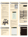
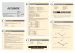
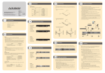
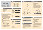
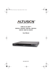
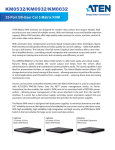
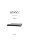
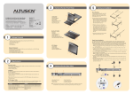
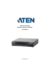
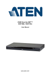
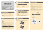
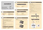
2-2
4
Requirements
Video
1. Power Socket
2. Power Switch
3. Secondary LAN Port
4. PON Port
Only the following non-interlaced video signals are supported:
Resolution
640 x 480
720 x 400
800 x 600
1024 x 768
Online Registration
International:
• http://support.aten.com
North America:
• http://www.aten-usa.com/product_registration
(ATEN TECH)
• http://support.aten.com (ATEN NJ)
KN2124v/KN2140v/KN4124v/KN4140v
KVM Over the NET Quick Start Guide
Technical Phone Support
International:
• 886-2-86926959
North America:
• 1-888-999-ATEN (ATEN TECH)
• 1-732-356-1703 (ATEN NJ)
© Copyright 2009 ATEN International Co., Ltd. www.aten.com
Altusen and the Altusen logo are trademarks of ATEN International Co., Ltd.
All rights reserved. All other trademarks are the property of their respective owners.
®
This product is RoHS compliant
1
PAPE-1215-100G
Printing Date: 03/2009
Package Contents
1 KN2124v, KN2140v, KN4124v, KN4140v KVM Over the Net™ Switch
2 SA0142 Serial Adapters (RJ45-F to DB9-M; DTE to DCE)
1 Grounding Wire
2 Power Cords
1 5-in-1 Console Cable
1 User Manual
1 Rack Mount Kit
1 Quick Start Guide
1 Foot Pad Set (4 pcs.)
2-1
Requirements
Local Client Computers
Local client computers are the ones used to log into the switch over the internet . The following
equipment must be installed on
• For best results we recommend that the computers used to access the switch have at least a P III
1 GHz processor, with their screen resolution set to 1024 x 768.
• Browsers must support 128 bit SSL encryption.
• For best results, a network transfer speed of at least 512kbps is recommended.
• For the Windows Client AP, DirectX 8 must be present, and at least 90MB of memory must be
available after installation.
• For the Java Client AP, the latest version of Sun's Java Runtime Environment (JRE) must be
installed, and at least 145MB of memory must be available after installation.
• For the browser-based WinClient ActiveX Viewer, DirectX 8 must be present, and at least
150MB of memory must be available after installation.
• For the browser-based Java Applet Viewer the latest version of Sun's Java Runtime Environment (JRE) must be installed, and at least 205MB of memory must be available after
installation.
• For the Log Server, you must have the Microsoft Jet OLEDB 4.0 or higher driver installed.
Refresh Rates
60, 70, 72, 75, 85
70, 75
56, 60, 70, 72, 75, 85
60, 70, 75, 85
Resolution
1152 x 864
1152 x 900
1280 x 1024
1600 x 1200
Hardware Review (Rear View)
Refresh Rates
60, 70, 75, 85
66, 76
60, 70, 75, 85
60
1
2
5. Grounding Terminal
6. Primary LAN Port
7. Modem Port
8. Local Console Ports
9. KVM Ports
3 4
KVM Adapter Cables
• Cat 5e (or higher) cable is required to connect the KN2124v / KN2140v /KN4124v / KN4140v
to one of the KVM Adapter Cables
• The following KVM Adapter Cables are required for use with the KN2124v / KN2140v /
KN4124v / KN4140v
Note: If you use Adapter Cables that were purchased prior to your switch purchase, you may
have to upgrade the Adapter Cable’s firmware. You can upgrade the Adapter Cable’s
firmware from the Maintenance page
Function
Connect to devices with PS/2 ports
Connect to devices with USB ports
(all platforms-PC, Mac, Sun)
Connect to Sun Legacy Computers
Connect to serial based devices
Connect to devices with USB ports; virtual media support
Connect to devices with USB ports, virtual media and audio support
KA9170 / KA7170
KA9130 / KA7130
KA9140 / KA7140
KA7175
KA7176
Supported operating systems for Local Client computers that log into the KVM Over the
NETTM switch include Windows 2000 and higher, and those capable of running Sun's Java
Runtime Environment (JRE) 6, Update 3, or higher.
Supported operating systems for the remote servers that are connected to the switch’s ports are
shown in the table, below:
Version
2000 and higher
7.1 and higher
Core 2 and higher
9.0 and higher
9.0 and higher
4.3 and higher
4.2 and higher
Solaris 8 and higher
5.0 and higher
OS 9 and higher*
6.2 and higher
6 7
8
9
Note: The figure above shows the rear panel of a KN2140v / KN4140v with two
blocks of 16 KVM ports and one block of 8 (40 ports in total). The
KN2124v / KN4124v differs in that it only has a single block of 16 KVM
ports and one bock of 8 (24 ports in total).
Module
KA9120 / KA7120
Operating Systems
OS
Windows
Linux
RedHat
Fedora
SuSE
Mandriva (Mandrake)
UNIX
AIX
FreeBSD
Sun
Novell
Netware
Mac
DOS
5
5-1
Hardware Installation 1
Rack Mounting
The KN2124v /KN2140v / KN4124v / KN4140v can be mounted in a 19" (1U) rack. The
mounting brackets can screw into either the front or the back of the unit so that it can attach to
the front or the back of the rack.
To mount the unit at the front of the rack, do the following:
1. Remove the two screws at the front or the rear, as shown in the diagram below:
Phillips head hex
M3 x 6
Browsers
Supported browsers for users that log into the KN2124v / KN2140v / KN4124v/ KN4140v
include the following:
Browser
IE
Firefox
Mozilla
3
Browser
Safari
Opera
Netscape
Version
6 and higher
1.5 and higher
1.7 and higher
Version
2.0 and higher*
9.0 and higher
8.1 and higher
* If Safari freezes when using the
Snapshot feature you may upgrade to
Mac OS 10.4.11 and Safari 3.04.
Phillips head hex
M3 x 6
2. Use the M3 x 8 Phillips head hex screws supplied with the rack mount kit to screw the rack
mounting brackets into the front of the unit:
Phillips head hex
M3 x 8
Hardware Review (Front View)
5. Reset Switch
6. Audio Ports
7. Port Switching Buttons
1. Power LED
2. Port LEDs
3. LAN LEDs
4. USB Ports
2
1
Phillips head hex
M3 x 8
3
Remote Servers
Remote servers are the ones connected to the switch via KVM Adapter Cables. The following
equipment must be installed on these servers:
• A VGA, SVGA or multisync port
• For USB KVM Adapter Cable Connections: a Type A USB port and USB host controller
• For PS/2 KVM Adapter Cable Connections: 6-pin Mini-DIN keyboard and mouse ports
17
18
4
19
20
21
22
23
24
25
26
27
5
28
6
29
30
31
7
32
Note: The figure above shows the front panel of a KN2140v / KN4140v.
The KN2124v / KN4124v differs in that there are fewer port LEDs.
3. Position the device in the front of the rack and align the holes in the mounting brackets with
the holes in the rack.
5-2
6
Hardware Installation 2
In a Single Stage installation, there are no additional switches cascaded from the KN2124v /
KN2140v / KN4124v / KN4140v. To set up a single stage installation, refer to the installation
diagrams (the numbers in the diagram correspond with the numbers of the instruction steps),
and do the following:
1. Use the 5-in-1 Console Cable supplied with the package to connect your Local Console
devices to the unit.
Note: 1. You can use any combination of keyboard and mouse connections. For example,
you can use a PS/2 keyboard with a USB mouse.
2. USB keyboards and mice can plug into the USB ports on the front panel, as well as
into the ports in the console port section.
3. The KN2124v / KN2140v / KN4124v / KN4140v does not support distances that
exceed 20m between itself and the local monitor.
2. Use Cat. 5e cable to connect any available KVM port to a KVM Adapter Cable that is
appropriate for the computer you are installing
3. Plug the connectors on the KVM Adapter Cable into the appropriate ports of the computer
you are installing.
4. Plug a cable from the LAN or WAN into the KN2124v / KN2140v /KN4124v / KN4140v’s
primary network interface socket.
5. (Optional) Plug another cable from the LAN or WAN into the KN2124v /KN2140v /
KN4124v / KN4140v backup (secondary) network interface socket.
6. (Optional) Use Cat. 5e cable to connect the KN2124v / KN2140v /KN4124v / KN4140v‘s
PON port to an SA0142 Adapter. Connect the Adapter to the PON IN port of a PN0108
Power Over the Net™ unit.
7. (Optional) Use Cat. 5e cable to connect the KN2124v / KN2140v /KN4124v / KN4140v's
Modem port to an SA0142 Adapter. Connect the Adapter’s serial connector to the modem’s
DB-9 port.
8. Use the grounding wire supplied with this package to ground the unit by connecting one end
of the wire to the grounding terminal, and the other end of the wire to a suitable grounded
object.
Note: Do not omit this step. Proper grounding helps to prevent damage to the unit from
surges or static electricity.
9. Plug the power cord(s) supplied with this package into the KN2124v /KN2140v / KN4124v
/ KN4140v’s Power Socket, and then into an AC power source. When using a single power
socket, be sure to turn on the correct power switch. When using both power sockets, either
of the power switches can be used to turn on the KVM switch, or turn on both power
switches to enable dual power.
After the KN2124v / KN2140v / KN4124v / KN4140v is cabled up you can turn on the power.
After it is powered up, you can turn on the computers.
Administrator Setup
Once the KN2124v / KN2140v / KN4124v /
KN4140v has been cabled up, the Super
Administrator needs to set the unit up for user
operation using the local console. When the local
console has been connected up and the KN2124v
/ KN2140v / KN4124v / KN4140v turned on, a
login prompt appears on the console monitor:
7
After you have successfully logged in, the KN2124v / KN2140v / KN4124v / KN4140v Main Screen
appears with the Port Access page displayed,
The Control Panel
The Control Panel consists of three rows: a row
of icons at the top, with two text rows below it.
Ordinarily, the top text row shows the video resolution of the remote display, while the lower row
shows the IP address of the device at the remote location at the left and the number of the bus and bus
position that the logged in user is on in the center.
As the mouse pointer moves over the icons in the icon bar, however, the information in the top row
changes to describe the icon's function. If a message is entered in the message board, and you have not
opened the message board in your session, the message scrolls across the bottom row.
Since this is the first time you are logging in, use the default Username: administrator; and the
default Password: password. For security purposes, use the User Management function to
change these to a unique Username and Password
The functions that the icons perform are described in the table below:
Select Device Management → Network to set up the switch for network operation.
2
9
8
2
4
7
Modem
Toggles the display between Full Screen
Mode and Windowed Mode.
Windows Systems:
Note: You must use the generic mouse driver supplied with Windows.
• XP / Server 2003 -- middle position; Enhance pointer precision: off
• 2000 / ME -- Mouse motion: middle position; Acceleration: off
• NT / 98 / 95 -- Mouse speed: slowest
Sun / Linux Systems:
Open a terminal session and issue the following command:
• Sun: xset m 1
• Linux: xset m 0
Click to bring up the Control Panel Configuration
dialog box.
Click to bring up the Message Board.
Click to exit the remote view.
• Exiting from a viewer accessed session brings
you back to the web browser Main Page.
• Exiting from a WinClient AP session logs you
out and brings you back to the login dialog box
• Exiting from a Java Client AP session logs you
out and closes the Java program.
These Lock Key LEDs show the Num Lock, Caps
Lock, and Scroll Lock status of the remote
computer. Click on the icon to toggle the status.
Note: When you first connect, the LED display
may not be accurate. To be sure, click on the LEDs
to set them.
Click to send a Ctrl+Alt+Del signal to the
remote system.
Click to toggle the remote display between
color and gray scale views.
Click to bring up the Virtual Media dialog
box. The icon changes when a virtual
media device is started on the port. This
icon displays in gray when the function is
disabled or not available.
• If you are only using one LAN but connect both ports in case the primary connection fails,
check Redundant NIC; if you are using the secondary LAN port for a second IP address, leave
Redundant NIC unchecked:
• For dynamic IP address assignment, select Obtain an IP address automatically.
• To specify a fixed IP address, select Set IP address manually, and fill in the IP address.
• For automatic DNS Server address assignment, select Obtain DNS Server address
automatically.
• To specify the DNS Server address manually, select Use the following DNS Server, and fill in
the addresses for the Primary and Alternate DNS servers.
• If you are using the secondary LAN port for a second IP address, drop down the list under
Redundant NIC and select Network Adapter 2 and set the IP and DNS addresses for it.
Port Operation
Click on a port in the left panel to switch to that port. The OSD provides a toolbar to help you control
the KN2124v / KN2140v / KN4124v / KN4140v from within the captured port. To bring up the toolbar,
tap the OSD Hotkey (Scroll Lock) twice. The toolbar appears at the upper left corner of the screen.
• Information about the functions that the Toolbar items
perform appears when you move the mouse over them.
• When the toolbar displays, mouse input is confined to the toolbar area and keyboard input has no
effect on the computer connected to the port. To carry out operations on the computer, close the
toolbar by clicking the X on it; or, recall the OSD and select the port again.
8
Specifications
Computer
Connections
Mouse DynaSync is only available for Windows and Mac (OS4.0 or higher).systems connected
to the KN2124v / KN2140v / KN4124v / KN4140v with a KA9170/ KA7170/ KA7175/
KA7176 KVM Adapter, and whose adapter attribute OS setting is configured for Win or Mac
All other configurations must use manual mouse synchronization. These procedures are to be
performed on the computers attached to the KN2124v / KN2140v / KN4124v / KN4140v 's ports
- not on the computer you are using to access the KN2124v / KN2140v / KN4124v / KN4140v.
Click to display a dropdown list of user macros.
Access and run macros more conveniently rather
than using the Macros dialog box
Click to take a snapshot (screen capture) of
the remote display.
To add users, select users in the left pane at the user management page, l, then click Add the
bottom of the main panel.
5-3
Click to select the mouse pointer type.
Note: This icon changes depending on which
mouse pointer type is selected
Click to toggle Automatic or Manual mouse sync.
When the selection is Automatic, a green √ appears
on the icon.
When the selection is Manual, a red X appears on
the icon.
Click to toggle the local computer’s speaker on or
off.
Click to perform a video and mouse
autosync operation. It is the same as
clicking the Auto-sync button in the Video
Options dialog box
Select User Management → administrator → Modify to change the default Super Administrator
username and password to something unique
Hardware Installation 3
Click to bring up the on-screen keyboard
Click to bring up the Macros dialog box
Click to bring up the Video Options dialog
box. Right-click to perform a quick Auto
Sync
PN0108
3
Click to zoom the remote display window.
Note: This feature is only available in windowed
mode (Full Screen Mode is off).
This is a toggle. Click to make the Control
Panel persistent – i.e., it always displays on
top of other screen elements. Click again to
have it display normally.
6
5
Operation
Console
Connections
Port Selection
Function
Direct
Max
Local
Remote
Keyboard
Video
Mouse
KVM Ports
Power
Connectors LAN
Modem
USB
PON
Audio
Reset
Switches
Power
Port Selection
On Line
Selected
Power
LEDs
Link 10/100/1000 Mbps
Emulation Keyboard/Mouse
Video
Scan Interval
I/P Rating
Single Power
Power
Consumption Dual Power
Operating Temp.
Environment Storage Temp.
Humidty
Housing
Physical
Weight
Properties
Dimensions (LxWxH)
KN2124v
24
384 (via Cascade)
Console
Ports
1
2
KN2140v
40
640 (via Cascade)
KN4124v
24
384 (via Cascade)
OSD, Hotkey, Pushbutton
1
4
KN4140v
40
640 (via Cascade)
1 x SPHD-18 (F)
24 x RJ-45 (F)
40 x RJ-45(F)
24 x RJ-45(F)
2 x 3-prong AC Socket
2 x RJ-45 Female (Black)
1 x RJ-45 Female (Black)
3 x USB Type A Female (White)
1 x RJ-45 Female (Black)
2 x Audio Jack Female
1 x Semi-recessed Pushbutton
2 x Rocker Switch
2 x Pushbutton
24 (Green)
24 (Red)
1 (Blue)
2 (Red/Red + Green/Green)
PS/2, USB (PC, Mac, Sun); Serial
1600 x 1200 @60Hz
1-255 Seconds
100-240 VAC; 50-60Hz; 1A
115V/36.4W; 230V/37.2W 115V/36.8W; 230V/37.7W 115V/43.7W; 230V/44.6W
115V/41.8W; 230V/42.5W 115V/42.2W; 230V/43W 115V/49.1W; 230V/50W
0-50°C
-20-60˚C
0-80% RH, Non-condensing
Metal
5.99 kg
6.08 kg
6.04 kg
43.36 x 40.94 x 4.40 cm (19”1U)
40 x RJ-45(F)
115V/49W; 230V/50W
115V/54W; 230V/56W
6.12 kg