1
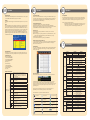
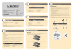
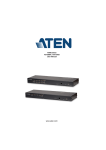
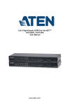
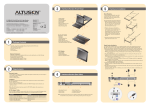
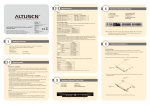
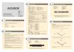
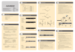
3
5-2
Hardware Review (Front View)
Hardware Installation
1&2
Single Station Installation
(KH1516Ai)
3
1.
2.
3.
4.
Online Registration
• http://eservice.aten.com
KH1508Ai / KH1516Ai Cat 5 High-Density
KVM Over the NET™ Quick Start Guide
®
© Copyright 2012 ATEN International Co., Ltd. www.aten.com
Altusen and the Altusen logo are trademarks of ATEN International Co., Ltd.
All rights reserved. All other trademarks are the property of their respective owners.
This product is RoHS compliant
PAPE-1214-Y30G
Printing Date: 09/2012
Technical Phone Support
International:
• 886-2-8692-6959
China:
• 86-10-5255-0110
Japan:
• 81-3-5615-5811
Korea:
• 82-2-467-6789
North America:
• 1-888-999-ATEN Ext: 4988
United Kingdom:
• 44-8-4481-58923
All information, documentation, and specifications contained in this media are subject to change without prior notification by the manufacturer.
Please visit our website to find the most up to date version.
Port Selection Pushbuttons
Port LEDs
Reset Switch
Laptop USB Console Port
4
5.
6.
7.
8.
6
7
8
Firmware Upgrade Recovery Switch
Firmware Upgrade Port
Power LED
Station ID LED
Hardware Review (Rear View)
1
1
4 5
2 3
4
5
Package Contents
1 KH1508Ai or KH1516Ai Cat 5 High-Density
KVM Over the NET™ Switch
1 Firmware Upgrade Cable
1 Laptop USB Console Cable
1 Power Cord
1 Rack Mount Kit
1 Foot Pad Set (4 pcs.)
1 User Instructions
2
(KH1516Ai)
Important Notice
Considering environmental protection, ATEN
does not provide a fully printed user manual for
this product. If the information contained in the
Quick Start Guide is not enough for you to
configure and operate your product, please visit
our website www.aten.com, and download the
full user manual.
6
1.
2.
3.
4.
Power Socket
Power Switch
LAN Port
PON Port
General
• For best results, we recommend that the computers used to access the KH1508Ai / KH1516Ai have
at least a P III 1 GHz processor, and that their screen resolution is set to 1024 x 768
• For best results, we recommend an Internet connection speed of at least 128 kbps
• Browsers must support 128 bit data encryption
• To run the Windows client, you must have DirectX 8.0 or higher installed
• To run the Java client, you must have Sun’s JRE 6 update 3 or higher installed
• To run the Log Server, you must have the Microsoft Jet OLEDB 4.0 (or higher) driver installed
8
5.
6.
7.
8.
Daisy Chain Port
Grounding Terminal
Local Console Port Section
KVM Port Section
After the KH1508Ai / KH1516Ai is cabled up, you can turn on the power. After it is powered up, you can turn on the
servers.
Note: The front and rear panel views are similar for the KH1508Ai, the difference being that the
KH1508Ai has only one row of LED lights (front) and one row of CPU ports (rear)
5-1
Requirements
7
In a single stage installation, there are no additional KVM switches daisy chained down from the KH1508Ai /
KH1516Ai. To set up a single stage installation (the numbers in the diagram correspond with the numbers of the
instruction steps), and do the following:
1. Ground the KH1508Ai / KH1516Ai by connecting one end of the grounding wire to the grounding terminal, and
the other end of the wire to a suitable grounded object.
Note: Do not omit this step. Proper grounding helps to prevent damage to the unit from surges or static
electricity.
2. Plug the console keyboard, monitor, and mouse into the unit’s console ports. The ports are color coded and
marked with icons for easy identification.
Note: You can use any combination of keyboard and mouse connections. For example, you can use a PS/2
keyboard with a USB mouse.
3. If you are using a laptop to control the KH1508Ai / KH1516Ai locally, use the Laptop USB Console Cable
included in the package to connect the laptop to the KH1508Ai / KH1516Ai’s Laptop USB Console port, located
on the unit’s front panel.
4. Use Cat 5e/6 cable to connect any available KVM port to a KVM adapter cable that is appropriate for the
computer you are installing
Note: To support a resolution of 1280x1024@75Hz, the recommended maximum distance between the unit and
the KVM adapter cable is 50 meters; to support a resolution of 1600x1200@60Hz, the recommended
maximum distance is 40 meters.
5. Connect the KVM adapter cable to the computer.
Plug the connectors on the KVM adapter cable into the appropriate ports of the computer you are installing.
6. Plug the LAN or WAN cable into the KH1508Ai / KH1516Ai’s LAN port.
7. Plug the female end of the power cord into the KH1508Ai / KH1516Ai's power socket; plug the male end into an
AC power source.
3
Rack Mounting
5
6
Hardware Installation
4
7
The KH1508Ai / KH1516Ai can be mounted in a 19" (1U) racks. The mounting brackets can screw into either the
front or the back of the unit so that it can attach to the front or the back of the rack. To rack mount the unit:
1. Remove the screws at the front or the rear, as shown in the diagram below.
1
Phillips head hex
M3 x 6
Console
• A VGA, SVGA, or Multisync monitor capable of the highest resolution that you will be using on
any computer in the installation.
• A USB or PS/2 style mouse
• A USB or PS/2 style keyboard
Phillips head hex
M3 x 6
2
Computers
The following equipment must be installed on the computers that connect to the KH1508Ai or
KH1516Ai's KVM ports:
• A VGA, SVGA or Multisync port
• A Type A USB port and USB host controller (for USB KVM Adapter Cable Connection, see
below)
• 6-pin mini-DIN keyboard and mouse ports (for PS/2 KVM Adapter Cable Connection, see below)
2. Screw the mounting brackets into the sides of the unit at the front or the rear, as shown in the diagram below.
Phillips head hex
M3 x 8
2
KVM Adapter Cables
• Cat 5e/6 cable is required to connect the KH1508Ai / KH1516Ai to one of the KVM adapter cables.
• The following KVM adapter cables are required for use with the KH1508Ai / KH1516Ai:
Function
Connect to devices with PS/2 ports
Connect to devices with USB ports
Connect to Sun Legacy systems (with 13W3 port)
Connect to Sun USB systems
Connect to serial based devices
4
Module
KA7920 / KA7520 / KA7120 / KA9520 / KA9120
KA7970 / KA7570 / KA7170 / KA9570 / KA9170
KA9130 / KA7130
KA9170 / KA7170
KA9140
3. Slide the unit into the front or rear of the rack and secure it to the rack.
6-1
6-2
Operation
Basic Operation
KH1508Ai / KH1516Ai installations provide five methods to obtain instant access to any computer
in your installation: Manual, OSD, Hotkey, Laptop Console, and GUI
Manual
For manual port selection, simply press the Port Switch that corresponds to the device you wish to
access.
OSD
OSD (On Screen Display), provides a text-based menu driven interface to the computer switching
procedure. All procedures start from the OSD Main Screen. To display the Main Screen, tap the
OSD hotkey twice. The default hotkey is [Scroll Lock]. Before the OSD Main Screen comes up, a
login dialog box appears requesting a username and password. You must provide a valid username
and password in order to continue. The first time that the OSD is accessed, you must use the
default username and password. The default username is administrator; the default password is
password. After logging in with the default username and password, the OSD Main Screen opens
in Administrator mode as below.
6-3
Operation
Local Console Login
When the local console is attached and there is no user logged in, the KH1508Ai / KH1516Ai login
screen appears on the monitor. Simply key in your valid Username and Password, then click Login
to bring up the Local Console Main Page. The Local Console Main Page is similar to the Web
Browser, WinClient and Java Client Main Pages .
Laptop USB Console Login
Use an appropriate USB cable to connect your laptop to the KH1508Ai /
KH1516Ai’s laptop USB console port, located on the unit’s front panel. The KH1508Ai /
KH1516Ai appears as a virtual drive in the laptop’s file system. Locate the laptop console AP on the
virtual CD ROM and double click the ALTUSEN icon. The login screen appears
Operation
Port Operation
The KH1508Ai / KH1516Ai KVM Over the NET™ switch’s interface provides a toolbar to help you
with port switching operations from within the captured port. To bring up the toolbar, tap the GUI
Hotkey (Scroll Lock or Ctrl) twice. The toolbar appears at the upper left corner of the screen.
Note: 1. You can adjust the toolbar transparency.
2. The toolbar functions and icons are also incorporated in the Control Panel. If you choose to
enable them in the Control Panel, you can disable the Toolbar . To recall the Port Access
Connections page when there is no Toolbar, simply tap the GUI hotkey twice.
Browser Login
Open an Internet browser and specify the IP address of the switch you want to access in the
browser's location bar.
Note: For security purposes, a login string may have been set by the administrator. If so, you must
include a forward slash and the login string along with the IP address when you log in.
For example: 192.168.0.100/kh1516ai
If you don't know the IP address and login string, ask your Administrator.
Windows Client / Java Client AP Login
To connect to the KH1508Ai / KH1516Ai, go to the location on your hard disk that you downloaded
the Windows AP Client / Java AP Client program to, and double-click its icon to bring up the
Windows Client Connection Screen
GUI Main Page
Once you have successfully logged in, the KH1508Ai / KH1516Ai user interface Main Page appears
with the Port Access page displayed. The look of the page varies slightly, depending on which
method you used to log in.
Keyboard Hotkeys
Invoking Hotkey Mode
Number Lock and Minus Keys
1. Hold down the Num Lock key;
2. Press and release the minus key;
3. Release the Num Lock key:
[Num Lock] + [-]
Console
Port
Control and F12 Keys
1. Hold down the Ctrl key;
2. Press and release the F12 key;
3. Release the Ctrl key:
[Ctrl] + [F12]
[A] [Enter]
[B]
[Esc] or
[Spacebar]
[F1]
[F2]
[F3]
[F5]
[H]
[Num Lock] + [-] [Port ID]
or [Ctrl] + [F12] [Enter]
Specifications
Function
Direct
Computer
Connections Maximum
Port Selection
Hotkeys allow you to conveniently provide KVM focus to a particular computer from the local
console keyboard, instead of having to manually select them by pressing Port Selection switches
Hotkey Summary Table
7
Connectors
Invokes Auto Scan mode. When Auto Scan mode is in
effect, [P] or left-click pauses auto-scanning. When autoscanning is paused, pressing any key or another left-click
resumes auto-scanning.
Toggles the Beeper On or Off.
Exits hotkey mode.
Sets Operating System to Windows
Sets Operating System to Mac
Sets Operating System to Sun
Performs a keyboard / mouse reset on the target computer.
Toggles the Hotkey invocation keys.
Switches access to the computer that corresponds to that
Port ID.
Administrator only hotkey. It returns the switch’s settings
[R] [Enter]
to their default values.
Toggles the OSD Hotkey between [Ctrl] [Ctrl] and [Scroll
[T]
Lock] [Scroll Lock].
Invokes Skip Mode and skips from the current port to the
[ ]
first accessible port previous to it.
Invokes Skip Mode and skips from the current port to the
[ ]
next accessible port.
Invokes Skip Mode and skips from the current port to the
[ ]
last accessible port of the previous Station.
Invokes Skip Mode and skips from the current port to the
[ ]
first accessible port of the next Station.
The Control Panel
The Control Panel consists of three rows: a row of icons at the top, with two text rows below it.
Switches
By default, the upper text row shows the video resolution of the remote display. As the mouse
pointer moves over the icons in the icon bar, however, the information in the upper text row
changes to describe the icon's function. In addition, if a message from another user is entered in the
message board, and you have not opened the message board in your session, the message will
appear in the upper row.
The lower row shows the IP address of the device you are accessing at the left of the row.
Right clicking in the text row area brings up a menu-style version of the toolbar
The functions that the icons perform are described in the table below:
LEDs
Emulation
Video
Control Panel
Message Board
Automatic mouse sync
Macros
Click to send a
Ctrl+Alt+Del
User macros list
Video Options
Toggle color and gray
scale views
Control Panel
Configuration
Video and mouse
autosync operation
Zoom in
Exit
Full Screen Mode
On-screen keyboard
Lock indicator
Snapshot
Mouse pointer type
Keyboard
Video
Mouse
KVM Port
Daisy Chain Ports
Power
LAN
F/W Upgrade
PON
Laptop USB Console
(LUC)Port
Reset
Power
Port Selection
On Line
Selected
Power
Station ID
Link
10 / 100Mbps
Keyboard/Mouse
Local
Remote
Scan Interval
I/P Rating
Power Consumption
Operating Temp.
Environment Storage Temp.
Humidity
Housing
Physical
Weight
Properties
Dimensions
(LxWxH)
KH1508Ai
KH1516Ai
8
16
128 (via daisy chain)
256 (via daisy chain)
OSD; Hotkey; Pushbutton
1 x 6-pin Mini-DIN Female (Purple)
1 x USB Type A Female (White)
1 x HDB-15 Female (Blue)
1 x 6-pin Mini-DIN Female (Green)
1 x USB Type A Female (White)
8 x RJ-45 Female
16 x RJ-45 Female
1 x DB-25 Male (Black)
1 x 3-prong AC socket
1 x RJ-45 Female
1 x RJ-11 Female (Black)
1 X RJ-45 Female
1 x USB Mini Type B Female (Black)
1 x Semi-recessed Pushbutton
1 x Rocker
8 x Pushbutton
16 x Pushbutton
8 (Green)
16 (Green)
8 (Orange)
16 (Orange)
1 (Blue)
1 x 2-digit 7-segment (Orange)
1 (Orange)
1 (Orange / Green)
PS/2, USB
1600 x 1200 @ 60 Hz (40m) ;
1280 x 1024 @ 75 Hz
(50 m with KA7xx Adapter Cable)
1600 x 1200 @ 60Hz
1-255 secs
100-240 VAC; 50/60 Hz; 1A
120V/12.5W; 230V/12.7W
0-50°C
-20-60°C
0-80% RH; Non-condensing
Metal
2.80 kg
43.70 x 16.10 x 4.40 cm (19"/1U)