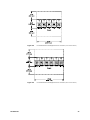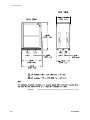
1
SGI® Origin® 3900 Server Site Planning Guide 007-4603-001 CONTRIBUTORS Written by Allison Gosbin Illustrated by Brian Stickney Edited by Cindi Leiser Production by Rhonda Kunsman Engineering contributions by Gary Spilde and Brian Stickney COPYRIGHT © 2003 Silicon Graphics, Inc. All rights reserved; provided portions may be copyright in third parties, as indicated elsewhere herein. No permission is granted to copy, distribute, or create derivative works from the contents of this electronic documentation in any manner, in whole or in part, without the prior written permission of Silicon Graphics, Inc. LIMITED RIGHTS LEGEND The electronic (software) version of this document was developed at private expense; if acquired under an agreement with the USA government or any contractor thereto, it is acquired as "commercial computer software" subject to the provisions of its applicable license agreement, as specified in (a) 48 CFR 12.212 of the FAR; or, if acquired for Department of Defense units, (b) 48 CFR 227-7202 of the DoD FAR Supplement; or sections succeeding thereto. Contractor/manufacturer is Silicon Graphics, Inc., 1600 Amphitheatre Pkwy 2E, Mountain View, CA 94043-1351. TRADEMARKS AND ATTRIBUTIONS SGI, Silicon Graphics, IRIX, Octane, Origin, and the SGI logo are registered trademarks, and NUMAlink and XIO are trademarks of Silicon Graphics, Inc., in the United States and/or other countries worldwide. MIPS is a registered trademark of MIPS Technologies, Inc. used under license by Silicon Graphics, Inc. Record of Revision 007-4603-001 Version Description 001 February 2003 Original publishing. iii Contents Record of Revision . . . . . . . . . . . . . . . . . . . . iii Figures . . . . . . . . . . . . . . . . . . . . . . . . vii Tables . . . . . . . . . . . . . . . . . . . . . . . . ix About This Guide . . What This Guide Contains Audience for This Guide Obtaining Publications . Reader Comments . . . . . . . . . . . . . . . . . . . . . . . . . . . . . . . . . . . . . . . . . . . . . . . . . . . . . . . . . . . . . . . . . . . . . . . . . . . . . . . . . . . . . . . . . . . . . xi . xi . xii xiii xiii 1. Overview . . . . . . . . . . . . . . . . . . . . 1 2. Site Preparation Concepts . . . . Physical Location . . . . . . . Selecting a Delivery Route . . . Selecting a Final Location . . . . . Electrical Requirements . . . . . Voltage Requirements . . . . . Power Requirements . . . . . Grounding Requirements . . . . Power Factor . . . . . . . Inrush Current . . . . . . . Power-line Treatment . . . . . Total Harmonic Distortion . . . . Thermal Requirements . . . . . . Heat Output . . . . . . . Air-conditioning Terminology . . . Calculating Thermal Load . . . . Thermal Gradient . . . . . . Cooling In Mission-critical Installations Environmental Requirements . . . . Electromagnetic Interference . . . Electrostatic Discharge . . . . Vibration . . . . . . . . Humidity . . . . . . . . Humidity Gradient . . . . . . . . . . . . . . . . . . . . . . . . . . . . . . . . . . . . . . . . . . . . . . . . . . . . . . . . . . . . . . . . . . . . . . . . . . . . . . . . . . . . . . . . . . . . . . . . . . . . . . . . . . . . . . . . . . . . . . . . . . . . . . . . . . . . . . . . . . . . . . . . . . . . . . . . . . . . . . . . . . . . . . . . . . . . . . . . . . . . . . . . . . . . . . . . . . . . . . . . . . . . . . . . . . . . . . . . . . . . . . . . . . . . . . . . . . . . . . . . . . . . . . . . . . . . . . . . . . . . . . . . . . . . . . . . . . . . . . . . . . . . . . . . . . . . . . . . . . . . . . . . . . . . . . . . . . . . . . . 3 . 3 . 3 . 4 . 5 . 6 . 6 . 7 . 7 . 7 . 8 . 8 . 9 . 9 . 9 . 10 . 10 . 11 . 11 . 11 . 12 . 12 . 12 . 12 007-4603-001 . . . v Contents Ergonomic Requirements Acoustics . . . Local Regulations . . Planning for the Future . vi . . . . . . . . . . . . . . . . . . . . . . . . . 13 . 13 . 13 . 13 3. SGI Origin 3900 Server Features, Configurations, and Components . SGI Origin 3900 Server Configurations . . . . . . . . . SGI Origin 3900 Server Bricks . . . . . . . . . . . . System Control . . . . . . . . . . . . . . . . L1 Controller . . . . . . . . . . . . . . . L2 Controller . . . . . . . . . . . . . . . L3 Controller . . . . . . . . . . . . . . . . . . . . . . . . . . . . . . . . . . . . . . . . . . . . . . . . . . . 15 . 16 . 17 . 19 . 19 . 19 . 19 4. SGI Origin 3900 Server Layout . . . . . . . . . . . . . . . . . 21 5. System Physical Specifications . . . . . . . . . . . . . . . . . 25 6. Site Requirements . . . Planning Your Access Route Environmental Requirements System Power Requirements Remote Support. . . . Network Connections . . Raised-floor Installations . . . . . . . . . . . . . . . . . . . . . . . . . . . . . . . . . . . . . . . . . . . . . . . . . . . . . . . . . . . . . . . . . . . . . . . . . . . . . . . . . . . . . . . . . . . . . . . . . . . . . . . . . . . . . . . . . . . . . . . . . 29 . 29 . 31 . 32 . 34 . 34 . 35 7. Securing the Cabinets . . . . . . . . . . . . . . . . . . . . 39 8. Site Planning Checklist . . . . . . . . . . . . . . . . . . . 41 9. Summary . . . . . . . . . . . . . . . . . . . . 43 A. U.S. Customary Measure and Metric Measure Conversion Fahrenheit-to-Celsius Conversion . . . . . . . . Celsius-to-Fahrenheit Conversion . . . . . . . . . . . . . . . . . . . . . . . . . . . . . . . . . 45 . 46 . 46 B. Regulatory Specifications . . . . . . . . . . Manufacturer's Regulatory Declarations . . . . . . System Model Number . . . . . . . . . CE Notice and Manufacturer's Declaration of Conformity Electromagnetic Emissions . . . . . . . . FCC Notice (USA Only) . . . . . . . . Industry Canada Notice (Canada Only) . . . . VCCI Notice (Japan Only) . . . . . . . Chinese Class A Regulatory Notice . . . . . Korean Class A Regulatory Notice . . . . . Shielded Cables . . . . . . . . . . . . . . . . . . . . . . . . . . . . . . . . . . . . . . . . . . . . . . . . . . . . . . . . . . . . . . . . . . . . . . . . . . . . . . . . . . . . . . . . . . . . . . . . . . . . 47 . 47 . 47 . 47 . 48 . 48 . 48 . 49 . 49 . 49 . 49 . . . . . . . . . . . . . . . . . . . . . . . . . . . . . . . . . . . . . . . . . . . . . . . . . . . 007-4603-001 Figures Figure 3-1 Figure 4-1 Figure 4-2 Figure 4-3 Figure 4-4 Figure 4-5 Figure 5-1 Figure 6-1 Figure 6-2 Figure 6-3 Figure 7-1 007-4603-001 Typical Origin 3900 Series Server Configurations . . . . Overall Dimensions and Required Service Clearances (1 to 6 Cx-bricks) . . . . . . . . . . . . Overall Dimensions and Required Service Clearances (8 to 12 Cx-bricks) . . . . . . . . . . . . Overall Dimensions and Required Service Clearances (14 to 16 Cx-bricks) . . . . . . . . . . . . Overall Dimensions and Required Service Clearances (18 to 24 Cx-bricks) . . . . . . . . . . . . Overall Dimensions and Required Service Clearances (26 to 32 Cx-bricks) . . . . . . . . . . . . SGI Origin 3900 Compute Rack, Router Rack, and I/O Rack . SGI Origin 3900 Compute Rack, Router Rack, or I/O Rack Shipping Container . . . . . . . . . . . . SGI Origin 3900 Compute Rack, Router Rack, or I/O Rack Floor Cutout Location (Shown on 24 in. x 24 in. Floor Panels) SGI Origin 3900 Compute Rack, Router Rack, or I/O Rack Caster and Leveling Pad Locations . . . . . . . . SGI Origin 3900 Compute Rack, Router Rack, or I/O Rack Weld Nut Locations . . . . . . . . . . . . . 18 . 21 . 22 . 22 . 23 . 23 . 27 . 30 . 36 . 37 . 39 vii Tables Table 2-1 Table 3-1 Table 5-1 Table 6-1 Table 6-2 Table 8-1 Table A-1 007-4603-001 Electrical Service Requirements. . . . . . . Origin 3900 System Brick Types, Functions, and Heights Physical Specifications for the SGI Origin 3900 Server System Environmental Requirements (Maximum) . . Electrical Specifications for the Origin 3900 Server . Site Planning Checklist . . . . . . . . . U.S. Customary-to-Metric Conversions . . . . . . . . . . . . . . . . . . . . 5 . 17 . 26 . 31 . 32 . 41 . 45 ix About This Guide What This Guide Contains The SGI Origin 3900 Server Site Planning Guide contains the following chapters: Chapter 1, “Overview” Describes the information that helps management and site preparation personnel prepare for an SGI Origin 3900 server system installation. It includes general site planning concepts as well as specific site specifications and requirements that you may use as a guide during the site planning and preparation process. Chapter 2, “Site Preparation Concepts” Describes the site planning process and provides a detailed discussion of the issues involved in any site preparation. For specific Origin 3900 site planning information, refer to the subsequent sections of this guide. Chapter 3, “SGI Origin 3900 Server Features, Configurations, and Components” Describes the configuration classes, brick types, and cooling requirements for the Origin 3900 server. Chapter 4, “SGI Origin 3900 Server Layout” Describes the floor panels and layouts for a typical Origin 3900 server system. Chapter 5, “System Physical Specifications” Describes the specifications for both the Origin 3900 rack system and the system components in detail. Chapter 6, “Site Requirements” Describes the information and guidelines that are necessary to plan your access route and to meet the environmental and power requirements for your system. Chapter 7, “Securing the Cabinets” Describes the four M12 threaded weld nut locations that are used to secure each Origin 3900 system to the computer room subfloor. Chapter 8, “Site Planning Checklist” Describes the site planning checklist that you can use as an organizational tool during the site planning and preparation process. 007-4603-001 xi About This Guide Chapter 9, “Summary” Describes the methods that are available for contacting your SGI site planning representative. Appendix A, “U.S. Customary Measure and Metric Measure Conversion” Describes the conversions between U.S. customary and metric measures, Fahrenheit-to-Celsius temperature, and Celsius-to-Fahrenheit temperature. Appendix B, “Regulatory Specifications” Describes several national and international specifications to which the Origin 3900 system conforms. Audience for This Guide This guide is intended for people who are responsible for physical site planning and preparation. By planning for your SGI Origin 3900 server system installation, you will have the opportunity to make adjustments to your site and order any additional facility equipment, thereby reducing the time required to install your system. xii 007-4603-001 Obtaining Publications Obtaining Publications To obtain SGI documentation, go to the SGI Technical Publications Library at http://docs.sgi.com. Reader Comments If you have comments about the technical accuracy, content, or organization of this document, please tell us. Be sure to include the title and document number of the manual with your comments. (Online, the document number is located in the front matter of the manual. In printed manuals, the document number is located on the front cover.) You can contact us in any of the following ways: • Send e-mail to the following address: [email protected] • Contact your customer service representative and ask that an incident be filed in the SGI incident tracking system. • Send mail to the following address: SGI Site Planning 890 Industrial Blvd. P.O. Box 4000 Chippewa Falls, WI 54729-0078 USA • Send a fax to the attention of “Site Planning” at +1 715 726 2969. We value your comments and will respond to them promptly. 007-4603-001 xiii Chapter 1 1. Overview This document provides information that helps management and site preparation personnel prepare for an SGI Origin 3900 server system installation. It includes general site planning concepts as well as specific site requirements that you may use as a guide during the site planning and preparation process. SGI site planning representatives are available in the United States of America for site planning consultation; contact a site planning representative by telephone in the USA at +1 888 744 8638, extension 676-2820; at +1 715 726 2820; by fax at +1 715 726 2969; or by e-mail at [email protected]. Contact your account manager to discuss your site planning, preparation, and installation plans and to obtain configuration information for any system. Use the following steps as a planning guide for your system installation: 1. Identify the space, power, and environmental requirements for the system. 2. Select a location for the system and identify any necessary modifications. 3. Prepare the site according to the guidelines in this publication. You may use the site planning checklist in Chapter 8 of this document as a guide. 007-4603-001 1 Chapter 2 2. Site Preparation Concepts This chapter of the SGI Origin 3900 Server Site Planning Guide provides a general overview of the site planning process and information about the issues that are involved in any site preparation. For the system-specific site planning information, refer to the subsequent chapters of this document. Not all of the items listed here apply to every installation; however, it is a good idea to briefly consider each question for any system installation. Physical Location This section addresses the issues that you need to consider when you select a physical location for a new system. Selecting a Delivery Route To ensure that the system can be delivered to the planned location, answer the following questions before you plan a delivery route for the new system: • Will the shipping crate fit through doorways and hallways and on elevators? In addition to measuring the width of the hallways along the planned delivery route, measure corners where the system might get stuck, the width and height of doorways and elevators, and other areas that may cause problems. Table 5-1 lists the relevant system dimensions. • If the shipping crate cannot be transported to the final destination, can you unpack the system somewhere else? Often it is possible to unpack the system in a hallway or on a loading dock, and then roll the system to its final destination. 007-4603-001 3 2: Site Preparation Concepts • Is the floor strong enough to support the weight of the system? The rack loaded with bricks can be very heavy. Determine the weight of each rack and verify that the floor along the delivery route can handle the weight. Refer to Table 5-1 for the maximum weight per system rack. • Is the elevator capable of lifting the system? If the intended delivery route includes an elevator, check its weight capacity and size against the system specifications listed in Table 5-1. The use of freight blankets can reduce damage to the elevator or the system. • Are there any steep angles, bumps, changes in level, or thick carpeting along the delivery route? Large systems are typically equipped with casters. However, the casters are designed to roll easily only on relatively smooth, level surfaces. Ramps, sliding door channels, rough flooring, and even thick carpeting may present difficulty. If in doubt, arrange for additional assistance. The maximum access incline should not exceed 10 degrees (height:length = 1:6). • Did you ensure that the leveling pads are fully retracted? Some systems have screw-in leveling pads. If you move the system with these feet extended, severe damage to the chassis can occur. These feet sometimes unscrew during shipment. Before you unpack or move a system, ensure that the leveling pads are fully retracted. Refer to Figure 6-3 for leveling pad locations. Selecting a Final Location Consider the following issues when you select a final location for the system: • Will the system fit in its intended location? Carefully calculate the total system dimensions to ensure that it will fit in its intended final location. • Does the intended system location provide adequate access space for maintenance? Even if the system will fit in its intended final location, you must have room to maintain it. Ensure that you will have enough room to open the doors, remove boards, and accomplish other routine tasks. Table 5-1 lists the relevant system dimensions and access requirements. • Is the intended location subject to flooding, extremes of humidity or temperature, or any other factor that would make it inappropriate for sensitive electronic equipment? The air temperature should not be too high and should not fluctuate dramatically, air should circulate freely and be relatively dust-free, and the system should not be exposed to any caustic or corrosive chemicals or vapors. Refer to Table 6-1 for system-specific requirements. • 4 Will the system interfere with normal traffic through aisles, hallways, or entrance ways in the intended location? 007-4603-001 Electrical Requirements • Will the intended location enable you to conveniently perform routine operations, such as loading and unloading tapes or other media, attaching cables, and so on? • Is the floor of the intended final location strong enough to support the weight of the system and any future expansions? Large systems should be installed in computer rooms with raised floors. Pay particular attention to floor loading and weight distribution in this case. Floor-loading specifications are typically calculated by averaging the total chassis weight that is distributed over the entire footprint of the chassis. Because the chassis sits on four casters or four leveling pads, the load at each of these four points is greater. • Have you considered the site preparation cost and ease of installation at this location? • Does the intended location of the system allow for future expansion plans? Electrical Requirements SGI Origin 3900 server systems require electrical resources beyond those that are normally provided in a typical office environment. The following sections describe those requirements in general. These sections, along with the data presented in subsequent sections, can help you determine the exact requirements for the new system. Table 2-1 lists the electrical service requirements. Table 2-1 007-4603-001 Electrical Service Requirements Electrical Service Requirement Phase imbalance 5% maximum (line-to-line, line-to-neutral) Voltage harmonics 5% maximum total, 3% largest Voltage deviation from sine wave +5% to -10% Voltage modulation 3% maximum Transient voltage surges +5% Transient voltage sags -5% Frequency tolerance 5% Frequency rate of change Less than 1.0 Hz during any 10-cycle period 5 2: Site Preparation Concepts Voltage Requirements SGI Origin 3900 servers ship with the option of either single-phase or three-phase input power. Refer to the section titled “System Power Requirements” in Chapter 6 for the voltage requirements of the chassis. You must ensure that your account manager knows of your needs before the system is ordered. Ensure that the required voltage is available and is within a reasonable distance of the intended location. If it is not, the site must be wired for the required voltage. Power Requirements Even one SGI Origin 3900 server rack can require more power than is routinely available in an office environment. A room full of racks will almost certainly require some specially installed electrical circuits. Refer to the section titled “System Power Requirements” in Chapter 6 for the power requirements of the rack in question. Note: The wattages listed in this guide are the system maximums. While most systems never draw the maximum rated wattage, SGI recommends that you install wiring that is capable of supporting the system’s maximum potential wattage. Power is measured in voltamperes (VA) and watts. Both measurements are important when you prepare to install wiring, power conditioning, and cooling. A VA rating is a function of the voltage and amperage of a system. A watt rating is the VA rating multiplied by its power factor (refer to the section titled “Power Factor” on page 7). You can convert among amps, volts, VA, power factor, and watts by using the following formulas: Single Phase Three Phase VA = (Amps . Volts) VA = (Amps . Volts . 1.73) Watts VA = Power Factor Watts VA = Power Factor Watts = (VA . Power Factor) Watts = (VA . Power Factor) Amps = Watts Volts . Power Factor Amps = Watts Volts . Power Factor .1.73 Use this information and the information provided in Table 6-2 to determine the site power requirements. If, after you add up the power requirements of all the devices in the room, you find that the total is close to the limit that the existing wiring can support, you should install additional power circuits to support the systems. 6 007-4603-001 Electrical Requirements Grounding Requirements • Ensure that the ground has sufficiently low impedance in order to limit the voltage to ground and to facilitate the operation of protective devices in the electrical circuit. • Ensure that all grounds entering the room are interconnected somewhere within the building to provide a common ground potential. This includes any separate power sources, lighting, convenience outlets, and other grounded objects such as building steel, plumbing, and ductwork. Refer to the IEEE Emerald Book: IEEE Recommended Practices for Powering and Grounding Electronic Equipment and the National Electric Code (NEC) for power, grounding, and life safety issues. Warning: Any difference in ground potential greater than 250 millivolts between two racks that are connected with NUMAlink or Xtown cables can cause severe equipment damage. • To maintain your entire SGI Origin 3900 server at the same electrical potential, all multiple-rack systems must be bolted together. Power Factor Power factor is a number between 0 and 1 that represents the ratio of the total power in watts to the total volt-amperage input. A system with a power factor of one (sometimes called “unity”) is making full use of the energy that it draws. A system with a power factor of 0.75 is effectively using only three-quarters of the energy that it draws. SGI Origin 3900 servers are power-factor corrected and thus have a power factor very close to 1. Some peripherals do not have this correction built in. Caution: Ensure that you consider the power factor of the system when you select an uninterruptible power supply (UPS). Inrush Current Inrush current is the peak current that flows into a power supply as AC power is applied. The inrush current is usually much higher than the nominal current. This temporary increase is due to the charging of the input filter capacitors in the power supply and is limited only by the input impedance of the power supply and the wiring that supplies power to the system. The inrush current often far exceeds the rating of the electrical outlet to which the system is connected. If the system is connected directly to “wall power” (that is, it is not on a UPS or a standby power system [SPS] ), this is typically not a problem. The peak inrush current lasts for only a part of one AC cycle (less than 1/60 of a second). This is not long enough to damage wiring and, in most cases, will not trip a circuit breaker (depending on the delay curves of the circuit breaker). 007-4603-001 7 2: Site Preparation Concepts It is very important that you consider the inrush current of the system when you select a UPS or SPS. Unlike power-company lines, these power-conditioning devices may not be able to supply the current that is required during power-on, even if they are sized appropriately for nominal current loads. For more information, refer to the following “Power-line Treatment” section. It is possible for the inrush current drawn by a device to cause a slight drop in the line voltage. Although it is very brief, this drop can, in unusual situations, be enough to cause problems in other devices on the same line. Inrush current is a characteristic of the power supplies in a system. The inrush current values apply whether the system is heavily or lightly loaded. Therefore, although a lightly loaded system may draw less power while it is running, it may still draw a very large inrush current. SGI Origin 3900 servers typically have low inrush characteristics. Power-line Treatment Power-line treatment may be required if the site has unstable power that results in problems such as fluctuating voltage, transients, surges and spikes, and noise. Common causes of unreliable power are old wiring; load-switching equipment, such as welding and plating devices; and variable-speed motors or motors that start and stop frequently. A variety of devices are available to improve the quality of a power line, including: • Line conditioners • Line regulators • Isolation transformers • UPSs Total Harmonic Distortion Table 6-2 lists total harmonic distortion (THD). Total harmonic distortion is a measure of the extent to which a waveform is distorted by harmonic content. This rating indicates how much the power supply in the system affects the quality of power delivered to other systems that are supplied by the same transformer. Note: While the term total harmonic distortion can be applied to either voltage or current, all of the numbers listed in this guide apply to current. 8 007-4603-001 Thermal Requirements Thermal Requirements It is important that the SGI Origin 3900 servers be maintained within their rated thermal range. Refer to the section titled “Environmental Requirements” in Chapter 6 for the temperature ranges for each rack, both operating and nonoperating as well as the recommended operating ambient temperature. Typically, the upper limit of the temperature range is more likely to become a problem than the lower limit. Heat Output All of the systems that this guide describes have a maximum rated operating temperature. Exceeding this temperature greatly increases the rate of hardware failure and, in many cases, causes the system to shut itself down. All of the power consumed by a computer system must exist as some form of energy. For air-cooled systems, this energy exists in the form of heat in the surrounding air. Every watt drawn by a system is eventually dissipated as heat. This heat tends to raise the temperature of the air in the room that houses the system. Therefore, some method is needed to keep the temperature within the required range. The typical method is to install additional process cooling capacity. The maximum heat dissipation-to-air per rack is listed in Table 5-1. Air-conditioning Terminology Air-conditioning capacity is generally measured in Btu/hr, tons, or kilocalories (kcal). A Btu, or British thermal unit, is the amount of energy needed to raise the temperature of one pound of water by one degree Fahrenheit at a constant pressure of one atmosphere. One ton of air conditioning removes 12,000 Btu of heat energy per hour. The more systems that are installed in a given area, the larger the air-conditioning capacity that is required. It is important to calculate the total thermal load of the systems that you will be installing and determine whether the existing air-conditioning system can handle the additional load. If not, you must provide additional cooling capacity. 007-4603-001 9 2: Site Preparation Concepts Calculating Thermal Load You can calculate the thermal load as follows: 1. Add the wattages of all the items in the room. 2. Calculate Btu/hour by multiplying the total wattage by 3.41. 3. Calculate the kcal/hour by multiplying the total wattage by 3.23. 4. Calculate the tons of air-conditioning load by dividing Btu/hr by 12,000. 1 kBtu/hr = 1000 Btu/hr 12,000 Btu/hr = 1 ton of air-conditioning load The calculations above yield results that represent the maximum thermal output of the equipment. These calculations and the heat-dissipation numbers that Table 5-1 lists are based on maximum rated wattage. The thermal figures quoted in this guide are likely to be worst-case figures. Some sources quote a “typical” thermal output for a system, which may be significantly less than the numbers listed in this guide. Selecting an air-conditioning capacity that accommodates the “worst-case” thermal output, however, helps to minimize system problems later. When you calculate the air-conditioning capacity that is required, be sure to include the heat load from computer equipment that is already installed at the site, noncomputer equipment that is already installed at the site, and the computer equipment that is being added. Also remember to include noncomputer equipment that is already installed or will be installed, and other factors such as solar gain, outside ambient air temperatures, and the number of people who work in the room. Thermal Gradient Table 6-1 includes a maximum thermal gradient for each system. The thermal gradient is the rate at which the temperature changes, which is typically expressed in degrees per hour. Temperature changes that are more rapid than the given rate can damage some of the components in the system. Unless otherwise indicated, the thermal gradients listed apply whether or not the system is operating. 10 007-4603-001 Environmental Requirements Cooling In Mission-critical Installations In mission-critical installations, it is important to consider what would happen if an air conditioner failed. Complete consideration of this topic is beyond the scope of this guide; however, consider the following questions: • Should the site have multiple air-conditioning units, each capable of maintaining a safe temperature? • If an air conditioner fails, how long can the systems run before they get too warm and must be shut off? • Can the air conditioner be repaired before the systems get too warm? Environmental Requirements Electromagnetic interference (EMI), electrostatic discharge (ESD), vibration, and humidity can cause problems for computer systems. Electromagnetic Interference Electromagnetic interference (EMI) is caused by malfunctioning, incorrectly manufactured, or incorrectly installed devices that radiate electrical signals. Common sources of EMI include electronic, telephone, and communications equipment. EMI transmissions can be conducted or emitted. Use properly shielded connectors and cables throughout the site. Caution: Failure to use shielded cables where appropriate may violate FCC regulations and void the manufacturer’s warranty. 007-4603-001 11 2: Site Preparation Concepts Electrostatic Discharge SGI designs and tests its products to ensure that they resist the effects of electrostatic discharge (ESD). However, it is still possible for ESD to cause problems that range from data errors and lockups to permanent component damage. To protect the systems from ESD, follow these precautions: • Minimize the use of carpeting at computer locations (or consider special static-reducing carpet). • Ensure that all electronic devices are properly grounded. • Keep chassis doors and access panels closed while the system is operating. • Fasten all screws, thumbnail-fasteners, and slide locks securely. • Use a grounded static wrist strap whenever you work with the chassis or components. • Use antistatic packing material for storage and transportation. • Clear the site of all devices that create static electricity or provide possible sources of EMI. Vibration The SGI Origin 3900 server is designed for typical computer room environments; it requires no special modifications or protection. If you plan to install a system at an industrial site, ensure that vibration does not exceed the limits that Table 5-1 lists. Humidity Table 6-1 lists the maximum humidity levels for each rack, both operating and nonoperating. Exposure to humidity levels above the rated maximums and/or exposure to condensation can damage equipment. Humidity Gradient Table 6-1 lists the maximum humidity gradient for the system. The humidity gradient is the rate at which the humidity changes, which is typically expressed in percent relative humidity per hour. Humidity changes that are more rapid than the given rate can damage some of the components in the system. Unless otherwise indicated, the humidity gradients that are listed apply whether or not the system is operating. 12 007-4603-001 Ergonomic Requirements Ergonomic Requirements When you select a physical location, pay attention to ergonomic considerations. The location of a system often restricts the location of the devices that attach to it, such as monitors, keyboards, and so on. Decisions that are made during the installation process can affect workers much later. In addition to attached devices, consider other issues such as noise, temperature, air quality, and so on, some of which may be affected by the addition of the new system. Acoustics The acoustic measurement that Table 5-1 lists is approximate. Acoustic values depend on many factors that are outside the control of the manufacturer. Room characteristics such as carpeting and wall coverings affect the noise levels at an installation. The acoustic measurement provided in this document is in dBa (decibels absolute) rather than dB (decibels). This is a measurement of weighted absolute noise power, and it includes frequency corrections. If a site exceeds desirable noise levels, try these remedies: • Reduce the quantity of flat reflective surfaces, such as glass, tile, or metal. • Add sound-absorbing wall coverings, drapes, and ceiling tiles. • Add sound baffles in critical locations (without blocking airflow). • Modify the office space to separate the operators from the hardware. Local Regulations Before you install a system, become familiar with any applicable local regulations. Because these vary dramatically by country and state, it is impossible to provide a complete list of such regulations. These regulations, however, might involve: • Power • Emissions • Safety issues • Ergonomic and health issues • Telecommunications Planning for the Future Even if the existing infrastructure can handle the immediate site needs, consider the future plans. It is much easier to provide enough space, power, air-conditioning capacity, and other resources in advance than it is to add them later. 007-4603-001 13 Chapter 3 3. SGI Origin 3900 Server Features, Configurations, and Components The SGI Origin 3900 server is the latest model in the SGI Origin 3000 series. An Origin 3900 configuration has four times the computational density of the former Origin 3000 series configurations. The Origin 3900 server provides up to 128 processors and 256 GB of memory per compute rack and scales to 512 processors and 1 TB of memory in a shared-memory image. Like the previous Origin 3000 series servers, the Origin 3900 server employs the SGI NUMA architecture, which is a cache-coherent nonuniform memory access architecture. The key to providing more computational power per rack lies in the new Cx-brick, which repackages and enhances Origin 3000 series technology. The Cx-brick contains up to 16 MIPS processors and 32 GB of memory in a 4U (7-inch) module. It also contains an SGI NUMAlink router, which was previously available only in an R-brick. As a result, you can directly connect Cx-bricks to maximize communication speed. The Cx-brick also offers enhanced configuration flexibility, which enables you to add memory without adding additional processors. The Cx-brick uses the same electronics as previous SGI Origin 3000 series systems, which enables easy incorporation into existing systems as well as easy upgrades. The Origin 3900 server: 007-4603-001 • Supports MIPS processors • Requires IRIX operating system version 6.5.18 or later. • Uses fan-assisted ambient air cooling • Consists of compute nodes that are linked by an interconnect network • Contains components that are packaged into standard 19-inch rackmounted subassemblies called bricks • Expands by increasing either the number of bricks or the memory size • Has three levels of system control 15 3: SGI Origin 3900 Server Features, Configurations, and Components SGI Origin 3900 Server Configurations SGI configures the SGI Origin 3900 server to contain both standard and optional equipment. The configuration of each computer system depends on customer requirements. The Origin 3900 server configurations range from a 2-processor, single-rack system to a 512-processor, multiple-rack system. SGI Origin 3900 server configurations that include more than 512 processors are possible via clustering. The Origin 3900 server rack system can house the following standard 19-in. rackmounted subassemblies: Cx-brick, P-brick, I-brick, R-brick, D-brick, X-brick, and power bay. 16 007-4603-001 SGI Origin 3900 Server Bricks SGI Origin 3900 Server Bricks The SGI Origin 3900 servers are based on assemblages of CPU/memory, I/O, and peripheral enclosures referred to as bricks. These bricks may be mixed and matched within a standard 19-in. system rack to provide the desired system configuration. NUMAlink cables connect the bricks. Customers may install bricks in any existing standard 19-in. rack if the system contains eight CPUs or fewer and the rack meets size, cabling, and airflow requirements of the individual racks. Systems with larger configurations (more than eight CPUs) require an Origin 3000 series rack; the Origin 3000 series rack includes special cable management and power distribution infrastructure. The SGI Origin 3900 rack has 39U (usable spaces) of configured height; 1U equals 1.75 inches (44.5 mm). Table 3-1 lists the Origin 3900 server brick types, functions, and vertical rack heights. Figure 3-1 shows the various Origin 3900 server brick types installed in the rack. 007-4603-001 Table 3-1 Origin 3900 System Brick Types, Functions, and Heights Brick Type Components Height Cx-brick Provides the compute functionality for the system in 2 to 8 processors per Cx-brick 4U P-brick Seats the PCI cards that communicate with peripheral devices. 4U I-brick Provides the I/O functions for basic Origin 3900 servers and boot I/O functions for large Origin 3900 servers. 4U R-brick Routes information between Cx-bricks 2U X-brick Provides XIO slots that are compatible with XIO slots in SGI Origin 4U 2000 series servers and Silicon Graphics Octane workstations D-brick Houses a maximum of 12 disk drives − either JBOD or RAID 4U Power bay Provides power control and monitoring for the Cx-, P-, I-, R-, and X-bricks 3U 17 3: SGI Origin 3900 Server Features, Configurations, and Components Figure 3-1 18 Typical Origin 3900 Series Server Configurations 007-4603-001 System Control System Control The functions of SGI Origin 3900 system control are to: • Manage power control and sequencing • Provide environmental control and monitoring • Initiate system resets • Provide storage for identification and configuration information • Provide a console/diagnostic and scan interface SGI Origin 3900 system control comprises three levels: • L1 controller - brick-level system controller • L2 controller - rack-level system controller • L3 controller - system-level controller L1 Controller The L1 controller is not configurable; it is an internal design feature of all bricks except the D-brick. L2 Controller The L2 controller is required with all SGI Origin 3900 systems. The L2 controller is a 5.5 in. x 11.1 in. PCB assembly that is mounted in the top of the rack. The L2 controller does not use configurable rack space. It receives 48-VDC power (30 watts) from the power bay. L3 Controller The L3 controller is a system-level controller. The L3 controller is SGI software that runs on a stand-alone workstation or laptop computer. The L3 connects to the L2 controllers via a 10BASE-T Ethernet hub. The L3 controller is optional. 007-4603-001 19 Chapter 4 4. SGI Origin 3900 Server Layout Systems that are installed on raised-floor panels require a floor cutout below each rack to accommodate the entrance of data and power cables. Figure 4-1 through Figure 4-5 show the required service clearances and overall dimensions for typical SGI Origin 3900 system configurations. SGI recommends placing two perforated floor panels in front of each SGI Origin 3900 server rack for an additional supply of cooling air. Racks with 1 to 32 Cx-bricks will be arranged in the order shown. Figure 4-1 007-4603-001 Overall Dimensions and Required Service Clearances (1 to 6 Cx-bricks) 21 4: SGI Origin 3900 Server Layout 22 Figure 4-2 Overall Dimensions and Required Service Clearances (8 to 12 Cx-bricks) Figure 4-3 Overall Dimensions and Required Service Clearances (14 to 16 Cx-bricks) 007-4603-001 007-4603-001 Figure 4-4 Overall Dimensions and Required Service Clearances (18 to 24 Cx-bricks) Figure 4-5 Overall Dimensions and Required Service Clearances (26 to 32 Cx-bricks) 23 Chapter 5 5. System Physical Specifications An SGI Origin 3900 system consists of a variety of standard and optional equipment. Each rack or peripheral device and each system configuration has unique physical characteristics. Table 5-1 provides the specifications for the SGI Origin 3900 system. Figure 5-1 shows the physical dimensions of an Origin 3900 rack system. 007-4603-001 25 5: System Physical Specifications All specifications in Table 5-1 are per rack unless otherwise noted. Table 5-1 Physical Specifications for the SGI Origin 3900 Server Characteristic Specification Cabinet Characteristics: Height Width Depth 74.25 in. (1886 mm) 30.00 in. (762 mm) 51.50 in. (1308 mm) Maximum Weight: Compute rack Router rack I/O rack 1,300 lbs (590 kg) 1,050 lbs (476 kg) 1,300 lbs (590 kg) Shipping Size: Height Width Depth 80.00 in. (2032 mm) 41.50 in. (1054 mm) 62.75 in. (1594 mm) Shipping Weight (maximum): Compute rack Router rack I/O rack 1,665 lbs (755 kg) 1,415 lbs (642 kg) 1,655 lbs (755 kg) Access Requirements: Front Rear Side 48.00 in. (1219 mm) 48.00 in. (1219 mm) None Maximum Heat Dissipation to Air: Compute rack Router rack I/O rack 30.20 kBtu/hr (8.85 kW) 5.46 kBtu/hr (1.60 kW) 11.53 kBtu/hr (3.38 kW) Maximum Airflow (intake, front; exhaust, rear) Less than 2200 CFM (1.04 m3/s) Vibration: Nonoperational (sine sweep) 26 3-200-3 Hz, 0.5g @ 1 octave/min (vertical orientation) Operational (sine sweep) 5-500-5 Hz, 0.25g @ 1 octave/min (vertical orientation) Frequency 47 − 63 Hz Power Requirements (maximum): Compute rack Router rack I/O rack 9.03 kVA (8.85 kW) 1.63 kVA (1.60 kW) 3.45 kVA (3.38 kW) 007-4603-001 Figure 5-1 illustrates a single SGI Origin 3900 rack system. Figure 5-1 007-4603-001 SGI Origin 3900 Compute Rack, Router Rack, and I/O Rack 27 Chapter 6 6. Site Requirements Use the information and guidelines in this chapter to plan your access route and to meet the environmental and power requirements for your system. Planning Your Access Route The standard dock height for freight trailers in the USA is approximately 48.00 in. (1219 mm) from the ground. If your loading dock is standard height, you may use a pallet jack to unload the system, in most cases. If the loading dock is not standard height, you must provide a forklift or other means to unload the system. The maximum access incline should not exceed 10 degrees (height:length = 1:6). If you have concerns about your site access route, contact a site planning representative by telephone in the USA at +1 888 744 8638, extension 676-2820; at +1 715 726 2820; by fax at +1 715 726 2969; or by e-mail at [email protected]. Each SGI Origin 3900 system ships on a pallet in its own container, which includes an attached ramp for system removal from the pallet. You must provide a pallet jack, preferably one with 48-in. (1219-mm) tines, to move each container to the approximate system location, where it can be removed from the pallet and moved to its final destination in the computer room. SGI recommends that you leave each system cabinet in its shipping crate until it reaches its final destination. If the crate is too large for the planned access route, you may remove the cabinets from the containers and wheel the cabinets on their casters through your facility to the computer room. Figure 6-1 illustrates the shipping configuration of an SGI Origin 3900 system. 007-4603-001 29 6: Site Requirements Figure 6-1 30 SGI Origin 3900 Compute Rack, Router Rack, or I/O Rack Shipping Container 007-4603-001 Environmental Requirements Environmental Requirements The SGI Origin 3900 system operates in typical conditions for digital devices that are marketed for commercial and scientific environments. The air-conditioning system at your facility must ensure that the intake air to each SGI Origin 3900 system meets the requirements in Table 6-1. SGI strongly recommends that you adhere to the recommended operating ranges to minimize component failures. Each system cabinet receives intake air through the front of the cabinet and exhausts heated air through the back of the cabinet. When you install the system, ensure that heated air from other equipment does not discharge toward the air intakes of any system cabinets. The equipment can overheat if heated air enters the front intake of any system. Refer to Table 6-1 for the environmental requirements for the Origin 3900 system. Table 6-1 System Environmental Requirements (Maximum) Characteristic Specification Temperatures:a Operating 0 to 5,000 ft (0 to 1524 m) b 41 to 95 °F (5 to 35 °C) Operating 5,000 to 10,000 ft (1524 to 3048 m) b 41 to 86 °F (5 to 30 °C) Nonoperating -40 to 140 °F (-40 to 60 °C) Maximum Thermal Gradient 18 °F (10 °C) per hour Relative Humidity:a Operating 10% to 95% noncondensing Nonoperating 10% to 95% noncondensing Maximum Humidity Gradient 10% relative humidity per hour Altitude: Operating 0 to 10,000 ft (0 to 3048 m) Nonoperating 0 to 40,000 ft (0 to 12192 m) a b 007-4603-001 SGI recommends an operating temperature of 72 °F (22 °C) and a relative humidity of 50% noncondensing. Temperature sensors in each Origin 3900 system automatically power down the system when the intake temperature reaches 104 °F (40 °C) or if internal electronics reach an unsafe operating temperature. 31 6: Site Requirements System Power Requirements Table 6-2 lists the electrical specifications for the SGI Origin 3900 server. Note: Table 6-2 lists the maximum numbers; other configurations might require significantly less power. The calculated power consumption for specific Origin 3900 rack configurations is available from your SGI site planning representative. Refer to Chapter 9, “Summary” for contact information. Note: To maintain a ground potential of less than 250 millivolts between interconnected Origin 3900 systems, SGI requires that all power circuits that supply power to an Origin 3900 system originate from the same distribution panel if possible. If not, they must originate from the same source (transformer). Electrical work and installations must comply with all applicable local, state, and national electrical codes. SGI makes every effort to minimize the effects of power failures and interruptions to the system hardware. Studies indicate that computer systems that are subjected to repeated power interruptions and fluctuations experience higher component failure rates than systems with stable power sources. SGI encourages you to install a stable power source, such as an uninterruptible power system (UPS), to minimize component failures. Each Origin 3900 system and each piece of support equipment requires its own customer-supplied receptacle. If you have difficulty obtaining the correct receptacles as listed in Table 6-2, please contact your account manager. Table 6-2 Electrical Specifications for the Origin 3900 Server Electrical Service Specifications Input Voltage: Single-phase option 180 to 254 VAC Three-phase options 180 to 254 VAC (North America/Japan) or 312 to 440 VAC (International) Maximum Power Consumption: Compute rack 9.03 kVA (8.85 kW) Router rack 1.63 kVA (1.60 kW) I/O rack 3.45 kVA (3.38 kW) Hold-up Time 20 milliseconds Total Harmonic Distortion (THD) Less than 10% THD-Rms at full load Power Cable 32 8-ft (2.4-m) pluggable drop cord(s) 007-4603-001 System Power Requirements Table 6-2 (continued) Electrical Service Electrical Specifications for the Origin 3900 Server Specifications Power Receptacle: Compute rack (single phase) (2a) 30 amp NEMA L6-30R (North America/Japan) or (2a) 32 amp, IEC60309 (International) Router rack (single phase) (2a) 30 amp NEMA L6-30R (North America/Japan) or (2a) 32 amp, IEC60309 (International) I/O rack (single phase) (1a) 30 amp NEMA L6-30R (North America/Japan) or (1a) 32 amp, IEC60309 (International) Compute rack (three phase) (1) IEC60309, 4 wire, 60 amp (North America/Japan) or (1) IEC60309, 5 wire, 32 amp (International) Router rack (three phase) (1) IEC60309, 4 wire, 60 amp (North America/Japan) or (1) IEC60309, 5 wire, 32 amp (International) I/O rack (three phase) (1) IEC60309, 4 wire, 60 amp (North America/Japan) or (1) IEC60309, 5 wire, 32 amp (International) a 007-4603-001 The number of receptacles that is required depends on the number of power bays (maximum 2 per rack). 33 6: Site Requirements In addition to the equipment that Table 6-2 lists, your system configuration might also include optional equipment such as modems, printers, and additional displays. Please plan your facility electrical and air-conditioning requirements accordingly. If you have a system configuration that requires specific power specifications, contact a site planning representative by e-mail at [email protected]. Remote Support SGI offers a remote support package that enables an off-site support specialist to maintain your SGI Origin 3900 system. The connection is provided from SGI call centers through a dedicated, restricted access communication hub to a service processor that connects to your SGI system. This high-speed, secure link is constantly monitored and controlled to ensure security for you and your system users. Remote support is implemented only with your consent. To use remote support, you need to install a dedicated, integrated services digital network (ISDN) line. SGI supplies a router that provides connection to an ISDN U interface in the USA and to an S/T interface in Europe. This router is housed in one of the I/O racks. Data telephone lines should be separate outside telephone lines. Some PBX systems can degrade the effective bandwidth of these lines. Contact your local SGI customer service representative or account manager for additional information about remote support. Embedded Support Partner (ESP) is a tool that is available for your use. ESP integrates monitoring, notifying, and reporting operations. It enables users to monitor one or more systems at a site from a local or remote connection. ESP detects system conditions that indicate potential problems and then notifies the appropriate personnel. This enables SGI customers and support personnel to proactively support systems and resolve issues before they develop into actual failures. Network Connections If you plan to add any optional network interfaces such as Ethernet to your SGI Origin 3900 system, you must ensure that you provide the proper cables and transceivers to match your network protocol. Contact your account manager to plan any optional network connections. 34 007-4603-001 Raised-floor Installations Raised-floor Installations The SGI Origin 3900 system does not require a raised-floor system. However, SGI recommends a raised-floor system because it provides convenient routes for underfloor air circulation and for power and communication cabling. SGI recommends a minimum raised-floor height of 12.00 in. (305 mm). Each rack that you install on a raised floor requires a floor cutout for cabling. When you design your raised-floor system, place perforated floor panels or floor grilles near the base of the front of the system racks, not directly under them. Figure 6-2 illustrates the floor cutout for a single Origin 3900 rack. The computer room floor must support the weight of all the system racks in your configuration. Each component rests on four leveling pads and casters that concentrate the weight of the cabinet on a small surface area. Additional floor support pedestals increase the floor-loading strength of the raised floor. If your computer site lies in an earthquake zone, you can secure the computer system components to the computer room subfloor for added stability. Refer to Chapter 7, “Securing the Cabinets”, or contact your site planning representative for additional details. If you have any questions about the structural capabilities of any floor, please contact a qualified structural engineer. If you do not install your system on a raised floor, SGI recommends that you install flat cable covers to protect cables from damage and to protect computer room personnel from injury. 007-4603-001 35 6: Site Requirements Figure 6-2 36 SGI Origin 3900 Compute Rack, Router Rack, or I/O Rack Floor Cutout Location (Shown on 24 in. x 24 in. Floor Panels) 007-4603-001 Raised-floor Installations Figure 6-3 007-4603-001 SGI Origin 3900 Compute Rack, Router Rack, or I/O Rack Caster and Leveling Pad Locations 37 Chapter 7 7. Securing the Cabinets In areas that are prone to earthquakes, you should secure each SGI Origin 3900 system to the computer room subfloor. Four M12 threaded weld nuts are located on the underside of each cabinet frame for attachment to customer-supplied hold-down devices. The attachment points are shown in Figure 7-1. Figure 7-1 007-4603-001 SGI Origin 3900 Compute Rack, Router Rack, or I/O Rack Weld Nut Locations 39 Chapter 8 8. Site Planning Checklist Table 8-1 provides a site planning checklist that you can use as an organizational tool during the site planning and preparation process. During the planning process, you might discover additional preparation issues at your site that this checklist does not address. To discuss your site plans and to resolve any issues, contact an SGI site planning representative by one of the methods listed in the summary of this document. Table 8-1 Yes No Site Planning Checklist Planning Issue Comments Have you determined the system configuration? Configuration:______________________ Have you determined the installation date? Date:_______________________ What is the total number of system cabinets? Have you established the system location? Does the equipment floor layout meet the equipment maintenance access requirements? Is the equipment positioned so that the exhaust air of one heat-ejecting device does not enter the air inlet of another? Have you identified an access route to the final system location? Does the access route meet the access requirements for the system? Does the access route meet the floor-loading requirements for the system? Have you made provisions to cover irregular or engraved floor patterns along the access route to reduce vibration of the system while moving it? Is assistance available to help unload, unpack, and move the system during delivery? 007-4603-001 41 8: Site Planning Checklist Table 8-1 (continued) Yes No Site Planning Checklist Planning Issue Comments Does your loading dock meet standard freight-carrier truck requirements? If not, have you allocated a forklift for delivery? Contact your site planning representative if you have concerns about your loading dock. Is a pallet jack available on-site to move the system in its shipping container to the final system location? Do the pallet-jack fork dimensions meet the requirements for the shipping container? Are the elevator and elevator door dimensions adequate? Is the elevator weight capacity adequate? Does each ramp in the access route have an incline that is less than 10 degrees? Did you order the power receptacles for your system? Are the circuit breakers for all cabinets properly installed and labeled? Are all power receptacles properly installed and labeled? Are the floor cutouts properly positioned and free of sharp edges? Are the recommended perforated floor panels properly positioned? Is the computer room floor strong enough to support the weight of the system? Can the computer room environment be properly maintained within the specifications listed in Table 6-1? Are telephone lines installed if you plan to implement remote support for your system? Have you trained system administrators or enrolled operators in the necessary training courses? 42 007-4603-001 Chapter 9 9. Summary Now that you understand the basic configurations and requirements of the SGI Origin 3900 server, you can make appropriate plans for your site. SGI site planning representatives are available for consultation regarding site planning and preparation. You may contact an SGI site planning representative by any of the following methods: • Phone +1 715 726 2820, or in the USA: +1 888-744-8638, extension 676-2820 • Fax +1 715 726 2969 • E-mail [email protected] SGI sales representatives and employees may access the following internal Site Planning website: • 007-4603-001 http://site.americas.sgi.com 43 Appendix A A. U.S. Customary Measure and Metric Measure Conversion Table A-1 lists some useful conversions between U.S. customary measure and metric measure. Table A-1 007-4603-001 U.S. Customary-to-Metric Conversions U.S. Customary Metric 1 inch 2.54 cm 1 foot 30.48 cm 1 square foot (ft2) 0.093 m2 1 pound (lb) 0.4536 kg 1 lb/ft2 4.88 kg/m2 1 cubic feet per minute (cfm) 0.00047 m3/s 1 British thermal unit (Btu) 1055 joules 0.3937 in. 1 cm 39.37 in. 1m 10.76 ft2 1 m2 2.205 lbs 1 kg 0.205 lb/ft2 1 kg/m2 2127.66 cfm 1 m3/s 0.00095 Btu 1 joule 45 A: U.S. Customary Measure and Metric Measure Conversion Fahrenheit-to-Celsius Conversion ( F – 32 ) ⋅ 5 --------------------------- = C 9 Start with the temperature in Fahrenheit, subtract 32 degrees, multiply by 5, and divide by 9. The result is the temperature in Celsius. Celsius-to-Fahrenheit Conversion C ⋅ 9 ) (--------------- + 32 = F 5 Start with the temperature in Celsius, multiply by 9, divide by 5, and add 32 degrees. The result is the temperature in Fahrenheit. 46 007-4603-001 Appendix B B. Regulatory Specifications The following sections present information that may be important to the operation of your SGI system. Manufacturer's Regulatory Declarations The SGI Origin 3900 server conforms to several national and international specifications and European Directives listed on the "Manufacturer's Declaration of Conformity." The CE insignia displayed on each device is an indication of conformity to the European requirements. Caution: Each SGI system has several governmental and third-party approvals, licenses, and permits. Do not modify this product in any way that is not expressly approved by SGI. If you do, you may lose these approvals and your governmental agency authority to operate this device. System Model Number The CMN (model) number for each system is shown on the system label on the unit. CE Notice and Manufacturer's Declaration of Conformity Marking by the "CE" symbol indicates compliance of the device to directives of the European Community. A "Declaration of Conformity" in accordance with the standards has been made and is available from SGI upon request; please contact your local SGI account representative to obtain a copy. 007-4603-001 47 B: Regulatory Specifications Electromagnetic Emissions FCC Notice (USA Only) This equipment complies with Part 15 of the FCC Rules. Operation is subject to the following two conditions: (1) This device may not cause harmful interference, and (2) this device must accept any interference received, including interference that may cause undesired operation. Note: This equipment has been tested and found to comply with the limits for a Class A digital device, pursuant to Part 15 of the FCC Rules. These limits are designed to provide reasonable protection against harmful interference when the equipment is operated in a commercial environment. This equipment generates, uses, and can radiate radio frequency energy and, if not installed and used in accordance with the instruction manual, may cause harmful interference to radio communications. Operation of this equipment in a residential area is likely to cause harmful interference in which case the user will be required to correct the interference at the user’s own expense. If this equipment does cause harmful interference to radio or television reception, which can be determined by turning the equipment off and on, the user is encouraged to try to correct the interference by using one or more of the following methods: • Reorient or relocate the receiving antenna. • Increase the separation between the equipment and receiver. • Connect the equipment into an outlet on a circuit different from that to which the receiver is connected. • Consult the dealer or an experienced radio/TV technician for help. Caution: Users should note that changes or modifications to the equipment not expressly approved by the party responsible for compliance could void the user's authority to operate the equipment. Industry Canada Notice (Canada Only) This Class A digital apparatus meets all requirements of the Canadian Interference-Causing Equipment Regulations. Cet appareil numérique német pas de perturbations radioélectriques dépassant les normes applicables aux appareils numériques de Classe A préscrites dans le Règlement sur les interferences radioélectriques établi par le Ministère des Communications du Canada. 48 007-4603-001 Manufacturer's Regulatory Declarations VCCI Notice (Japan Only) Chinese Class A Regulatory Notice Korean Class A Regulatory Notice Shielded Cables The SGI Origin 3900 server is FCC-compliant under test conditions that include the use of shielded cables between the system and its peripherals. Your system and any peripherals that you purchase from SGI have shielded cables. Shielded cables reduce the possibility of interference with radio, television, and other devices. If you use any cables that are not from SGI, ensure that they are shielded. Telephone cables do not need to be shielded. Optional monitor cables supplied with your system use additional filtering that is molded into the cable jacket to reduce radio frequency interference. Always use the cable that is supplied with your system. If your monitor cable becomes damaged, obtain a replacement cable from SGI. 007-4603-001 49