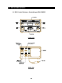
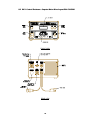
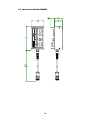
1
2200 Corporate Drive
Troy, OH 45373
Phone: (937) 440-0100
Fax: (937) 440-0277
WC 1
WELD SEQUENCE CONTROLLER
Operation / Installation Manual
Manual Part Number: C8M5002
Date: July 9, 2002
Revised: July 24, 2003
July 24, 2003
Manual No. 430429-518
July 24, 2003
Manual No. 430429-518
TABLE OF CONTENTS
1.0
1.1
1.2
1.3
1.4
2.0
GENERAL DESCRIPTION ............................................................................................ 1
OVERVIEW ..........................................................................................................................................................1
CONTROL OUTPUTS ...........................................................................................................................................1
CONTROL INPUTS ...............................................................................................................................................1
CONTROL DISPLAY AND STATUS INDICATORS .....................................................................................................2
CONTROL INSTALLATION .......................................................................................... 3
2.1 ENCLOSURE INSTALLATION .................................................................................................................................3
2.2 STANDARD ENCLOSURE DIMENSIONS .................................................................................................................3
2.3 REMOTE CONTROL RECEPTACLE .......................................................................................................................4
3.0
3.1
3.2
3.3
3.4
3.5
4.0
4.1
4.2
4.3
4.4
4.5
4.6
5.0
5.1
5.2
5.3
5.4
6.0
6.1
6.2
6.3
6.4
6.5
6.6
6.7
6.8
6.9
7.0
WELD SEQUENCE EVENTS........................................................................................ 5
WELD SEQUENCE PARAMETERS........................................................................................................................5
PULSE WELD MODE PARAMETERS ....................................................................................................................5
WELD CYCLE EVENTS .......................................................................................................................................5
SPOT WELD MODE ............................................................................................................................................6
ARC ACTIVE TEST..............................................................................................................................................6
USER INTERFACE ........................................................................................................ 7
REMOTE CONTROL INTERFACE SPECIFICATION...................................................................................................7
REMOTE PENDANT INTERFACE ...........................................................................................................................7
OPTIONAL OPERATOR PENDANT.........................................................................................................................7
RS-232 SERIAL PORT ........................................................................................................................................7
AUTOMATED USER INTERFACE ...........................................................................................................................7
TYPICAL USER INTERFACE FOR AUTOMATED OPERATION ...................................................................................9
CONTROL SPECIFICATION....................................................................................... 10
ENCLOSURE SPECIFICATION ............................................................................................................................ 10
CONTROL CABLES AND CONNECTORS ............................................................................................................. 10
CONTROLS AND STATUS INDICATORS .............................................................................................................. 10
SYSTEM SPECIFICATIONS ................................................................................................................................ 11
OPERATIONAL DISPLAY AND PROGRAMMING ................................................... 12
STATIC WELD DISPLAY SCREENS .................................................................................................................... 12
STATIC DISPLAY SCREEN ERROR MESSAGES.................................................................................................. 13
MODIFYING WELD SCHEDULE AND SYSTEM PARAMETERS............................................................................... 13
WELD SCHEDULE PARAMETER MENUS ............................................................................................................ 14
PAW WELD SCHEDULE MENU SCREENS ........................................................................................................ 14
PAW WITH COLD WIRE FEED OPTION W ELD SCHEDULE MENU SCREENS...................................................... 15
GMAW OPTION WELD SCHEDULE MENU SCREENS........................................................................................ 16
SETUP PARAMETER MENUS............................................................................................................................. 17
SETUP PARAMETER MENU SCREENS............................................................................................................... 17
WC 1 OFF-LINE RS-232 TERMINAL PROTOCOL.................................................... 18
7.1 GENERAL DESCRIPTION................................................................................................................................... 18
7.2 TERMINAL PROTOCOL...................................................................................................................................... 18
7.3 TERMINAL COMMANDS..................................................................................................................................... 19
8.0
ENCLOSURE LAYOUTS............................................................................................. 22
8.1 WC 1 CONTROL ENCLOSURE - STANDARD LAYOUT P/N: C3A5003 ............................................................... 22
July 24, 2003
Manual No. 430429-518
8.2 WC 1 CONTROL ENCLOSURE - CAPSTAN MOTOR DRIVE LAYOUT P/N: C3A5004 .......................................... 23
8.3 OPERATOR PENDANT P/N: C3A5006 ............................................................................................................. 24
9.0
ENCLOSURE PARTS LISTS ...................................................................................... 25
9.1 WC 1 CONTROL ENCLOSURE - STANDARD LAYOUT P/N: C3A5003 ............................................................... 25
9.2 WC 1 CONTROL ENCLOSURE – CAPSTAN MOTOR DRIVE LAYOUT P/N: C3A5004 ......................................... 27
9.3 WC 1 PENDANT ENCLOSURE P/N: C3A5006 ................................................................................................ 30
July 24, 2003
Manual No. 430429-518
1.0 GENERAL DESCRIPTION
1.1 Overview
The following is a brief description of the WC 1 Thermal Arc Weld Sequence Controller. The WC 1
controller is based on an embedded micro controller. The Controller provides two 0-10 VDC
programmable outputs, one is used to control the Thermal Arc Plasma Power source and the
second, controls a Cold Wire Feed Motor Drive Control. The Controller provides 32 user selectable
weld schedules.
1.2 Control Outputs
The controller has five solid-state isolated relay outputs. One output is configured as an arc start
signal to the Thermal Arc power source. The remaining four has the following default configuration:
•
CR1 - Ready – This output is asserted when the Controller is operating normally. It will
reset when the controller is in ESTOP or an Internal/External fault has occurred.
•
CR2 - Arc Active – This output is asserted after the arc is established. The signal is
generated from the Thermal Arc power source. The output is cleared if a loss of arc is
detected, internal Program fault, or the cycle start signal is reset.
•
CR3 - Cycle Complete – This output is asserted when the programmed weld cycle has
been completed. If a fault or loss of arc has occurred during the cycle the Cycle complete
will not be set.
•
CR4 - Cycle Active – This output is active during the complete weld cycle and will be
cleared at the end of all programmed events.
1.3 Control Inputs
The Controller provides nine 24 VDC Optically isolated inputs. Three inputs are dedicated for
ESTOP, Arc Active and Pilot Arc Active. The Arc Active and Pilot Arc Active inputs are connected
to the Thermal Arc power source. The ESTOP input may be internally set to the active state. The
remaining six inputs may be configured for remote schedule or program control. The nine inputs
have the following default configuration:
•
ESTOP – This input must be active. If the ESTOP is cleared the control performs an
emergency stop and halts the weld cycle and resets all outputs. When asserted the
controller performs a power up sequence.
•
ARC ACTIVE – When asserted the controller will initiate the Start Timer Event. If the weld
is not initiated within 2 seconds of cycle start the control will terminate the weld cycle and
clear the Ready Output. The user must clear the Cycle start input to reset the Ready
output.
•
PILOT ARC ACTIVE – This input must be asserted to set the Ready output and to allow
the controller to perform a weld cycle. An external jumper can force this input.
•
INP 1 – SCHED 0 – User definable spare input. Under remote schedule mode this input
can be used for weld schedule selection (Bit 0).
•
INP 2 – SCHED 1 - User definable spare input. Under remote schedule mode this input
can be used for weld schedule selection (Bit 1).
1
•
INP 3 – SCHED 2/ PARAMETER SELECT - User definable spare input. Under Remote
Schedule Mode this input can be used for weld schedule selection (Bit 2). Under Remote
Control Mode this input is used to select the parameter to Increase/Decrease. When
Cleared the Current is selected. When Asserted the Wire Feed speed parameter is
selected. This option is only active when the optional wire drive and when the Remote
control mode is enabled.
•
INP 4 – SCHED 3/ INCREASE PARAMETER – User definable spare input. Under Remote
Schedule Mode this input can be used for weld schedule selection (Bit 3). Under Remote
Control Mode activating this input will increment the selected parameter as specified by
INP3. The maximum increase level can be user defined for each weld schedule.
•
INP 5 – SCHED 4/ DECREASE PARAMETER - User definable spare input. Under
Remote Schedule Mode this input can be used for weld schedule selection (Bit 4). Under
Remote Control Mode asserting this input will decrease the selected parameter as
specified by INP3. The minimum decrease level can be user defined for each schedule.
•
INP 6 - CYCLE START – This Input, when asserted, will start a weld cycle and must be
active during the complete weld cycle. If the input is reset the cycle will be terminated. If
the Spot Weld mode is enabled, the weld cycle will be terminated by the user defined weld
time. The Cycle start input must be reset before the next weld cycle can be initiated.
1.4 Control Display and Status Indicators
The controller has a 2-line 16-character Alpha Numeric LCD display which is used to program the
weld schedule data and to configure the control options. Three push button switches are used to
select the desired parameters and to increment or decrement the values. A Program/Run key lock
switch is provided to prevent unauthorized access to the WC 1 weld schedule and system
configuration. Eight Status LEDs are used to indicate the weld sequence events and selected
modes. The Program LED is illuminated when the WC 1 is in weld sequence mode. The Pulse
LED is illuminated when the Pulse Weld function is active. During a weld cycle the status LEDs will
be illuminated to indicate weld event sequence being executed. A RS-232-C serial port is provided
and allows the user to program all of the WC 1 schedules and features off-line.
2
2.0 CONTROL INSTALLATION
2.1 Enclosure Installation
Install the Enclosure in a convenient location that allows easy operator access to the front control
panel. Allow a minimum clearance of 6” (152mm) from the rear of the enclosure to allow access for
the external cable connections. To permanently mount the enclosure remove the four rubber feet
and mount the enclosure using blind-hole fasteners located on the bottom of the enclosure. Connect
the Power cable to a suitable source of AC power. Connect the Power supply remote cable to the
“POWER SUPPLY CONTROL” receptacle. Connect the optional operator pendant control cable to
the “REMOTE PENDANT” receptacle.
2.2 Standard Enclosure Dimensions
3
2.3 Remote Control Receptacle
The optional remote control receptacle provides a basic operational control interface to the WC 1
controller. The following is the pin-out and control function for the 9 pin receptacle.
PIN
DESCRIPTION
1
+24 vdc @ 100 ma. Power Output
2
ESTOP – 24 VDC input
3
CYCLE START – 24 VDC input
4
INC – 24 VDC Input. Increase the current during the weld cycle
5
DEC – 24 VDC Input. Decreases the current during the weld cycle
6
CYCLE ON - 24 VDC Active low sinking (Pull-Down) output
7
CYCLE COMPLETE – 24 VDC Active Low sinking (Pull-Down) output
8
EARTH GROUND
9
READY – 24 vdc Active Low sinking (Pull-Down) output
Table 1 - WC 1 Remote Control Receptacle Pin-Out
4
3.0 WELD SEQUENCE EVENTS
3.1 Weld Sequence Parameters
The WC 1 Plasma Weld Sequence Controller provides the following user defined parameters:
•
START CURRENT – The value of current to be used during the start time event.
•
START TIME – The amount of time to hold the start current before beginning the Ramp Up
Event.
•
RAMP UP TIME – The time required to ramp from the start current to the run current.
•
RUN CURRENT – The value of current to be used during the Run time of the weld cycle.
•
WELD TIME – The user defined spot weld time when enabled.
•
% TAPER CURRENT - The % of Run current used as the end current level for the taper
time and the start of the Ramp Down Event.
•
TAPER TIME – The amount of time required for the Current Taper Event.
•
RAMP DOWN TIME – The amount of time required to ramp from the % Taper current
value to the End current value prior to the End Current Event.
•
END CURRENT - The end cycle current level to be used during the End Cycle Time.
•
END TIME – The amount of time required for the end weld event.
3.2 Pulse Weld Mode Parameters
If the Pulse mode is enabled the following parameters will be used to define the pulse conditions:
•
PULSE ON TIME – Specifies the Pulse On time period when the Pulse mode is enabled.
•
PULSE OFF TIME – Specifies the Pulse Off time period when the Pulse mode is enabled.
•
% PULSE CURRENT – Specifies the percent of the Run current that will be used during
the Pulse Off time period.
3.3 Weld Cycle Events
The Weld cycle is initiated by asserting the Cycle Start Input. The controller will monitor the Arc
Active input and will assert the Active output when active. The controller will set the Thermal Arc
Power source to the value specified by the Start Current Parameter. After the Start time has expired
the Current output would be ramped to the Run current value over the Ramp Up time specified. At
the end of the Ramp Time the Run current value will be active. If the Pulse mode is enabled the
Pulse On time will be used to specify the time at Peak Current. The Pulse Off Time and Percent
Current will be used to define the background pulse condition. If the Spot Time is Disabled the
controller will continue to operate in the Run Event. When the Cycle Start is reset the controller will
begin the Taper Time and ramp the Run current to the level specified by the Percent Taper
parameter. If the Pulse mode is enabled the pulsing will start during the Ramp Up event and will
continue through the ramp down event. At the end of the ramp down time the controller will set the
End Current value and will hold this value for the time specified by the End Time parameter. The
5
Cycle Complete will be asserted at the end of the weld cycle when the Arc Active Signal has been
cleared by the power source. The Cycle complete will remain set until the next Cycle start is
asserted. To disable any weld event set the associated time to zero.
3.4 Spot Weld Mode
If the Spot Time mode is enabled the Taper Event will be started at the end of the Spot Weld Time.
Then the normal end events will be executed. In this mode the Cycle Start must be active until the
end of the weld cycle. The Controller will not reset the weld event until the Cycle input has been
cleared. The Cycle complete will be asserted when the Arc Active Signal is cleared. The Cycle
Complete Output will be cleared when the Cycle start is cleared.
3.5 Arc Active Test
If the Arc Active input from the power source is not active within the user specified start time after
the cycle start has been asserted, the controller will clear the weld event and reset the Ready
Output. The Cycle Start input must be cycled off before the Ready Output can be asserted. If the
Cycle start input is cleared prior to the weld event the controller will terminate the arc and will not set
the Cycle Complete output.
6
4.0 USER INTERFACE
4.1 Remote Control Interface Specification
The WC 1 Controller provides a remote control interface that allows the user to connect an external
PLC or robotic control to the WC 1. The interface provides remote schedule select, cycle start and
operational status indication. The WC 1 inputs are configured to operate from a 24 VDC power
source. The inputs can be configured for Pull-Up (Sourcing) or Pull Down (Sinking). A 24 VDC @
200MA isolated power supply (TB5) is provided to allow dry contact closures to activate the WC 1
inputs. All Relay Outputs are opto-isolated solid-state relays and will switch AC/DC loads up to 120
VAC at 1 amp.
4.2 Remote Pendant Interface
A 9 pin CPC circular connector is provided to allow the use of a manual operator control pendant.
The Optional Operator Pendant is designed to connect to this Operator Control connector and will
perform the following Control functions:
•
ESTOP – Palm button provides emergency stop input to the weld control.
•
CYCLE ON – Toggle switch to start and stop a weld cycle.
•
INC CURRENT – Pushbutton switch used to increase the Run current during a weld cycle.
The control will provide user defined limits for current change.
•
DEC CURRENT – Pushbutton switch used to Decrease the Run current during a weld
cycle. The control will provide user defined limits for current change.
•
READY – Green LED Indicator.
•
CYCLE ON – Red LED Indicator.
•
CYCLE COMPLETE – Green LED Indicator.
4.3 Optional Operator Pendant
The Operator Control Pendant is a NEMA 1 rated clamshell enclosure with a 15 ft control cable and
Remote I/O plug. If the WC 1 controller is to be used in a robotic or PLC based application the
remote pendant option is disabled and the inputs must be reconfigured for the desired remote
PLC/Robotic control functions.
4.4 RS-232 Serial Port
All weld schedule programming can be performed off-line via a RS-232 serial port or using the
internal display and program buttons. The Internal display allows the user to program all of the WC 1
Plasma Weld sequence parameters and to configure the controller operational modes. It can also
be used to Save and Load internal weld schedules.
4.5 Automated User Interface
The WC 1 controller allows full remote control capabilities for use with PLC or robotic controllers.
The control provides a 24-vdc interface that allows the users to select weld schedules and to
start/Stop the welding sequence. The controller provides a simple hand shaking output that allows
7
the Host controller to validate the weld sequence. Four relay outputs provide the following
information to the host controller:
•
CR1 - Ready – This output is asserted when the Controller is operating normally. It will
reset when the controller is in ESTOP or an Internal/External fault has occurred.
•
CR2 - Arc Active – This output is asserted after the arc is established. The signal is
generated from the Thermal Arc power source. The output is cleared if a loss of arc is
detected, internal Program fault, or the cycle start signal is reset.
•
CR3 - Cycle Complete – This output is asserted when the programmed weld cycle has
been completed. If a fault or loss of arc has occurred during the cycle the Cycle complete
will not be set.
•
CR4 - Cycle Active – This output is active during the complete weld cycle and will be
cleared at the end of all programmed events.
The interface also provides a ESTOP circuit and six 24 vdc inputs that provide the following control
functions:
•
ESTOP – This input must be active. If the ESTOP is cleared the control performs an
emergency stop and halts the weld cycle and resets all outputs. When asserted the
controller performs a power up sequence.
•
INP 1 – SCHED 0 – User definable spare input. Under remote schedule mode this input
can be used for weld schedule selection (Bit 0).
•
INP 2 – SCHED 1 - User definable spare input. Under remote schedule mode this input
can be used for weld schedule selection (Bit 1).
•
INP 3 – SCHED 2/ PARAMETER SELECT - User definable spare input. Under Remote
Schedule Mode this input can be used for weld schedule selection (Bit 2). Under Remote
Control Mode this input is used to select the parameter to Increase/Decrease. When
Cleared the Current is selected. When Asserted the Wire Feed speed parameter is
selected. This option is only active when the optional wire drive and when the Remote
control mode is enabled.
•
INP 4 – SCHED 3/ INCREASE PARAMETER – User definable spare input. Under Remote
Schedule Mode this input can be used for weld schedule selection (Bit 3). Under Remote
Control Mode activating this input will increment the selected parameter as specified by
INP3.
•
INP 5 – SCHED 4/ DECREASE PARAMETER - User definable spare input. Under
Remote Schedule Mode this input can be used for weld schedule selection (Bit 4). Under
Remote Control Mode asserting this input will decrease the selected parameter as
specified by INP3.
•
INP 6 - CYCLE START – This Input, when asserted, will start a weld cycle and must be
active during the complete weld cycle. If the input is reset the cycle will be terminated. If
the Spot Weld mode is enabled, the weld cycle will be terminated by the user defined weld
time. The Cycle start input must be reset before the next weld cycle can be initiated.
To use the Remote control interface the user must connect the PLC or Robot I/O to the internal
terminal blocks provide on the Main controller PCB assembly. The Remote Control function must
be enabled via the RS-232 serial port terminal command. See Section 7 for additional information.
8
4.6 Typical User Interface for Automated Operation
1
2
4
3
ULTIMA-150 ENCLOUSER
WC 1 ENCLOSURE
LOGIC BD
TB1
1
2
3
4
5
6
7
8
9
10
11
12
13
14
15
16
17
18
19
20
21
22
23
24
D
TB7
"WELD REMOTE"
1
2
3
4
5
6
7
8
D
DAC 1
DAC 2
ANL COM
W_ARC ACTIVE
W_READY
WCOM
WC-A
WC-B
TB3
"I/O POWER"
5
4
3
2
1
I/O COM
I/O COM
ESTOP+
+24 I/O
+24 I/O
CONNECTION TO ULTIMA-150 FOR AUTOMATED APPLICATIONS
C
C
CR6
CYCLE ON
CR5
SCHEDULE SELECT DECODE
SCHED4
WC 1 CONTROL PCB ASS'Y
SCHED
CR1
CR2
CR3
CR4
CR5
SCHED3
1
2
0
1
0
0
0
0
0
0
0
0
CR3
3
4
0
1
1
1
0
0
0
0
0
0
5
6
0
1
0
0
1
1
0
0
0
0
7
0
1
1
0
0
8
9
1
0
1
0
1
0
0
1
0
0
10
11
1
0
0
1
0
0
1
1
0
0
12
13
1
0
1
0
0
1
1
1
0
0
14
15
1
0
0
1
1
1
1
1
0
0
16
17
1
0
1
0
1
0
1
0
0
1
18
19
1
0
0
1
0
0
0
0
1
1
20
21
1
0
1
0
0
1
0
0
1
1
22
23
1
0
0
1
1
1
0
0
1
1
24
25
1
0
1
0
1
0
0
1
1
1
26
27
1
0
0
1
0
0
1
1
1
1
28
29
1
0
1
0
0
1
1
1
1
1
30
31
32
1
0
1
0
1
1
1
1
1
1
1
1
1
1
1
CR4
TB5
"I/O"
SCHED2
12
11
10
9
8
7
6
5
4
3
2
1
CR2
SCHED1
CR1
SCHED0
OUTPUT COMMON
CYCLE ACTIVE OUTPUT
CYCLE COMPLETE OUPUT
ARC ON OUTPUT
READY OUTPUT
IN COM
START
SCHED 4
SCHED 3
SCHED 2
SCHED 1
TYPICAL INPUT
5 - 24 VDC INPUT
2.7K
SCHED 0
OUT COM
ACTIVE
COMPLETE
ARC ON
READY
115 VAC/DC
@ 1AMP N.O.
TYPICAL OUTPUT
B
TB3
"I/O POWER"
5
4
3
2
1
CMR
SYSTEM ESTOP
I/O COM
I/O COM
ESTOP+
+24 I/O
+24 I/O
READY
CYCLE START
ACTIVE
COMPLETE
ARC ON
TYPICAL WELD CYCLE I/O TIMING
B
NOTES:
1. WHEN REMOTE SCHEDULE OPTION IS ENABLED CR1-CR5 SELECT THE WELD SCHEDULE BASED ON DECODE TABLE
2. WHEN REMOTE SCHEDULE OPTION IS DISABLE CR1-CR2 HAVE NO EFFECT AND CR3-CR5 CONTROL THE FOLLOWING FUNCTIONS:
CYCLE ON (CR6 = ON)
CYCLE OFF (CR6=OFF)
CR3 - SELECT AMP/WIRE (OFF = AMP)
CR4 - DECREASE RUNAMP/WIRE
CR3 - SELECT AMP/WIRE (OFF = AMP)
CR4 - JOG WIRE IN REVERSE DIRECTION
CR5 - INCREASE RUN AMP/WIRE
CR5 - JOG WIRE IN FORWARD DIRECTION
A
A
PLC/ROBOTIC WELD CONTROL INTERFACE
1
2
3
9
4
5.0 CONTROL SPECIFICATION
5.1 Enclosure Specification
The Weld Sequence Controller consists of a Main CPU P.C. board, Display/Keypad P.C. Board and
a 2-line 16-character LCD display. All external user connections are made via seven P.C. Board
mounted screw terminal blocks. The controller is designed to allow the addition of a Capstan PWM
motor drive controller, which can be used to control the Capstan Cold Wire Feed system. The PWM
module is installed in the rear of the control enclosure. There will also be provisions made to install
the necessary Power supply components inside the enclosure. This consists of a transformer, and
power supply assembly and wiring harness. This allows easy installation of the wire drive controller
option. The sheet metal enclosure is a clamshell design and conforms to a NEMA 1 rating.
5.2 Control Cables and Connectors
The enclosure has a single 15 ft rigid mounted power source control cable to interface to the
Thermal Arc power source. A rigid mounted 6 ft 115 VAC molded cable is used to provide power to
the controller. Provisions are made to allow a rigid mounted Capstan™ drive motor cable and PWM
Motor drive control Heat sink assembly to be installed. This option allows the WC 1 to program and
control a Capstan™ cold wire feed drive. A 9-pin CPC Circular connector is provided to allow
interconnection of an optional operator control pendant. A RS-232-C Female DB-9 connector is
provided to allow off-line programming of the weld schedules.
5.3 Controls and Status Indicators
The following is a summary of the front panel controls and status indicators:
•
POWER SWITCH – Illuminated rocker switch applies power to the controller.
•
PROGRAM/RUN – Key Lock switch that enables the WC 1 program mode. When the
switch is in the program position the user has full access to the controller weld schedules
and configuration parameters. When set in the run position the operator can only change
the parameters enabled within a specified high/low limit.
•
SELECT – This momentary pushbutton switch is used to select the WC 1 parameter to be
modified. Editing of the selected parameter is only allowed when the key switch is in the
program position.
•
INC /DEC – These two momentary push button are used to increase or decrease the
selected parameter. Editing of the selected parameter is only allowed when the key switch
is in the program position.
•
START LED – Indicates when the weld event is in the start sequence.
•
RAMP UP LED – Indicates when the weld event is in the Ramp Up sequence.
•
RUN LED – Indicates when the weld event is in the Run sequence.
•
TAPER LED – Indicates when the weld event is in the Taper sequence.
•
RAMP DOWN LED – Indicates when the weld event is in the Ramp down sequence.
•
END LED – Indicates when the weld event is in the End sequence.
10
•
PROGRAM LED - Indicates when the WC 1 weld schedule program is active.
•
PULSE LED - Indicates when the pulse mode is active.
5.4 System Specifications
The following are the system specifications:
Plasma Weld Sequence Controller:
Dimensions:
Power Input:
Operating Temp:
Relay Outputs:
Switch Inputs:
Analog Outputs:
Encoder Input:
5.0"H x 9.0"W x 11"L (102mm x 165mm x 280mm)
110 - 240 vac 50/60 hz @ 0.2kw
-10 ° F to +140° F (-23°C to +60°C)
115 VAC/VDC 1 amps normally open contact
5 - 24 vdc @ 1.0 - 8.0 ma.
10 vdc precision reference output. 10 bit resolution (10 mv
resolution) Maximum output current 10 ma. Output is short circuit
protected.
Pulse accumulator input 5.0 vdc TTL level with 4.7K pull-up.
Maximum input frequency 15 khz.
11
6.0 OPERATIONAL DISPLAY AND PROGRAMMING
6.1 Static Weld Display Screens
The WC 1 controller provides a 2-line 16-character display and four control switches that allow the
user to program the weld variables and to select the various weld schedules. When not altering
parameters the display will indicate current status of the controller. The first line of the display will
show the product type message. The Second line will show the current set point value for the
analog outputs that are enabled. The values displayed are the final values for each weld cycle
event. The values are not varied during the ramp or pulse event but are set to the end or peak
values. The actual values displayed are the result of the control mode and options installed. The
following are the various Weld active Display screens that will be displayed, during a weld cycle, on
the second line of the display.
DISPLAY
AMP=###
AMP=### WFS=###
VOL=##.# WFS=###
MESSAGE DESCRIPTION
This screen will be displayed for PAW and GTAW mode when the wire drive
option is not installed. (Where: ### is the current set point value)
This screen will be displayed for PAW and GTAW mode when the wire drive
option is installed. (Where: ### is The current set point value)
This screen will be displayed for GMAW mode. (Where: ### is The current set
point value)
Table 1 - Static Screen Display Message
12
6.2 Static Display Screen Error Messages
During the weld cycle the WC 1 controller performs diagnostic checks on the system and control
inputs. If an error occurs the WC 1 will display the error message on the second line of the static
message screen. The following is a summary of the error messages:
DISPLAY
SCHED 1
READY!
PGM EVENT
ERROR!
ERROR MESSAGE DESCRIPTION
No Errors. Normal static message screen displays active schedule number.
POWER NOT
READY!
Power supply not ready error indicates the Power supply ready input is not
asserted. This error will occur when the Cycle start is asserted and the Ready
input is not active. Error is reset when Cycle start is cleared.
The Start parameters are being ramped to the run level and the Ramp time delay
is active.
Schedule Fault Error indicates the active weld schedule has an invalid
parameter. This error will occur when an out-of-range parameter is detected
during a weld cycle. Error is automatically reset when Cycle start is cleared.
ESTOP message indicates that the WC 1 controller has been forced into a
Emergency stop condition by clearing the WC1 ESTOP input. When the ESTOP
mode is active all WC 1 outputs and weld events are cleared. The only recovery
is to assert the ESTOP input signal.
ARC ACTIVE FAIL!
SCHEDULE
FAULT!
**SYSTEM
ESTOP**
Program Event Error indicates the active weld schedule has an invalid event
enabled. Error is automatically reset when Cycle start is cleared.
Table 2 - Displayed Error Messages
6.3 Modifying Weld Schedule and System Parameters
The WC 1 Control provides two methods for programming a weld schedule. The first method is to
use a PC and the RS-232 serial port to program the schedules off line. Refer to Section 7.0 for
additional information on serial off-line programming. To create, modify or load a schedule set the
front panel key-lock switch to the “PROGRAM” position. The WC 1 will display the “WELD
PARAMETER" menu option. Select this menu by pressing the “SEL” button. To change the Control
configuration parameters press the “INC” or “DEC” button. The WC 1 will display the “CONFIG
PARAMETER” menu option. To select a specific menu option, press the “SEL” button. After
selecting a menu option the WC 1 will display the menu items and their current values on the
display. To move forward through the menu items press the “INC” button. To move back to the
previous menu item, press the “DEC” button. When moving through the menu items the WC 1 will
display the current value for each of the items selected. To change any selected item press the
“SELECT” button. A Blinking cursor will be displayed. To increase the displayed value, press the
“INC” button. To decrease the value, press the “DEC” button. To exit the edit routine press the
“SELECT” button. The Blinking cursor will be cleared from the display. Move to the next item by
pressing the “INC” or “DEC” buttons. To exit the schedule, edit routine turn the key-lock switch to the
“RUN” position. If a value has been modified, by pressing the “SELECT” button, the display will
show a “SAVING SCHEDULE” prompt indicating that the changes have been saved to the WC 1
nonvolatile Memory. The Display will then return to the normal Static display messages.
13
6.4 Weld Schedule Parameter Menus
The WC 1 controller can support several different options. Depending on which options are
installed three different menus will be displayed. Each menu is specific to the available functions
and features that are installed. Placing the key-lock switch to the “RUN” position enables the edit
function. One of the following Program menus will be displayed.
6.5 PAW Weld Schedule Menu Screens
DISPLAY
PARAMETER DESCRIPTION
RANGE
UNITS
START CURRENT
AMP =
START DELAY
TIME =
Weld cycle start current level.
1 - 500
Amps
The time period at the Start current level.
0 – 60.00
Sec.
RAMP UP TIME
TIME =
RUN TIME CURRENT
AMP =
SPOT WELD TIME
TIME =
The time that will be used to ramp the welding
current from the start to the run value.
The current level that will be used during the run
time portion of the weld cycle.
The time period at the run current. If set the weld
sequence will automatically terminate at the end
of this time. If zero the user must clear the Cycle
start signal to terminate the weld cycle.
The percent of run current that will be reached at
the end of the taper event.
The time period to perform the current taper
event.
The time period used to ramp the current from the
Taper % level to the end current level.
The current level that will be used during the end
time period.
The time period at the end current level.
0 – 60.00
Sec.
1- 500
Amps
0 – 650.00
Sec.
1 – 100
%
0 – 600.00
Sec.
0 – 60.00
Sec.
1 - 500
Amps
0 – 60.00
Sec.
Enable/Disable the pulse weld mode. If enabled
the pulse mode will be active from the start of the
ramp up event to the end of the ramp down
event.
The time period at the run current level when the
pulse mode is active.
The time period at the background current level
when the pulse mode is active.
The percent of the peak current value that is used
for the background current level.
Select the user defined weld schedule and read
the schedule from weld memory into the active
weld schedule parameters.
Write the current active weld schedule to the
specified schedule number in the weld memory.
0–1
Yes/No
.001-60.000
Sec.
0.001-60.000
Sec.
1-100
%
PERCENT TAPER
TAPER % =
TAPER DELAY TIME
TIME =
RAMP DOWN TIME
TIME =
END CURRENT
AMPS =
END DELAY TIME
TIME =
PULSE MODE
MODE =
PULSE ON TIME
TIME =
PULSE OFF TIME
TIME =
% BACKGROUND AMP
AMP % =
SELECT SCHEDULE
SCHED =
SAVE SCHEDULE
SCHED =
1 – 32
1 - 32
Table 3 - Weld Schedule Menu for PAW Welding Mode
14
6.6 PAW With Cold Wire Feed Option Weld Schedule Menu Screens
DISPLAY
PARAMETER DESCRIPTION
RANGE
UNITS
START CURRENT
AMP =
START WIRE SPEED
SPEED =
Weld cycle start current level.
1 - 500
Amps
The wire feed speed to be used during the start
time period. To disable set the speed to 0.
0-1000
Ipm
START DELAY
TIME =
The time period at the Start current level.
0 – 60.00
Sec.
RAMP UP TIME
TIME =
RUN TIME CURRENT
AMP =
RUN WIRE SPEED
SPEED =
SPOT WELD TIME
TIME =
The time that will be used to ramp the welding
current from the start to the run value.
The current level that will be used during the run
time portion of the weld cycle.
The wire feed speed to be used during the Run
time period. To disable set the speed to 0.
The time period at the run current. If set the weld
sequence will automatically terminate at the end
of this time. If zero the user must clear the Cycle
start signal to terminate the weld cycle.
The percent of run current that will be reached at
the end of the taper event.
The time period to perform the current taper
event.
The time period used to ramp the current from the
Taper % level to the end current level.
The current level that will be used during the end
time period.
The wire feed speed to be used during the end
time period. To disable set the speed to 0.
The time period at the end current level.
0 – 60.00
Sec.
1- 500
Amps
0-1000
Ipm
0 – 650.00
Sec.
1 – 100
%
0 – 600.00
Sec.
0 – 60.00
Sec.
1 - 500
Amps
0-1000
Ipm
0 – 60.00
Sec.
The time period to reverse the wire feeder and
back the wire out of the arc. The Wire speed is
the end wire value.
Enable/Disable the pulse weld mode. If enabled
the pulse mode will be active from the start of the
ramp up event to the end of the ramp down
event.
The time period at the run current level when the
pulse mode is active.
The time period at the background current level
when the pulse mode is active.
The wire drive speed that is used while not
welding.
The percent of the peak current value that is used
for the background current level.
Select the user defined weld schedule and read
the schedule from weld memory into the active
weld schedule parameters.
Write the current active weld schedule to the
specified schedule number in the weld memory.
0 - 60.00
Sec.
0–1
Yes/No
.001-60.000
Sec.
0.001-60.000
Sec.
0 – 1000
Ipm
1-100
%
PERCENT TAPER
TAPER % =
TAPER DELAY TIME
TIME =
RAMP DOWN TIME
TIME =
END CURRENT
AMPS =
END WIRE SPEED
SPEED =
END DELAY TIME
TIME =
REV WIRE DELAY
TIME =
PULSE MODE
MODE =
PULSE ON TIME
TIME =
PULSE OFF TIME
TIME =
JOG WIRE SPEED
SPEED =
% BACKGROUND AMP
AMP % =
SELECT SCHEDULE
SCHED =
SAVE SCHEDULE
SCHED =
1 – 32
1 - 32
Table 4 - Weld Schedule Menu for PAW with Cold Wire Feed option enabled
15
6.7 GMAW Option Weld Schedule Menu Screens
DISPLAY
PARAMETER DESCRIPTION
RANGE
UNITS
PREPURGE TIME
TIME =
START VOLTAGE
VOLTS =
START WIRE SPEED
SPEED =
Pre purge gas flow time period.
0 - 60.00
Sec.
Weld cycle start voltage level.
10.0- 50.0
Volts
The wire feed speed to be used during the start time
period.
0-1000
Ipm
START DELAY
TIME =
The time period at the Start level.
0 – 60.00
Sec.
RAMP UP TIME
TIME =
RUN TIME VOLTAGE
AMP =
RUN WIRE SPEED
SPEED =
SPOT WELD TIME
TIME =
The time that will be used to ramp the parameters
from the start to the run value.
The voltage level that will be used during the run time
portion of the weld cycle.
The wire feed speed to be used during the Run time
period.
The time period at the run level. If set the weld
sequence will automatically terminate at the end of this
time. If zero the user must clear the Cycle start signal
to terminate the weld cycle.
The percent of run wire speed that will be reached at
the end of the taper event.
The time period to perform the taper event.
0 – 60.00
Sec.
10.0- 50.0
Volts
0-1000
Ipm
0 – 650.00
Sec.
1 – 100
%
0 – 600.00
Sec.
The time period used to ramp from the Taper % level
to the end level.
The voltage level that will be used during the end time
period.
The wire feed speed to be used during the end time
period.
The time period at the end level.
0 – 60.00
Sec.
10.0– 50.0
Volts
0-1000
Ipm
0 – 60.00
Sec.
0 - 60.00
Sec.
PERCENT TAPER
TAPER % =
TAPER DELAY TIME
TIME =
RAMP DOWN TIME
TIME =
END VOLTAGE
VOLTS =
END WIRE SPEED
SPEED =
END DELAY TIME
TIME =
REV WIRE DELAY
TIME =
BURN BACK TIME
TIME =
POST PURGE TIME
TIME =
JOG WIRE SPEED
SPEED =
SELECT SCHEDULE
SCHED =
SAVE SCHEDULE
SCHED =
The time period to reverse the wire feeder and back
the wire out of the arc. The Wire speed is the end wire
value.
The time period, which will be used to hold the weld
contactor on after halting the wire feed motor.
The Post Gas flow time period.
.01 - 6.00
Sec.
.01-60.00
Sec.
The wire drive speed that is used while not welding.
0 – 1000
Ipm
Select the user defined weld schedule and read the
schedule from weld memory into the active weld
schedule parameters.
Write the current active weld schedule to the specified
schedule number in the weld memory.
1 – 32
1 - 32
Table 5 - Weld Schedule Menu for GMAW option enabled
16
6.8 Setup Parameter Menus
The WC 1 controller can support several different options. The setup Parameter menu allows the
user to configure various setup control parameters and options. Depending on which options are
enabled different Weld parameter menus will be displayed. The user can also specify the current
range for a power supply and enable remote I/O weld schedule selections.
6.9 Setup Parameter Menu Screens
DISPLAY
PARAMETER DESCRIPTION
RANGE
REMOTE SCHEDULE
SELECT =
Enable remote weld schedule option. When “ON” the
user supplied I/O SCHED 0 - 4 inputs (TB5-6- TB5-10) will
specify the desired weld schedule. Refer to Section 4.5
for additional information
ON/OFF
GTAW CONTROL
MODE =
Enables the GTAW process mode and weld parameter
menus
ON/OFF
GMAW CONTROL
MODE =
MAX CURRENT
AMP =
Enables the WC 1 control for the GMAW (MIG/MAG)
process mode and weld parameter menu
The Maximum current level that the power source can
provide. This value is used to scale the WC 1 analog
output.
The Minimum current level that the power source can
provide. This value is used to scale the WC 1 analog
output.
ON/OFF
MIN CURRENT
AMP =
Table 6- Setup Parameter menu functions
17
UNITS
1- 500
Amps
1- 500
Amps
7.0 WC 1 OFF-LINE RS-232 TERMINAL PROTOCOL
7.1 General Description
The RS-232 Terminal mode can be used to off-line program the user configurable parameters and
operating modes. The protocol is a simple ASCII command string that allows the user to upload or
download the various data. The user can use any terminal program to perform the programming
function. All program command functions are case sensitive. The serial port is configured for the
following data format:
•
Baud Rate: 19.2K, Full Duplex
•
Word Length: 8 Data Bits, One Stop and no parity
•
Hand Shaking: None
7.2 Terminal Protocol
The protocol consists of a command string and optional data bytes. The command string is an
alpha character and an option number followed by a "=" or "?", followed by optional data and
terminated with an ASCII "cr" (0dh). The "=" will indicate that data is being sent to the selected
parameter by the host controller. The "?" will indicate a request for data from the WC 1 to the host
controller. If the host is sending data to the WC 1 the data will be placed after the "=" character and
will be an ASCII string terminated with an ASCII "cr" (0dh). The following is an example of reading a
parameter value from the WC 1:
From Host type:
Response from WC 1:
V1? (cr)
##
Where: ## is the current value for the parameter and (cr) is the
enter key
The following is an example of how to modify a value in the WC 1 using the terminal commands:
From Host type:
V1=#### (cr)
Where: ## is the new value for the parameter and (cr) is the enter
key
18
7.3 Terminal Commands
The following is a summary of the Terminal Commands supported by the WC 1:
COMMAND
PARAMETER DESCRIPTION
RANGE
UNITS
V1
Prepurge time
0-650.00
.01Sec.
V2
Arc start current
0-500
Amps
V3
Arc Start Wire feed speed
0-650
Ipm
V4
Arc Start delay time
0-650.00
.01 Sec.
V5
V6
V7
V8
V9
V10
V11
V12
V13
V14
V15
V16
V17
V18
V19
V20
V21
Ramp up Delay time
Run time current (Pulse Peak current)
Run Time wire feed speed
Spot Weld Time (If Time=0 then Manual control)
Percent Taper current
Taper current delay time
Ramp down delay time
End current value
End wire feed speed
End delay time
Reverse wire speed time delay
Wire burn back delay time
Post gas flow time delay
Pulse current on time
Pulse current off time
Percent back ground current
Jog wire feed speed
0-650.00
0-650.00
0-650
0-650.00
0-100
0-650.00
0-650.00
0-500
0-650
0-650.00
0-650.00
0-650.00
0-650.00
.001 – 65.000
.001 – 65.000
0-100
0-650
.01 Sec
Amps
Ipm
.01 Sec.
%
.01 Sec.
.01 Sec.
Amps
Ipm
.01 Sec.
Sec.
.01 Sec.
.01 Sec.
.001 Sec.
.001 Sec.
%
Ipm
Table 7 - Weld Process and Command Table
19
COMMAND
M1
M2
M3
M4
M5
M6
PARAMETER DESCRIPTION
Read Remote Inputs
BIT 0 – Schedule Bit 0 input TB5-6
BIT 1 – Schedule Bit 1 input TB5-7
BIT 2 – Schedule Bit 2 input TB5-8
BIT 3 – Schedule Bit 3 input TB5-9
BIT 4 – Schedule Bit 4 input TB5-10
BIT 5 – Power Supply Ready Input TB7-5
BIT 6 – Arc Active Input TB7-4
BIT 7 – Cycle Start Input TB5-11
Read/Write Remote Relay Outputs CR1-CR6
BIT 0 – CR1 Weld Contactor Output TB7-7 & TB7-8
BIT 1 – CR2 Control Ready Output TB5-1
BIT 2 – CR3 Arc Active Output TB5-2
BIT 3 – CR4 Weld Cycle Complete Output TB5-3
BIT 4 – CR5 Weld Cycle Active Output TB5-4
BIT 5 – CR6 Enable Wire Drive Output TB4-4
Read/Write System Configuration Parameters
BIT 0 – Enable Remote Schedule Select Function
BIT 1 – Enable Wire Feed control functions
BIT 2 – Enable GMAW weld mode functions
BIT 3 – Enable GTAW weld mode functions
Terminal Baud Rate control
0 = 76.8K Baud
1 = 38.4K Baud
2 = 19.2K Baud (Default)
3 = 9600 Baud
4 = 4800 Baud
5 = 2400 Baud
6 = 1200 Baud
Weld Control Error Code
0No Error
1Weld Sequence Program Fault
2Power Supply Not Ready Fault
3ARC fail during weld cycle
4Schedule Fault – Invalid Parameter Data
5ESTOP active
Set to “M6=251” and power cycle the WC1 will Clear Memory and
reload factory default parameters (Version 1.23 and higher).
Table 8 - System Configuration and Mode command table
20
RANGE
0-255
0-255
0-15
0-6
1-5
251
COMMAND
W1
W2
W3
W4
W5
PARAMETER DESCRIPTION
RANGE
Weld Schedule Mode Flag:
Bit 0 – Enable Pulse Weld Mode
Bit 1..7 – Not defined
Active Weld Schedule number
0-255
Active Weld Event number
0Cycle Off
1Cycle Start
2Pre Purge
3Start Time
4Ramp Up Time
5Run Time (Spot Weld Time if enabled)
6Taper Current time
7Ramp Down Time
8End Time
9Wire Reverse Time
10 Burn Back Time
11 Post Purge Time
Write current schedule to specified weld schedule number
Read specified weld schedule from memory to active schedule
0-11
1-32
1-32
1-32
Table 9 - Weld Mode Command Table
COMMAND
PARAMETER DESCRIPTION
RANGE
A1
Minimum Power supply current output (A1 = AMPmin) used for DAC 1
scaling.
Maximum Power supply current (A2=AMPmax) used for DAC 1 scaling
Where: (DAC 1 Gain = [4000/( AMPmax – AMPmin)])
Minimum Wire Feed speed (A3 = WIREmin) used for DAC 2 scaling
0-255
A2
A3
0-500
0-255
A4
Maximum Wire Feed Speed (A5=WIREmax) used for DAC 2 scaling
Where: (DAC 2 Gain = [4000/( Wiremax – WIREmin)])
0-900
A5
Actual Setpoint value for DAC 1
0-500
A6
Actual Set point value for DAC2
0-900
Table 10 - Analog Scaling Command Table
21
8.0 ENCLOSURE LAYOUTS
8.1 WC 1 Control Enclosure - Standard Layout P/N: C3A5003
FRONT VIEW
REAR VIEW
22
8.2 WC 1 Control Enclosure - Capstan Motor Drive Layout P/N: C3A5004
FRONT VIEW
REAR VIEW
23
ESTOP
READY
!
OFF
ON
CYCLE
ON
CYCLE
!
INC
DEC
CYCLE
COMPLETE
8.3 Operator Pendant P/N: C3A5006
24
9.0 ENCLOSURE PARTS LISTS
9.1 WC 1 Control Enclosure - Standard Layout P/N: C3A5003
ITEM
1
2
3
4
5
6
7
8
9
10
11
12
13
14
15
16
17
18
19
20
21
22
23
24
25
26
27
28
29
30
QTY
1
1
1
1
1
1
1
1
1
1
1
1
4
4
1
3
1
1
1
4
1
1
8
4
4
18
8
8
9
4
PART NO
C3A5003
C3E5004
C3E5005
C3E5010
C5A5003-WC
C5A5004-WC
S3A5031
S2M5087
C3W5002
C3W5003
C3W5004
C3W5005
X6S5050
X6S5056
X3S5078
X3S5125
X3S5127
X3Z5027
X3Z5006
X6Z5036
X6Z5089
X6Z5069
DESCRIPTION
WC 1 Control Enclosure
WC 1 Control Cover
WC 1 Control Front Overlay
WC 1 Control Cover Plate
Weld Control PCB Assembly
Universal Pendant PCB Assembly
2 x 16 LCD Display Assembly
2 x 16 LCD Display Lens
WC 1 Control Wire Harness
WC 1 Front Panel Wire Harness
WC 1 Power Cord
WC 1 Power Switch Wire Harness
Spacer, #2 x 7/16” Long Nylon HH Smith #9165
Spacer, #2-56 x ¾” Long Stainless Steel RAF #2061-256-SS
Switch, Power Rocker Cutler-Hammer #1600R11E
Switch, Black Pushbutton SPDT Idec #AB6M-M1-B
Switch, Keylock SPDT Idec #AS6M-2KT2PB
Kit, Screwlock Std. Female Amp #205817-3
Fitting, Black Pigtail Heyco #3240
Bumper, Black HH Smith #2135
Plug, Dome Hole Black 5/8" Heyco #2663
Plug, Dome Hole Black 7/8" Heyco #2703
#2 Internal Lock Washer
#2-56 Hex Nut
#2-56 X 1/4" Long Pan Head Screw
#6-32 X 1/4" Long Pan Head Screw w/ Internal Lock Washer
#6-32 X 1/2" Long Pan Head Screw
#6 Internal Lock Washer
#6-32 Hex Nut
#10-32 X 1/2" Long Pan Head Screw
25
26
9.2 WC 1 Control Enclosure – Capstan Motor Drive Layout P/N: C3A5004
ITEM
1
2
3
4
5
6
7
8
9
10
11
12
13
14
15
16
17
18
19
20
21
22
23
24
25
26
27
28
29
30
31
32
33
34
35
36
37
38
39
40
41
42
43
44
45
46
47
QTY
1
1
1
1
1
1
1
1
1
1
1
1
1
1
1
1
1
1
1
1
7
4
1
4
4
1
3
1
1
2
4
1
4
3”
A/R
8
4
4
4
18
8
8
9
4
4
1
1
PART NO
C3A5003
C3E5004
C3E5005
C5A5003-WC
C5A5004-WC
S3A5031
S2M5087
C3W5002
C3W5003
C3W5004
C3W5005
C3W5006
C3W5007
C3W5008
C3W5009
C3W5010
S2M5050
C5A5005
C5A5006-9CM
C5A5007
X6S5023
X6S5057
X3C5026
X6S5050
X6S5056
X3S5078
X3S5125
X3S5127
X3Z5027
X3Z5006
X6Z5036
X6Z5069
X5Z5007
DESCRIPTION
WC 1 Control Enclosure
WC 1 Control Cover
WC 1 Control Front Overlay
Weld Control PCB Assembly
Universal Pendant PCB Assembly
2 x 16 LCD Display Assembly
2 x 16 LCD Display Lens
WC 1 Control Wire Harness
WC 1 Front Panel Wire Harness
WC 1 Power Cord
WC 1 Power Switch Wire Harness
PWM Control Wire Harness
PWM AC Power Wire Harness
PWM DC Power Wire Harness
PWM Motor Drive Cable
PWM Toroidal Transformer
Microstep Heatsink
PWM Driver PCB Assembly
PWM 9CM CPU PCB Assembly
PWM Power Supply PCB Assembly
Spacer, #6-32 x 1/2” Long SS M-F RAF #4534-632-SS-0
Spacer, #6-32 x 1/4” Long SS M-F RAF #4530-632-SS-0
Fuse, 8 amp 3ag Littlefuse #313008
Spacer, #2 x 7/16” Long Nylon HH Smith #9165
Spacer, #2-56 x ¾” Long Stainless Steel RAF #2061-256-SS
Switch, Power Rocker Cutler-Hammer #1600R11E
Switch, Black Pushbutton SPDT Idec #AB6M-M1-B
Switch, Keylock SPDT Idec #AS6M-2KT2PB
Kit, Screwlock Std. Female Amp #205817-3
Fitting, Black Pigtail Heyco #3240
Bumper, Black HH Smith #2135
Plug, Dome Hole Black 7/8" Heyco #2703
Washer, Shoulder Thermalloy #7721-7PPS
Tape, Kapton 1” Wide
Compound, Thermal Thermalloy #249
#2 Internal Lock Washer
#2-56 Hex Nut
#2-56 X 1/4" Long Pan Head Screw
#4-40 x 1/4” Long Pan Head Screw
#6-32 X 1/4" Long Pan Head Screw w/ Internal Lock Washer
#6-32 X 1/2" Long Pan Head Screw
#6 Internal Lock Washer
#6-32 Hex Nut
#6-32 X 3/8" Long Socket Cap Head Screw
#10-32 X 1/2" Long Pan Head Screw
#10-32 X 7/8" Long Pan Head Screw
#10 External Lock Washer
27
28
29
9.3 WC 1 Pendant Enclosure P/N: C3A5006
ITEM
1
2
3
4
5
6
7
8
9
10
11
12
13
14
15
16
17
18
19
20
21
QTY
1
1
2
1
1
2
1
2
1
1
25’
1
9
1
4
3
2
2
2
4
4
PART NO
C3A5007
C3E5008
X3S5125
X3S5126
X3S5128
X5D5052
X5D5053
X6A5014
X3P5793
X3Z5006
X3W5097
X3P5142
X3P0303
X3Z5060
X6Z5090
X5R0051
DESCRIPTION
WC 1 Pendant Base
WC 1 Pendant Cover
Switch, Black Pushbutton SPDT Idec #AB6M-M1-B
Switch, Selector SPDT Idec #AS6M-2Y2P
Switch, Pushbutton Red SPDT Idec #AB6M-V1-R
LED, Green Imlec #LED-407G
LED, Red Imlec #LED-407R
Handle, Black 3” Center RAF #8047-440-A-24
Strip, Terminal 12 Circuit Molex #C1512-151
Fitting, Black Pigtail Heyco #3240
Cable, 8 Cond. 26awg Shielded Belden #1213A
Connector, Plug Housing 9 pin CPC Amp #206708-1
Socket, Crimp 20-24 Gauge Amp #66105-2
Clamp, Cable CPC Amp #206966-1
Bumper, Black Self-Adhesive HH Smith #2446-103
Resistor, 2.7K ohm 5% 1/2W #RL20S272G
#2-56 X 5/8" Long Pan Head Screw
#2 Internal Lock Washer
#2-56 Hex Nut
#4-40 X 1/4" Long Pan Head Screw w/ Internal Lock Washer
#6-32 X 1/4" Long Pan Head Screw w/ Internal Lock Washer
30
31