1
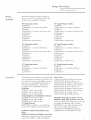
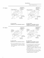
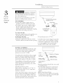
GE Monogram ®
Installation
Instructions
Stainless Steel
Professional Outdoor
Cooking
Centers
48" Natural g'a,s mode£:
ZGG48N42
ZGG48N3 I
ZGG48N40
ZGG48N30
48" Liquid Ih'@a)_e model, s:
ZGG48L42
ZGG48L31
ZGG48L40
ZGG48I_30
36" Natural
ZGG36N31
ZGG36N21
ZGG36N30
ZGG36N20
g'a,s modd, w
36" Liquid !'r@a_e
ZGG36L31
ZGG36L21
ZGG36L30
ZGG36120
modd, w
27" Natural g'a,s modd, s:
,
,c _
c
ZG(,21N21
Z(,(,2 IN20
27 _'Liquid Propa_e
,
,c _
c
Z(,G21121
,
,c_
c
ZG(,2
zL20
model, s:
Before wm begin--Read
these instructions completely and careflllly.
IMPORTANT: Sine these instructions for local inspector's use.
IMPORTANT: OBSERVE ALL GOVERNING
CODES AND ORDINANCES.
NOTE TO INSTALLER: Be sure to leave these instructions with tile Constm_er.
NOTE TO CONSUMER:
ftlture
reference.
Keep these instructions
If vou hme questions
concerning
tile
installation
of this product,
call tile GE
Answer Center ® (;onsumer
hfformation
Serxice at 800.626.2000,
7 days a week.
If vou receix ed a damaged
VOtl
should
FOR _r)UR
contact
VOIII"
Installation
of this cooking
center requires
basic mechanical
skills, Proper
installation
the responsibility
of the installer,
For Monogram
local serxice in your area
1-800-444-1845.
24 horn's a day
cooking
_dth your Use and Care Book for
center,
dealer.
For Monogram
1-888-880-3030.
serxice
For Monogram
1-800-626-2002.
Parts
in Canada,
and Accessories,
call
IF "_g)/_5SMELL GAS:
SAFETY:
• Slmt off gas to appliance.
• Extinguish any open flame.
• Open lid.
• If odor continues, immediately
gas supplier.
Do not use cooking
center in a space where
gasoline
or other liquids hming flammable
xapors
are
stored or used.
CAUTION:
• For outdoor use only. Use this cooking center
only in the manner intended b} the man utacturer.
• This outdoor cooking gas appliance is not
intended to be installed in or on recreational
vehicles arLd/or boats.
• I)o not use the grill in an explosive atmosphere.
Keep the grill awa)/i:om areas where gasoline or
other tlammable liquids and vapors are stored or
being used.
• ()bser_e proper clearances to combustible
materials at all times.
• I)o not use a rusty or damaged I _Ptank.
• Never substitute gases (natural/or
LP or I P tor
natural). These grills are tacto D set/or I _Por
natural gas. ()rder the model/or
your installation
situation.
• When storing the grill indoors, disconnect the I _P
tank. Store the tank outdoors in a well ventilated
area.
• I)o not store additional I _Ptanks in or near the gas
grill.
• Follow tile guidelines on tile I _Ptank tor proper
storage, transport and handling.
• I,P models are supplied with a 20 lb. LP tank
(shipped separately) equipped with a Type 1 Acme
connector. The supplied regulator has a mating
coFtnector.
• The supplied I _Ptank is equipped with an overfill
protection device. If }_)u utilize a tank exchange
s}stem, be sm:e to exchange this tank tor a tank
with the smn e de_ ice.
Contents
is
Models Ax ailable ..................................................
Accessories ............................................................
Product Dimensions &-Clearances .....................
3
3
4
Advance Planning ................................................
Choosing the I x)cation ........................................
Tools & Materials Required ................................
Step 1: Remove the Packaging ............................
Step 2: Provide Support .......................................
guilt-hi Installations .....................................
7,
Step 3: Provide Gas & Electrical Supply .............
.5
5
.5
6
7
8
9
call vom"
• Tested in accordance with ANSI Z21.58 latest
edition standard tor outdoor cooking gas
appliances. This grill is tor outdoor use only.
Check local building codes tot the proper method
of installation in the absence of local codes, this
trait should be installed in accordance with the
National Fuel Gas Code No. Z223 latest edition
and the National Electrical Code ANSI!NFPA
no. 70, latest edition.
CAI JF()RNIA PROP()SITI()N
65 - \\;4RNING
Tile burning of gas cooking fuel generates some by
products that are on the list of substances which
are known by the State of Cali/ornia to cause
cancer or reproductive
harm. Cali/ornia law
requires businesses to warn customers of potential
exposure to such substances. To minimize exposure to these substances, always operate this unit
according to the use and care manual, ensuring
you provide good ventilation when cooking with
gas.
INSECT \\;hRN/NG!
Spiders and insects can nest in the burners of this
and any other grill, and cause the gas to flow/i'om
tile ti:ont of tile burner. This is a very dangerous
condition which can cause a fire to occtlr behind
the valve panel, thereb} damaging the grill and
making it unsatz "to operate. Inspect the grill twice
a year or immediately if any symptoms appear.
LP Gas Models
Natural
..................................................
Gas Models
Ele_ trk al Supply
..........................................
9
9
.............................................
10
Step 4: Test tor Leaks .........................................
Step 5: (:he_k Burners,
10
Replace Drip Trays and (;rates .....................
Step 6: I_ighting the Grill ..................................
11
12
Step 7: Adjusting
Install Rotisserie
13
14
In stall Access
the Burners ...........................
.................................................
Doors
...........................................
15
Design
Infi)rmation
Ouldoor
ModeLs
Available
Ce_te*w
Monogram
Outdoor
Cooking
Centers are
tactorv set for LP or natural gas. Order the
model t0r your installation
situation.
48" Natural
ZGG48N42
48" Liquid
ZGG48L42
gas models:
4 grill bm'ners,
ZGG48N31
2 rear infl'a red bm'ners
3 grill bm'ners,
2 side bm'ners
ZGG48N40
1 rear infl'a red bm'ner,
and
4 grill bm'ners
ZGG48N30
36" Natural
ZGG36N31
2 side burrJers
gas models:
2 grill buri/ers,
2 side btu'ners
ZGG36N30
1 rear infl'a red burner,
and
3 grill bm'ners
ZGG36N20
bm'ners,
gas models:
1 rear infl'a red bm'ner
t0r 48" wide
tor 36" wide
tin" 27" wide
grill
can
(masonry)
such as
models.
models.
models.
Insulated
Jackets
for Combustible
ZX48J_SS, fin" 48" wide m odels.
ZX36]YSS, tin" 36" wide models.
ZX27.p, QSS,t0r 27" wide models.
27" Model Trim Kit
1 rear infl'a red
btu'ner,
and
2 side bm'ners
Propane
models:
1 rear infl'a red burner
- Stainless
Steel
Double
- Stainless
Steel
Single
accessories
grill
to cover
in a built-in
Vinyl Covers:
Tough vinyl, telt lined with elastic bottom.
ZX48CVCY, fits all 48" models on cart.
ZX48CV4Y, fits 48" built-in's
with 4 btu'ners.
ZX48CV3Y, fits 48" built-in's
with 3 bm'ners.
ZX36CVCY, fits all 36" models on cart.
ZX36CV3Y, fits 36" built-in's
with 3 burners.
ZX36CV2Y, fits 36" built-in's
with 2 burners.
ZX27CVCY, fits 27" models on cart.
ZX27CV2Y, fits all 27" built-in models.
ZX2LYSS - Dual rmlge top burner - LP Gas
ZX2NYSS - Dual rm_ge top burner - Nat. Gas
Can be installed on the right side of a 27" cart.
For built in installations
order Trim Kit
Access
Doors
the
2 grill btu'ners,
2 side btu'ners
ZGG36L30
enclosure:
ZX27TK_QqS is m'ailable
to conceal the gap
between
the cooking
center and enclosure.
trader
models:
1 rear infl'a red bm'ner
2 grill burners,
ZGG27120
wood. h_sulated
jackets are required
fiw
installation
into combustible
enclosm'es.
Grill Carts:
ing
Propane
2 grill burners
be constructed
of non-combustible
material
or of combustible
material
Optional
and
2 side bulTlers
3 grill bm'ners,
ZGG36L21
27" Liquid
ZGG27121
All models may be installed
on a portable
cart or built into an enclosm'e.
Enclosm'es
ZXSDCSS
1 rear infl'a red buriler,
2 grill bm'ners,
bm'ners
2 grill burners
ZXADCSS
3 grill burrJers,
2 side bm'ners
ZGG48IA0
3 grill bm'ners
ZGG36L20
2 side
2 grill btu'ners,
ZGG27N20
ZX48CTA,
ZX36CTA,
ZX27CTA,
2 rear infl'a red bm'ners
36" Liquid
ZGG36L31
1 rear infl'a red burller
27" Natural
ZGG27N21
models:
4 grill burners,
ZGG48L31
3 grill bulTlers,
3 grill burners,
ZGG36N21
2 grill
Propane
4 grill burners
ZGG48L30
3 grill burrJers,
Accessories
Cooki_g
the
Access
Doors
access
open-
installation.
ZX2TKYSS to conceal
the gap between
the
side and rear edges of the opening.
Insulated jacket ZX2.]\_S is required
for
installation
into a combustible
enclosm'e.
Design Inf_)rmation
Min. to Combustibles
Product
3"Clearancefor Lid
Dimensions
/
13-7/8"
& Clea__ances
16-1/4'
24-3
2"
27" Wide
Models
mbustibles
3" Clearancefor Lid
36" Wide
Models
Min. to Combustibles
47-7/8"
48" Wide
Models
Design Infbrmation
Outdoor
Advance
Planning
• Mon(_gram
Outdoor
Cooking
Centers are
designed
to be installed
on a grill cart or into
an enclostlre.
27" Models:
• In a non-combustible
(masonry)
enclosure,
the grill drops into the opening.
A deck (1i"
ledge on each side is required
tk)r support
fl'om the bottom.
• Insulated jackets are available to allow the
grill to be installed in a combustible
enclosure.
The insulated
jacket must be
supported
fl'om the bottom bv a solid deck oi"
ledge on each side beneath
the jacket.
• If using a backsplash
or rear wall, locate the
electrical
seiwice fin" the rotisserie
on the left
side.
• Trim kit ZX27TKS_qS is available
to conceal
the gap between
cooking
and sides of an enclosure.
center
and the back
( ooki_g
C¢_ter,s
36" and 48" Models:
• In a non-combustible
(masonry)
enclosure,
the grill drops into the opening
and hangs
fl'om its side flanges. A deck is not required
for support.
• Insulated jackets are available to allow these
grills to be installed
in a combustible
enclosure.
The insulated jacket must be
supported
fl'om the bottom bv a solid deck
or ledge on each side beneath
the jacket.
• If using a backsplash
or rear wall, locate the
electrical
service fin" the rotisserie
on the
right side of the opening.
Clearances-All
Models
• Allow 3" at the rear fin" lid clearance.
• Allow at least 12" clearance
at the back of the
grill when exhaust is directed
to a window or
a surthce that is difficult to clean.
• Allow at least 6" clearance
on each side to
any non-combustible
material
located
above
the cooking surthce tor counterspace.
Rotisserie
models also require
6" clearance
tor placing and handling
the motor and
skewer.
• Allow at least 12" clearance
on each side and
rear to combustible
vertical materials.
Choosin, g
the Location
7bols &
Materials
Required
(Not s_/¢died)
• These cooking centers are designed
for
outdoor
use only. Do not locate the grill in a
building,
garage or other enclosed
area.
• Ensure that fl'esh air ventilation
is adequate.
• Do not install a grill below overhead
unprotected
combustible
construction.
• The installation
lnust corJtorln to local
• Consider
exposure
to wind and proximity
traffic paths.
• The minim um clearances
to combustibles
must be maintained
at all times.
national
filel gas code, ANSI Z223 latest
edition.
• The location
lnust be level and stable.
• Phillips head
• Pipe wrench
• I _evel
• Flat blade
• Pliers
• Appropriate
installation
or in the absence
of local codes,
with the
CAUTION:
All cooking
centers are extremely
heax)'. 2 people are required
fin" lifting and
placing the product
into a cart or ellclosure.
screwdriver
screwdriver
to
codes
(3/32"
gas line to reach
location
• Pipe joint sealant, approved
resistant
to LP gases
• Manual shut-offvalve
blade)
built-in
type and
Installation
Ouldoor
• Open
Step
•
the
tie-downs
Remove
the
P<_ckagi'ng
box
and
remove
Open the grill
on
• Remove
• Remove
• Open
check
lid and
b/irners.
( e_ler,s
packaging.
remove
accessoix
plastic
white
side burner
grate
and
tie-downs
on b/lrners.
the hardware
contents.
Cooki_g"
aeration
carton
pan.
and
Coupler and Nipple
Natural Gas Regulator
(Natural GasModels)
LP Regulator
Type 1 Acme, 2B lb. LPtank
(LPmodels only)
1/2"NPT to 3/8 flare adaptor
<'///!!
! ! ! ! ! ! ! ! _ '_ \\\.',.',.\'_
Warming Rack(on some models)
\
,,,,
\
,,,,
Match
Stick
Gourmet RadiantTM
Trays
",,,,
"",,,,,
,,,,,
ExtensionRod
Grill Grates
Models
Rotisserie rod, handle,
models so equipped).
holders
and motor
with side burners.
((m
Motor
Side Burner Cover
Spit Forks
36"/48" Motor
Rotisserie Rod and Handle
Side Burner Aeration Pan
Installation
Outdoor
All Outdoor
Cooking
Centers can be installed
on a cart designed
specifically
for that model
size. Follow the installation
instructions
Provide
provided
with the carts to install. Proceed
(;as supply to complete
the installation.
Cooki_g
Center,_
(:AUTION:
The grill is heavy. 2 people
required
to lift and place tile grill into
cart or tile enclosure.
are
tile
to
Support
Built4n
hl, stallation
• All models
combustible
may be installed into
or non-combustible
a
enclosm'e.
• Combustible
enclosures
require
tile use of
an insulated
jacket. Insulated jackets are
available as a optional accessory.
Order tile
specific type flw yore" model.
Clearalces
• Allow 3" at tile rear t0r lid clearance.
• Allow at least 12" clearance
at tile back of tile
2 7" Models
ZX27TKYSS
grill when exhaust is directed
to a window or
a s/irfilce that is diflictflt to clean.
• Allow at least 6" clearance
on each side to
anv non-combustible
material
located above
tile cooking sm_hce for cotmterspace.
Rotisserie
models also req tfire 6" clearance
tot placing and handling
tile motor and
skewer.
• Allow at least 12" clearance
on each side and
rear to combustible
vertical materials.
Trim Kit
This kit is designed
for both
non-combustible
ench)sures.
combustible
and
Tile trim will
conceal tile gap at tile rear and both sides of
tile opening.
• Secm'e trim to tile sides and back with screws
provided.
• Place tile grill into tile enclosm'e.
NOTE: This trim kit is not designed
to
support
tile weight of tile grill. Tile grill must
be supported
fl'om tile bottom.
12" Min. to
Combustibles
Clearance
for Lid
Install Electrical
Outletfor Rotisserie
on LeftSide
(6.5AMP Min.)
Install Electrical
Outletfor Rotisserie
on LeftSide
33-3
(6.5AMP Min.)
35-1/2"
I/2"
4x4Opening
pply
Line
10-1/2"
Openingfor
AccessDoors
27" wide models:
Installation
in a non-combustible
enclosure.
• In a non-combustible
(I//asonry)
enclosure,
tile grill drops into tile opening.
A deck or
ledge on each side is required
for support
fl'om tile bottom.
12"Min. to
Combustibles
Clearance
for Lid
11-1/2"
27" wide models:
Installation
in a combustible
Opening
for GasSupply
Line
peningfor
AccessDoors
enclosure.
ZX27JYSS insulated jacket is required
• Tile insulated jacket must be supported
from
tile bottom
by a solid deck or ledge on each
side beneath
the jacket.
• Consti uct tile enclosure
as shown and place
tile insulated
jacket into tile enclosm'e.
Place
tile cooking center into the jacket. No
installation
hardware
is required.
7
Installation
Outdoor
Install Electrical
tisserie
OnRightside
(6.5AMPMin.
36" Modeh
12"Min. to Combustibles
3" Clearancefor Lid
34-1
Cooki_g
12" Min. to Combustibles
3" Clearancefor Lid
Ce_tler,s
Install Electrical
Outletfor Rotisserie
OnRightside
(6.5AMPMin.)
_23-3/4"
40-1
35-1/2"
9-1/8"
penmg
for 6as Supply
Line
"Openingfor
AccessDoors
36" wide models:
Installation
in a non-combustible
for GasSupply
Line
enclosure.
36" wide models:
Installation
in a combustible
ZX36JYSS
48" Modeh
12" Min. to
Combustibles
3" Clearance
for Lid
Openingfor
AccessDoors
10-1/8"
Install Electrical
Outletfor Rotisserie
OnRightSide
(6.5AMP Min.)
insulated
12" Min. to
Combustibles
3" Clearance
for Lid
jacket
enclosure.
is required.
Install Electrical
tisserie
OnRightSide
(6£ AMPMin.)
51-3
35-1/2"
pening
forGasSupply
Line
Opening For
AccessDoors
4x4 Opening
for GasSupply
Line
10-1/8"
OpeningFor
AccessDoors
48" wide models:
Installation
in a non-combustible
48"
enclosure.
wide
Installation
ZX48JYSS
• In a non-cond)ustible
(masoniT)
enclosure,
the grill drops into the opening
and hangs
fl'om its side flanges. A deck is not required
for support.
models:
in a combustible
insulated
jacket
enclosure.
is required.
• Combustible
enclosm'es
require
insulated
.jackets. ZX3Q]'_L_S for 36" models and
ZX48]_2SS for 48" wide models.
The
insulated
jacket must be supported
fl'om the
bottom
bv a solid deck or ledge (m each side
beneath
the jacket.
• Consti uct the enclosm'e
as shown and place
the insulated
jacket into the enclosm'e.
Place
the cooking
center into the jacket. No
installation
hardware
is required.
Installation
Outdoor
PRODUCT
Provide
Gas &
( oohb_g
ST() [_4(;E
When storing LP models indoors,
disconnect the LP tank. Store the tank outdoors
in a well ventilated
area.
Do not store spare LP tanks in or near
Otltdoor
Cooking
Center enclosure.
tile
E#ctrical
LP GAS MODELS
Suppl>,
Ce_ters
• Com_ect
assembly
Resistantto L.P.Gas
hreadingCompoundMust Be
_
tile regulator/Quick
to the hose attached
Coupler Sleeve
Cmmect
to the grill.
Inlet
• Tile Quick Cmmect
type coupling
requires
the user to pull on tile outer sleeve of tile
timbale coupling
while simultaneously
inserting
tile male hose end into tile coupling,
then release tile locking outer sleeve.
To cmmect
tile coupler
sleeve
and ttlrn
over
LP operating
cotlnter-
clockwise. Remoxe tile inlet from tile opening,
NATURAL
Tile
its individual
shut-off
valve nlust
be discmmected
fl'om tile gas supply during
any pressm'e
testing of tile system at test
pressm'es
in excess of 1/2 PSI(;.
grill
must
be
isolated
system
by closing
dm'ing
any
pressm'e
pressm'es
equal
test
testing
of these
with
local
codes
or, in
the
National
Z993
with
latest
tile
of tile
Check
must
absence
tirol
1/2
c0uper
/
gas
at
PSIG,
conform
code,
to 3/8" FlareFitting _Natural
ANSI
• Install a mmmal gas shut-off
accessible
location.
is more than
is required.
14" _\(:.
a step
GasSupply
Installer Suppliedj
Shut-Off
of local
edition,
with local
(:AUTION: The LP tank (shipped separately)
is a Type 1 Acme. Do not attempt to change
or alter these supplied parts Do not attempt
to use tile regulator/hose
assembly with a
standard 510 POL tank/valve assembly.
valve
Operating
pressm'e
is 4" W.C.
Supply pressm'e
should be 5" to 14" W.C. If
pressure
regulator
is 10" W.C.
supply
system
than
grills
the
gas
sh m-off
to or less
installation
codes,
from
its individual
The
pressm'e
(
GAS MODELS
grill and
Tile
L.P.RegulatorQuick
DisconnectHose
Assembly
the tmlk:
• Insert tile coupler sleeve on tile regulator
tile tank inlet, turi1 clockwise to tighten.
To disconnect
the tm_k:
• Tm'n off tile main tank valve.
• Grasp
ve
down
gas utility or with local
codes
_()i" instructions
on installing
gas supply lines.
Be sm'e to check on type and size of rim and
how deep to bm'v the line. If the gas line
small, the grill will not fimction
properly.
is too
valve in an easily
• Use threading
compo/md
on male threads
onlv. Do ilOt use threading
compo/md
on
tile male end of tile 1/2 NPT to 3/8 flare
adapter.
• Make connections
as
shown,
• Check to be sure the regulator
arrow points
in tile direction
of gas flow, towards tile grill
and away fl'om tile gas supply.
Installation
Outdoor
ELECTRICAL
SUPPLY
Models with rotisserie
require
120V, 60Hz.
and cmmected
to an individual
properly
grounded
branch
circuit protected
by a 15
amp circuit breaker
or time delay filse.
The power cord on the rotisserie
is equipped
with a three-prong
(grotmding)
plug which
mates with a standard
three-prong
grotmding
wall receptacle
to minimize
the possibility
of
shock hazard fi_om this appliance.
If the electrical
service provided
does not
meet the above specifications,
it is recommended
that a licensed
electrician
install an
approved
A complete
pertormed
FOR LEAKS
gas tightness
check must
at the installation
site.
be
"
• Do not use the grill tmtil all com_ections
been leak tested.
• Repeat
leak test alter
• Check
to be sm'e the main
tank or the shut-off
each
LP tank
have
change.
valve on the LP
valve is in the "OFF"
position.
• Make a soap solution
of one part liquid
detergent
and one part water.
The valve panel must be removed
to check
valves and fittings.
• All control valves should be in the "OFF"
position.
• Relnove
the
the knobs.
• On inodels equipped
with Rotisserie,
relnove
the satety valve pushbutton
and tmsrrew the
stn'rotmding
bezel.
• Rem()ve the 4 screws holding
the valve panel
to the grill.
• Pull the panel outwards
and m_plug
fl'om the back of the rotaI T igniters.
• If the grill has an optional
remove
the screws holding
cover in place.
10
DO NOT UNDER ANY CIRCUMSTAN(:ES,
CUT OR REMOVE THE THIRD (GROUND)
PRONG FROM THE POWER CORD.
• For 27" wide built-in grills, locate the
electrical
outlet on the left hand side within
reach of the rotisserie's
72" power cord.
• For 36" and 48" wide built-in grills, locate
the electrical
within reach
outlet on the right hand side
of the rotisserie's
30" power
cord.
TO TEST:
TEST
Leaks
(enters
outlet.
St
es[Jo
Cooki_g
the wires
rotisserie
bm'ner,
the inspection
• Apply the soap solution
arotmd
the
com_ections,
valve and tubing.
• Tm'n the gas supply on.
• Check all comaections
fi'om the supply line
or LP tank up to and including
the manifl_ld
pipe assemblv.
• If a leak is detected,
turn gas supply to off
and tighten fittings. Tm'n the gas on and
check again.
• To re-install the valve panel, re-comaect
the
igniter wires and secm'e the panel with
original
screws.
Installation
Ouldoor
5
:2
( e_Her,s
IN
Check Burner, s,
iii
ii
i'i
Drip 7 ays
and G' ates
Cooki_g"
i
_
iii
i i
,il i
I
ii
!
iI
!_
i'i
/ iil
• During shipping
parts, such as burners
and
reflectors
may haxe mined.
Check to be sure
all parts are in position.
• Remove tile smoker tray (if so equipped).
Check to be sm'e smoker
bm'ner and
deflector
plate are installed
properly,
The
bm'ner and plate should be placed over the
holding
pin at tile back and fl'ont of tile grill.
CORRECT
BurnerRests
Levelonto Anti-FlipBracket
--- Anti-Fli
Bracket
INCORRECT
Burneris
UpsideDown
ould
be on Top
Check
to be
position.
sm'e
Bm'ners
flip brackets with
(l()IV
I1,
all b/irners
should
stubs
are
rest
on
top
in tile
fiat
and
over
fiat
correct
tile
side
anti-
• Check
level
to be
and
• Place
sm'e
Gom'met
burner.
fits over
centered
(:lips
stubs
the
• Slide
drip
grill
tray
all grill
seated
radiant
on tile
on the
in the
• Place
that
secm'elv
grill
grates
into
bm'ners
in the
on
top
bottom
bm'ners,
box
over
fl'ont
the
grill
are
box.
of each
of tile radiant
It should
be
to rear,
opening,
place,
11
Installation
Outdoor
• A match
light
Do not attempt
to
tile grill if tile odor of gas is present.
SOllle
CAUTION: Keep hands and thce as t_u"away
from tile grill as possible when lighting.
• Open
b/irller
• Turn
tile lid and remove
cover.
all knobs
• Turn gas supply
wdve,
NOTE:
tile side cooktop
When
stick extension
TO MATCH
securely
extension
(enters
rod is provided
on
Illodels.
• Insert
Lighting
the Grill
Cooking
LIGHT:
a match
stick
DO NOT
into tile clip end
LIGHT)
of tile match
stick
rod,
• Light tile match stick held on tile end of tile
rod and hold against a burner
port towards
the fl'ont,
to "OFF" position,
on at the LP tank
lighting
the burner
or shut-off
fi)r the first
time (11"after a LP tank change,
allow up to 20
seconds to purge air fl'om tile lines.
• Push and turn control
knob to "LITE"
position,
immediately
turn the rotai y igniter
knob next to tile burner
knob.
NOTE:
sound.
Tile spark will produce
This is normal.
a snapping
• If tile burner
does not light within 4 seconds,
turn knobs to "OFF" and wait 5 minutes
t()r
tile gas to dissipate
beti)re trying again.
• If tile burner
does not light after several
attempts,
tile burner
can be lit with a match.
• Push and turn tile corresponding
control
knob to tile LITE position.
• If tile burner
does not light after 4 seconds,
turn tile knob OFF. Wait 5 lninutes for any
accumulated
gas to dissipate befl)re trying
light tile burner
again.
• All burners
may be match lit in tile same
lllanner,
• If tile match light extension
rod is not
provided
with your model, refer to tile
(hvners
Manual ti)r lighting instructions.
12
to
Installation
Outdoor
Ste
7
Adjusting
the Burners
A_!jusm_ents
should not be required,
vibration
during
transit or variations
gas supply make minor a_!justments
Coohb_g
(enters
unless
in local
necessary.
Ac!justments
must be made by a qualified
technician
at tile time of installation.
Extreme
care should be used
after installation.
• Turn
• Push
if ac!justments
gas supply on.
and turn tile burner
are made
control
knobs
\\
to
\
tile "LITE" position.
Up to 20 seconds may
be required
to to purge air fl'Oln tile lines.
• Flames should be blue and stable with no
yellow tips, excessive noise or lifting fl'om tile
burner.
If any of these conditions
exist turn
control
to off and check air shutter and
burner
ports
for debris
or spider
webs.
TO ADJUST:
• Remove burners
by lifting and twisting while
pulling towards tile back.
• Locate
and loosen tile lock screw on tile time
of tile air shutter with a screwdriver.
• Replace tile burners.
• Turn burner
knob to tile "LITE" position.
• If tile flame is yellow, indicating
insufficient
air, ttlrn tile air shtltter open to allow more
air to tile burner.
• If tile flame is noisy and tends to lift away
fl'om tile burner,
there is too much air. Turn
the air shutter to reduce tile opening.
• Side b/irners
can be ac!justed in tile salne
11/an
n er.
Low setting Adjustment:
Minor a_!justments
may be required
due to
fluctuations
in local gas pressure.
Ac!justments
to increase
or decrease
gas flow may be
necessar
Beze[_
V,
• Turn burner
knob to "LITE" position.
• Turn tile control knob to tile lowest setting,
all tile way counter-clockwise.
• Remove tile knob by pulling straight out.
• Insert a thin-blade
fiat screwdriver
into tile
valve shaft and hold.
recolnln ei_ded.)
(3/32"
blade
width
• Grip the shaft with pliers and tm'n the
screwdriver
counter-clockwise
to lower
flame,
or clockwise
to increase
the
replace
NOTE:
Ac!justment
rotisserie
b/lrner
is
of tile illfra-red
recoi//i//ended,
WARNING:
the flame.
• When the desired setting is made,
knob and turn burner off.
not
Valve Stem
the
Always check tile low flame size
burner
flame which is too small
be extinguished
easilv. This can
burned
gas to escape and cause
condition.
fl_r stability. A
may go out or
cause una hazardous
13
Installation
Ouldoor
hzstaU
Rotis_serie
((/so _,q_i/,i,,,cl)
27" Wide Models:
• Slide the motor down
into the channel
the lett side and tighten
thumb
on
screw.
• To use, place pointed
end of the skewer into
the motor, mad the threaded
end resting on
the right side support.
• Remove the handle fl'om the threaded
end
of the skewer
befiwe
using.
Ce_ter,s
36" and 48" Wide Models:
• The motor will rest on the cast iron
and can be tightened
against
turning the black knob.
block
the grill by
• To use, place pointed
end of the skewer
the motor, and the threaded
end resting
the right side support.
• Remove the handle from
of the skewer
14
CookD_g
befiwe
using.
the threaded
into
on
end
Install
Access
Outdoor
Doors
Cooki_tg" ( e_tler,s
hi, stall
\\
Optional
Access Doors
\
ZXAI) CSS
or
ZXSI)CSS
• The opening fiw double and single access
doors should be 24-1/8" wide and 18-1/4"
high.
• Place the fl'ame into the opening and secure
with screws on all sides.
• Hang the doors on the hinges as shown.
1.5
Note: While performing installations described in this book,
safety glasses or goggles should be worn.
7;_obtain _peciflc i_ffinmalion com:erni_g ahr
Monogwzm pwducl or service5 _zdl (_E Answer C_ozter_;
consu*mn i_lfinm(zHo_l se*wi : al 800. 626.2000_a_ 0
time, d( 0 m nigfiL
F_n Mon_g*gzm k)_aI s_.*_6.,i_ your ar*,a, _all
1-800-444-184 5.
Pub.
NOTE:
Monogram°
I_lecllic
to chaJlge
Iho(h_ct
_'l_ele_le,
wuholll
impl
ox emem
malerials,
J_o_ice
is a c(mmmmg
appearaJ_ce
elide
and
ivoi
al
specificalioJ_s
Gellelal
are
No.
Dwg.
sul!iect
(0 2000
Printed
(N.D.
Gene_l_ecrricCompany
Lousy#re, KY40225
10743
49-80009
No.
164D3333P227
(E Appliar_ces
in [SA
537)
7,/00