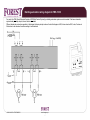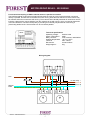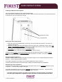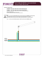
1
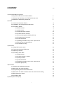
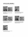
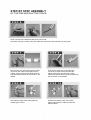
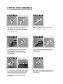
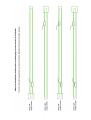
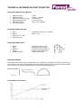
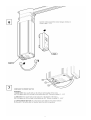
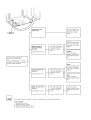
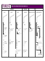
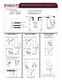
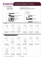
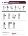
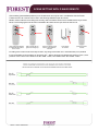
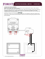
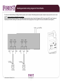
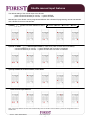
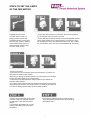
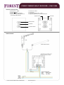
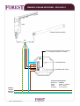
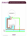
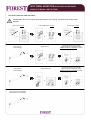
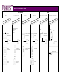
2 CONTENT v1.8 1) Forest motorisation in general 1.0) Important instructions for Forest Shuttle 4 1.1) Step by step assembly of the FMS and Shuttle track 5 1.2) Methode of assembling toothed belt 9 2) Shuttle 2.1) Technical information Shuttle 10 2.2) Installation and configuration Shuttle motor 11 2.3) Controlling Shuttle 17 2.3.0) Multi receiver 18 2.3.1) Multi remote 19 2.3.2) Multi wall switch wireless 20 2.3.3) Z-wave remote / receiver 21 2.3.4) Scene setting (intermediate positions) 22 2.3.5) Programming IR channels 23 2.3.6) Pulse wall switch 24 2.3.7) Building automation relay / actor output control 25 2.3.8) Shuttle manual input features 26 2.3.9) Potential free relay 27 3) FMS motor 3.1) Fixing FMS onto the track 28 3.2) Technical information FMS motor 29 3.3) Adjusting end limits 30 3.4) Controlling FMS / BCS 31 3.4.1) Multi receiver 32 3.4.2) Z-wave receiver / remote 33 3.4.3) Somfy receiver 35 3.4.4) Pulse wall switch 36 3.4.5) Building automation relay / actor output control 37 3.4.6) Motor group relay 38 4) BCS motor 4.1) Assembly and adjusting end limits 39 4.2) BCS motor with receiver build-in 41 4.3) Programming Multi remote to BCS motor 42 4.4) BCS motor with build-in Multi receiver and electronic limit setting 43 4.5) BCS Obstruction sensor 45 4.6) Controlling BCS 46 5) Warranty and return policy 47 3 IMPORTANT INSTRUCTIONS FOREST MOTORISATION Read these instructions carefully before using the Forest Shuttle, FMS and BCS motors and save them for future reference. This Shuttle, FMS and BCS motors is for indoor use ONLY and may not be installed in humid environments such as bathrooms, showers, etc. The Shuttle motor may ONLY be used in combination with the supplied transformer. Do not apply reverse power (wrong polarity) to the Shuttle curtain motor. In case a motor is overheating or smoke comes from the motor, disconnect power immediately. If the Shuttle curtain motor is connected to the transformer and cannot be operated, disconnect power immediately and contact your supplier. Any changes or modifications to the Shuttle, FMS or BCS motor that are not approved by the manufacturer will void the user’s authority to operate the equipment. Forest Group does not assume liability for resulting damages to property or personal injury if the product has been abused in any way or damaged by improper use or failure to observe these operating instructions. The warranty/guarantee will then expire! INSTRUCTION FOR ASSEMBLING FMS/SHUTTLE Necessary items: FMS Track 580cm FMS Track 700cm FMS Transport Belt FMS / CCS Master Carrier Underlap R/L FMS / CCS Master Carrier Overlap R/L FMS / CCS Master Carrier Single Arm R/L FMS Motor Pulley FMS Return Pulley FMS Connector FMS Metal Clip for motor pulley FMS Carrier Articlenumber: 5101001580 5101001700 5105501000 5215801000 5215901000 5216001000 5103011000 5103011100 5103011500 5103011001 2510101000 We advise to make the curtail 10cm wider, to be able to cover the motor and retour pulley completely. 4 STEP BY STEP ASSEMBLY OF THE FMS AND SHUTTLE TRACK Cut the track 10.5cm shorter than the total lenght required. Slide the belt through the track by using the FMS belt connector. Cut the belt under an angle to remove the 1st tooth. This ensures a smooth sliding through the FMS Return Pulley. Take off the cord connector and push the belt through the FMS Return Pulley until the above figure is achieved Cut off the remaining part of the 1st tooth, then attach the belt connector and put the belt back into the other trackchannel until above figure is achieved. Now pull the belt through the track and take off the belt connector at the end. 5 STEP BY STEP ASSEMBLY OF THE FMS AND SHUTTLE TRACK Keep one side of the belt flush with the end of the rail. Now start counting 17 teeth of the belt, mark the 17th tooth of the belt and cut it here after. Now connect one end of the belt to the belt connector and insert the first piece of the master carrier into the track. Make sure the first tooth stays outside the connector, in the middle. Connect the other end of the belt to the connector to make a loop and slide the master carrier fully into the track. Again make sure that the first tooth stays outside of the connector, in the middle. Now take the FMS motor pulley apart by removing the screws. Position the bottom piece of the motor pulley onto the track, make sure the belt falls into place. 6 STEP BY STEP ASSEMBLY OF THE FMS AND SHUTTLE TRACK Now position the center piece onto the motor pulley, making sure the ball bearing falls into place, and place the top piece on the motor pulley again. Slide the master carrier to the end of the track, against the end pulley. On the side of the motor pulley; mark the first visible tooth on the opposite part of the belt where the first master carrier is attached. Remove the motor pulley again from the track. Take off the return pulley and lift it together with the belt up onto the track, like the pictures show. On the side of the motor pulley, slide out the belt, until the marked tooth becomes visible. Now put the belt connector over this tooth. it is very important that the marked tooth is clamped by the connector as shown in the picture. Now position the second master carrier over the belt connector and slide them together into the track. 7 STEP BY STEP ASSEMBLY OF THE FMS AND SHUTTLE TRACK Now reposition the end pulley onto the track an fasten the screw. Now tighten all the screws of the motor pulley again. Place the metal FMS clip inside the track, put the motor pulley on the track again and place the metal clip over the motor pulley, to ensure a good fixation. In order to ensure a smooth running of all the components inside the track, it is necessary to lubricate the track, the pulleys and the master carriers with the special Forest lubrication spray. Finally, position the FMS carriers onto the track and click them into the track, by using your thumbs. Remove the plastic strip. The basic assembly of the track is now complete, the system is ready to be installed with the motor. 8 9 TECHNICAL INFORMATION SHUTTLE MOTOR SPECIFICATIONS SHUTTLE MOTOR: Maximum torque: Maximum speed: Current draw at max. torque: Operating temperature: Weight per carrier: CE / FCC approved 1,5Nm 100rpm ≈ 15cm/sec 2,7A at 24 Vdc 0-50°C / 32-122°F 1,0kg – max. 10kg/mtr SPECIFICATIONS ADAPTOR: Input: Output: CE / FCC / UL / TÜV Efficiency level V 100-240Vac – max.1,5A - 50-60Hz 24Vdc - 2,7A SPECIFICATIONS TRACK: 20mm Weight: Size: Material: Finish: Available lenghts: 303 gr/mtr (3.25 ounce/ft) 20x20mm (0.79x0.79 inch) Aluminium extrusion 6063 T5 Powder coated, lubricated 5.80mtr and 7.00mtr 20mm BENDING/CURVING: The Shuttle motor can be used in a track with one or two bends of 90 degrees. The track can be curved and reversed curved in any horizontal direction with a radius of 20cm (8 inch). Bends with a larger radius and continuous curves can be made with the electrically powered bending tool. min. 55cm (2110/16”) 30cm (1ft.) min. radius 50cm (1911/16”) LOAD TABLE (with carriers): 10 11 12 15. 13 14 15 16 WAYS TO OPERATE THE FOREST SHUTTLE RF WIRELESS MULTI TO ADAPTOR Z-WAVE IR WIRELESS SOMFY TO ADAPTOR INFRA RED TO ADAPTOR WIRED MECHANICAL SWITCH TO ADAPTOR HOME AUTOMATION TO ADAPTOR WIRED TO ADAPTOR WIRED POTENTIAL FREE ACTOR FOREST SHUTTLE MULTI RECEIVER CLICK-ON 5201001362 FOREST Z-WAVE MODULE EU: 5201001750 US: 5201001751 SOMFY DRY CONTACT RECEIVER 5104011420 SHUTTLE IR RECEIVER 5201001260 FOREST PULSE WALL SWITCH 5201001900 OR 230Vac FOREST SHUTTLE MULTI RECEIVER 5201001361 BUS SYSTEM OR FOREST MULTI REMOTE WHITE 5201001460 BLACK 5201006460 FOREST Z-WAVE REMOTE EU: 5201001700 US: 5201001701 SOMFY REMOTE 5104011400 FOREST IR REMOTE 5 CHANNEL 5201001250 DIRECTLY TO SHUTTLE (POTENTIAL FREE OUTPUT) OR AND/OR AND/OR OR RQ BRIDGE FOREST MULTI WALL SWITCH 5201001470 04/2011 WDOC CONTROL SHUTTLE SOMFY TIMER SWITCH 5104011405 PROGRAMMING REMOTE 12 CHANNEL 5201002250 www.forestgroup.nl 17 FOREST MULTI RECEIVER / WALL SWITCH – 5201001360 / 1 / 2 TECHNICAL SPECIFICATION: ● powered by Shuttle ● can also be used as wall switch ● cable 0,5mtr → 5201001360 ● cable 3,5mtr → 5201001361 ● click-on → 5201001362 ● connect to port 1 of the Forest Shuttle ● can control several Shuttles parallel ● working temperature -10°C - +50°C ● works on Forest Multi Remote and Forest Multi Wall Switch RF program button program button control led open/up button stop button close/down button PROGRAMMING REMOTE / WALL SWITCH TO RECEIVER: press program button, led will blink CANCEL ONE CHANNEL OF REMOTE / WALL SWITCH press program button, led will blink or DELETE ALL PREVIOUS PROGRAMMED REMOTES / WALL SWITCHES: press stop and close button of receiver for ~6 sec. or press stop button press stop button press program button, led will light up hold the remote/wallswitch within 0,5 mtr from receiver. Select channel (1-15) and press open button: led must blink 3 times and will go off led will blink and will go off press program button, led will light up or select channel and press close button: led will blink and will go off press and hold the program button for 10 seconds until led starts blinking 11/2013 WDOC SHUTTLE MULTI RECEIVER www.forestgroup.nl 18 FOREST MULTI REMOTE - 5201001460 TECHNICAL SPECIFICATION: ● 3V battery CR2430 ● battery life > 3 years ● frequency 433.92MHz ● transmit power 10mW ● transmit range indoors max. 30mtr ● working temperature -10°C - +50°C ● modes: manual, timer and dynamic timer (15 minutes + and -) ● each channel can control up to 20 receivers / motors selected channel manual/auto/dynamic mode mode button open/up button stop button time button close/down button non applicable channel +/battery slide (CR2430) SET TIME: PRESS MODE TO SET MODE TO MANUAL ‘man’ ON DISPLAY PRESS TIME FOR ~7SEC. → 2 DIGITS WILL BLINK PRESS BUTTONS TO CHANGE TIME PRESS TIME TO TOGGLE BETWEEN HOURS/MINUTES PRESS TIME ~7SEC. UNTIL ALL DIGITS STOP BLINKING PRESS TIME ONCE MORE TO FINISH AND START CLOCK PRESS TIME TO TOGGLE BETWEEN HOURS/MINUTES PRESS MODE TO SWITCH TO CLOSE▼TIME BEFORE SETTING THE TIMER, SET THE CLOCK! SET TIMER (EACH CHANNEL SEPARATE): PRESS MODE TO SET MODE TO AUTO OR DYNAMIC SELECT CHANNEL PRESS TIME FOR ~7SEC. → HOUR DIGITS WILL BLINK PRESS BUTTONS TO CHANGE OPEN▲ TIME PRESS BUTTONS TO CHANGE CLOSE▼ TIME PRESS TIME TO TOGGLE BETWEEN HOURS/MINUTES PRESS TIME FOR ~7SEC. UNTIL DIGITS STOP BLINKING → FINISHED SET MODE TO AUTO OR DYNAMIC 11/2013 WDOC MULTI REMOTE www.forestgroup.nl 19 FOREST MULTI REMOTE - 5201001460 MODE EXPLANATION: Mode manual (man): remote can only be used manually. Timer function is switched off. Mode automatic (auto): timer is switched on, only for the selected channel. Select channel 00 (all channels) to engage on all timers. Mode dynamic ( ): same as automatic mode, open and close time will vary + and – 15 minutes. FEATURES: ● When channel select is set to channel 00, all the channels 1 to 15 will respond to open and close. ● Default timer setting for every channel is: open 06:30AM, close 5:30PM. ● Dynamic mode: timer will vary open and close time between + and – 15 minutes. The first day dynamic mode is used the time will not vary. FREQUENT ASKED QUESTIONS: ● Q: Clock doesn’t start running after setting the time. A: Press time button on the back once more. ● Q: I can’t succeed setting the time or the timer. A: The interval between pressing different button must be within 10 seconds. ● Q: When I set a timer, the display shows Er:01 A: Time between open-time and close-time must be more than 30 minutes apart. ● Q: Timer only works on one channel. A: Only the selected channel will work as a timer. Use channel 00 to turn on all timers (all channels). ● Q: I can’t succeed programming a remote / wall switch RF to a receiver A: During programming, keep the remote / wallswitch RF close to the receiver (max 0,5 mtr) BATTERY EMPTY: After changing the battery, only the time must be set. Programmed receivers will stay in memory of remote. Please follow the local regulations for disposal of the empty battery. FOREST MULTI WALL SWITCH RF - 5201001470 TECHNICAL SPECIFICATION: ● 3V battery CR2032 ● battery life > 3 years ● frequency 433.92MHz ● transmit power 10mW ● transmit range indoor max. 30mtr ● working temperature -10°C - +50°C ● each channel can control up to 20 receivers open/up button stop button close/down button channel A channel B battery CR2032 BATTERY EMPTY: After changing the battery, programmed receivers and timers will stay in memory of remote. Please follow the local regulations for disposal of the empty battery. 11/2013 WDOC MULTI WALL REMOTE / SWITCH RF www.forestgroup.nl 20 Z-WAVE REMOTE / RECEIVER INCLUDING THE SHUTTLE IN A Z-WAVE NETWORK*: select channel press include with pin, green led will light up press button on receiver activate channel press button on receiver press stop to finish EXCLUDING THE SHUTTLE FROM A Z-WAVE NETWORK*: press include/exclude button ~6sec. red led will light up press button on receiver green led will blink twice COPY UNIQUE REMOTE ADDRESS TO 2ND REMOTE*: remote1 press include of 1st remote with a pin remote 2 press open and stop of 2nd remote simultaneous led 1 to 5 will blink fast, address of remote1 is now copied to remote 2 * Keep the remote close to the receiver/2nd remote (max 0,5 mtr). In case of a 3rd party remote/receiver, consult the corresponding manual. To reset a (second) copied remote to its origional unique address, press and hold the SELECT ▲ and ▼ buttons simultaneously for ~5 seconds until all 7 leds light up. Note: in case receiver/remote does not respond, reset receiver to default by pressing the button on the receiver for ~5 seconds until red led lights up. Then try again to include. 04/2011 WDOC ZWAVE www.forestgroup.nl 21 SCENE SETTING WITH Z-WAVE REMOTE Scene setting (intermediate positions) on a Shuttle track can only be use in combination with the Forest Z-wave remote. All 3 scenes can be set in the full range between open and close. NOTE: In order to make the scene setting work correctly, make sure that the curtain track is assembled in the way as shown below, to aviod changing the motor direction of the Shuttle. Also make sure the open and close limits are set. press open/close buttons to select desired position of the curtian press include with pin, green led will light up press the desired scene button, associated led will blink press button on receiver press stop button to finish For setting scene 2 and 3 use the same steps as above, only change scene button 2 or 3. Associated leds (2 or 3) will blink. In case of 5 Shuttles, the scene buttons can be used as ‘ALL’ – buttons. Program every Shuttle open position to scene 1, close position to scene 2. Then scene 1 button is the ‘ALL OPEN’ – button, scene 2 button is the ‘ALL CLOSE’ – button. 05/2011 WDOC SCENE SET www.forestgroup.nl 22 Programming IR channels on Forest Shuttle To program a Forest Shuttle to a different channel you need a 12 channel IR remote control (5201002250). The default setting of the Forest Shuttle is channel 1. To programming a Forest Shuttle put the connector of the IR module in port 1-eye of the Forest Shuttle that you want to program. Remove the IR module from other Forest Shuttles in the same room, otherwise the other Forest Shuttles will be programmed too. Aim the remote control to the IR eye. For re-programming to channel 2 press the next buttons on the remote control: 1) 2) 3) 4) 5) press 3 buttons simultaneously For programming to channel 3 to 5 press the same buttons as above, this button represents the channel number. Channel 3: button OPEN3, channel 4: button OPEN4, channel 5: button OPEN5. When after re-programming you want to change the channel again: follow the same steps as above, only at step 2) use the previous re-programmed channel number. For example: the Shuttle is re-programmed to channel 2, this must be channel 3 → press next buttons: OPEN7+CLOSE7+STOP → OPEN2 → CLOSE1 → OPEN3 → STOP The ALL-buttons will open and close all channels. It is also possible to use universal remote controls (like Logitech, Phillips, Sony, One for All) to control the Forest Shuttle. It must be a learnable remote. Follow the instructions of the universal remote control. Note: when the Forest Shuttle is reset to default by means of the configuration button on the Forest Shuttle, then the IR channel is also reset to default (channel 1). 04/2011 WDOC PROG IR SH www.forestgroup.nl 23 SHUTTLE PULSE WALL SWITCH - 5201001900 CONNECTING THE WALLSWITCH Either of the 2 ports (1-EYE or 2-AUX) can be used to connect a (pulse) switch to open, close or stop the drapery. This is called a dry contact connection. Pins 1, 3 and 8 are used for this. If pins 3 (common) and 1 (open) are connected by means of the switch then the drapery will OPEN. If pins 3 (common) and 8 (close) are connected then the drapery will CLOSE. A standard network cable can be used for this, connect only 3 wires to the wall switch. When the copper wire is too thin to connect, use a ferrules, like: Internal pins 1 and 8 are not connected between ports 1 and 2. Use a splitter to ‘daisychain’ Shuttle motors. These ports can also be used for home automation systems. Be sure the switching (relay) outputs are dead! (free of potential). 8 3 1 11/2010 WDOC5201001900V1.2 8 3 1 www.forestgroup.nl 24 Building automation wiring diagram for Forest Shuttle For control of a Forest Shuttle by a building automation system an actor is needed. If the building automation system already has relay outputs, then an actor is not needed. The relays output must be dead! (free of potential) Different brands and protocols are possible, in this diagram the basic principle is shown. Used in this diagram is KNX, but can also be AMX, Lutron, Creston etc. Depending of the kind of switching, the manual input of the Shuttle must be reprogrammed, like on page 26 of the user and installation manual (option 2). 07/2012 WDOC ACTOR SHUTTLE www.forestgroup.nl 25 Shuttle manual input features The default setting of the manual input of the Shuttle: - pulse connection between pin 3 and 1 → system OPENS, - pulse connection between pin 3 and 8 → system CLOSES. Manual input of the Shuttle can be programmed different with a Shuttle IR programming remote 5201002250 and a Shuttle IR receiver 5201001260: 1) SPST : pulse connection between 3 and 8: OPEN STOP CLOSE STOP 2) STOP on SPDT manual input release (in case when pulse contacts are not available): - connection between pin 3 and 1 → system OPENS until connection is released, - connection between pin 3 and 8 → system CLOSE until connection is released. 3) Swap OPEN and CLOSE on SPDT, invert SPST: Reset manual input features Note: manual input features are also reset to default setting when the Shuttle is reset to default by means of configuration button on Shuttle motor. 04/2011 WDOC SHMANINPUT www.forestgroup.nl 26 POTENTIAL FREE RELAY 5201002230 With this relay 230Vac control signals (for FMS or tubular motor) can be converted to two potential free contacts. These potential free contacts can be used to control Forest Shuttle motors. Control voltage 230Vac Technical specification: Input voltage: 230Vac, 50Hz Output: two potential free contacts Current consumption: 10mA (relay up) Switching power: max. 8A, 250Vac Temp: 0°C - +60°C Terminal: max. 2,5mm² Dimensions: 20 x 47 x 51 to Shuttle manual input (pin 1, 3 and 8) or When the 230Vac control signal is not a pulse signal: change the manual input setting of the Shuttle(s) with a programming IR remote like shown below. Aim the remote control to the IR eye. To set this you need: programming IR remote (5201002250) and IR receiver (5201001260). Note: when the Forest Shuttle is reset to default by means of the configuration button on the Forest Shuttle, then the manual input setting is also reset to default (not stop on manual input release). 04/2011 WDOC5201002230 www.forestgroup.nl 27 FIXING FMS ONTO FMS TRACK Please see page 3 – 6 for assemly of the track First position the motor sideways onto the motor pulley. Now twist the motor onto the motor pulley so the locking slide is aligned, and push it into the motor pulley. Now the motor is ready for set-up and operation. 28 TECHNICAL INFORMATION FMS MOTOR SPECIFICATIONS FMS MOTOR: Torque: Speed: Voltages: Operating temperature: Max. runing time: Weight per carrier: CE / FCC / UL approval 0.8 / 1.2Nm / 1.8Nm (30 / 45 / 60Watt) 100rpm ≈ 15cm/sec 110Vac – 60Hz / 230Vac – 50 Hz 0-50°C / 32-122°F 5 minutes 1,0kg – max. 10kg/mtr SPECIFICATIONS TRACK: 20mm Weight: Size: Material: Finish: Available lenghts: 303 gr/mtr (3.25 ounce/ft) 20x20mm (0.79x0.79 inch) Aluminium extrusion 6063 T5 Powder coated, lubricated 5.80mtr and 7.00mtr 20mm BENDING/CURVING: The FMS motor can be used in a track with one or two bends of 90 degrees. The track can be curved and reversed curved in any horizontal direction with a radius of 20cm (8 inch). Bends with a larger radius and continuous curves can be made with the electrically powered bending tool. min. 55cm (2110/16”) 30cm (1ft.) min. radius 50cm (1911/16”) LOAD TABLE (with carriers): 45 Watt 30 Watt 60 Watt 29 STEPS TO SET THE LIMITS OF THE FMS MOTOR Preferably set the limits of the motor with the motor in a hanging position. Ensure that the Master Carriers of the system are in the open position, meaning the intended position where you want the master carriers to stop when the curtain is open. • Ensure that the two buttons on the bottom of the motor are visible, by removing the white cap of the motor (2A). • Ensure that the two coloured wheels (on the photo depicted as white yellow- white wheels) are in a neutral position. The position in which the indentations in each of the three wheels are in line. This is called the “zero-situation” (2C). The motor comes standard with this setting. • Switch on the power • Press and turn one of the buttons to find out which button you need to set the masters in closed or open position • Because you already moved the masters in the open position you only have to select the setting wheel for the closed position • Press and turn the selected button until the masters have reached the intended ‘closed’ position. • Turn off the power. Press and turn the selected button again to set back the white-yellow-white wheels in the neutral position. You have set the limits now. • To save the settings put the safety clip in the middle position. In order to check if the settings are correct, move the masters by using the remote or the wall switch to the open and closed position. If, for example, the masters are not fully closing in the middle you have to reset this position. Now close the system again and you will see that it stops automatically where you have set the limits as described in step 3. 30 31 FOREST FMS/BCS MULTI RECEIVER - 5104011500 TECHNICAL SPECIFICATION: ● power 230Vac – 500W ● controls one motor ● can also be used as wall switch ● works on to Forest Multi Remote and Forest Multi Wall Switch RF ● terminal max 2,5mm² ● one channel ● working temperature -10°C - +50°C ● programming identical to Shuttle Multi Receiver program button open/up button stop button close/down button WIRING DIAGRAM: 11/2013 WDOC FMS BCS MULTI RECEIVER www.forestgroup.nl 32 control led FMS/BCS Z-WAVE RECEIVER - 5201001812 FMS TUBULAR MOTOR (BCS) OR switch the brown and black wire (1 and 2) to change the direction of rotation UP/OPEN button DOWN/CLOSE button Technical specification: Frequency: 868MHz Power: 230Vac – 460VA Temp: 0°C - +40°C Terminal: max. 2,5mm² 230Vac: PHASE NEUTRAL EARTH 11/2010 WDOC5201001812 www.forestgroup.nl 33 FMS/BCS Z-WAVE RECEIVER - 5201001812 Including a FMS/BCS receiver into a Z-wave controller network: Steps: 1) select channel on the controller by pressing the select button 2) press include/exclude button with a pin, green led on remote will light up 3) press the channel up or down button to activate the channel 4) press 3x quick the UP button on the Z-wave receiver, green led on remote blinks once 5) press stop button on controller, including is completed. Keep the Z-wave remote next to the Z-wave receiver during these steps. Excluding a FMS/BCS receiver from a Z-wave controller network: Press and hold the include/exclude button with a pin (~6 sec.) until the red led on the remote lights up. Press 3x quick the UP button on the Z-wave receiver. The green led on the remote will blink once. Excluding the Forest Shuttle is completed. Keep the Z-wave remote next to the Z-wave receiver during these steps. green led red led UP/OPEN button STOP button DOWN/CLOSE button include/exclude button 11/2010 WDOC5201001812 www.forestgroup.nl 34 SOMFY RECEIVER FOR FMS / BCS - 5104011410 10/2010 WDOC5201001900 www.forestgroup.nl 35 FMS / BCS PULSE WALL SWITCH - 5201001910 FMS TUBULAR MOTOR (BCS) OR Technical specification: Power: 115-230Vac - 10A Temp: 0 - 50°C Terminal: max. 1,5mm² 115-230Vac: PHASE NEUTRAL EARTH 10/2010 WDOC5201001910 www.forestgroup.nl 36 Building automation wiring diagram for FMS / BCS For control of a FMS (Forest Motorized System) or BCS (Blind Contract System) by a building automation system an actor is needed. If the home automation system already has relay outputs, then an actor is not needed. Different brands and protocols are possible, in this diagram the basic principle is shown. Used in this diagram is KNX, but can also be AMX, Lutron, Creston etc. Motors have to be connected to earth according to local standards. 03/2013 WDOC ACTOR FMS BCS www.forestgroup.nl 37 MOTOR GROUP RELAY - 5201002240 For electrical decoupling of FMS or tubular motors in parallel connection. The FMS and tubular motors with mechanical limit-switches must as a rule not be electrically connected directly in parallel, because due to the different motor running times the limit-switches of some motors may be reached while other motors are still running. The motors that are already switched off would then receive inductive voltage at the counter-winding from the motors that are still running, which can lead to destruction of the limit-switches. The Motor Group relay is providing an extremely simple method of achieving a (functional) parallel circuit. Several relais can be connected parallel. Technical specification: Operating voltage: 230Vac 50Hz Power consumption: 0.6W Relay contacts: 4 NO contacts, 10A/250Vac Ambient temperature -10°C to +45°C Terminal: max. 2.5mm² Dimensions: 43x43x18.5mm Weight approx.: 40g Wiring diagram: Line open close to next relay → . Neutral Earth E 06/2011 WDOCMOTRELAY www.forestgroup.nl 38 E BLIND CONTRACT SYSTEM Keep in mind: ● the profile must be cut 1,5cm shorter than the total width of the system ● the octogonal tube must be cut 5,5cm shorter than the profile, or 7cm shorter than the total width of the system ● BCS profile lenght is max. 5,80 mtr. ● BCS curtain height is max. 5,50 mtr. ● max. weight for one cord roll is 4kg ● total weight of the curtain is 2,5 – 3 kg for each Nm torque of the tubular motor ● use this table to determine the amount of cord rolls: Tracklength (in cm): 0 – 134 135-189 190-223 240-314 315-364 No of cord rolls: 3 4 5 6 7 Tracklength No of cord (in cm): rolls: 365-399 8 400-444 9 445-489 10 490-534 11 535-580 12 Assembly of the Blind Contract System Attach the octogonal adaptors to the tubular motor. Slide the motor into the octogonal tube and operate the motor in one direction until an end position is reached. If metal parts are fixed on the motor head, unscrew and remove these. Assemble the system according to the exploded view below. The adjustment screws on the motor must be accessible from the lower side. Unwind the cord rolls and make sure all cord rolls are alligned in the same position on the octogonal tube 03/2012 WDOCBCS www.forestgroup.nl 39 BLIND CONTRACT SYSTEM Installing the Blind Contract System Use one wall/ceiling bracket for every 50-60cm track length. Mount the system on wall/ceiling and attach the fabric. Attach the snap cord fixers on the cords at the bottom of the blind. Do not cut off the exces cord yet. adjustment screws octogonal tube Setting the motor end positions ● when the track is pre-assembled the cord is fully unwound (closed blind position). The lower end position is already set. ● Adjusting the upper and lower end positions is done by turning the 2 adjustment screws. Use a 4mm hex key, never a battery screwdriver. Which screw to adjust up and which screw to adjust down depends on the direction of rotation ot the octogonal tube. ● One rotation of an adjustment screw is ± 3cm blind height. ● make sure that the cords never hang loose when the motor is running. Control the blind upwards. Look at the octogonal tube and remember the direction of rotation. Make a mark (with a permanent marker) next to the arrow with this direction of rotation. The screw next to this arrow is the adjustment screw for the upper position. Adjust the upper endposition: Control the blind upwards. To adjust the upper end position higher, turn the marked adjustment screw to direction +, until the desired height is reached. If the upper end position is too high, turn the marked adjustment screw to direction -. Control the blind downwards and upwards again. Repeat until desired height is accomplished. Adjusting the lower endposition: Control the blind downwards. To adjust the lower end position lower, turn the unmarked adjustment screw to direction +, until the desired height is reached. If the lower end position is too low, turn the unmarked adjustment screw to direction -. Control the blind upwards and downwards again. Repeat until desired height is reached. The motor should never make noise when it has stopped in the upper position. This happens when the upper endposition is adjusted too high. The motor or cord could breakin this case. 03/2012 WDOCBCS www.forestgroup.nl 40 BCS TUBULAR MOTOR - BUILD-IN RECEIVER AND ELECTRONIC LIMIT SETTING TECHNICAL SPECIFICATION: ● 3416600099 – 6Nm, 33rpm, build-in receiver, electronic limit setting (110V) ● 3416600110 – 3Nm, 28rpm, build-in receiver, mechanical limit setting (230V) ● 3416600112 – 6Nm, 28rpm, build-in receiver, electronic limit setting (230V) ● 3416600116 – 13Nm, 14rpm, build-in receiver, electronic limit setting (230V) ● 3416600117 – 6Nm, 20rpm, build-in receiver, electronic limit setting, Quiet (230V) ● max. running time 4 min. ● protection degree IP44 (230V), class B (110V) ● has to be used with Multi remote and/or Multi wall switch RF IMPORTANT 230V: use only wires BROWN (phase), BLUE (neutral) and GREEN/YELLOW (earth). The additional two wires are for connecting the optional obstruction sensor. Make sure these two wires do NOT make contact with power or connect together. 110V: use only wires BLACK (phase), WHITE (neutral) and GREEN (earth). 230Vac: PHASE NEUTRAL EARTH 07/2013 WDOC3416600XXX www.forestgroup.nl 41 BCS TUBULAR MOTOR - BUILD-IN MULTI RECEIVER AND ELECTRONIC LIMIT SETTING PROGRAMMING REMOTE / WALL SWITCH TO TUBULAR MOTOR (button presses within 6 seconds) ADD MORE REMOTES / WALL SWITCHES / CHANNELS TO TUBULAR MOTOR (button presses within 6 seconds) first select the desired channel first select the desired channel press button on motor, motor will turn short to acknowledge 1st remote: press button two times CANCEL ALL REMOTES OR WALL SWITCHES (button presses within 6 seconds) press button one time or press button two times 2nd remote: press button one time or or or or motor will turn to acknowledge to add another channel on the same remote: select the programmed channel, press button on back of remote 2 times, select desired channel and press button on the back. Motor will turn to acknowledge. motor will turn to acknowledge or or press button one time or or motor will turn to acknowledge To change the direction of rotation, keep green button on motor pressed for 7 sec, until motor turns to acknowledge. 07/2013 WDOC3416600XXX press STOP button one time or or press OPEN-button one time or www.forestgroup.nl 42 BCS TUBULAR MOTOR WITH BUILD-IN RECEIVER AND ELECTRONIC LIMIT SETTING ADJUSTING UPPER AND LOWER END LIMITS: IMPORTANT: when more motors are programmed to one channel, end limits of all motors will be adjusted press button one time press OPEN button one time or press button one time or or or or or motor will turn to acknowledge adjust UP limit press STOP button when required height is reached. Press STOP button 5 times slowly for 1 seconds to confirm or or motor will turn to acknowledge adjust DOWN limit or motor will turn to acknowledge, limits has been set successfully. 07/2013 WDOC3416600XXX www.forestgroup.nl 43 or press STOP button when required height is reached. Press STOP button 5 times slowly for 1 seconds to confirm or BCS TUBULAR MOTOR WITH BUILD-IN RECEIVER AND ELECTRONIC LIMIT SETTING CANCELLATION OF UPPER AND LOWER END LIMITS: IMPORTANT: When cancelling end limits, all motors programmed to that channel will be cancelled press button one time press CLOSE button one time or or or or motor will turn to acknowledge, limits has been set successfully. REVERSE DIRECTION SETTING: When motor is not running, press button on motor for ~ 7 seconds, until motor turns to acknowledge. 07/2013 WDOC3416600XXX press button one time www.forestgroup.nl 44 or or OBSTRUCTION SENSOR SET - 3416800000 This product must be installed by a person with professional knowledge. The installer must comply with the current standards and legislation in the country in which the product is being installed. Only possible for 230Vac tubular motor. With this set a BCS motor will stop turning when something is blocking the roman blind. This prevents the cords from getting stuck when lowering the blind. This set can only be used in combination with a Forest tubular motor with build-in receiver and mechanical or electronic limit setting. Use two sensors per system on the outside cord rolls. Systems wider than 3 meter (10 ft.) need a third sensor in the middle. Assembly of the obstruction sensor set: Push the cord through the sensor as shown in picture 1 to 4. When the cord is pulled (picture 4), then a ‘click’ can be heard. picture.1 picture.2 picture.3 picture.4 Push the obstruction sensor in the BCS track as shown in picture 5 and 6. picture.5 picture.6 picture.7 Connecting: included in the set is a cable for connecting the sensors to the motor. Use only two wires of the cable (e.g. red and green). Connect these wires to the sensor as shown in picture 7. The sensors need to be connected in parallel to the black and white wire of the motor cable. Make sure that in no way the wires from the sensor, or the black and white wire make contact with the blue, brown or yellow/green wires. 03/2012 WDOC3416800000 www.forestgroup.nl 45 WAYS TO OPERATE BCS RF WIRELESS MULTI MULTI BUILD-IN WIRED Z-WAVE SOMFY MECHANICAL SWITCH FOREST TUBULAR MOTOR RECEIVER BUILD-IN 3416600110 3416600112 3416600116 CORDED CORDED ACTOR FOREST MULTI FMS/BCS RECEIVER 5104011500 FOREST Z-WAVE MODULE FMS/BCS (EU ONLY) 5201001812 230Vac HOME AUTOMATION 230Vac SOMFY RECEIVER 5104011410 230Vac 230Vac FOREST FMS/BCS PULSE WALL SWITCH 5201001910 230Vac BUS SYSTEM FOREST MULTI REMOTE WHITE 5201001460 BLACK 5201006460 FOREST MULTI REMOTE WHITE 5201001460 BLACK 5201006460 FOREST Z-WAVE REMOTE EU: 5201001700 US: 5201001701 SOMFY REMOTE 5104011400 OR DIRECTLY TO FMS AND/OR AND/OR FOREST MULTI WALLSWITCH 5201001470 04/2011 WDOC CONTROL BCS AND/OR FOREST MULTI WALLSWITCH 5201001470 SOMFY TIMER SWITCH 5104011405 www.forestgroup.nl 46 1/1 WARRANTY & RETURN POLICY Forest Shuttle® Motors, BCS® and FMS® Devices. 1. The Forest Shuttle Motor and Control Devices are warranted against defects of components and workmanship for ten (10) years from the date of purchase from the Forest Group Nederland B.V. factory. The BCS and FMS Devices are warranted against defects of components and workmanship for five (5) years from the date of purchase from the Forest Group Nederland B.V. factory. The warranty is applied when only parts of Forest Group B.V. are used in the system. 2. Should any failure to conform with this warranty appear during the specified period under normal and proper use, and provided that the motor and devices have been properly stored, installed and maintained with due regard to any directives, instructions and operating procedures provided by the manufacturer, Forest Group Nederland B.V. shall, upon presentation of proof of purchase, correct such nonconformity either by repair or by replacement of the nonconforming part, Ex Works, at the option of Forest Group Nederland B.V. Return of motors or devices pursuant to this paragraph shall be at purchaser’s risk and expense. 3. Forest Group Nederland B.V. warrants motors and devices, repaired or replaced pursuant to the foregoing warranties, under normal and proper use, storage, installation and maintenance, against defects in materials for a period of thirty (30) days from date of start-up of such repaired or replaced motors or devices or the expiration of the original warranty, whichever is longer. The foregoing warranties do not cover defects resulting from misuse or failure to follow instructions. They also do not cover labour on location, service calls, reinstallation or expenses involved in shipping, packing or returning goods. In no event shall Forest Group Nederland B.V. be liable for any indirect, incidental, consequential or other damages in connection with this product. This disclaimer applies both during and after the period of this warranty. In no event shall Forest Group Nederland B.V. be responsible for providing working access to the defect, including disassembly or reassembly of motors, hardware or devices. Return Policy Forest Group Nederland B.V. products are customized, and as a rule, they cannot be returned. Any goods to be returned to the Forest Group Nederland B.V. factory for repair, credit or otherwise must be clearly marked with the RGA (Return Goods Authorization) number issued by the Forest Group Nederland B.V. customer service department. No return goods will be accepted unless clearly marked with an RGA number. Any return shipment to Forest Group Nederland B.V. must be freight prepaid. All shipments from the Forest Group Nederland B.V. factory will be made EXW, freight collect, best way, unless arranged otherwise. Final acceptance of returned goods is subject to factory inspection. Restocking charges will apply. 47