1
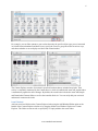
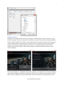
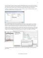
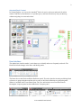
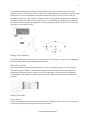
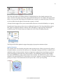
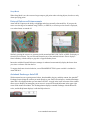
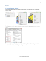
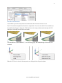
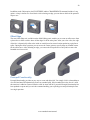
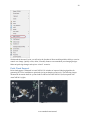
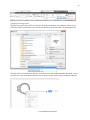
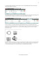
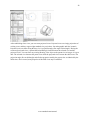
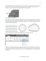
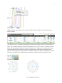
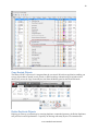
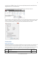
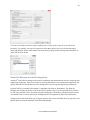
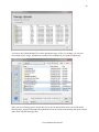
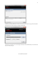
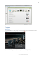
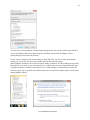
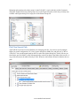
® AutoCAD 2012 Preview Guide Design and shape the world around you with the powerful, flexible features found in AutoCAD® software, one of the world’s leading 2D and 3D design applications. With robust 3D tools that can create almost any shape imaginable, AutoCAD helps you intuitively explore design ideas. It offers innovations that can increase design and documentation efficiency, and enables you to more securely, accurately, and seamlessly share those designs with colleagues. Powerful programming tools and thousands of available add-ons provide the ultimate in flexibility, helping you customize AutoCAD software for your specific needs. With these capabilities and more, AutoCAD delivers the power and flexibility needed to take documentation and design further. 2 Table of Contents Introducing AutoCAD 2012 ......................................................................................................................... 4 User Interaction and Modernization ............................................................................................................. 4 Performance Improvements ...................................................................................................................... 4 Autodesk Content Explorer....................................................................................................................... 4 User Interface ............................................................................................................................................ 9 AutoComplete Command Entry ............................................................................................................. 10 Multifunctional Grips.............................................................................................................................. 10 Nudge Functionality................................................................................................................................ 11 Quick Properties...................................................................................................................................... 11 Object Selection ...................................................................................................................................... 11 External Reference Enhancements.......................................................................................................... 13 Autodesk Exchange–AutoCAD .............................................................................................................. 13 Explore ........................................................................................................................................................ 14 In-Canvas Viewport Control ................................................................................................................... 14 UCS Enhancements ................................................................................................................................ 15 3D Associative Array.............................................................................................................................. 17 Creation Preview..................................................................................................................................... 18 Chain and Loop Selection ....................................................................................................................... 19 Offset Edge ............................................................................................................................................. 20 Presspull Functionality............................................................................................................................ 20 Trimmed Surface Properties ................................................................................................................... 21 3D Autosnap Marker............................................................................................................................... 21 Solid History ........................................................................................................................................... 22 3Dconnexion Support ............................................................................................................................. 22 Autodesk Fusion ..................................................................................................................................... 22 Point Cloud Support................................................................................................................................ 24 Document .................................................................................................................................................... 25 3D Model Import .................................................................................................................................... 25 Model Documentation ............................................................................................................................ 25 Annotation............................................................................................................................................... 31 Osnap Enhancements .............................................................................................................................. 33 Fillet, Chamfer, Blend, and Join ............................................................................................................. 34 www.autodesk.com/autocad 3 Spline Enhancements .............................................................................................................................. 35 2D Array Functionality ........................................................................................................................... 36 Copy Tool ............................................................................................................................................... 39 Layer Enhancements ............................................................................................................................... 39 Copy Nested Objects............................................................................................................................... 40 Delete Duplicate Objects ........................................................................................................................ 40 Communicate .............................................................................................................................................. 41 Raster File Support ................................................................................................................................. 41 DGN Support .......................................................................................................................................... 42 DWG Convert ......................................................................................................................................... 42 Sheet Set Manager and Vault Integration ............................................................................................... 44 Materials Library .................................................................................................................................... 45 AutoCAD WS ......................................................................................................................................... 47 Customize ................................................................................................................................................... 52 Installation............................................................................................................................................... 52 Migration and Customization ................................................................................................................. 53 Plot Files Search Path ............................................................................................................................. 55 www.autodesk.com/autocad 4 Introducing AutoCAD 2012 New and expanded workflows for model documentation, reality capture, and 3D conceptual design help increase productivity with AutoCAD 2012. Explore your design ideas with powerful surface modeling tools. Quickly create documents from a variety of modeling formats, helping to reduce manual documentation workarounds. Capture and import as-built information to jumpstart your design process. Plus, you’ll find a wide range of timesaving enhancements to the features you use most. AutoCAD 2012 delivers the powerful tools you need to participate in smooth 3D design workflows, helping drive your projects to completion more quickly than ever before. User Interaction and Modernization AutoCAD 2012 enhances the way you interact with the software from concept through completion. With noticeable improvements to performance, expanded online resources, and fast, intuitive access to commands and editing tools, you will spend less time focusing on the software and more time advancing your designs. Performance Improvements AutoCAD 2012 offers improved performance in many areas. Enjoy faster startups, particularly when running on Windows Vista® or Windows® 7. Inside AutoCAD 2012, you’ll discover nearly instantaneous response as you switch between ribbon tabs. AutoCAD 2012 also offers improved performance when opening large 3D models with lofts and meshes and when orbiting large 3D models. Additional performance improvements can be found with selection highlighting, licensing checkout, and when running LISP routines. Autodesk Content Explorer Quickly find design content based on file objects or text attributes. The Autodesk® Content ExplorerTM functionality creates an index of your data based on where you instruct it to look, helping you quickly access files. You can explore, or browse into, DWGTM files in order to access and insert blocks, layers, linetypes, styles, and more. Unlike the Design Center tool, Content Explorer is built on a Google®-like index, so you can quickly search for design objects across folders containing thousands of files; the results appear instantaneously. In addition, Content Explorer provides a single interface for browsing and searching other content sources, such as Autodesk® Seek web service. Easily access Content Explorer with the Explore tool on the Plug-ins ribbon tab. In the Content Explorer window, use the Search field to find design content on your local computer, one or more network locations, and the Autodesk Seek site. A pull-down menu allows you to choose from the available locations. www.autodesk.com/autocad 5 You can locate specific block references or text strings, including block attribute data. Quickly determine how many references there are in a file or find a particular reference across multiple files. Easily drag content from the Content Explorer window into your current drawing. You can also right-click or doubleclick content in the Content Explorer window to automatically open the source file and zoom into relevant objects such as text. You can expand and collapse each panel in the search results to easily view all the results. Control the type of content and the format in which it is displayed using the Filter Settings and View Options tools in the lower right corner of the Content Explorer. www.autodesk.com/autocad 6 For example, you can filter content so your results show only the specific object types you are interested in. Switch between thumbnail and detail views, specify the icon size, group the results in various ways, and choose whether or not to display text labels and column headers. The Content Explorer searches for content in specified locations that are included in an index. Their activity is continually monitored by the Content Service, which is installed with AutoCAD, and the index is automatically updated to reflect changes. By default, the search index includes the AutoCAD Sample and Downloaded Content folders as well as the Autodesk Seek site. You can easily add your own local and network content to the index. Local Content Add your own local folders to the Content Explorer index using the Add Watched Folder option at the bottom of the Content Explorer window or by dragging folders from Windows Explorer to Content Explorer. The folders are not moved or copied; they’re simply added to the search index. www.autodesk.com/autocad 7 Network Content In addition to searching content on your local computer, Content Explorer can also search one or more network computers. However, it requires the Content Service to run on the network computers and build an index on that machine. This provides a single index that all clients can access and search. Therefore, in order to support searching on network drives, software needs to be installed separately on the network computer. This software, called Autodesk Content Service, is available from your AutoCAD 2012 installer under Tools and Utilities. Make sure this program is checked; then install it on one or more network computers. Once the Content Service is installed on the network computer, you can add one or more network folders to be watched. Adding watched folders enables the content service to build an index for the files in those folders. The key difference between watched folders on the local machine and watched folders on the www.autodesk.com/autocad 8 network computer is that on a network computer watched folders need to be shared folders in order for AutoCAD users to be able to access and search them. To add network shares as watched folders, launch the Content Explorer Console, which is located in the Windows Start menu under All Programs > Autodesk > Content Service>Content Service Console. When you choose Add Watched Folder, you’ll notice that only shared folders are available to select. After Autodesk Content Service has been installed on one or more network computers, and watched folders have been configured, you can add these network locations as content sources within Content Explorer in AutoCAD. In the lower right corner of the Content Explorer window, choose Configure Settings to display a dialog box with various content sources that you can search and access. Then, in the lower left corner of the Configure Settings dialog box, choose Add Network Content. Simply specify the computer name or IP address of the network computer (for example, \\serv1230001, 10.23.58.88). The network content is easily searchable from the Content Explorer and, thanks to indexing, produces quick results. www.autodesk.com/autocad 9 Autodesk Seek Content In Content Explorer, you can use the Autodesk® Seek web service to browse and search for online content. Find files by manufacturer or via product specs, and insert files directly into your drawing without navigating to an external website. User Interface The updated user interface makes it easier than ever to identify and access frequently used tools. The Home tab includes changes in the Draw and Modify panels. The Insert tab now has Block and Block Definition panels. The tools related to inserting and editing block references are grouped together and the tools to create or edit block definitions are grouped together. Wblock is included in the Create Block flyout. The View tab includes a new Forward tool and a Rectangular viewport option has been added to the Viewports panel. www.autodesk.com/autocad 10 AutoComplete Command Entry AutoCAD 2012 now offers auto-complete options to help you access commands more efficiently. As you type in the Command prompt (or use dynamic input), AutoCAD automatically completes the entry with an AutoCAD command or command alias. If you pause, it displays a list of all the commands whose prefix matches what you’ve typed, enabling you to scroll and select from the list. A right-click menu provides easy access to the new AutoComplete controls, including the ability to display system variables and specify the delay response for displaying the AutoComplete list. In the Command window, the command history is distinguished from the active command line with a grey background color. You can modify the various colors associated with the command window using the Drawing Window Colors dialog box, which is accessible from the Display tab of the Options dialog box. Multifunctional Grips The power of multifunctional grips has been extended to more AutoCAD objects, including lines, arcs, elliptical arcs, dimensions, and mleaders, as well as 3D faces, edges, and vertices. Access relevant options for the selected object by hovering the cursor over a grip. www.autodesk.com/autocad 11 Using multifunctional grips with dynamic input turned on allows you to edit the object via relevant dimensional values. For example, when you choose the Lengthen option for a selected line, dynamic input dimensions for the total length and the incremental length are displayed. You can use the Tab key to switch between the two values. Similarly, elliptical arcs have been updated to support dynamic input for the major and minor axes. When you hover the cursor over a quadrant grip with dynamic input enabled, the distances from the center to the quadrants are displayed along the major and minor axes. If you click on the grip, you can edit the values. Nudge Functionality New Nudge functionality is useful when you need to move selected objects a few pixels in an orthogonal direction. Simply press Ctrl and the appropriate arrow key. Quick Properties Use the Quick Properties tool (QP command alias) to view and modify properties of a selected object. The Quick Properties window is automatically displayed when you double-click on most objects. It’s automatically dismissed when the selection set is cleared and doesn’t come back until you launch the command again. The default list of quick properties has been updated to include more frequently used properties. Object Selection Object Groups Group functionality has been streamlined in AutoCAD 2012 making it easier to use. You can access the new Group tools from the Group panel on the Home ribbon tab. www.autodesk.com/autocad 12 The Group tool replaces the traditional Object Grouping dialog box with a simple prompt to select objects. You have the option of providing a group name and description. The Ungroup tool ungroups the objects. You can use the Edit Group tool to add and remove objects or to rename the group. These tools are also available from the right-click menu when a group is selected. A Group Selection toggle allows you to control whether objects are selected individually or as a group. Expanding the Group panel provides access to additional Group tools. The Group Bound Box controls how groups are displayed. When it’s enabled, AutoCAD displays a single grip and a bounding box around the group. The Named Groups tool displays the classic Object Grouping dialog box. The Purge tool has been updated to support the purging of groups that contain no objects. Implied Selection Pick variables offer more flexibility and control when selecting objects. When you pick the first point of an implied window, you now have the ability to use a Wpolygon, Cpolygon, and Fence in addition to the traditional window selection method. And you no longer have to choose between picking two points or picking and dragging to determine the selection window. The PICKDRAG system variable includes a new option (PICKDRAG=2) that combines both of these methods. The PICKAUTO system variable includes a new option (PICKAUTO=2) that allows you to start a window or crossing selection even when picking on an object. This minimizes the need for you to find a ―clean‖ spot for picking. www.autodesk.com/autocad 13 Snap Mode When Snap Mode is on, the cursor no longer snaps to grid points when selecting objects, but does so only when specifying points. External Reference Enhancements AutoCAD 2012 improves the ability to highlight and select externally referenced files. If you pass the cursor over the edge of an attached image, DWFTM, or PDF file, a selection preview frame is displayed, even when frames are turned off. Similarly, passing the cursor over geometry inside an attached DWF, PDF, DGN, or DWG file displays a selection preview frame. You can select the frame for any of the attached reference files to display a frame boundary, with the ability to grip-edit a clipped boundary frame. Interaction with the External References manager is enhanced to automatically display the frame when you select a reference file from the list. To support the frame selection behavior, a new FRAMESELECTION system variable is included in AutoCAD 2012. Autodesk Exchange–AutoCAD With connected access to getting started videos, downloadable plug-ins, and help content, the Autodesk® Exchange feature brings the content you need directly to your AutoCAD workspace. Autodesk Exchange– AutoCAD is first displayed when you start AutoCAD 2012. A toggle in the lower left corner of the window allows you to disable it on startup but you can access it at any time from the Infocenter in the upper right corner of the AutoCAD window. The Exchange button displays Autodesk Exchange with the Home tab active, and the Help button displays it with the Help tab active. www.autodesk.com/autocad 14 Explore In-Canvas Viewport Control New viewport controls enable you to change viewport settings, views, and visual styles directly on the viewport canvas. The 3D Modeling tab of the Options dialog box includes controls for displaying the in-canvas viewport controls. You can specify the color of the viewport control in the Drawing Window Colors dialog box, which is accessible from the Display tab of the Options dialog. www.autodesk.com/autocad 15 UCS Enhancements AutoCAD 2012 provides many enhancements that make the UCS faster and easier to use. The UCS icon has been updated to allow direct manipulation. You can select the UCS icon and then use the multifunctional grips to change the UCS. Easily move the origin, and automatically align the UCS with objects, including curved surfaces and solids. You can rotate the UCS around the X, Y, or Z axis using grips, and without having to access the UCS command. When the UCS icon is selected, relevant options are displayed in the Properties palette. www.autodesk.com/autocad 16 A new control on the Settings tab of the UCS dialog box enables you to specify whether the UCS icon is selectable. You can access the UCS dialog box from the Coordinates panel of the View ribbon tab when the 3D Modeling workspace is active. Easily access additional UCS controls from a shortcut menu by right-clicking over the UCS Icon. You can modify the shortcut menu to meet your needs using the Customize User Interface dialog box. When you access the UCS through the UCS command, AutoCAD 2012 displays a dynamic preview of the UCS icon, making it easier to understand and provide needed feedback for UCS options. www.autodesk.com/autocad 17 3D Associative Array The associative array functionality that is so valuable for 2D documentation is equally useful for 3D modeling. Each of the three types of associative arrays—rectangular, polar, and path—include the ability to array selected objects in 3D space. Use the Level option to specify the number items in the Z direction during or after array creation. Whether you create one- or multiple levels of array objects, you can specify an increment value for row elevation. When the row elevation increment is set to zero, as it is by default, all rows are created at the same elevation. When set to any other value, positive or negative, the elevation of each row is incremented by that amount. When creating a path array, you can specify whether the arrayed objects should maintain a vertical orientation (Z direction) or adjust to remain parallel to the path. www.autodesk.com/autocad 18 Creation Preview A new preview provides a visual cue indicating when a surface or solid is in an intermediate state during creation. For example, as you select profiles to create a lofted solid or surface, an updated preview of the resulting object is displayed with each selection. In addition to solid and surface lofts, the preview is included with the following commands: SURFBLEND, SURFPATCH, SURFFILLET, FILLETEDGE, CHAMFEREDGE, and LOFT. The preview displays with a transparency to easily distinguish it from completed objects. You can control the transparency level with the new PREVIEWCREATIONTRANSPARENCY variable. www.autodesk.com/autocad 19 Chain and Loop Selection AutoCAD 2012 includes new Chain or Loop options to simplify the process of selecting a set of contiguous edges or curves. The new Chain selection option detects if there is a set of contiguous edges within a solid or mesh object, or within or between surfaces. The chain may either be open or closed and is available in the SURFPATCH, SURFBLEND, MESHCAP, and FILLETEDGE commands. The Chain option within the FILLETEDGE command identifies and fillets edges that have continuity. For example, the part below on the left does not have rounded corners so the fillet operation is limited to the selected edge. The part on the right, however, has rounded corners enabling the Chain option to select and fillet all the continuous edges. www.autodesk.com/autocad 20 In addition to the Chain option, the FILLETEDGE and the CHAMFEREDGE command include a Loop option. A loop is similar to a closed chain. After selecting an edge, you can choose which of the potential loops to use. Offset Edge The new Offset Edge tool, available on the Solid Editing panel, enables you to create an offset curve from a planar face or from a surface where all the edges lie on the same plane. After you select a face, the edge of the face is dynamically offset to the inside or outside based on cursor location producing a polyline or spline. During the offset operation, you can access the Corner option to specify sharp or rounded corners for the offset curve. After offsetting an edge, you can use the Presspull tool to easily add or remove the bounded area from a solid. Presspull Functionality Presspull functionality provides an easy way to create and edit solids. You simply click in a bounded area of a solid and AutoCAD dynamically creates an extruded solid. If the bounded area is the face of a solid, the extrusion is added or removed from the solid. In AutoCAD 2012, powerful Presspull functionality has been updated to repeat until you exit the command enabling you to quickly press and pull multiple times in a single operation. www.autodesk.com/autocad 21 Trimmed Surface Properties The Properties palette for trimmed surfaces is updated to provide more control and flexibility. A new Trims pane displays trim properties for the selected surface. It includes an Edge property, which cycles through the edges and highlights them in the drawing. The new Associative Trim property indicates if the current edge is associative. You can remove the associativity for any given edge. 3D Autosnap Marker The Autosnap Marker control in the Drawing Window Colors dialog box is renamed to 2D Autosnap Marker and a new 3D Autosnap control was added. With different colors, you can more easily distinguish between 2D and 3D osnaps in the drawing editor. www.autodesk.com/autocad 22 Solid History Solid history is turned off by default in AutoCAD 2012. With solid history turned off, you can directly edit faces, edges, and vertices of solids. To retain solid history, you can set the SOLIDHIST system variable to 1. 3Dconnexion Support Support for 3Dconnexion devices is improved in AutoCAD 2012. The precision and controllability of 3D mouse movements were further optimized to provide a more superior 2D and 3D navigation experience. In Walk and Fly modes, the navigation speed accelerates as the camera position moves away from the model. With Object mode, a consistent zoom speed is maintained regardless of the model size or position of the camera within the drawing. Autodesk Fusion Autodesk® Inventor® Fusion adds to the 3D conceptual design capabilities of AutoCAD and sets a new standard for professional 3D modeling ease of use. It enables you to flexibly edit and validate models from almost any source, helping you further experience the benefits of accessible 3D in the native DWG format. Inventor Fusion showcases intuitive direct manipulation capabilities, provides direct modeling for rapid design changes, and unites direct and parametric workflows within a single digital model. When installing AutoCAD 2012, you have the option to install Autodesk Inventor Fusion 2012. www.autodesk.com/autocad 23 If you choose to install Fusion, you will find an Edit in Fusion tool on the Plug-ins ribbon tab in AutoCAD 2012. You can use this tool to select any of the following 3D objects in your AutoCAD drawing to automatically open it for editing in Autodesk Inventor Fusion: 3D Solid Extruded Surface Lofted Surface Planar Surface Swept Surface Revolved Surface NURBS Surface You will also find the Edit in Fusion option on the right-click menu whenever one of those objects is selected. www.autodesk.com/autocad 24 With Autodesk Inventor Fusion, you will enjoy the freedom of direct modeling with the ability to exercise control over change. Quickly create, delete, or modify features to accommodate your changing designs. Make unique design changes and explore ―what if‖ scenarios. Point Cloud Support Point cloud support is enhanced in AutoCAD 2012. It includes an improved indexing algorithm for generating PCG files in addition to optimized viewing at changing zoom levels. The following images illustrate the increased detail for a point cloud file indexed in AutoCAD 2012 (left) compared with AutoCAD 2011 (right). www.autodesk.com/autocad 25 Document 3D Model Import Import a wide variety of file formats, including CATIA®, NX®, Parasolid, Pro/Engineer®, Rhinoceros®, and SolidWorks®, as a starting point for documenting your designs in AutoCAD. You can access the Import tool from the Import panel of the Insert ribbon tab. In the Import File dialog box, open the Files of Type drop-down list to select the desired file format. While the import operation is in progress, an Import icon is displayed on the status bar tray. A bubble notification indicates when the import process is complete and a link in the bubble notification displays the translated file name. You can pass the cursor over the link to view the full path and file name. The ability to import these file formats supports surfaces, solids, and 2D and 3D wire geometry. The data is translated to native AutoCAD geometry and inserted into the drawing as blocks. Parts and assemblies in the original models are preserved and replicated as nested blocks. After importing, you can freely modify the data using standard AutoCAD editing tools and document the 3D models using the new model documentation tools. Model Documentation Save time by automatically generating intelligent documentation for AutoCAD, Inventor, and other models. Drawing views, edge display, and location are instantly updated when an engineering change is made. Access the model documentation tools from the Drawing Views panel of the Annotate ribbon tab. www.autodesk.com/autocad 26 Creating Drawing Views The Base View tool creates a 2D view from the 3D solids and surfaces in modelspace. If there are no surfaces or solids in modelspace, you can select an Inventor project and model (ipt, iam and ipn) files. The Base View tool automatically displays a scaled preview of the model attached to the cursor. As you place the base view on the drawing layout, you can specify options such as type, orientation, and scale. www.autodesk.com/autocad 27 A contextual ribbon tab displays relevant controls, which vary depending on the source of the model, AutoCAD modelspace or Inventor. If an Inventor model is the source for the base view, an additional panel is displayed in the Drawing View Creation ribbon tab, enabling you to further control the representation of the model. If the Type option is set to Base and Projected, rather than Base Only, you can automatically create projected views after placing the base view. Simply drag the cursor to the desired location and AutoCAD automatically creates the appropriate view. You can continue adding projected views later using the Projected View tool. Each view creates a new Drawing View object, which includes a boundary similar to a viewport but does not print. An icon in the status bar tray indicates when a drawing contains drawing views, and you can view and modify properties for a selected drawing view using the Properties palette. www.autodesk.com/autocad 28 After establishing a base view, you can create projected views. Projected views are simply projections of existing views, and they support eight standard view projections: four orthographic and four isometric. Projected views are drawn using the base view’s projection angle (first angle or third angle). During the creation of projected views, a parent/child relationship is formed between the selected view and the projected views. You can select any existing Drawing View object as the parent view as long as it is up to date. The selected view becomes the parent view while the projected views become the child views. The projection angle (first or third angle) and all other properties used by the parent view are inherited by the child views. Once created, some properties of the child views may be modified. www.autodesk.com/autocad 29 Editing Drawing Views Using the Drawing View editing tools, you can easily modify drawing views after they’ve been created. When you double-click on an existing view, the Drawing View Editor contextual ribbon tab is displayed. Since child views inherit their properties from their parent, when you edit a parent view, the changes are applied to the parent and all child views. If the selected view is a child view, you can change the scale and style properties to differ from the parents. The changes you make are automatically applied to the selected view and all child views that are dependent on the selected view. An option in the Edit panel of the Drawing View Editor allows you to defer updates. Deferring updates lets you make multiple changes within a single view computation for improved performance. If the selected view or any of its child views are out of date, they are automatically updated as part of the editing process. Selecting a drawing view displays a single multifunctional grip at its center. When you pass the cursor over the grip, menu options enable you to stretch or rotate the view as well as break and repair alignment of orthographic projected views. www.autodesk.com/autocad 30 Updating Views When changes are made to the source of a drawing view, various notifications appear. The notifications include corner glyphs displayed on the out of date views, a warning badge added to the Drawing Views icon within the status bar tray, and a bubble notification originating from the icon within the status bar tray. You can easily update all views on the layout by selecting a link on the bubble notification. If you want to limit the updates to selected views, you can use the View Update tool, available on the ribbon and rightclick menu. Applying Standards Standards play a role in almost every aspect of documentation, including the representation of drawing views. You can specify drafting standards for new drawing views using the Drafting Standard dialog box, which is accessible from the dialog box launcher in the lower right corner of the Drawing Views ribbon panel. You can specify first angle and third angle projection methods, which support the ISO and ANSI standards. The thread style controls how Inventor thread features are represented in drawing views. You can specify the view quality for shaded view styles. And the preview type enables you to improve performance, particularly with larger models, by displaying a bounding box instead of shaded preview image when creating drawing views. www.autodesk.com/autocad 31 In addition to the controls in the Drafting Standard dialog box, the Drawing View functionality leverages layers to organize and format geometry. Exporting Layouts The Export Layout tool has been updated to support new 2D View functionality in AutoCAD 2012. You can access this tool from the Save As>Save Layout as Drawing option in the Application menu. Annotation Mtext Enhancements The Mtext background mask has been updated to remember the last used fill color and border offset factor rather than always defaulting to red and 1.5. MLeader Enhancements To have more control over your leaders, you can now change the gap around Mleader text in a text frame. You can also extend the leader line to the text rather than ending at the text bounding box. Access the MLeader improvements in the Multleader Style dialog box. When the Frame Text property is enabled, the Landing gap value specifies the distance between the text and the text frame. www.autodesk.com/autocad 32 The new Extend leader to text control extends the leader line to the text rather than ending at the text bounding box. www.autodesk.com/autocad 33 Dimension Right-Click Menu When you right-click with a dimension selected, you now have the option to Remove Style Overrides. Osnap Enhancements The behavior for Perpendicular and Tangent object snaps is enhanced in AutoCAD 2012 to provide more flexibility. Now, when grip-editing the endpoints of lines or the endpoints and vertices of Polylines, AutoCAD enables you to choose from multiple snap points based on the location of the cursor. In other words, AutoCAD finds object snap points to make objects tangent or perpendicular, as well as the tangent or perpendicular points relative to the selected grip. The Osnap glyph is displayed at each possible location as you move the cursor of the object. If Infer Constraints is enabled when using the perpendicular or tangent object snaps, the corresponding geometric constraint is automatically applied to the objects. www.autodesk.com/autocad 34 Fillet, Chamfer, Blend, and Join The Fillet and Chamfer tools have been updated to display a preview when passing the cursor over the second object in the fillet/chamfer selection. Now you can confirm and change the radius or distance values before even completing the command. When using the Polyline option, the preview fillet arcs or chamfer lines are displayed for the entire polyline. If the preview is not as desired, you can edit the fillet radius or chamfer distance/angle prior to completing the operation. The Fillet tool now supports filleting of spline objects. The new Blend tool creates spline objects with options for tangent or smooth continuity between two curves, speeding documentation time. It supports lines, arcs, 2D and 3D polylines, splines, helixes, and elliptical arcs. You can access the Blend tool from the Modify panel of the Home ribbon tab. www.autodesk.com/autocad 35 The Join tool is streamlined to automatically combine selected objects using typical selection methods such as crossing or picking objects in any order. You are no longer required to select the source object first. Spline Enhancements Splines have been updated in AutoCAD 2012 to support periodic splines. When you specify the Close option for a spline, a periodic spline with C2 continuity between the start and endpoints is generated and the new Periodic property is listed in the Properties window. Periodic behavior is also supported when rebuilding closed NURBS surfaces. When converting an analytical surface to a NURBS surface, a periodic NURBS surface is created if the end conditions of the surface allow for it. AutoCAD 2012 provides more flexible and intuitive behavior with greater control when grip-editing fit points of splines. In addition, the knot parameterization property of the spline, which is displayed in the Properties palette when the method is set to Fit, has changed from a read-only text field to a drop-down list where you can specify chord, square root, or uniform knot parameterization. Changing the knot parameterization value is often useful when switching from editing the control vertices of the spline to editing the Fit points of the spline. It provides greater control over the shape of the spline as it passes through the Fit points. The Kink option has been added to the Splinedit tool when selecting a Fit Points spline. The Extend tool is enhanced to support splines when selecting objects to extend. The spline is extended while maintaining a curvature that is continuous with the original spline. www.autodesk.com/autocad 36 The 3D Edit Bar is enhanced to support splines and is accessible from the right-click menu when a spline is selected. It enables you to move the location of a point on the curve, change the magnitude of the tangency at the point, and change the tangent direction relative to the point. 2D Array Functionality Save valuable rework time by establishing and maintaining a set of relationships between arrayed objects, like windows on a building or trusses on a bridge. Plus, you can now array objects along a specified path (rather than having only rectangular or polar options), saving even more time when creating conceptual designs or finished documentation. You can access the new Array tools from the Modify panel of the Home ribbon tab. Using the new array functionality you can establish and maintain a set of relationships between arrayed objects. As you create the array, AutoCAD displays a preview with grips that you can use to visually edit array properties. Even after creating the array, you can use the Properties palette or multifunctional grips to modify it. www.autodesk.com/autocad 37 Additional options are available in the Contextual ribbon tab and the right-click menu when an array object is selected. You can modify, erase, or transform individual items in an array using the Ctrl key to select the desired objects. You can then use familiar AutoCAD editing tools to erase, move, rotate, or scale those selected objects. Or, use the Replace Item tool to replace selected instances of the array items with other objects. The transformed objects maintain their association with the array, enabling you to change the array properties without having to reapply changes to the individual objects. If needed, you can quickly restore all times to their default size and position using the Reset tool from the ribbon or right-click menu. www.autodesk.com/autocad 38 If you want to change the appearance of all the arrayed objects, there’s no need to start over. You can edit the source object in place. AutoCAD automatically displays the Edit Array contextual tab in addition to the many AutoCAD drawing and editing tools. After making edits to the source geometry, or if you decide against editing the geometry, you can choose to save or discard changes. The powerful associative array functionality applies to the new Path array type as well as to the familiar rectangular and polar arrays. You can use a path array to distribute items evenly along a specified path. If you want a specific distance between items, rather than ensuring a specified number of items fits along the path, you can use the Measure option. If, on the other hand, you require a specific number of items, regardless of how much space is between them, you can use the divide option. You can control the position of the arrayed items relative to the path using the Base Point option. Whether the base point of the arrayed object is on the path or offset, the items are associated with the path. When the path changes, the items automatically update. In addition to all of this powerful array functionality, many of the properties of the array are parametric, supporting parameters and expressions. If you want to create a traditional array with no associativity between array items, set the Associative option to No when creating the array. You can remove associative functionality from an existing array by exploding it. www.autodesk.com/autocad 39 Copy Tool The Copy tool includes a new Array option that enables you to create a linear, non-associative array. You can enter the distance between a specified number of copies or enter the number of copies to fit between two specified points. Layer Enhancements A new layer management option enables you to quickly freeze specified layers in all viewports except the current one. You can access this functionality from the right-click menu in the Layer Properties Manager as well as from the Freeze option of the VPLAYER command. www.autodesk.com/autocad 40 Copy Nested Objects The former NCOPY express tool is integrated into the core AutoCAD software application enabling you to copy objects that are nested in xrefs, blocks, or DGN underlays without having to explode or bind them. Easily access the Copy Nested Objects tool from the Modify panel on the Home ribbon tab. Delete Duplicate Objects Helping you clean up your drawings by removing duplicate or unneeded geometry, the Delete Duplicates tool provides increased performance—especially on drawings with many objects. First introduced to www.autodesk.com/autocad 41 AutoCAD as the OVERKILL Express Tool, it has been significantly enhanced in AutoCAD 2012 and integrated into the core set of AutoCAD tools. You can access the Delete Duplicates tool from the Modify panel of the Home ribbon tab. The Delete Duplicate Objects dialog box enables you to specify which object properties to ignore, such as thickness or transparency. Additional controls allow you to optimize segments with polylines, combine co-linear objects that partially overlap or are end-to-end, and maintain associative objects. Communicate Raster File Support AutoCAD 2012 provides increased support and flexibility for using raster images in your drawing files. If you open a drawing with images from Raster Design, such as satellite and elevation formats, they are automatically displayed in AutoCAD 2012. Furthermore, the Attach and Image Attach tools in AutoCAD 2012 support the following image files in addition to the previously supported raster file formats: Type Description File extension DDS Microsoft DirectDraw Surface .dds www.autodesk.com/autocad 42 DOQ USGS Digital Orthophoto Quads .doq ECW Enhanced Compression Wavelet .ecw HDR High Dynamic Range image .hdr JPEG2000 Wavelet-based compression standard created by the Joint Photographics Expert Group .jp2, .j2k MrSID Multiresolution Seamless Image Database .sid NITF National Imagery Transmission Format .nitf Note: NITF files containing elevation data require AutoCAD® Raster Design software OpenEXR Industrial Light & Magic High Dynamic Range image .exr PSD Adobe® Photoshop® document .psd DGN Support Support for complex linetypes in DGN files is improved in AutoCAD 2012. Now when you import or export using the DGN V8 file format, complex linetypes are maintained. DWG Convert Helping make it easier to collaborate, the DWG conversion tool enables you to translate AutoCAD DWG files to any of the following DWG versions: Release 14, 2000, 2004, 2007, and 2010. And since you can convert files in batches, you can quickly bring older file libraries up to date. Easily access the DWG Convert tool from the Applications menu in the upper left corner of the AutoCAD window. www.autodesk.com/autocad 43 Choose Save As>DWG Convert to display the DWG Convert dialog box. In the DWG Convert dialog box, you can specify the DWG files to be converted, save the list for future use, create new lists, and open or append existing lists. Conversion Setups enable you to specify the conversion properties, such as file format and path options. You can specify how to store the converted drawings, in a zip file or self-extracting executable, for example. Additional options enable you to perform actions such as purging the drawings or replacing page setups during the conversion process. www.autodesk.com/autocad 44 You can save multiple conversion setups, enabling you to easily restore a specific set of conversion properties. For example, you may have a particular client that requires you to save all the drawings to AutoCAD 2000 file format, while another one insists that you purge all the drawings and submit them in AutoCAD 2010 file format. Sheet Set Manager and Vault Integration Autodesk® Vault software manages data creation, simulation, and documentation processes for design and engineering workgroups. Enjoy more control over design data with revision management capabilities, and quickly find and reuse design data for easier management of your design and engineering information. In AutoCAD 2012, Autodesk Vault support is integrated with sheet set functionality. The Sheet Set Manager now includes the ability to log in and out of Autodesk Vault. You can open and check out sheet set files from Autodesk Vault. And, when using the Workgroup, Collaboration, and Professional versions of Autodesk Vault, revisions and lifecycle management are also supported by Sheet Set functionality. Updates to the Vault Client enable you to display sheet set data, extract and index sheet set properties, and publish sheet sets with the Autodesk Vault Batch Plot Manager. www.autodesk.com/autocad 45 If Autodesk Vault is installed on your system, Vault status icons are displayed in the Sheet Set Manager for the sheet set, individual sheets, and files. The status is also displayed on the tooltip when you hover the cursor over a sheet in the sheet list. The right-click menu in the Sheet Set Manager is updated to include a Vault option. When you right-click on the background of the Sheet List, Sheet Views, or Model Views, you can access the options to Log In and Log Out of Vault. Materials Library The Autodesk Materials Library is now available online for you to download and install when needed. When you choose to install it, the Autodesk Materials Library is created in the Common Files\Autodesk Shared\Materials 2012 folder, and materials are organized into multiple subfolders. The Materials Browser has been updated in AutoCAD 2012 for improved usability. The Create Material menu includes descriptive labels to clearly indicate that it is for creating new materials. And, when you use the Search tool, the results more clearly describe where materials were or were not found. Many material swatches have also been updated. To help you more easily find materials based on category, materials in the Autodesk Materials Library have been organized into nested categories where appropriate. www.autodesk.com/autocad 46 The Materials Editor has also been updated with labels that make it easier to find controls for creating materials, specifying options, and accessing the Materials Browser. The Information tab in the Materials Editor now includes a field for the material name. Behavior in the Texture Editor is updated to automatically expand the Transforms options, making it easier to find key properties such as position and scale. www.autodesk.com/autocad 47 With the evolution of the Autodesk Materials Library, the MATSTATE and MATERIALSPATH variables are no longer necessary and have been removed. AutoCAD WS AutoCAD 2012 extends AutoCAD to the web by integrating tools for direct access to the AutoCAD® WS web and mobile application. AutoCAD WS lets you view, edit, and share DWG drawings through a web browser or mobile device. You can access the AutoCAD WS tools from the Online ribbon tab. The Upload tool enables you to upload the current AutoCAD drawing to a secure location on the AutoCAD WS server. It also acts as a toggle for automatic upload. When enabled, the changes you make to the local version of the drawing are automatically uploaded to the Web server. You can use the Manage Uploads tool to control which drawings are included in the automatic upload. www.autodesk.com/autocad 48 You can use the Upload Multiple Files tool to upload other types of files. For example, you can post relevant plot styles, images, spreadsheets, and other files in addition to your AutoCAD drawings. When you have a drawing open in AutoCAD, you can use the Open Online tool to access and edit the drawing online. AutoCAD automatically uploads the last saved version of the drawing and opens it online in the AutoCAD WS Drawing Editor. www.autodesk.com/autocad 49 You can quickly view your online drawings and folders using the Online Drawings tool. The Timeline tool takes advantage of the web’s infinite storage capability to provide a fully detailed design history of the current drawing, including changes by others. www.autodesk.com/autocad 50 With your drawings stored online, you can share them with colleagues and clients for accelerated collaboration. The Share Drawing tool enables you to control whether collaborators are limited to viewing the drawing, editing it online, or downloading it to their desktop. And it automatically notifies collaborators with an email invitation. www.autodesk.com/autocad 51 In addition to notifying collaborators via email, you can use the Get Link tool to copy a link to the shared drawing, which you can then embed in web pages and documents. The Messages tool enables you to view messages related to the files and folders that you’ve shared or that others have shared with you. www.autodesk.com/autocad 52 Customize Installation The installation process in AutoCAD 2012 has been simplified to provide a faster install experience. Dynamic feedback helps you identify inaccurate product information upon entry. www.autodesk.com/autocad 53 A product selection page includes descriptions of product components and their install status. Migration and Customization New and enhanced migration tools in AutoCAD 2012 make it easier to migrate your custom settings or reset AutoCAD to the default install settings. The Tool Palette files option in the Migrate Custom Settings dialog box provides improved migration for tool palettes created in previous versions of AutoCAD. Migrating tool palette files now includes tool palette groups. A new option in the Migrate Custom Settings dialog box enables you to migrate the My Materials Library file introduced in AutoCAD 2011. www.autodesk.com/autocad 54 You can easily access the Migrate Custom Settings dialog box the first time you launch AutoCAD 2012 or from the Windows Start menu (Start>Programs>Autodesk>AutoCAD 2012>Migrate Custom Settings>Migrate From a Previous Release). If, after you have migrated your custom settings to AutoCAD 2012, you wish to return to the default settings, you can use the new Reset tool available from the Windows Start menu (Start>Programs>Autodesk>AutoCAD 2012>Reset Settings to Default). The Reset Settings tool provides the option for you to back up your customized files to a zip file before it restores the default install state. Using Reset Settings to Default is also helpful if you’ve made changes or customizations to AutoCAD and want a quick way to get back to the default install state. All AutoCAD products must be closed when running Migrate or Reset. www.autodesk.com/autocad 55 Managing and exporting tool palette groups in AutoCAD 2012 is easier with the resizable Customize dialog box. Right-click on any palette group to access the Export All option, which was previously only available when right-clicking in an empty area of the Palette Groups list. Plot Files Search Path AutoCAD 2012 provides increased flexibility for managing plot files. You can now specify multiple folders for printer configuration (.PC3) files, printer description (.PMP) files, and plot style (.CBT & .STB) files. You can add support paths on the Files tab of the Options dialog box. If these files are not found in the specified folders, AutoCAD automatically searches for them in the folder of the host file. A copy of the shortcut to the Add-A-Plot Style Table Wizard or Add-a-Plotter Wizard is added to the new path. www.autodesk.com/autocad 56 Autodesk, AutoCAD, Autodesk Inventor, Content Explorer, DWF, DWG, and Inventor are registered trademarks or trademarks of Autodesk, Inc., and/or its subsidiaries and/or affiliates in the USA and/or other countries. [Thirdparty trademarks required by contract.] All other brand names, product names, or trademarks belong to their respective holders. Autodesk reserves the right to alter product and services offerings, and specifications and pricing at any time without notice, and is not responsible for typographical or graphical errors that may appear in this document. © 2011 Autodesk, Inc. All rights reserved. www.autodesk.com/autocad