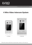
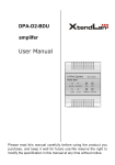
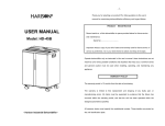
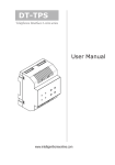
1
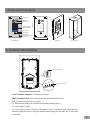
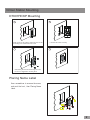
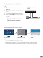
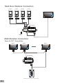
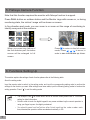
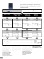
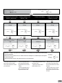
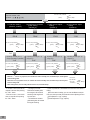
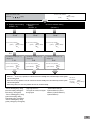
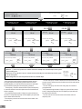
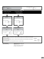
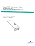
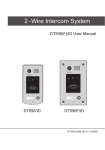
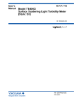
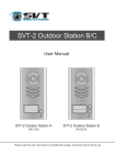
English 2-Wire Video Outdoor Station User Manual 1 2 3 4 5 6 7 8 9 * 0 # DT601FE/KP DT-ENG-601FE/KP-V1 151019 Contents 1.Parts and Functions............................................................................................. 1 2.Terminal Descriptions........................................................................................... 1 3.Door Station Mounting.......................................................................................... 2 4.System Wiring and Connections.......................................................................... 3 5.Fisheye Camera Function.................................................................................... 7 6. Functions Setting Up........................................................................................... 7 7.Unlock Operations................................................................................................ 15 8. Precaustions........................................................................................................ 15 9.Specifications....................................................................................................... 15 10.Cables Requirements......................................................................................... 16 1.Parts and Functions Camera Lens Speaker 1 2 3 4 5 6 7 8 9 * 0 # Touch Sensitive Digital Keypad 220 mm Night Light Nameplate 1 2 3 4 5 6 7 8 9 * 0 # Call Button Microphone Screws for panel mounting DT601FE/KP 120 mm Side View Mounting box 2.Terminal Descriptions 1 2 3 Lock Control Jumper BUS SPL S+ Main Connect Port •• Lock Control Jumper: To select the lock type. •• •• •• •• •• Main Connect Port: To connect the bus line and the electronic locks. BUS: Connect to the bus line, no polarity. PL: External lock power input, connect to the power positive(power +). S+: Lock power(+) output. S-: Lock power(-) output, connect to the power(-) input of locks(only when using the door station to power the locks, if using the external power supply for the locks, the S- will not be connected). -1- 3.Door Station Mounting DT601FE/KP Mounting 1 Drill a hole in the wall to match the size of the mounting box and attach to the wall. 3 2 Connect the cable correctly 4 Attach the panel to the mounting box and use screws supplied to fix the panel Placing Name Label Use a screwdriver to unscrew the screw, and cock the host , then Placing Name Label. AcDbMLeader (ACDB_MLEADER_CLASS) AcDbMLeader (ACDB_MLEADER_CLASS) -2- 4.System Wiring and Connections Basic Connection AC~ PC6 BUS(IM) BUS(DS) DIPS L2 PL S+ S- - 123 ON L1 Doorbell Button + Switch Electric Lock Connection Door Lock Controlled with Internal Power Note: 1 2 3 1. Electronic lock of Power-on-to-unlock type should be used. Jumper position in 2-3 2. The door lock is limited to 12V, and holding current must be less than 250mA. BUS PL S+ S- 3. The door lock control is not timed from Exit Button(EB). 4. The Unlock Mode Parameter of Monitor must be set to 0 (by default). * EB -3 - LOCK Door Lock Controlled with Dry Contact Note: 1. The external power supply must be used according to the lock. Take off the Jumper BUS 2. The inside relay contact is restricted to AC or DC 24V/1A. PL S+ S- 3. The jumper must be taken off before connecting. 4. Setup the Unlock Mode of Monitor for different lock types. POWER SUPPLY •• Power-on-to-unlock type:Unlock Mode=0 (by default) •• Power-off-to-unlock type:Unlock Mode=1 LOCK Unlock parameter setting(set in monitor) INSTALLER SETUP About Local Address 1.Touch icon on main menu page. 123 _ 00.00 Video Standard AUTO System Verson 00.01.00 Display Driver 1.0 Front 1.0 UI 1.0 UNLOCK 2.Touch button and hold for 2s. 3.A digital keypad will be shown. Note: 1.must connect DT601(F)/KP correctly before setting. 2.the parameter will be saved in DT601(F)/KP automatically,so you need only set on one monitor. 3.Here we take DT47M(the monitor) for example, please refer to the corresponding user manual. -4- Multi Door Stations Connection 4# Camera 3# Camera 2# Camera 1# Camera (Device Address:3) (Device Address:2) (Device Address:1) (Device Address:0) L1 L2 PL S+ S- L1 L2 PL S+ S- L1 L2 PL S+ S- L1 L2 PL S+ S- AC~ 100~240VAC A B C D DBC4A PC6 OFF BUS(IM) BUS(DS) ON Impedance switch Multi Monitors Connection Basic IN-OUT Wiring Mode Code=15 Code=14 Code=0 AC~ 100~240VAC PC6 BUS(IM) BUS(DS) 1 2 3 4 5 6 7 8 9 * 0 # (Device Address:0) NOTE:Here we take DT47M(the monitor) for example. -5 - With DBC4A Wiring Mode Code=12 Code=3 Code=2 Code=1 Code=0 A B C D Impedance switch OFF ON DBC4A Code=13 Impedance switch OFF ON DBC4A Code=14 A B C D Code=15 AC~ 100~240VAC PC6 BUS(IM) BUS(DS) 1 2 3 4 5 6 7 8 9 * 0 # (Device Address:0) NOTE:Here we take DT47M(the monitor) for example. -6- 5. Fisheye Camera Function Note that this function requires the monitor with fisheye function to support. Press CALL button on outdoor station and the Monitor rings with screen on, or during monitoring state, the visitors' image will be shown on screen: In five direction pad mode, you can zoom in or zoom out the range of monitoring to identify everyone at the entrance. When you press any lattice of the five direction pad, the lattice screen will be enlarged to full screen. Press to return to the full screen mode; Press , , to move, in order to see individuals up close. 6. Functions Setting Up This section explains the settings of each function,please refer to the following table: About the setting mode: Input the master code to switch to the setting mode, and input the corresponding setting code to perform the settings for the function you want. After settings have been made, input the following setting codes to continue the setting operation. Press " " to exit the setting mode. -7 - •• The example is set as cancel button and # as confirm button,please refer to */# function setting for detail information. •• Forbid to slide to touch the digital keypad,it may cause mistaken key,the correct operation is using your finger to press the digital you desired. •• You should press“confirm”button after finish inputting the code number each time,otherwise,the operation will be canceled automatically in 10s. Order Setting items 1 Reset all settings Setting range Default value Setting code 1234 - 00 1234 01 10 seconds 02 2 Setting the master code 3 Setting the key illumination time 1 ~ 12 digits Valid keys:0 ~ 9 10 to 99 seconds/ continually lit 4 Setting the unlock time 01 to 99 seconds 1 seconds 03 5 Setting the unlock mode 0:opened/1:closed opened 04 6 Operation tone settings 0:on/1:off on 05 7 Reset code settings 1234 - 06 8 &# function settings 0:Normal/1:Reverse Normal 07 9 Call tone settings 0:Enable/1:Disable Enable 08 10 Interference resistant grade settings Valid keys:0 ~ 5 2 09 11 MIC Adjustment Valid keys:0~9 7 10 12 SPK Adjustment Valid keys:0~9 4 11 13 Display Scene Valid keys:0~2 0 12 14 Night Light Level Valid keys:0~5 4 13 15 Device Address Valid keys:0~3 0 14 16 Reserve(not used) Reserve Reserve 15~17 Setting the code forTemporary1 Setting the code forTemporary2 1 ~ 12 digits Valid keys:0~9 1 ~ 12 digits Valid keys:0~9 1 ~ 12 digits Number of codes:40 Valid keys:0~9 1 ~ 12 digits Number of codes:40 Valid keys:0~9 - 18 - 19 - 20~59 - 60~99 17 18 19 Setting the code for user group1 20 Setting the code for user group2 21 Work Mode 0:A partment/1:Villa 1(villa) 100 22 Call Address Valid keys: 0 - 9 00 101 -8- 1 2 3 4 5 6 7 8 9 * 0 # Each operation is indicated by the lighting up of the different color of digital key and nameplate , and by the sounding of the buzzer. The color of key indicator Input the master code. (Default: [ ] +[#] ) 1.Reset all settings (white) 2.Setting the master code (Default 1234) Beep+, Beep 3.Setting the key illumination time (Default 10s) 4.Setting the unlock time (Default 1s) Input the setting code. Input the setting code. Input the setting code. Input the setting code. 00+# 01+# 02+# 03+# The color of key indicator Beep+, Beep (yellow) Inputting of code The color of key indicator (yellow) Inputting of new master code (ex.: 4321)(1~12 digits) 1234+# The color of key indicator (green white) - When the “ Beep+ The color of key indicator Beep+, Beep Inputting of code (ex.: 10) range:00 or 10~99 4321+# The color of key indicator (green white) Beep+ The color of key indicator Beep+, Beep (yellow) (yellow) Inputting of code (ex.: 09) range:01~99 10+# The color of key indicator (green white) Beep+ 09+# The color of key indicator (green * cancel” key is pressed, the indicator will show its standby color, the buzzer beeps, and the system exits the setting mode. - When there isn’t any operation in 10s, the indicator will show its standby color, the buzzer beeps, and the system exits the setting mode. - When setting failure, the color of key indicator will turn red , the buzzer beeps. - All settings will restore to their default value. - When power on or activate the reset all setting item,the keypad checking will carry out, during this time,the key illumination will blink and the touching operation is forbidden, after finish checking,the key illumination will stop blinking and sent out a long sound of beep -9 - - The master code is allowed 1~12 digits,the same code cannot be set for both the user code and the master code,it is recommended that you modify the default master code. - If the key illumination time is set to 00,the key illumination will light up all the time when power on. - If the key illumination time is set to 10~99,the key illumination will light up for 10~99 seconds.At this mode, the key illumination lights off in standby mode, touching any digital key can illuminate,but this is the invalid digital. Beep+, Beep white) Beep+ The color of key indicator (The color of standby) Beep, Beep+ - The unlock time can be set on both monitor and door station, and the valid value is the number you set last time. The color of key indicator Input the master code. (Default: [ ] +[#]) 5.Setting the unlock mode (Default 0(opened)) (white) 6.Setting operation tone (Default ON) Beep+, Beep * 7.Reset code setting 8. &# function setting (Default Normal) Input the setting code. Input the setting code. Input the setting code. Input the setting code. 04+# 05+# 06+# 07+# The color of key indicator The color of key indicator Beep+, Beep (yellow) (yellow) Beep+, Beep Inputting of code 1+# 1+# The color of key indicator The color of key indicator - When the “ Beep+, Beep (yellow) Beep+ (ex.: 1) range:0:(on)/1:(off) (green white) Beep+ Inputting of code 1234+# The color of key indicator (green white) Inputting of code (ex.: 1) range:0:(normal)/1:(reverse) 1+# The color of key indicator Beep+ (green * cancel” key is pressed, the indicator will show its standby color, the buzzer beeps, and the system exits the setting mode. - When there isn’t any operation in 10s, the indicator will show its standby color, the buzzer beeps, and the system exits the setting mode. - When setting failure, the color of key indicator will turn red , the buzzer beeps. - The unlock mode can be set on both monitor and door station, and the valid value is the number you set last time. Beep+, Beep 0/1 (ex.: 1) range:0:(open)/1:(close) white) (yellow) The color of key indicator 0/1 0/1 Inputting of code (green The color of key indicator - When the operation tone is set to 0,pressing the digital keypad will sent out a sound of beep. - When the operation tone is set to 1,pressing the digital keypad will blink one time. - Cancel all the passwords except the master code. - Restore the master code to default value(1,2,3,4) white) Beep+ The color of key indicator (The color of standby) Beep, Beep+ - When the item is set to 0,press the button to cancel the input, * and press the # button to confirm the input. - When the item is set to 1,press the # button to cancel the input, and press the * button to confirm the input . -10- Input the master code. (Default: [ The color of key indicator ] +[#]) 9. Call tone setting (Default enable) Beep+, Beep (white) 10.Interference resistant grade setting (Default 2) 11.IMC volume adjust setting (Default:7) 12.SPK volume adjust setting (Default:4) Input the setting code. Input the setting code. Input the setting code. Input the setting code. 08+# 09+# 10+# 11+# The color of key indicator The color of key indicator The color of key indicator Beep+, Beep (yellow) (yellow) Beep+, Beep (yellow) The color of key indicator Beep+, Beep (yellow) Beep+, Beep 0/1 Inputting of code (ex.: 1) range:0(enable)/1:(disable) 1+# The color of key indicator (green white) - When the “ Beep+ Inputting of code (ex.: 3) range:0~5 3+# The color of key indicator (green white) Beep+ Inputting of code (ex.: 5) range:0~9 5+# The color of key indicator (green white) Beep+ Inputting of code (ex.: 5) range:0~9 5+# The color of key indicator (green * cancel” key is pressed, the indicator will show its standby color, the buzzer beeps, and the system exits the setting mode. - When there isn’t any operation in 10s, the indicator will show its standby color, the buzzer beeps, and the system exits the setting mode. - When setting failure, the color of key indicator will turn red , the buzzer beeps. - If the item is set to 0,the unit will respond a call tone when pressing the “CALL” button. - If the item is set to 1, the unit will have no responds when pressing the “CALL” button. -11- - The larger you set the interference resistant grade, the stronger it will be,but the sensitivity of the keypad will be more lower. - The interference resistant grade setting also will activate the keypad checking. white) Beep+ The color of key indicator (The color of standby) Beep, Beep+ - Unlock via password is still available even when the door station is talking. - When door station is talking, you can enter the Master code (the LED turns white upon that) to activate the volume adjusting function: MIC adjustment: 1 (up), 4 (down); Sleaker adjustment: 3 (up), 6 (down). Input the master code. (Default: [ The color of key indicator ] +[#]) 13. Display scene setting (Default 0) (white) 14.Night light level setting (Default 4) 15.Device address setting (Default:0 ) Input the setting code. Input the setting code. Input the setting code. 12+# 13+# 14+# The color of key indicator The color of key indicator The color of key indicator Beep+, Beep (yellow) (yellow) Beep+, Beep Beep+, Beep (yellow) Beep+, Beep 0/1 Inputting of code (ex.: 1) range:0~2 1+# The color of key indicator (green white) - When the “ Beep+ Inputting of code (ex.: 3) range:0~5 3+# The color of key indicator (green white) Beep+ Inputting of code (ex.: 0) range:0~3 0+# The color of key indicator (green white) Beep+ * cancel” key is pressed, the indicator will show its standby color, the buzzer beeps, and the system exits the setting mode. - When there isn’t any operation in 10s, the indicator will show its standby color, the buzzer beeps, and the system exits the setting mode. - When setting failure, the color of key indicator will turn red , the buzzer beeps. - Scene0: Standby(blue), calling - Night Light Level:0~5. (blue blinks rapidly), talking(blue -The higher the number, the brighter blinks slowly), unlock(green). the night lights. - Scene1: Standby(green), calling (green blinks rapidly), talking (greenblinks slowly), unlock(blue). - Scene2: Standby(blue), calling (yellow), talking(red), unlock(green). The color of key indicator (The color of standby) Beep, Beep+ - Device address Settings: 0(device address:0),1(device address:1),2(device address:2), 3(device address:3). -12- The color of key indicator Input the master code. (Default: [ ]+[#] ) 16.Setting the code forTemporary1 Beep+, Beep (white) 17.Setting the code forTemporary2 18.Setting the code for user group1 19.Setting the code for user group2 20~59 Input the setting code. Input the setting code. 18+# 19+# The color of key indicator Inputting of code (ex.: 1006) 1~12 digits (yellow) white) - When the “ (yellow) (green white) The color of key indicator (yellow) 2012+# The color of key indicator Beep+ (green white) The color of key indicator Beep+ exits the setting mode. - When input the correct temporary password to release the door, the system will clear the temporary password after 60 seconds automatically.But you should know that the password is valid within 60 seconds after inputing the correct temporary password - The temporary1 is used to release the first lock,and the temporary 2 is used to release the second lock(the second lock need external device to support). - If the password length exceeds 12 digits, the system will sent out the sound of “beep,beep,beep,beep”,and the digitals you input before will be cleared at the same time. - The temporary code can not be set the same as the master code and user code. -13- (green * cancel” key is pressed, the indicator will show its standby color, the buzzer beeps, and the system exits the setting mode. - When there isn’t any operation in 10s, the indicator will show its standby color, the buzzer beeps, and the system - When setting failure, the color of key indicator will turn red , the buzzer beeps. Beep+, Beep Inputting of code (ex.: 2012) 1~12 digits 2011+# The color of key indicator Beep+ 60+# Beep+, Beep Inputting of code (ex.: 2011) 1~12 digits 2010+# The color of key indicator (green The color of key indicator Beep+, Beep Inputting of code (ex.: 2011) 1~12 digits 1006+# Input the setting code. (ex.:60) 21+# The color of key indicator Beep+, Beep (yellow) 60~99 Input the setting code. (ex.:21) white) Beep The color of key indicator (The color of standby) Beep, Beep+ - The user code group1 is used to release the first lock,and the user code group2 is used to release the second lock(the second lock need external device to support). - The user code group1 and user code code group2 can contain 40 group passwords - If the password length exceeds 12 digits, the system will sent out the sound of “beep,beep,beep,beep”,and the digitals you input before will be cleared at the same time. - The user code can not be set the same as the master code and temporary code. The color of key indicator Input the master code. (Default: [ ]+[#] ) 20.Work mode setting (Default:1/villa) Input the setting code. (white) 21.Call address setting (Default:villa:00,16; a partment:00~31) Input the setting code. 100+# 101+# The color of key indicator The color of key indicator Beep+, Beep (yellow) Inputting of code (ex.: 1) range:0(a partment)/1:(villa) (yellow) 0+# The color of key indicator white) - When the “ Beep+, Beep Inputting of code (ex.: 1) range:Valid keys: 0 - 9 0+# (green Beep+, Beep The color of key indicator Beep+ (green white) Beep+ * cancel” key is pressed, the indicator will show its standby color, the buzzer beeps, and the system exits the setting mode. - When there isn’t any operation in 10s, the indicator will show its standby color, the buzzer beeps, and the system exits the setting mode. - When setting failure, the color of key indicator will turn red , the buzzer beeps. - Work mode setting: 0(a partment)/1:(villa). The color of key indicator (The color of standby) Beep, Beep+ - When the work mode is villa,the call address:00 or 16. - When the work mode is a partment, the range of call address:00~31. -14- 7.Unlock Operations Unlocking of user code When the registered user code has been input using the keypad (1~12 digits), the LED background indicator lights up, the buzzer sounds,and the electric door strike is unlocked.(note that you should press "#" button(if "#" button is set to confirm button) after input the unlock code) •• The time interval during which the button must be pressed is approximately 10 seconds. If the time interval exceeds approximately 10 seconds, the input value will be cleared. •• If you make a mistake when inputting the user code,press the" cancel" button and input the user code again. •• The release function is forbidden and the input operation is disabled for 60 seconds if 10 times incorrect access codes are continuously attempted. During this time,the buzzer will continuously sound about 8 times. 1. During calling,pressing "cancel" button can cancel the calling 2. If input the incorrect access code,the buzzer will sound of beep,beep,beep 8. Precaustions •• Please clean the unit with soft cotton cloth, don't use the organic impregnant or chemical clean agent. If necessary, please use a little pure water or dilute soap water to clean the dust. •• The unit is weather resistant. However do not spray high pressure water on access control keypad directly. Excessive moisture may cause problems with the unit. •• You must use the right adaptor which is supplied by the manufacture or approved by the manufacture.. •• Pay attention to the high voltage inside the products, please refer service only to a trained and qualified professional. 9.Specifications •• •• •• •• •• •• •• •• •• -15- Power Supply : DC 24V ; Power Consumption: Standby 40mA; Working status 160mA; Camera: Color ARS; 420 TV Lines; Unlocking time: 1~99s Lock Power supply: 12Vdc, 280mA(Internal Power); Number of relay circuits: 2(the second lock need external device to support) Mounting: Flush mounting Working temperature: -15ºC ~ +55ºC Dimension:220(H)×120(W)×50(D)mm 10.Cables Requirements The maximum distance of the wiring is limited in the DT system. Using different cables may also affect the maximum distance which the system can reach. The farest monitor monitor with two or four monitors monitor monitor DBC4A B C AC~ 100~240VAC When Monitor quantity < 20 Cable Usage A PC6 B C BUS(IM) BUS(DS) Twisted cable 2x0.75 mm 2 Twisted cable 2x1 mm2 60 60 30 80 80 40 A When Monitor quantity > 20 Cable Usage A B C Twisted cable 2x1 mm2 70 30 20 Twisted cable 2x1.5 mm2 70 50 30 1 2 3 4 5 6 7 8 9 * 0 # Note:If the monitor has been specified the distance,refer to the parameter. -16- The design and specifications can be modified without notice to the user. Right to interpret and copyright of this manual are reserved. DT-ENG-601FE/KP-V1 151019