1
1991 CAPRI SHOPMANUAL FPS-12186-91
Copyright © 1990, Ford Motor Co.
Litho in U.S.A.
March,1990
www.techcapri.com
Page Blank In Original Document
Copyright © 1990, Ford Motor Co.
www.techcapri.com
Important safety Notice Appropriate service methods and proper repair procedures are essential
for the safe, reliable operation of all motor vehicles as well as the per
sonal safety Of the Individual doing the work. This Shop Manual provides
general directions for accomplishing service and repair work with tested,
effective techniQues. Following them will help assure reliability.
There are numerous variations In procedures, techniQues, tools, and
parts for servicing vehicles, as well as In the skill of the Individual dOing
the work. This Manual cannot POSSibly anticipate all such variations and
provide advice or cautions as to each. AcCordingly, anyone who departs
from the instructions provided In this Manual must first establish that he
compromises neither his personal safety nor the vehicle integrity by his
choice of methods, tools or parts.
Notes, cautions, and warnings AS you read through the procedures, you will come across NOTES, CAU
TIONS, and WARNINGS. Each one Is there for a specific purpose. NOTES give
you added information that will help you to complete a particular proce
dure. CAUTIONS are given to prevent you from making an error that could
damage the vehicle. WARNINGS remind you to be especially careful In
those areas where carelessness can cause personal Injury. The following
list contains some general WARNINGS that you should follow when you
work on a vehicle.
• Always wear safety glasses for eye protection.
• Use safety stands whenever a procedure reQuIres you to be under the
vehicle.
• Be sure that the Ignition switch Is always In the OFF position, unless
otherwise reQuired by the procedure.
• Set the parking brake when working on the vehIcle. If you have an
automatic transmission, set It In PARK unless Instructed otherwise for a
specific operatIon. If you have a manual transmission, It should be in
REVERSE (engine OFF) or NEUTRAL (engine ON) unless Instructed other
wise for a specific operation. Place wood blocks (4" x 4" or larger) to
the front and rear surfaces of the tires to provIde further restraint
from inadvertent vehicle movement.
• Operate the engine only In a well-ventilated area to avoid the danger
of carbon monoxide.
• Keep yourself and your Clothing away from moving parts, when the
engine is running, especially the fan and belts.
• To prevent serious burns, avoid contact with hot metal parts such as
the radiator, exhaust manifold, tall pipe, catalytiC converter and mUf
fler.
• Do not smoke while working on a vehicle.
• To avoid injury, always remove rings, watches, loose hanging jewelry,
and loose clothing before beginning to work on a vehicle.
• If it is necessary to work under the hOOd, keep hands and other objects
clear of the radiator fan blades! The electrIc cooling fan can start to
operate any time by an increase In underhood temperature, but only
when the ignitIon swItch is in the RUN positIon. For thIs reason care
should be taken to ensure that the electriC cooling fan motor Is com·
pletely disconnected when working under the hood when engine Is
Copyrightnot
© 1990,
Ford Motor Co.
running.
www.techcapri.com
Page Blank In Original Document
Copyright © 1990, Ford Motor Co.
www.techcapri.com
Foreword ThiS 1991 Car Shop Manual provides information covering normal service,
repairs, and maintenance for Body, Chassis, Electrical, powertrain, Mainte
nance and Lubrication systems for 1991 Capri passenger cars manufac
tured in Australia.
This manual is organized into Groups covering general systems. Within
each Group, the information is further divided into Sections. There is one
Section for each component or sub-system. Some Groups contain a Ser
vice Section to cover procedures common to several components or sub
systems within the Group. In general, each Section contains the
Description, Operation, Diagnosis and Testing, Removal and Installation,
and Disassembly and Assembly procedures for the component covered in
the Section. Diagnosis Charts are also included in some Sections to help
you systematically locate and correct problems encountered. In most
cases, specifications are included at the end of each Section.
To aid in locating specific subjects in this manual, use the Table of Con
tents on the following pages, or the Alphabetical Subject Index in the
back of this manual.
AS a further aid, there is an index on the first page of each Group which
lists the Section title and Section number for each component covered
within the group. The first page of each Section also contains an index to
locate service operations covered in that Section. This Group-Section
breakdown is also indicated in the page number located at the top of
each page.
Example: 11·02-3 = (Group) 11 - (Section) 02 - (page) 3
The descriptions and specifications contained in this manual were in
effect at the time this manual was approved for printing. Ford Motor
Company reserves the right to discontinue models at any time, or change
specifications or design without notice and without incurring obligation.
~tr\Jltt
~ublitation5
Copyright © 1990, Ford Motor Co.
Ford Parts and Service DIVISion
Copyright © 1990, Ford Motor Company
www.techcapri.com
Page Blank In Original Document
Copyright © 1990, Ford Motor Co.
www.techcapri.com
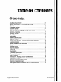
Table of Contents
Group Index
Auxiliary Equipment ....................................35 Body Shell, Exterior Trim and Underbody ..................47 Brakes ................................................12 Charging system .......................................31 Cooling System ........................................27 Doors, Hood and Luggage compartment Door ..............44 Engines, Gasoline .......................................21 Exhaust System ........................................26 Fuel System ...........................................24 Halfshafts ... . . . . . . . . . . . ...............................15 Identification Codes ....................................10 Ignition System ........................................23 Instrument Clusters, Controls and warning systems .........33 Lighting system ........................................32 NOise, Vibration and Harshness ...........................18 Seats ..................................... , ...........41 Speed Control .........................................37 Starting System ........................................28 Steering ..............................................13 suspension ............................................14 Transaxle, Automatic ....................................17 Transaxle, Manual ......................................16 Trim, Interior ..........................................45 ventilating, Heating and Air Conditioning ..................36 Wheels and Tires .......................................11 Window Glass and Mechanisms ...........................42 Window Glass, Stationary ................................43 Wiring Harnesses, Connectors and Circuit protection ........34 Copyright © 1990, Ford Motor Co.
www.techcapri.com
-Page Blank In Original Document
Copyright © 1990, Ford Motor Co.
www.techcapri.com
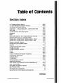
Table of contents Section Index A/C-Heater System, Manual ............................36-41 AIC and Refrigerant System-service ...................36-32 Air Cleaner and Duct Systems ..........................24-41 Alternator - Integral Regulator-External Fan TYpe .......31-17 Antennas ...........................................35-10 Ash Receptacles and Cigar Lighter ......................35-40 Batteries ...........................................31-02 Body ..............................................47-02 Body Shell, Exterior Trim and underbody-Service ........47-01 Brake Booster, vacuum-Dash Mounted .................12-50 Brakes, Disc-Single Piston, Sliding Caliper-Front .........12-20 Brakes, Disc-Single Piston, Sliding Caliper-Rear ..........12-25 Brakes, Hydraulic-service .............................12-01 By-pass Air Control (BPA) System ...........................9 Carpets ............................................45-26 Catalyst and Exhaust System ..............................6 Charge Indicator .....................................33-32 charging System-Service .............................31-01 Clock ...............................................33-15 Clutch ..............................................16-02 Clutch and Manual Transaxle-Diagnosis .................16-01 Compressor and Clutch ...............................36-39 console, Floor .......................................45-31 Convertible .........................................47-07 Cooling System-Service ..............................27-01 Diagnostic Routines .....................................2 Door-Hinge, Latch, Manual Lock and weatherstrip .........44-06 Door Locks, Power ...................................44-16 Drive Belts, Accessory-Service ........................27-02 EEC Pinpoint Tests ......................................16 EEC Quick Test-All Engines ..............................15 EEC-IV Monitor Intermittent Fault Diagnosis ................17 Continued
Copyright © 1990, Ford Motor Co.
www.techcapri.com
Page Blank In Original Document
Copyright © 1990, Ford Motor Co.
www.techcapri.com
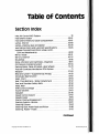
Table of Contents Section Index
Emission Control Identification I Application .................1 Emission System Description, operation and Component location ..................................3 Engine Coolant Temperature Indicating System ..........33-25 Engine, Gasoline-Service .............................21-01 Engine, 1.6l ........................................ .21-10 Engine Supplement .....................................4 Evaporative Emission (EVAP) System ........................8 Exhaust Gas Recirculation (EGR) System .....................7 Exhaust System-service ..............................26-01 Fan, Electro-Drive Cooling ............................ .27-10 Fuel Delivery Systems ...................................13 Fuel Filters ..........................................24-51 Fuel Injection, Electronic ............................. .24-05 Fuel level Indicating System .......................... .33-20 Fuel Pump-Electric ..................................24-35 Fuel system-Service .................................24-01 Fuel Tanks and lines ................................. .24-50 Fuses and Circuit Breakers ............................ .34-50 Glass, Stationary-Windshield ......................... .43-02 Halfshafts and CV JOints-Front Wheel Drive .............15-22 Hardtop, Removable ................................. .47-10 Headlamp System .................................. .32-02 Heater and power Ventilation System .................. .36-10 Heating System-service ..............................36·01 Hoisting, JaCking and Towing ..........................10-04 Hood, Hinge and latch .............................. .44-08 Horns ............................................. .35·80 Identification Codes ..................................10-01 Ignition Switch ..................................... .31-20 Ignition system and Timing procedures ....................14 Ignition System Service .............................. .23-03 Continued Copyright © 1990, Ford Motor Co.
www.techcapri.com
Page Blank In Original Document
Copyright © 1990, Ford Motor Co.
www.techcapri.com
Table of contents Section Index Inlet Air Control (lAC) System .............................10 Instrument Cluster ...................................33-Q1 Instrument panel and Glove compartment ..............45-61 lamps, Interior ......................................32-60 lamps-parking, Rear and Marker ......................32-20 lubrication pOints and lubricant Specifications ...........10-03 luggage Compartment-Door; Hinge, latch, lock and weatherstrip ..............................44-10 Mirror; Inside ........................................42-21 Mirrors, Exterior .....................................42-25 Mouldings ..........................................45-16 Noise, Vibration and Harshness-Diagnosis ...............18-01 Oil Pressure Indicating System .........................33-34 Parking Brake, Cable Actuated-Rear Wheels .............12-70 Positive Crankcase Ventilation (PCv) System .................11 Radiator ............................................27-03 Restraint System-Supplemental Air Bag ................41-58 Scheduled Maintenance ..............................10-02 Seats, Front ............................'.............41-04 seat, Crlild Restraint-Tether Attachment ................41-52 Seat and Shoulder Safety Belts .........................41-50 seats, Rear ..........................................41-20 Shift Control linkage .................................17-02 Sound Systems ......................................35-01 speakers ...........................................35-30 Speed Control System ................................37-01 Speedometer .......................................33-10 Starter; Positive Engagement ..........................28-02 Starting System-service ..............................28-01 Steering Column .....................................13-04 Steering Gear; Power Rack-and-Pinion ...................13-46 Steering, power-Hoses ...............................13-55 continued Copyright © 1990, Ford Motor Co.
www.techcapri.com
Page Blank In Original Document
Copyright © 1990, Ford Motor Co.
www.techcapri.com
Table of Contents Section Index Steering Pump, Power ................................13-51 Steering-Service ....................................13-01 suspension, Front ....................................14-10 Suspension, Rear .....................................14-32 Suspension-Service ..................................14-01 Tachometer .........................................33-11 Throttle linkage .....................................24-60 Transaxle, Automatic 4EAT .............................17-27 Transaxle, Automatic-Service .........................17-01 Transaxle, Manual 5-Speed-Non-Turbo Engine ...........16-37 Transaxle, Manual 5-Speed-Turbo Engine ...............16-38 Trim panels, Interior ..................................45-03 Turbo Boost Indicating System .........................33-36 Turbocharger .......................................24-45 Turbocharger System ...................................12 Turn Signal and Hazard Flasher .........................32-40 warning Indicators ...................................33-45 Wheel Hubs and Bearings-Front .......................11-10 Wheel Hubs and Bearings-Rear ........................11-15 Wheels and Tires-Service .............................11-01 Window Glass and Mechanisms-Service .................42-01 Window, Rear-Defroster .............................36-86 Windows, Power .....................................42-08 Windshield washers ..................................35-70 Windshield Wipers ...................................35-60 wiring Harness-Connectors ...........................34-01 wiring Harnesses ....................................34-26 Copyright © 1990, Ford Motor Co.
www.techcapri.com
Page Blank In Original Document
Copyright © 1990, Ford Motor Co.
www.techcapri.com
10-01-1
GROUP
IDENTIFICATION
CODES
SECTION TITLE
PAGE
HOISTING, JACKING AND TOWING ..•.......•.....•.••........ 10-04-1
IDENTIFICATION CODES ......•.•.....•.......••..............•.•.. 10·01-1
10
SECTION TITLE
PAGE
LUBRICATION POINTS AND LUBRICANT SPECIFICATIONS ....••...............••......••...•.•.••....•••.... 10-03-1 SCHEDULED MAINTENANCE ..................................... 10-02-1 SECTION 10-01 Identification Codes SUBJECT
PAGE
DESCRIPTION
Official Vehicle Identification Number .................... 10-01-1
Vehicle Build Date .................................................. 10-01-4
SUBJEC r
PAGE
DESCRIPTION (Cont'd.)
Vehicle Certification Label ..................................... 10·01-2
VEHICLE APPLICATION ............................................. 10-01-1
VEHICLE APPLICATION
Capri.
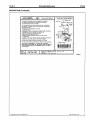
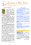
DESCRIPTION Official Vehicle Identification Number
The official Vehicle Identification Number (VIN) is
stamped on a metal tab that is fastened to the
instrument panel close to the windshield on the driver's
side of the vehicle. The VIN is 17 digits long and is
visible from outside the vehicle.
The VIN is used for title and registration purposes and
for warranty identification. The VIN indicates the
manufacturer, type of restraint system, vehicle line,
series, body type, engine, model year, assembly plant
and production serial number. The serial number of
each unit built is shown as the last six digits of the VIN.
c
r
~
BODY 6
4
TYPE 01 = BASE 02
= XR2
SOURCE
CODE
T = BUILT
OUTSIDE NORTH
AMERICA
RESTRAINT
SYSTEM TYPE
C = ACTIVE BELTS
PLUS DRIVER SIDE
AIR BAG
~';l~
\ SERIAL NUMBER
ASSEMBLY PLANT
8 BROAD
MEADOWS
AUSTRALIA
MODEL YEAR
M = 1991
ENGINE
6 = 1.6L EFI TC
Z = 1.6L EFI DOHC
WORLD MANUFACTURER
6MP = FORD OF
AUSTRALIA
Y4125·A
Copyright © 1990, Ford Motor Co.
www.techcapri.com
Identification Codes
10-01-2 DESCRIPTION (Continued)
The Vehicle Certification Label also contains a 17
character Vehicle Identification Number (VIN). This
number is used for warranty identification of the
vehicle and indicates: manufacturer, type of restraint
system, vehicle line, model series, body type, engine,
model year, and consecutive unit number.
The remaining information on the Vehicle Certification
Label consists of the following vehicle identification
codes: exterior color, body type, convertible roof
color, interior trim type and color, radio type, axle
ratio, and transmission type.
The following charts provide various codes and their
respective identification.
Vehicle Certification Label
The Vehicle Certification Label is affixed to the left
hand door jamb below the latch striker. The upper half
of the label contains the name of the manufacturer,
month and year of manufacture, Gross Vehicle Weight
Rating (GVWR), Gross Axle Weight Rating (GAWR),
and the certification statement.
MANF. BY FORD MOTOR COMPANY OF AUSTRALIA LIMITED
MADE IN AUSTRALIA
PRODUCTION MONTHIYEAR - - - - - - - - " " " DATE:
3Il1O
QVWR: FRONTQAWR: REARQAWR: THIS VEHICLE CONFORMS TO AU APPIJCA/II.f FEDERAL MOTOR
VEHICLE SAFETY, BUMPER AND THEFT PREVENTION STANDARDS
IN EFFECT ON THE DATE OF MANUFACTURE SHOWN ABOVE.
VEHICLE IDENTIFICATION NUMBER------_~
EXTERIOR PAINT COLOR CODE
BODY TYPE CODE
VIN -
TYPE -
:fEROt
-----------......1
IODV
8H
j
j
Pl\Htf CODES
TVA i
DBO
MlOG , tNt TRIM i rAPE i R I S
Ill!
A
H
A:,t fA
4
W
t
CONVERTIBLE ROOF TYPE AND COLOR CODE _ _ _ _ _ _..J
INTERIOR TRIM CODe
RADIO TYPE CODe _ _ _ _ _ _ _ _ _ _ _ _ _ _ _ _ _ _ _ _--.J
AXLERATIOCODE _ _ _ _ _ _ _ _ _ _ _ _ _ _ _ _ _ _ _ _ _ _ _ _ _ _ _ _ _
~
TRANSMISSION CODE - - - - - - - - - - - - - - - - - - - - -_____________..J
WORLD MANUFACTURER IDENTIFER
RESTRAINT SYSTEM TYPE
(VIN POSITION 4)
(yIN POSITIONS 1, 2 AND 3)
~
CV4OO1-A
CT01Z4MB600001
VINCode
lllnufllclurer
MI.
l\'pt
SUP
Ford Motor Company
of Austral ia, LTD
Mercury
Passenger Car
VINCode
C
Active Belts and Driver Air Bag
CV4003-A
CV4002·A
FORD PASSENGER CAR IDENTIFIERS
(VIN POSITION 5)
6MPC T O1Z4M8600001
VIN Code
T
Copyright © 1990, Ford Motor Co.
De,lgnation
All Passenger Cars Imported from Outside North
Aimerica or Non-Ford Buill Passenger Cars Marketed
by Ford in North Aimerica
CV4004·A
www.techcapri.com
10-01-3
Identification Codes
10-01-3
DESCRIPTION (Continued)
LINE, SERIES, BODY TYPE FOR PASSENGER CARS
(YIN POSITION 6 AND 7)
6MPCT
I!!l Z4M8600001
VIN Code
Line
Series
Body1\tpe
Body Code
01
03
Mercury
Merciry
Capri
Capri XR2
2 Dr. Convertible
2 Dr. Convertible
BH
FF
C'i4005-A
ENGINE CODES
(VIN POSITION 8)
6MPCT01
00 4M8600001
Displacement
VINCode
Z
6
Liter
CID
Cyllndeta
Fuel
Manufacturer
1.6 DOHC EFI
1.6 DOHC EFI Turbo
98
98
4
4
Gasoline
Gasoline
Mazda
Mazda
I
C'i4006-A
PRODUCTION SEOUENCE NUMBER
(YIN POSITIONS 12 THROUGH 17)
CHECK DIGIT FOR ALL VEHICLES
(YIN POSITION 9)
6MPCT01Z
6MPCT01Z4M8
c!J M86~01
Sales Division
Lincoln MerCury Division
CY401O-A
Sequence Number
CV4007·A
600,001 Through 999,999
VEHICLE MODEL YEAR
(VIN POSITION 10)
6MPCT01Z4
EXTERIOR/INTERIOR COLOR CHART
8600001
fA
EXTERIOR PAINT COLORS
VINCoda
Model"ar
1991
M
BODV
CY4008·A
VIN Code
8
TVR
MLDG.
. Po,ar While
i I~Clgo Blue CIC Me:
P:al,num CIC MeL
Dark Charcoal
III 600001
I
Aeeembly Plant
INT.
TRIM
DE
A
I Exterior
Paint Color
I Cardinal Red
ASSEMBLY PLANT CODE (VIN POSITION 11) 6MPCTOI Z4M
BH
I I I
Inlerior Trim
! Paint
Code
Gray Cloth
!
EA
I
YA
DE
DE
DE
DE
DE
I
EB
VB
W3
w
H
Red Cloth
-
D3
I
D3
03
CV4011·A
Broadmeadows. Auslralia
CY4009·A
Copyright © 1990, Ford Motor Co.
www.techcapri.com
Identification Codes
10-01-4
10-01-4
DESCRIPTION (Continued)
BODY TYPE CODES
RADIO TYPE CODES
EA
EXTERIOR PAINT COLORS
BODY
I I
BH
A
TVR
I
MLDG.
EA
EXTERIOR PAINT COLORS
INt
TRIM
ITAPEIRISIAXI
DE
H
W
4
BH
VIN
Code
Line
01
03
Mercury
Mercury
BH
FF
Serlea
Capri
Capri XR2
A
Body~pe
Code
2 Dr. Convenible
2 Dr, Conll8nible
Y
DE
W
4
I
Redlo ~pe
Radio Delete
AMIFM Electronic
AM/FM Electronic with Cassette
AMIFM Premium Sound with Cassette
F
H
6
CY4012-A
~
TR
I
CY4015·A
CONVERTIBLE ROOF TYPE AND COLOR IDENTIFICATION
EA
EXTERIOR PAINT COLORS
BODY
BH
AXLE RATIO CODES
I I I
TVR
MLOG.
EA
EXTERIOR PAINT COLORS
INt
TRIM
~
DE
H
4
W
BODY
I I
BH
A
DE
Code
Axle Ratio
TVR
MLDG.
I
INt
TRIM
H
4
W
Convertible Roof Color
Code
White
Black
W
A
4.10 WIDOHC EFt MTX
3,85 W/DOHC EFI Turbo MTX
3.45 WIDOHC EFI ATX
4
D
B
CY4013-A
CY4016·A
INTERIOR TRIM CODES
EA
EXTERIOR PAINT COLORS
BODY
BH
I I I
TVR
MLOG.
A
~ Code
111m CoIor~pe
Gray Cloth
DE
D3
TRANSMISSION CODES
INt
TRIM
H
4
W
EA
EXTERIOR PAINT COLORS
BH
Red Cloth
CY4OM-A
A
Code
W
W
A
DE
H
4
U71
lIansml88ton lYpe
5 Speed Manuat - 1,ElL DOHC EFI
5 Speed Manual 1,6L DOHC EFI Turbo
4 Speed Automatic Transaxle - 4EAT
CY4017-A
Vehicle Build Date
The build date is stamped on the driver's side strut
tower in the engine compartment. The numbers are
approximately Bmm high in red or yellow ink. The build
date is a four digit code which shows the month then
the date but not the year. The year is shown in the VIN.
For example:
0509 = May 9th
1201 = December 1st
Copyright © 1990, Ford Motor Co.
www.techcapri.com
10-01-5
Identification Codes
10-01-5
DESCRIPTION (Continued)
Copyright © 1990, Ford Motor Co.
www.techcapri.com
10-02-1
Scheduled Maintenance
10-02-1
SECTION 10-02 Scheduled Maintenance SUBJECT
PAGE
DESCRIPTION
Maintenance Schedules ......................................... 10-02·3
Vehicle Emission Control Information
Decal ................................................................. 10-02·1
SUBJECT
PAGE
VEHICLE APPLICATION ............................................. 10-02-1
VEHICLE APPLICATION
Capri.
DESCRIPTION The Maintenance Schedule lists the items required to
maintain the vehicle emission systems at levels
determined by the Federal Government
(Environmental Protection Agency). Following is an
index to a number of Maintenance Procedures, each of
which is related to an item listed on the maintenance
schedule. Use these procedures to perform the
required emission system maintenance items listed on
the maintenance schedules.
MAINTENANCE PROCEDURE INDEX
PROceDURE
i
Maintenance service adjustments must conform to
specifications contained here, listed in the
Specifications Manual or shown on the Vehicle
Emission Control Information Decal, or the emissions
system may become inoperative.
WARNING: Before starting the engine to perform
maintenance, ensure the transaxle selector is in
the PARK position (automatic transaxle), or the
NEUTRAL position (manual transaxle), the
parking brake is set and the wheels are blocked.
MANUAL AND SECTION
I Engine Mechanical Sub-Systems
• Change Engine Oil and/or Filter
• Coolant Condition and Protection
• Cooling System Check and Coolant Replacement
• Drive Belt Condition and Tension
• Air Cleaner and/or Crankcase Filter
Group 21, Engine, Gasoline Service
Section 27-01, Cooling System Service
Section 27-01, Cooling System Service
Section 27-02, Drive Belts, Accessory Service
Section 24-41, Air Cleaner and Duct Systems
II Ignition Sub·Systems
• Spark Plug Replacement
Section 23-03. Ignition System Service
III Fuel System
• Engine Idle Speed Adjustment
Refer to Capri Engine/Emissions Dlagnosis
CA13139·A
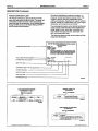
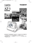
Vehicle Emission Control Information Decal
Vacuum hoses on the engine use a color stripe to aid in
hose routing checks. The stripe will usually be the
same color as on the Vehicle Emission Control
Information (VECI) decal, but the correct vacuum hose
routing must be verified by using the correct
component connections shown on the VECI decal.
Copyright © 1990, Ford Motor Co.
www.techcapri.com
Scheduled Maintenance
10-02-2
10-02-2
DESCRIPTION (Continued)
VEHICLE EMISSION
CONTROL INFORMATION
~
FORD MOTOR COMPANY
VACUUM HOSE ROUTING DIAGRAM
s:
UT II CHECK VALVE
TH~S VEHICLE IS EQUIPPED W~TH ELECTROt>lIC FUEL It>lJECTIOt>l
IDLE MIXTURE. COLD ENGINE IDLE SPEED AND. COLD Et>lGINE
FUEL ENRICHMENT ARE t>lOT ADJUSTABLE
2 WAY VALVE)
••
SET PARKIt>lG BRAKE AND BLOCK WHEELS. MME ALL ADJUSTMENTS
WITH ENGINE AT NORMAL OPERATING TEMPERATURE ACCESSORIES
AND HEADLIGHTS OFF
IGt>lITION TIMING-TRAt>lSMISSIOt>l IN NEUTRAL (II TURN OFF ENGINE {21 DISCONNECT THE WHITE ELECTRICAL CONNECTOR ON DISTRIBUTOR. (3, DISCONNECT AND PLUG DISTRIBUTOR VACUUM LINE. (4) RE·START PREVIOUSLY WARMED-UP ENGINE
(5) ADJUST IGNITION TIMING TO 2' BTDC.
(6) TURN OFF ENGIt>le. RECONNECT ELECTRICAL AND VACUUM
CONNECTIONS
-fROM fUEl TANK
~
UTY
-B
I ••••••••
CAN
VALVE
•
J WAY SV:?1
_..r-
SOlENOID
r···
•1
I
---i."-__ I
•
••
t
IN
MANF
IDLE SPEED - WITH SHIFT LEVER IN NEUTRAL FOR MANUAL TRANS AND
IN PARK FOR AUTO TRAt>lS ADJUST IDLE SPEED TO 8S0RPM
BY PASS ADJUST SCREW IS PRESET AND SEALED AT FACTORY.
FOR DETAILED MAINTENANCE INFORMATION. REFER TO SERVICE MANUAL
THIS VEHICLE CONFORMS TO u.S. EPA AND CALIFORNIA
REGULATIONS APPLICABLE TO 1991 MODEL YEAR NEW MOTOR
VEHICLES INTRODUCED INTO COMMERCE SOLELY FOR SALE
IN CALIFORNIA
, fRONT OF VEHICLE
: -Illil':ll!~I'!mllm:II[II~~~,i-1
L_':"~~I_6
9OJA·
9C<ss-CB
CATALYST
v:
~y C A:
SPARK PLUG ~ GAP .039"·043" (1.0· 11mm)
1.8L·1HA
MFM1.6VSFYC2 (TWC SMPI 02S;
A14341).A
Copyright © 1990, Ford Motor Co.
www.techcapri.com
Scheduled Maintenance 10-02-3
DESCRIPTION (Continued)
Maintenance Schedules
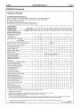
CUSTOMER MAINTENANCE SCHEDULE A Follow this Schedule if your driving habits MAINLY include one or more of the following conditions: • Short trips of less than 10 miles (16 km) when outside temperatures remain below freezing.
• Operating in severe dust conditions.
• Operating during hot weather, in stop-and-go "rush hour" traffic.
• Extensive idling, such as police, taxi or door-to-door delivery service.
I3
9
12
Kilometers x 1000 4.8 9.6 14
19
Miles x 1000
I
I I
I
I SERVICE INTERVAL
Perform at the months
or distances shown, whichever comes first.
6
i
:
15
18
24
28 33
I
I
I
i
:
:
21 : 24 127 30 33
38
43
48
52
I
I
i
36 39142 145 48
51
54
57
81
86
62
67
72
76
I 57 60
91
96
EMISSION CONTROL SERVICE
I
IChange Engine Oil and Oil Filter
i
I
I (whichever occurs hrst)
Every 3 Months or
I
X
X
X
I Replace Spark Plugs: Turbocharged
X
X
X
Jx
~
X
I
X
i
i
I
I
I
X X
X IX
I
Ix
X
X
X
X
X
X
i
X
X
Non-Turbocharged
X
ANNUALLY
Check Engine Coolant Protection, Hoses and Clamps Replace Engine Coolant Every 36 Months or
, Check Accessory Drive Belts
X
X
X
X
i
X:2
X®
Inspect Air Cleaner Filter
i
Xu)
Replace Air Cleaner Element
XI
X
Replace Fuel Filter
EVERY 60,000 MILES (96,000 km)
•Replace Engine Timing Belt ! Check Engine Idle Speed
X:[
X®
GENERAL MAINTENANCE
Rotate Tires
IX
X
X
X
,
X
X
Inspect Brake Lines, Connections & Hoses
X
•Inspect Clutch Pedal Operation
, Inspect Front and Rear DISC Brakes
X
i Inspect Safety Belts. Buckles,
X
X
X
X
!
i
Retractors & Anchors
I
Inspect Steering Lmkage,
I Rack Guides &Tie Rod Ends
!
X
I
i
Ix
i
I
X
X
'X
Tighlen Bolts &Nuts on Chassis & Body
X
I
I Inspect Steering Operations,
Gear Housing and Rack Seal Boots
I
X
I Inspect Front Suspension Ball Joints I
X
i
Inspect Half Shaft Dust Boots
, Inspect Exhaust System Heat Shield I
i
X
X
X
X
X
X
X
l
Inspect Fuel Lines
X
, Lubricate Rear Wheel Bearings
X
.}
Change Automatic Transaxle FlUid
1
If operating in severe dusty conditions, consult dealer for proper replacement interval. Recommended. but not required. Change automatic transaxle flUid if your driVing habits frequently include one or more of the following conditions: • Operation during hot weather (above 90°F, 32 C C), carrying heavy loads and in hilly terrain.
• Police. taxi or door-to-door delivery service
4 This item not required to be performed, however, Ford recommends that you perform maintenance on this item in order to achieve best vehicle operation. Failure :0 perform this recommended maintenance will not invalidate the vehicle emissions warranty or manufacturer recall liability. This maintenance
IS
required
In
all states except California However. we recommend that it aiso be performed on California vehicles.
Copyright © 1990, Ford Motor Co.
CA13140·A
www.techcapri.com
i
10-02-4
10-02-4
Scheduled Maintenance DESCRIPTION (Continued)
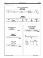
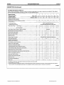
CUSTOMER MAINTENANCE SCHEDULE B
Follow maintenance Schedule B if, generally, you drive your vehicle on a daily basis for more than 10 miles (16 km) and NONE OF THE UNIQUE
DRIVING CONDITIONS SHOWN IN SCHEDULE A APPLY TO YOUR DRIVING HABITS.
SERVICE INTERVAL
Perform at the months
or distances shown,
whichever comes first.
Miles x 1000
7.5
15
22.5
30
37.5
45
52.5
60
x 1000
12
24
36
48
60
72
84
96
X
X
X
X
X
X
X
X
Kilometers
EMISSION CONTROL SERVICE
Change Engine Oil & Filter (whichever occurs first)
Every 6 Months or
Turbocharged Vehicles
Replace Engine Oil & Filler
Replace Spark Plugs:
EVERY 5,000 MILES (8,000 KM)
OR 6 MONTHS WHICHEVER OCCURS FIRST
Turbocharged
X
Ql
X
Ql
I
X
X
Non-Turbocharged
I
Check Engine Coolant Protection, Hoses and Clamps
ANNUALLY
Replace Engine Coolant Every 36 Months or
X
X
Check Accessory Drive Belts
X
X
Replace Air Cleaner Element
XeD
XeD
Replace Fuel Filter
X
Replace Engine Timing Belt
REPLACE EVERY 60,000 MILES (96,000 km)
XI}:
XI}:
Inspect Brake Lines and Connections
X
X
Inspect Clutch Pedal Operation
X
X
Check Engine Idle Speed
GENERAL MAINTENANCE
Inspect Front and Rear Disc Brakes
X
X
X
X
Inspect Safety Belts, Buckles, Retractors & Anchors
X
X
Inspect Steering Linkage, Rack Guides & Tie Rod Ends
X
X
Tighten Bolts & Nuts on Chassis & Body
X
X
Inspect Steering Operations, Gear Housing and Rack Seal Boots
X
X
Inspect Front Suspension Ball Joints
X
X
Inspect Half Shaft Dust Boots
X
X
Inspect Exhaust System Heat Shield
X
X
Inspect Fuel Lines
@
X
Lubricate Rear Wheel Bearings
X
X
Rotate Tires
X
X
X
I
X
If operating in severe dust, more frequent intervals may be required. Consult your dealer.
but not required.
This item not required to be performed, however, Ford recommends that you perform maintenance on this item in order to achieve best vehicle operation.
Failure to perform this recommended maintenance will not invalidate the vehicle emissions warranty or manufacturer recaliliabili!y.
CA13141-A
~ Recommended,
Copyright © 1990, Ford Motor Co.
www.techcapri.com
10-03-1
10-03-1
Lubrication Points and Lubricant Specifications
SECTION 10-03 Lubrication Points and Lubricant Specifications SUBJECT
PAGE
LUBRICATION ........................................................... 10-03·1
SPECIFICATIONS ...................................................... 10-03·3
SUBJECT
PAGE
VEHICLE APPLICATION ............................................. 10·03·1
VEHICLE APPLICATION
Capri.
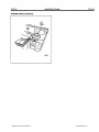
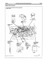
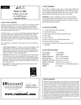
LUBRICATION The illustration shows typical chassis and engine
lubrication points. Vehicles with optional or special
equipment may have slightly different or additional
lubrication points.
Copyright © 1990, Ford Motor Co.
A table of recommended lubricants is included at the
end of this Section.
www.techcapri.com
10-03-2
10-03-2
Lubrication Points and Lubricant Specifications
LUBRICATION (Continued)
Turbocharged Engine Shown, Naturally Aspirated
Engine Typical
IIm~"uOOOo~~[
MoIoro8ft
FULL
HOT
FULL
COLD
BRAKE MASTER CYLINDER
OIL FILTER
COAT GASKET WITH
ENGINE OIL
REPLACE AT
RECOMMENDED
INTERVAL
ENGINE OIL DIPSTICK
WITH VEHICLE PARKED ON
LEVEL GROUND
MAINTAIN OIL
LEVEL IN
THIS RANGE
AUTOMATIC TRANSAXLE
DIPSTICK
CHECK WITH
TRANSAXLE IN "PARK"
poweR STEERING PUMP
DIPSTICK
FLUID SHOULD BE
IN THE FULL COLD OR
FULL HOT RANGE
DEPENDING
ON TEMPERATURE
PCVVALVE
REPLAGEAT
RECOMMENDED
INTERVAL
(NATURALLY ASPIRATED
VALVE SHOWN TURBO
CHARGED VALVE TYPICAL)
COOLANT RESERVOIR
COOLANT SHOULD BE
BETWEEN FULL AND
LOW RANGE ON
RESERVOIR
V3084-A
Copyright © 1990, Ford Motor Co.
www.techcapri.com
10-03-3
10-03-3
Lubrication Points and Lubricant Specifications
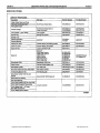
SPECIFICATIONS LUBRICANT SPECIFICATIONS
Description
Part Name
Ford Part Number
Ford Specification
Hinges, Hinge Checks and Pivots
Hood Latch and Auxiliary Catch
Parking Brake Cable
Multi·Purpose Grease Spray
07AZ·19584·AA
ESR-M1C159·A
Transaxle Linkage
Multi·Purpose Grease Spray or
Long-Li fe Lubricant
07AZ·19584·AA
C1AZ·19590·BA
ESR-M1 C159-A
ESA·M1C175-B
Lock Cylinders Door Latches
Lock Lubricant
D8AZ·19587·AA
ES13-M2C20-A
Steering Gear
Steering Gear Grease
C3AZ·19578·A
ESW-M1C87-A
Steering Pump
Transaxle (Automatic)
Transaxle (Manual)
MERCON®
XT·2-QDXor
XT·2·DOX
MERCON®
Outboard CV Joints
Constant Velocity Joint Bearing Grease
E2FZ·1959Q..B
ESP-M1C21S-A
Inboard CV Joints
Constant Velocity Joint Grease
E43Z·19590-A
ESp·M1C207·A
Engine Oil Filter
Long-Life Oil Filter FL-816
E9GZ·6731-B
-
Engine Oil
Motorcraft:
5W30 Super Premium
10W40 Super Premium
10W30 Premium
2OW40 Premium
SAE·30 Super Duty
15W40 Super Duty
XO-5W3Q..QSP
XO-10W4Q..QSP
X()..10W30·QP
XO-20W4Q..QP
XO-3Q..QSD
X()..15W4Q..QSD
ESE·M2C153-E and
API Category SG
Speedometer Cable
Speedometer Cable Lube
D2AZ·19581·A
ESF·M1 C16Q..A
Engine Cootant
Premium CoOling System Fluid
E2FZ·19549-AA
ESE-M97B44-A
Brake Master Cylinder
H.D. Brake Fluid
C6AZ·19542·AA or BA
ESA·M6C25-A
Disc Brake Caliper and Anchor Plate Slides
Disc Caliper Lubricant
D7AZ·19590-A
ESA·M1C172·A
TIre Mounting Bead (of Tire)
Tire Mounting Lube
D9AZ·19583-A
ESA·M1BS-A
Motorcraft SAE 1OW30 Engine Oil
XO-lOW3Q..QP
ESE-M2C153-C
Long-Life Lubricant
C1AZ-19590-BA
ESA-M1 C75-B
. Brake Master Cylinder Push Rod and
• Bushing
Brake Padal Pivot Bushing
Rear Wheel Bearings
Clutch Pedal Quadrant and Pawl Pivot Holes
Clutch Cable Connection Transaxle End
Clutch Release Lever At Fingers
(Both Sides and Fulcrum)
Clutch Release Bearing Retainer
CV30&5-A
Copyright © 1990, Ford Motor Co.
www.techcapri.com
10-04-1 10-04-1
Hoisting, Jacking and Towing
SECTION 10-04 Hoisting, Jacking and Towing SUBJECT PAGE
HOISTING AND JACKING
Hoisting ••••.•••••••.••••.••••.•.•.•.•.•..•••...•.............•.......... 10-04-2
Jacking ••••.•••••••.•••••••••.•...•..•..•••................•••...•..•... 10-04-1
TOWING
Front- T-Hook Procedure ..................................... 10-04-5
Rear-T·Hook Procedure ...................................... 10-04·6
PAGE
SUBJECT TOWING (Cont'd.)
Towing Precautions ...............................................10-04-3
Towing Procedures................................................10-o4·4
Towing Slings ........................................................ 10-04·3
VEHICLE APPLICATION ............................................. 10-04·1 VEHICLE APPLICATION
Capri.
HOISTING AND JACKING CAUTION: The service jack provided with the
vehicle is only intended to be used in an
emergency for changing a deflated tire. Never
use the service Jack to hoist the vehicle for any
other service. Refer to the Owner Guide when
using the jack supplied with the vehicle.
• The positions shown are the only acceptable
locations for jacking and supporting the vehicle.
• When jacking the rear of the vehicle make sure that
the jack head does not damage the rear stabilizer
bar (if equipped).
• When jacking the complete vehicle, always jack and
support the rear end first.
• When using body sill locations, use only jack stands
with cushion pads. They will prevent accidental
damage to the paint or body.
• Using only triangular based jackstands, position
them under the vehicle so that one of the three
stand legs always points toward the side of the
vehicle.
• Under no conditions should the jack or chassis
stand come in contact with the trailing link or any
other suspension component at any time.
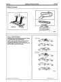
Jacking Before starting any repairs that involve jacking the
vehicle, it is important that all vehicle jacking
To begin with, be sure that only the correct jacking and
support locations are used at all times. The following
illustration shows the location points for positioning
jacking equipment, other than the service jack
supplied with the vehicle.
instructions are understood.
Copyright © 1990, Ford Motor Co.
www.techcapri.com
10-04-2
Hoisting, Jacking and Towing
10-04-2
HOISTING AND JACKING (Continued)
FRONT JACK POSITION:
AT THE FRONT OF THE ENGINE MOUNT CROSSMEMBER
JACKSTAND POSITIONS: ON BOTH SIDE SILLS (FRONT) REAR
JACK POSITION:
AT THE CENTER OF THE REAR CROSSMEMBER
JACKSTAND POSITIONS: ON BOTH SIDE SILLS (REAR) V4109-A
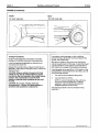
Hoisting
When hoisting a vehicle. always position lifting pads so
that they are in contact with the side sills. Never allow
the vehicle to be lifted by the trailing links.
Copyright © 1990, Ford Motor Co.
www.techcapri.com
10-04-3
10-04-3
Hoisting, Jacking and Towing
HOISTING AND JACKING (Continued)
FRONT
REAR
On both side sills
On both side sills
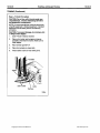
TOWING Towing Precautions
CAUTION: When either towing hooks or chains
are used, always pull the cable or chain straight
from the hook; do not apply any sideways force
to it. To prevent damage, do not take up slack too
quickly in the cable or chain. The rear towing
hook should be used only in an emergency
situation, (e.g., to pull the vehicle from a ditch, a
snowbank, or mud).
Do not tow the vehicle backward with drive wheels on
the ground. This may damage the transaxle's internal
parts.
Do not tow with J-hooks under any circumstances.
J-hooks will damage driveline and suspension
components.
WARNING: VEHICLES EQUIPPED WITH PLASTIC
BUMPER BARS CANNOT BE SAFELY LIFTED
USING CONVENTIONAL CHAINS OR SLINGS.
THESE VEHICLES SHOULD BE FLAT TOWED OR
TRANSPORTED USING DOLLIES, A FLAT-BED
TRAILER OR TILT-BED VEHICLES.
Towing Slings
Copyright © 1990, Ford Motor Co.
To avoid possible damage to bumper system, lower
body panels, or air dams, a special wide-belt sling
should be used to lift and tow this vehicle.
www.techcapri.com
10-04-4
HOisting, Jacking and Towing
10-04-4
TOWING (Continued)
FRONT
REAR
On both side silis
On both side sills
Y3180-A
Towing Procedures
Proper towing equipment is necessary to prevent
damage to the vehicle during any towing operation.
Laws and regulations applicable to vehicles in tow
must always be observed.
Release the parking brake and place the shift lever in
NEUTRAL. Insert and turn the ignition key to unlock the
steering column.
CAUTION: When a vehicle is towed on its front
wheels do not use the vehicle steering column
lock to lock the front wheels in the straight ahead
position. If it is necessary to lock the front
wheels, a steering wheel clamping device must
be used.
CAUTION: Do not use J-hooks under any
circumstances. J-hooks will cause damage to
drivetrain and suspension components.
Copyright © 1990, Ford Motor Co.
If excessive vehicle damage or other conditions
prevent towing a vehicle with its drive wheels off the
ground, use wheel dollies.
With all four wheels on the ground, the vehicle may
only be towed forward. In this case, it cannot be towed
in excess of 56 km I h (35 mph) for more than 80 km
(50 miles) without danger of damaging the transaxle.
If towing speed will exceed 56 km / h (35 mph) or if the
towing distance will exceed 80 km (50 miles), use one
of the following methods:
1.
Tow with the front wheels off the ground.
2.
Use a flat·bed tow vehicle.
NOTE: It is recommended that this vehicle be
towed with wheel lift equipment or flatbed
equipment. Use the following procedures if
slingbelt equipment must be used.
The following illustration shows standard towing
equipment.
www.techcapri.com
10-04-5
Hoisting, Jacking and Towing
10-04-5
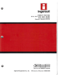
TOWING (Continued)
WOOD CROSSSEAM
TOWING SLING
MATERIAL - CROSSBEAM
1 ·4 x4 x 4 It. -2x4 LUMBER
ACTUALLY MEASURES 1 112" x 3 1/2"
1 -4 x4 x Sit. -4 x4 LUMBER
ACTUALLY MEASURES 3 112" x 3 112"
Y412t-A
Front-T-Hook Procedure
CAUTION: Do not tow from the front with T-hooks
or J-hooks under any circumstances.
NOTE: It is recommended that the vehicle be towed
with wheel lift equipment or flatbed equipment. If
slingbelt equipment must be used. tow the car from the
FRONT TOWING
rear with dollies under the front wheels.
REAR TOWING
~
CAUTION
Y2667-A
Copyright © 1990, Ford Motor Co.
www.techcapri.com
Hoisting, Jacking and Towing
10-04-6
10-04-6
TOWING (Continued)
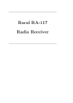
Rear-T-Hook Procedure
CAUTION: Do not tow with J-hooks under any
circumstances. J-hooks will damage driveline
and suspension components.
NOTE: It is recommended the vehicle be towed with
wheel lift equipment or flatbed equipment. If slingbelt
equipment must be used. perform the following
procedure.
CAUTION: To prevent damage, do not place 4x4
or slings under tailpipe.
1.
Insert T-hook in tiedown bracket.
2.
Place a 4x4 under rear bumper as close as
possible to the tiedown bracket. Make sure to
clear tailpipe.
3.
Place towbar against 4x4.
4.
Place front wheels on wheel dolly.
5.
Attach safety chains to rear trailing arms.
TON CHAIN
Y41ao.A
Copyright © 1990, Ford Motor Co.
www.techcapri.com