1
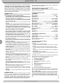
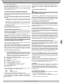
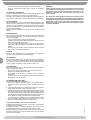
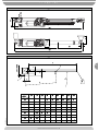
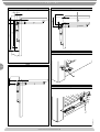
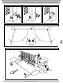
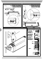
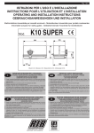
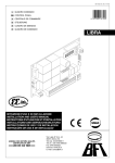
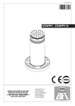
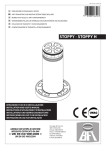
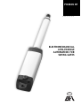
PHOBOS BT D811316 10-11-01 Vers. 02 ELECTROMECHANICAL LOW-VOLTAGE AUTOMATION FOR SWING GATES PHOBOS BT 156 1) GENERAL SAFETY WARNING! An incorrect installation or improper use of the product can cause damage to persons, animals or things. • The “Warnings” leaflet and “Instruction booklet” supplied with this product should be read carefully as they provide important information about safety, installation, use and maintenance. • Scrap packing materials (plastic, cardboard, polystyrene etc) according to the provisions set out by current standards. Keep nylon or polystyrene bags out of children’s reach. • Keep the instructions together with the technical brochure for future reference. • This product was exclusively designed and manufactured for the use specified in the present documentation. Any other use not specified in this documentation could damage the product and be dangerous. • The Company declines all responsibility for any consequences resulting from improper use of the product, or use which is different from that expected and specified in the present documentation. • Do not install the product in explosive atmosphere. • The construction components of this product must comply with the following European Directives: 89/336/CEE, 73/23/EEC, 98/37/EEC and subsequent amendments. As for all non-EEC countries, the abovementioned standards as well as the current national standards should be respected in order to achieve a good safety level. • The Company declines all responsibility for any consequences resulting from failure to observe Good Technical Practice when constructing closing structures (door, gates etc.), as well as from any deformation which might occur during use. • The installation must comply with the provisions set out by the following European Directives: 89/336/CEE, 73/23/EEC, 98/37/EEC and subsequent amendments. • Disconnect the electrical power supply before carrying out any work on the installation. Also disconnect any buffer batteries, if fitted. • Fit an omnipolar or magnetothermal switch on the mains power supply, having a contact opening distance equal to or greater than 3mm. • Check that a differential switch with a 0.03A threshold is fitted just before the power supply mains. • Check that earthing is carried out correctly: connect all metal parts for closure (doors, gates etc.) and all system components provided with an earth terminal. • Fit all the safety devices (photocells, electric edges etc.) which are needed to protect the area from any danger caused by squashing, conveying and shearing. • Position at least one luminous signal indication device (blinker) where it can be easily seen, and fix a Warning sign to the structure. • The Company declines all responsibility with respect to the automation safety and correct operation when other manufacturers’ components are used. • Only use original parts for any maintenance or repair operation. • Do not modify the automation components, unless explicitly authorised by the company. • Instruct the product user about the control systems provided and the manual opening operation in case of emergency. • Do not allow persons or children to remain in the automation operation area. • Keep radio control or other control devices out of children’s reach, in order to avoid unintentional automation activation. • The user must avoid any attempt to carry out work or repair on the automation system, and always request the assistance of qualified personnel. • Anything which is not expressly provided for in the present instructions, is not allow 2) GENERAL OUTLINE Electromechanical piston designed to automatically operate residential gates. The irreversible gearmotor keeps the gate locked both in the closing and opening positions, making the use of the electric lock redundant. The actuator is supplied with an electronic torque limiter. The unit is controlled by means of an electronic control board with torque adjustment. End-of-stroke operation is controlled by two magnetic limiting devices. The actuator features an obstacle detection system in compliance with EN12453 and EN 12445 Standards. The following optional accessories are available on request: - Buffer battery kit mod. PHOBOS-BT BAT Allows operation of the automation even when there is no mains power supply for a short period of time. 3) TECHNICAL SPECIFICATIONS 3.1) PHOBOS BT Power supply : ................................................................ 24V single-phase Motor revolutions : .................................................................... 3800 min -1 Absorbed power : ...............................................................................40 W Absorbed current : ............................................................................. 1.5 A Motion transmission : ........................................................... push and pull Push and pull force : ....................................................... 2000 N (~200 kg) Working stroke : ............................................................................. 280 mm Stem speed : ................................................................... 14 mm/s approx. Impact reaction : ...................... Torque limiter aboard Libra control board End-of-stroke limitino devices: .............. Magnetic, built-in and adjustable Manual manoeuvre : ........................................................ CLS release key No. of manoeuvres in 24hours: ......................................... 60 manoeuvres Max. leaf length : ......................................................................... 1800 mm Max. leaf weight : ........................................................... 2500 N (~250 kg) Environmental conditions: ....................................... from -20 °C to +80 °C Protection level : ................................................................................ IP 44 Dimensions : ................................................................................. See fig.1 Controller weight : .................................................................... 50N (~5kg) Lubrication : .................................................................. permanent grease 3.2) BATTERY KIT PHOBOS-BT BAT Charging voltage: .......................................................................... 27.2Vdc Charging current: ............................................................................ 130mA Outside temperature when values were measured: .......................... 25°C Battery capacity: ................................................................. 2x (12V 1.2Ah) Flat battery protection threshold: .................................................. 20.4Vdc Battery charging time: ................................................................. 12/14 hrs 4) INSTALLATION OF THE ACTUATOR 4.1) Preliminary checks Check that: • The gate structure is sufficiently sturdy. • Also make sure that the actuator pushes against the leaf reinforced section. • The leaves move manually and without effort all along their stroke. • The door stop plates are fitted at the end of both closing and opening strokes. • If the gate has not been recently installed, check the wear condition of all components. • Repair or replace faulty or worn parts. The automation reliability and safety are directly influenced by the state of the gate structure. The diagram in fig. 2 should be used as a reference for installation and consult the table for the distances in mounting the gate post. The diagram in fig. 2 uses the following legend: P Gate post rear fastening bracket F Front leaf fastening fork a-b “P” bracket installation value C Distance between fixing points (C = 993 mm) D Gate length X Distance from gate axis to the edge of the post Z Always over 45 mm (b - X) kg max. weight of leaf α° leaf opening in degrees 4.2) How to read the installation distance tables Select “a” and “b” according to the angle in degrees α° that the gate has to open. The table shows the ideal value for “a” and “b” for an opening of α° = 90° at constant speed. If there is too large a difference between “a” and “b”, the leaf will not travel smoothly and the pushing or pulling force will fluctuate during its stroke. To respect the opening speed and ensure the controller operates correctly, it is best to keep the difference between “a” and “b” as low as possible. When “a” and “b” are at their maximum, the piston develops the maximum force. AUTOMATION FOR SWING GATES D811316_02 Thank you for buying this product, our company is sure that you will be more than satisfied with the product’s performance. The product is supplied with a “Warnings” leaflet and an “Instruction booklet”. These should both be read carefully as they provide important information about safety, installation, operation and maintenance. This product complies with the recognised technical standards and safety regulations. We declare that this product is in conformity with the following European Directives: 89/336/EEC and 73/ 23/EEC (and subsequent amendments). PHOBOS BT 4.3) Off-standard installations. Fig. 3 shows an installation with a recess when there is not sufficient space between the leaf and perimeter wall. When the leaf’s position does not allow for an “a” value listed in the table, the leaf’s hinge pivot can be shifted (fig. 4), or a recess can be made cut out of the actual gate-post (fig. 5). 4.4) Mounting the brackets to the gate-post and to the gate. Fix the bracket “P” (fig. 6) to the gate-post with a good welding. The fork “F” should be welded in the same way to the gate taking care that the actuator can then be mounted perfectly horizontal to the line of travel of the gate fig. 7. If the gate operates on a slope (opening inwards with an uphill driveway), fig. 7 gives the maximum oscillations of the piston with respect to its horizontal. • If the gate-post is in brick, the plate “PF” must be set soundly into the post using adequately sized cramps “Z” welded to the back of the plate (fig. 8). • If the gate-port is in stone and the gate is small, the plate “PF” can be mounted with four metal expansion plugs “T” (fig. 9). If a larger gate is being installed it would be better to use a corner plate “PF” (fig. 10). 5) GROUND GATE STOPS For the controller to operate correctly the gate stop “B” must be used both in opening and closing, as shown in fig. 11. 6) THE ELECTRICAL PLANT SET-UP (fig. 12). Lay out the electrical installation (fig. 16) with reference to the CEI 64-8 and IEC 364 provisions, complying with the HD 384 and other national standards in force for electrical installation. The mains power supply connections must be kept totally separate from the service connections (photocells, electric edges, control devices etc.). WARNING! For connection to the mains, use a multipolar cable with a minimum of 3x1.5mm2 cross section and complying with the previously mentioned regulations. For example, if the cable is out side (in the open), it has to be at least equal to H07RN-F, but if it is on the inside (or outside but placed in a plastic cable cannel) it has to be or at least egual to H05VV-F with section 3x1.5mm2. Connect the control and safety devices in compliance with the previously mentioned electrical installation standards. Fig.12 shows the number of connections and the cross section for power supply cables having a length of approximately 100 metres; in case of longer cables, calculate the cross section for the true automation load. When the auxiliary connections exceed 50-metre lengths or go through critical disturbance areas, it is recommended to decouple the control and safety devices by means of suitable relays. D811316_02 The main automation components are (fig.12): I Type-approved omnipolar circuit breaker with at least 3mm contact opening, provided with protection against overloads and short circuits, suitable for cutting out automation from the mains. If not already installed, place a type-approved differential switch with a 0.03A threshold in the circuit just before the automation system. Qr Control panel and incorporated receiver. SPL Heater board for operation at temperatures below 10°C (optional) S Key selector AL Blinker tuned in with antenna M Controller Fte Pair of outside photocells (transmitters) Fre Pair of outside photocells (receivers) Fti Pair of inside photocells with column (transmitters) Fri Pair of inside photocells with column (receivers) T 1-2-4 channel transmitter RG58 Antenna cable For the connection from the controller to the control board, three cables have been provided having the following functions: • red motor + • black motor • white end-of-stroke control Fig. 16 shows the wiring diagram of the LIBRA control unit. Should the opening or closing direction be incorrect, it is possible to invert the connections of motor + and motor - (red/black) on the control board. The first command after an interruption of the power supply should be an opening manoeuvre. The cable sections and numbering are indicated in the diagram (fig. 12). For distances of over 100 meters, the cable section must be increased. All metal masses in the housings of equipment and automation must be earthed. 7) ADJUSTING THE PUSHING FORCE WARNING: Check that the impact force value measured at the points established by the EN 12445 standard is lower than that specified in the EN 12453 standard. The pushing force is calibrated by means of the torque regulator in the control unit. The optimum torque must allow a complete opening or closing cycle with the minimum force necessary. An excessive torque can reduce the anti-crush safety. In the other case, an insufficient torque can impede the manoeuvres. Consult the control unit’s instruction manual. 8) ADJUSTMENT OF THE LIMITING DEVICES The correct adjustment of the limiting devices is obtained by positioning the end-of-stroke magnets correctly (FC1 and FC2 in Fig.1) with respect to the axis of the front bracket. Loosen the fastening screws of the magnets as described in the following paragraphs so that they can slide inside the endof-stroke track “B” (Fig.1). 8.1) Adjustment of the closing limiting devices (Fig.13): Move the leaf to the desired closing point, loosen the two screws A and B of the closing limiting device (FC1 in Fig.1) and move it so that the distance between the screw B and the axis of the front racket is 376 mm approximately (as shown in fig. 13). Perform a closing manoeuvre to make sure that the end-of-stroke limiting device operates correctly; if the leaf stops too far before the desired closing point, slightly move the limiting device towards the end of the stem; if, on the contrary, the leaf hits the ground closing stopping device and the actuator reverses its moving direction, move the end-of-stroke limiting device slightly towards the actuator body. After identifying the correct position of the limiting device , fix it using the two screws A and B. 8.2) Adjustment of the opening limiting devices (Fig.14): Move the leaf to the desired opening position, loosen the two screws C and D of the opening limiting device (FC2 in Fig.1) and move it so that the distance between the screw D and the axis of the front bracket is 376 mm approximately (as shown in fig. 13). Perform an opening manoeuvre to make sure that the end-of-stroke limiting device operates correctly; if the leaf stops too far before the desired opening point, slightly move the limiting device towards the actuator body; if, on the contrary, the leaf hits the ground closing stopping device and the actuator reverses its moving direction, move the end-of-stroke limiting device slightly towards the end of the stem. After identifying the correct position of the limiting device , fix it using the two screws C and D. N.B. When using the LIBRA control board, remember to slightly anticipate the intervention of the limiting devices because the stem, after intercepting the limiting devices, continues to move for a further 1-2 cm. (100 ms). In this way a perfect strike of the leaves against the ground supports is guaranteed. 9) MANUAL OPENING All controllers feature a key release mechanism. After lifting the lock cover (fig.15), insert the release key supplied and turn it clockwise by 90°. Push the leaf manually to open the gate. To reset the motorised operation, turn the key in the opposite direction and refit the cover. 10) COVERS An optional stem cover (mod.CPH) is available on request in order to protect the stem and to improve the appearance of the actuator. The actuator equipped with the stem cover mod. CPH looks like in fig.17. The stem cover is mounted on the right or left actuator by simply inverting the position of the cover and making sure that the water drain outlet is directed downwards. 11) CHECKING THE AUTOMATION Before considering the automation completely operational, the following checks must be made with great care: • Check that all the components are firmly anchored. • Control all the safeties work properly (i.e. photocells, pneumatic skirt, etc.). • Check the emergency manoeuvre control. AUTOMATION FOR SWING GATES 157 PHOBOS BT • Check the opening and closing manoeuvres using the controls. • Check the control unit’s electronic logic in normal (or customised) operation. 12) USE OF THE AUTOMATION Since the automation may be remote controlled either by radio or a Start button, it is essential that all safeties are checked frequently. Any malfunction should be corrected immediately by a qualified specialist. Keep children at a safe distance from the field of action of the automation. 13) THE CONTROLS With the automation the gate has a power driven opening and closing. The controls can come in various forms (i.e. manual, remote controlled, limited access by magnetic badge, etc.) depending on needs and installation characteristics. For details on the various command systems, consult the specific instruction booklets. Anyone using the automation must be instructed in its operation and controls. WARNINGS Correct controller operation is only ensured when the data contained in the present manual are observed. The company is not to be held responsible for any damage resulting from failure to observe the installation standards and the instructions contained in the present manual. The descriptions and illustrations contained in the present manual are not binding. The Company reserves the right to make any alterations deemed appropriate for the technical, manufacturing and commercial improvement of the product, while leaving the essential product features unchanged, at any time and without undertaking to update the present publication. 14) MAINTENANCE When carrying out maintenance operation on the controller, disconnect it from the mains power supply. The actuator does not require periodical maintenance operations. • Check the safety devices of the gate and automation. • Periodically check the pushing force and correct the value of the electric torque in the control board if necessary. • In case of unsolved operation failures, disconnect the unit from the mains power supply and ask for the intervention of qualified personnel (installer). When the unit is out of order, activate the manual release to perform manual opening and closing manoeuvres. 15) NOISE The aerial noise produced by the gearmotor under normal operating conditions is constant and does not exceed 70dB(A). 17) DISMANTLING When the automation system is disassembled to be reassembled on another site, proceed as follows: • Disconnect the power supply and the entire electrical installation. • Remove the gearmotor from its fixing base. • Disassemble the control panel, if separate, and all installation components. • In the case where some of the components cannot be removed or are damaged, they must be replaced. 18) TROUBLES AND SOLUTIONS 18.1) Incorrect operation of gearmotor a) Check for the presence of power supply to the gearmotor using a suitable instrument after opening or closing commands have been given. b) If the moving direction of the leaf is opposite to the right one, invert the motor running connections (motor +red/ motor - black). c) Should the gate stop and hit the ground stopping device and the actuator reverse its moving direction, it means that the limiting devices have not been adjusted correctly. If this happens on the opening stopping device, move the opening limiting device towards the hinge of the gate until the correct position is found(see adjustment of the limiting devices). If, on the contrary, this happens on the closing stopping device, move the closing limiting device towards the stem plug until the correct position is found (see adjustment of the limiting devices). 18.2) Incorrect operation of the electrical accessories All control and safety devices can cause, in case of failure, malfunctioning or stoppage of the automation. To identify the failure, it is advised to disconnect all the devices of the automation one by one until the one causing the problem is found. After fixing or replacing the defective device, reset all the devices previously disconnected. Refer to the relevant instruction manual for all the devices installed on the automation. AUTOMATION FOR SWING GATES D811316_02 158 16) SCRAPPING Materials must be disposed of in conformity with the current regulations. In case of scrapping, the automation devices do not entail any particular risks or danger. In case of recovered materials, these should be sorted out by type (electrical components, copper, aluminium, plastic etc.). PHOBOS BT 102 Fig. 1 FC2 B FC1 80 80 1027 713 10 280 1027 Fig. 2 159 F b x Z=b-x >45mm D α¡ a P kg C (mm) (mm) 100 110 120 130 a b 100 112 D811316_02 140 150 160 170 180 110 104 95 88 102 94 89 120 130 117 107 119 112 105 99 94 90 100 94 89 140 150 160 170 180 109 105 99 94 103 98 94 90 98 94 91 94 91 91 90 α¡ AUTOMATION FOR SWING GATES PHOBOS BT Fig. 3 Fig. 4 45 1050 800 b b b a Fig. 6 Fig. 5 160 b P Fig. 7 + 4° - 4° D811316_02 F AUTOMATION FOR SWING GATES PHOBOS BT Fig. 8 Fig. 9 Fig. 10 T Z PF PF Fig. 11 FA FA FA Sx Dx 161 Fig. 12 M AL S Fre 2 mm 1.5 4x 2 m 1m 2x Fti 2 M P 3x1mm 2 3x1 m 1m 4x mm 2 RG R 58 CF Q 2x1 Fte .5m m2 2x1 mm 2 2 mm 1.5 4x D811316_02 T 2 Fri m 1m 4x CF AUTOMATION FOR SWING GATES I 3x1 2x1 .5m m2 .5m m2 PHOBOS BT Fig. 13 Fig. 14 Regolazione fine corsa chiusura Adjustment of the closing limiting devices Rglage de la bute de fin de course de fermeture Einstellung des Schlie§ungs-Endschalters Regulacin del fin de carrera de cierre Regulao do final de curso de fecho Regolazione fine corsa apertura Adjustment of the opening limiting devices Rglage de la bute de fin de course dÕouverture Einstellung des ffnungs-Endschalters Regulacin del fin de carrera de apertura Regulao do final de curso de abertura 376 mm 376 mm 376 mm FC1 D B FC2 376 mm Fig. 15 Fig. 16 JP9 M2 3 + Rosso/Red/Rouges Rot/Rojos/Vermelos 162 L 230V ~ 1 N 2 + 4 - Nero/Black/Noir Schwartz/Negro/Preto M2 5 FC Bianco/White/Blanc Wei§e/Blanco/Branco M1 6 + Rosso/Red/Rouges Rot/Rojos/Vermelos FC + M1 FC 7 - Nero/Black/Noir Schwartz/Negro/Preto 3 4 5 6 7 JP9 8 9 8 FC Bianco/White/Blanc Wei§e/Blanco/Branco 40W max. 12 13 24V ~ VSafe 14 NO NC NC LIBRA 10 11 24V ~ NO NO COM 15 START 16 STOP 17 PHOT 18 FAULT 19 PED 20 JP8 21 SCA / II¡CH.R ANT. AUTOMATION FOR SWING GATES JP1 22 ANT SHIELD 23 JP7 24 D811316_02 A C PHOBOS BT Fig. 17 CPH D811316_02 163 AUTOMATION FOR SWING GATES