1
Brother Laser Printer
HL-1260e/HL-1660
USER’S GUIDE
I
Trademarks
Brother is a registered trademark of Brother Industries, Ltd.
Apple and LaserWriter are registered trademarks, and TrueType is a trademark of
Apple Computer, Inc.
Centronics is a trademark of Genicom Corporation.
EPSON is a registered trademark, and FX-850 and FX-80 are trademarks of Seiko
Epson Corporation.
Hewlett-Packard, HP and PCL are registered trademarks, and HP LaserJet 4+, HP
LaserJet Plus, HP LaserJet II, HP LaserJet IID, HP LaserJet IIID, HP-GL, HPGL/2, and Bi-Tronics are trademarks of Hewlett-Packard Company.
IBM, Proprinter XL, Proprinter, and IBM/PC are registered trademarks of
International Business Machines Corporation.
Intellifont is a registered trademark of AGFA Corporation, a division of Miles, Inc.
Microsoft and MS-DOS are registered trademarks of Microsoft Corporation.
Windows is a registered trademark of Microsoft Corporation in the United States
and other countries.
PostScript is a registered trademark of Adobe Systems Incorporated.
All other brand and product names mentioned in this user’s guide are registered
trademarks or trademarks of respective companies.
Compilation and Publication
Under the supervision of Brother Industries Ltd., this manual has been compiled
and published, covering the latest product descriptions and specifications.
The contents of this manual and the specifications of this product are subject to
change without notice.
Brother reserves the right to make changes without notice in the specifications and
materials contained herein and shall not be responsible for any damages (including
consequential) caused by reliance on the materials presented, including but not
limited to typographical and other errors relating to the publication.
©1996 Brother Industries Ltd.
Shipment of the Printer
If for any reason you must ship your Printer, carefully package the Printer to avoid any
damage during transit. It is recommended that you save and use the original packaging. The
Printer should also be adequately insured with the carrier.
WARNING
When shipping the Printer, the TONER CARTRIDGE must be removed from the Printer.
Failure to remove the Toner Cartridge during shipping will cause severe damage to the
Printer and will VOID THE WARRANTY.
II
Laser Printer
HL-1260e/HL-1660
USER’S GUIDE
(For USA & CANADA Only)
For technical and operational assistance, please call:
In USA
In CANADA
1-800-276-7746
714-859-9700 Ext. 329
1-800-853-6660
514-685-6464
(outside California)
(within California)
(within Montreal)
If you have comments or suggestions, please write us at:
In USA
In CANADA
Printer Customer Support
Brother International Corporation
15 Musick
Irvine, CA 92718
Brother International Corporation (Canada), Ltd.
- Marketing Dept.
1, rue Hôtel de Ville
Dollard-des-Ormeaux, PQ, Canada H9B 3H6
BBS
For downloading drivers from our Bulletin Board Service, call:
In USA
1-714-859-2610
In CANADA
1-514-685-2040
Please log on to our BBS with your first name, last name and a four digit number for your
password. Our BBS supports modem speeds up to 14,400, 8 bits no parity, 1 stop bit.
Fax-Back System (For USA only)
Brother Customer Service has installed an easy to use Fax-Back System so you can get instant
answers to common technical questions and product information for all Brother products. This is
available 24 hours a day, 7 days a week. You can use the system to send the information to any
fax machine, not just the one you are calling from.
Please call 1-800-521-2846 and follow the voice prompts to receive faxed instructions on how to
use the system and your index of Fax-Back subjects.
DEALERS/SERVICE CENTERS (USA only)
For the name of an authorized dealer or service center, call 1-800-284-4357.
SERVICE CENTERS (Canada only)
For service center addresses in Canada, call 1-800-853-6660
INTERNET ADDRESS
For technical questions and downloading drivers: http://www.brother.com
i
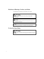
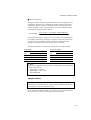
Definitions of Warnings, Cautions, and Notes
The following conventions are used in this User’s Guide:
Warning
Indicates warnings that must be observed to prevent possible
personal injury.
Caution
Indicates cautions that must be observed to use the printer properly or
prevent damage to the printer.
✒ Note
Indicates notes and useful tips to remember when using the printer.
To Use the Printer Safely
Warning
The fixing roller is extremely hot during operation. Remove the paper
carefully.
ii
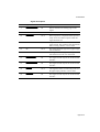
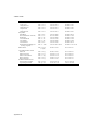
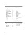
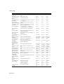
TABLE OF CONTENTS
TABLE OF CONTENTS
IMPORTANT INFORMATION: REGULATIONS ......................... ix
CHAPTER 1 GENERAL.............................................................. 1-1
ABOUT THIS MANUAL...................................................................... 1-1
ABOUT CHAPTERS ON THE FLOPPY DISK ................................... 1-3
ABOUT THIS PRINTER....................................................................... 1-4
Features ............................................................................................ 1-4
Options ............................................................................................. 1-10
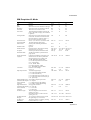
CHAPTER 2 GETTING STARTED.............................................. 2-1
BEFORE USING THE PRINTER ......................................................... 2-1
Checking the Components................................................................ 2-1
Printer Carton.............................................................................. 2-1
Toner Cartridge ........................................................................... 2-2
General View .................................................................................... 2-3
Operating and Storage Environment ............................................... 2-4
Power Supply.............................................................................. 2-4
Environment ............................................................................... 2-4
SETTING UP THE PRINTER............................................................... 2-5
Opening and Closing the Printer ...................................................... 2-5
Removing the Protective Parts.......................................................... 2-6
Installing the Toner Cartridge........................................................... 2-7
Loading Paper in the Paper Cassette ................................................ 2-11
Connecting the Printer to Your Computer ........................................ 2-17
Turning the Printer On and Off ........................................................ 2-19
Plugging in the Power Cord ....................................................... 2-19
Pressing the POWER Switch ...................................................... 2-20
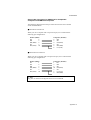
Printing the Test Patterns or Lists..................................................... 2-21
Checking the Printed Test Pattern or Demo Page............................. 2-24
iii
USER’S GUIDE
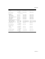
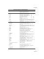
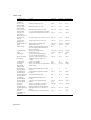
CHAPTER 3 BEFORE WORKING WITH THE PRINTER ........... 3-1
SOFTWARE COMPATIBILITY............................................................ 3-1
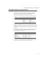
AUTOMATIC EMULATION SELECTION.......................................... 3-3
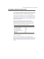
AUTOMATIC INTERFACE SELECTION ........................................... 3-5
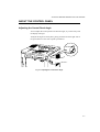
ABOUT THE CONTROL PANEL ........................................................ 3-7
Adjusting the Control Panel Angle................................................... 3-7
Selecting the Local Language Display ............................................. 3-8
Using the Panel Switches ................................................................. 3-9
Printer Settings ................................................................................. 3-10
User Settings............................................................................... 3-10
Factory Settings .......................................................................... 3-10
PAPER HANDLING.............................................................................. 3-11
Print Media ....................................................................................... 3-11
Paper Size ................................................................................... 3-11
Using Envelopes ......................................................................... 3-13
Cassette Feed.................................................................................... 3-15
Manual Feed ..................................................................................... 3-16
Face Down Print Delivery ................................................................ 3-17
Face Up Print Delivery ..................................................................... 3-17
CHAPTER 4 CONTROL PANEL................................................. 4-1
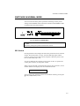
DISPLAY AND LAMPS........................................................................ 4-1
Display ............................................................................................. 4-1
Printer Status Messages .............................................................. 4-2
Lamps ............................................................................................... 4-4
READY....................................................................................... 4-4
DATA .......................................................................................... 4-4
ALARM...................................................................................... 4-4
ON LINE .................................................................................... 4-4
iv
TABLE OF CONTENTS
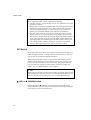
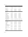
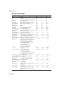
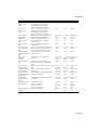
SWITCHES IN NORMAL MODE........................................................ 4-5
SEL Switch ...................................................................................... 4-5
SET Switch...................................................................................... 4-6
▲ (UP) or ▼ (DOWN) Switch ........................................................ 4-6
MODE Switch ................................................................................. 4-7
MODE Switch Settings in HP LaserJet 4+,
EPSON FX-850, and IBM Proprinter XL Modes....................... 4-8
MODE Switch Settings in BR-Script Mode ............................... 4-11
MODE Switch Settings in HP-GL Mode.................................... 4-13
Basic Operation Procedures........................................................ 4-15
Operation Example: Selecting the Parallel Interface ................. 4-16
INTERFACE MODE .................................................................. 4-17
FORMAT MODE ....................................................................... 4-20
ORIENTATION ..................................................................... 4-20
AUTO MODE........................................................................ 4-21
PAGE FORMAT MODE........................................................ 4-22
GRAPHICS MODE ............................................................... 4-25
RESOLUTION MODE............................................................... 4-28
PAGE PROTECTION ................................................................. 4-31
CARD OPERATION .................................................................. 4-32
ADVANCED MODE .................................................................. 4-41
NETWORK MODE............................................................... 4-41
ERROR PRINT...................................................................... 4-44
CONTINUE MODE .............................................................. 4-44
BUZZER SETTING .............................................................. 4-45
SCALABLE FONT ............................................................... 4-45
PRINT DENSITY.................................................................. 4-46
INPUT BUFFER.................................................................... 4-46
SAVE SETTINGS.................................................................. 4-47
PAGE COUNTER....................................................................... 4-48
EXIT MODE .............................................................................. 4-48
FONT Switch................................................................................... 4-49
Setting the Font and Symbol Set in the HP LaserJet 4+ Mode ... 4-49
Setting the Font and Character Set in the EPSON FX-850,
or IBM Proprinter XL Mode ...................................................... 4-54
List of Fonts................................................................................ 4-59
List of Symbol/Character Sets .................................................... 4-60
FORM FEED Switch (REPRINT Switch) ...................................... 4-61
Form Feed................................................................................... 4-61
Reprint Function ......................................................................... 4-61
CONTINUE Switch ....................................................................... 4-63
v
USER’S GUIDE
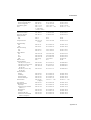
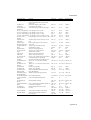
SWITCHES IN SHIFT MODE.............................................................. 4-64
SHIFT Switch ................................................................................. 4-64
EMULATION Switch ..................................................................... 4-65
About Emulation Modes............................................................. 4-67
ECONOMY Switch......................................................................... 4-69
TONER SAVE MODE................................................................ 4-69
POWER SAVE MODE ............................................................... 4-69
FEEDER Switch.............................................................................. 4-70
FEEDER ..................................................................................... 4-70
MP FIRST................................................................................... 4-72
MANUAL FEED ........................................................................ 4-73
MP TRAY SETTING.................................................................. 4-73
MEDIA TYPE ............................................................................ 4-74
DUPLEX MODE........................................................................ 4-75
COPY Switch................................................................................... 4-77
RESET Switch................................................................................. 4-78
List of Factory Settings............................................................... 4-79
TEST Switch.................................................................................... 4-85
HEX DUMP MODE .............................................................................. 4-88
CHAPTER 5 OPTIONS ............................................................... 5-1
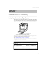
LOWER TRAY UNIT (LT-1200/LT-1600) ............................................ 5-1
Loading Paper from the Lower Paper Cassette ................................ 5-1
FONT CARTRIDGE/CARD, FLASH MEMORY/HDD CARD ........... 5-2
Installing a Font Cartridge/Card, Flash Memory Card and
HDD Card ........................................................................................ 5-2
Selecting the Optional Fonts ............................................................ 5-4
MODULAR I/O CARD ......................................................................... 5-6
RAM EXPANSION ............................................................................... 5-7
DUPLEX UNIT (DX-1200/DX-1600) .................................................. 5-11
vi
TABLE OF CONTENTS
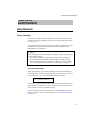
CHAPTER 6 MAINTENANCE..................................................... 6-1
MAINTENANCE................................................................................... 6-1
Toner Cartridge................................................................................. 6-1
Toner Empty Message ................................................................ 6-1
Replacing the Toner Cartridge .................................................... 6-2
Cleaning ........................................................................................... 6-5
Cleaning the Printer Exterior ...................................................... 6-5
Cleaning the Printer Interior ....................................................... 6-6
CHAPTER 7 TROUBLESHOOTING ............................................... 7-1
TROUBLESHOOTING ......................................................................... 7-1
Operator Call Messages.................................................................... 7-1
Error Messages ................................................................................. 7-3
Service Call Messages ...................................................................... 7-5
Possible Troubles.............................................................................. 7-6
Paper Jam.................................................................................... 7-6
Unsatisfactory Printouts.............................................................. 7-12
APPENDICES ............................................................................Appendix-1
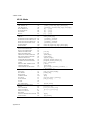
PRINTER SPECIFICATIONS............................................................... Appendix-1
Printing ............................................................................................. Appendix-1
Functions .......................................................................................... Appendix-2
Electrical and Mechanical ................................................................ Appendix-3
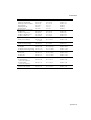
PAPER SPECIFICATIONS.................................................................... Appendix-4
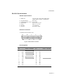
INTERFACE SPECIFICATIONS .......................................................... Appendix-8
Bi-directional Parallel Interface........................................................ Appendix-8
Pin Assignment ........................................................................... Appendix-8
Signal Description ...................................................................... Appendix-9
Parallel Cable Connection for IBM-PC/AT or
Compatible Computers and IBM-PS/2 Computers................... Appendix-10
vii
USER’S GUIDE
RS-232C Serial Interface................................................................ Appendix-11
Standard Specifications............................................................. Appendix-11
Interface Connectors .................................................................Appendix-11
Pin Assignment ......................................................................... Appendix-11
Signal Description ....................................................................Appendix-12
Serial Cable Connection for IBM-PC/AT or
Compatible Computers and IBM-PS/2 Computers................... Appendix-13
SYMBOL/CHARACTER SETS.......................................................... Appendix-14
OCR Symbol Sets........................................................................... Appendix-14
HP LaserJet 4+ Mode .....................................................................Appendix-15
EPSON Mode ................................................................................. Appendix-22
IBM Mode ...................................................................................... Appendix-25
HP-GL Mode.................................................................................. Appendix-27
Symbol Sets Supported by the Printer’s Intellifont Compatible
Typefaces........................................................................................ Appendix-32
Symbol Sets Supported by the Printer’s TrueType and Type 1
Font Compatible, and Original Typefaces ...................................... Appendix-34
QUICK REFERENCE OF COMMANDS ........................................... Appendix-36
HP LaserJet 4+ Mode ..................................................................... Appendix-36
PCL Command Sets..................................................................Appendix-36
CCITT G3/G4 and TIFF ........................................................... Appendix-49
Horizontal 1200-dpi Image Format Mode ................................ Appendix-52
HP-GL/2 Command Sets .......................................................... Appendix-55
Printer Job Language Commands Syntax .................................Appendix-57
EPSON FX-850 Mode....................................................................Appendix-58
IBM Proprinter XL Mode............................................................... Appendix-61
HP-GL Mode.................................................................................. Appendix-64
Bar Code Control............................................................................ Appendix-66
Print Bar Codes or Expanded Characters..................................Appendix-66
INDEX........................................................................................... Index-1
viii
REGULATIONS
IMPORTANT INFORMATION: REGULATIONS
Federal Communications Commission Compliance Notice
(For U.S.A. only)
This equipment has been tested and found to comply with the limits for a
Class B digital device, pursuant to Part 15 of the FCC Rules. These limits
are designed to provide reasonable protection against harmful
interference in a residential installation. This equipment generates, uses,
and can radiate radio frequency energy and, if not installed and used in
accordance with the instructions, may cause harmful interference to radio
communications. However, there is no guarantee that interference will
not occur in a particular installation. If this equipment does cause harmful
interference to radio or television reception, which can be determined by
turning the equipment off and on, the user is encouraged to try to correct
the interference by one or more of the following measures:
– Reorient or relocate the receiving antenna.
– Increase the separation between the equipment and receiver.
– Connect the equipment into an outlet on a circuit different from that
to which the receiver is connected.
– Consult the dealer or an experienced radio/TV technician for help.
Important – About the Interface Cable
This printer has been certified to comply with FCC standards, which are
applied to the U.S.A. only. A shielded interface cable should be used
according to FCC 15.27(C). In addition, a grounded plug should be
plugged into a grounded AC outlet after checking the rating of the local
power supply for the printer to operate properly and safely.
☛ Caution
Changes or modifications not expressly approved by Brother Industries,
Ltd. could void the user’s authority to operate the equipment.
International Energy Star Compliance Statement (For HL-1660
only)
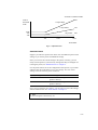
The purpose of the International Energy Star Program is to promote the
development and popularization of energy-efficient office equipments, which
includes computers, monitors, printers, facsimile receivers and copy machines
world-wide.
As an International Energy Star partner, Brother Industries, Ltd. has decided that
this product meets the guideline of the program.
ix
USER’S GUIDE
Canadian Department of Communications Compliance
Statement (For Canada only)
This digital apparatus does not exceed the Class B limits for radio noise
emissions from digital apparatus as set out in the interference- causing
equipment standard entitled “Digital Apparatus”, ICES-003 of the
Department of Communications.
Avis de conformité aux normes du ministère des
Communications du Canada (Pour Canada Seul)
Cet appareil numérique respecte les limites de bruits radioélectriques
applicables aux appareils numériques de Classe B prescrites dans la
norme sur le matériel brouilleur : “Appareils Numériques”, NMB-003
édictée par le ministère des Communications.
Laser Safety (110-120 V model only)
This printer is certified as a Class I laser product under the U.S.
Department of Health and Human Services (DHHS) Radiation
Performance Standard according to the Radiation Control for Health and
Safety Act of 1968. This means that the printer does not produce
hazardous laser radiation.
Since radiation emitted inside the printer is completely confined within
protective housings and external covers, the laser beam cannot escape
from the machine during any phase of user operation.
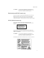
CDRH Regulations (110-120 V model only)
The Center for Devices and Radiological Health (CDRH) of the U.S.
Food and Drug Administration (FDA) implemented regulations for laser
products on August 2, 1976. These regulations apply to laser products
manufactured from August 1, 1976. Compliance is mandatory for
products marketed in the United States. The label shown on the back of
the printer indicates compliance with the CDRH regulations and must be
attached to laser products marketed in the United States.
MANUFACTURED:
BROTHER INDUSTRIES, LTD.
15-1 Naeshiro-cho Mizuho-ku Nagoya, 467 Japan
This product complies with FDA radiation performance standards, 21
CFR chapter 1 subchapter J.
x
REGULATIONS
☛ Caution:
Use of controls, adjustments or performance of
procedures other than those specified in this manual
may result in hazardous radiation exposure.
Radio Interference(220-240 V model only)
This printer complies with EN55022(CISPR Publication 22)/Class B.
Before this product is used, ensure that you use a double-shielded
interface cable with twisted-pair conductors and that it is marked
“IEEE1284 compliant”. The cable must not exceed 1.8 metres in length.
IEC 825 (220-240 V model only)
This printer is a Class 1 laser product as defined in IEC 825
specifications. The label shown below is attached in countries where
required.
This printer has a Class 3B Laser Diode which emits invisible laser
radiation in the Scanner Unit. The Scanner Unit should not be opened
under any circumstances.
☛ Caution:
Use of controls, adjustments or performance of
procedures other than those specified in this manual
may result in hazardous radiation exposure.
The following caution label is attached on the cover of the scanner unit.
xi
USER’S GUIDE
For Finland and Sweden
LUOKAN 1 LASERLAITE
KLASS 1 LASER APPARAT
☛ Varoitus! Laitteen käyttäminen muulla kuin tässä käyttöohjeessa
mainitulla tavalla saattaa altistaa käyttäjän turvallisuusluokan 1 ylittävälle
näkymättömälle lasersäteilylle.
Varning – Om apparaten används på annat sätt än i denna Bruksanvisning
specificerats, kan användaren utsättas för osynlig laserstrålning, som
överskrider gränsen för laserklass 1.
For Your Safety
To ensure safe operation the three-pin plug supplied must be inserted
only into a standard three-pin power point which is effectively grounded
through the normal household wiring.
Extension cords used with the equipment must be three-conductor and be
correctly wired to provide connection to ground. Incorrectly wired
extension cords are a major cause of fatalities.
The fact that the equipment operates satisfactorily does not imply that the
power is grounded and that the installation is completely safe. For your
safety, if in any doubt about the effective grounding of the power, consult
a qualified electrician.
Wiring Information (For U.K. only)
Important
If the mains plug supplied with this printer is not suitable for your socket
outlet, remove the plug from the mains cord and fit an appropriate three
pin plug. If the replacement plug is intended to take a fuse then fit the
same rating fuse as the original.
If a moulded plug is severed from the mains cord then it should be
destroyed because a plug with cut wires is dangerous if engaged in a live
socket outlet. Do not leave it where a child might find it!
In the event of replacing the plug fuse, fit a fuse approved by ASTA to
BS1362 with the same rating as the original fuse.
Always replace the fuse cover. Never use a plug with the cover omitted.
WARNING - THIS PRINTER MUST BE EARTHED
xii
REGULATIONS
The wires in the mains cord are coloured in accordance with the
following code :
GREEN AND YELLOW
: EARTH
BLUE
: NEUTRAL
BROWN
: LIVE
The colours of the wires in the mains lead of this printer may not
correspond with the coloured markings identifying the terminals in your
plug.
If you need to fit a different plug, proceed as follows.
Remove a length of the cord outer sheath, taking care not to damage the
coloured insulation of the wires inside.
Cut each of the three wires to the appropriate length. If the construction
of the plug permits, leave the green and yellow wire longer than the
others so that, in the event that the cord is pulled out of the plug, the
green and yellow wire will be the last to disconnect.
Remove a short section of the coloured insulation to expose the wires.
The wire which is coloured green and yellow must be connected to the
terminal in the plug which is marked with the letter “E” or by the safety
earth symbol , or coloured green or green and yellow.
The wire which is coloured blue must be connected to the terminal which
is marked with the letter “N” or coloured black or blue.
The wire which is coloured brown must be connected to the terminal
which is marked with the letter “L” or coloured red or brown.
The outer sheath of the cord must be secured inside the plug. The
coloured wires should not hang out of the plug.
xiii
USER’S GUIDE
DECLARATION OF CONFORMITY (EUROPE)
We,
Brother International Europe Ltd.,
Brother House 1 tame Street, Guide Bridge,
Audenshaw, Manchester M34 5JE, UK.
declare that this product is in conformity with the following normative
documents:
Safety:
EMC:
EN 60950,
EN 60825
EN 55022 Class B, EN 50082-1
following the provisions of the Low Voltage Directive 73/23/EEC and the
Electromagnetic Compatibility Directive 89/336/EEC (as amended by
91/263/EEC and 92/31/EEC).
Manufacture at the following facilities is carried out under a Quality
System which is registered by BSI Quality Assurance and JQA Quality
Assurance.
Brother Industries, Ltd., Kariya Plant
1-5, Kitajizoyama, Noda-cho, Kariya-shi,
Aichi-ken 448, Japan.
BSI Certificate of Registration No. FM27391
JQA Certificate of Registration No. 0340
Issued by:
Brother International Europe Ltd.
European Development and Technical Services Division
xiv
CHAPTER 1 GENERAL
CHAPTER 1
GENERAL
ABOUT THIS MANUAL
This manual acts as your guide to the setup and operation of your printer
and covers the following topics:
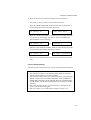
CHAPTER 1 GENERAL provides an overview of the printer. Read this
chapter first to get familiar with the printer.
CHAPTER 2 GETTING STARTED gives you general information about
this printer. Be sure to read this chapter before you use the printer.
CHAPTER 3 BEFORE WORKING WITH THE PRINTER gives you
important information on the printer setup to work with your computer and
software. Be sure to read this chapter before you work with the printer.
CHAPTER 4 CONTROL PANEL details the functions of the panel
switches and lamps.
(Disk)
CHAPTER 5 OPTIONS describes the optional accessories for this
printer.
(Disk)
CHAPTER 6 MAINTENANCE provides guidance on how to maintain
your printer
(Disk)
CHAPTER 7 TROUBLESHOOTING helps you troubleshoot the printer
in case of problems.
APPENDICES contain detailed technical information on the printer as
well as the character sets and a quick reference guide to the printer control
commands.
(Disk)
INDEX provides an alphabetical list of the contents of this manual and the
floppy disk supplied with the printer.
1–1
USER’S GUIDE
✒ Notes
When you read this user’s guide, note the following:
• Chapters 4, 5, 6 and the Appendices of this User’s Guide are on the
floppy disk provided with this printer. Read ABOUT CHAPTERS ON
THE FLOPPY DISK (See page 1-3) carefully before you print out the
additional chapters included on the floppy disk.
• This user’s guide contains instructions or steps to teach you various
operations of the printer. Remember that the instructions start with the
factory settings, particularly in Chapter 2 and Chapter 3. If you change
the settings, particularly the emulation mode, the display messages
change accordingly.
• The paper size has been factory set to letter or A4, depending upon the
final destination of the printer. Some display messages appear
differently in accordance with this setting.
1–2
CHAPTER 1 GENERAL
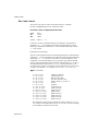
ABOUT CHAPTERS ON THE FLOPPY DISK
■ The floppy disk provided with this printer contains Chapters 4, 5, 6,
and the Appendices of this User’s Guide. Follow the steps below to
install and print out the sections you need to see.
1. Set up your printer referring to CHAPTER 2 GETTING STARTED.
2. Start your computer and MS-DOS® or Windows 95 / Windows 3.1.
3. Insert the printer User’s Guide floppy disk into the floppy disk drive A
of your computer. It is assumed that A: is your floppy disk drive in this
description.
4. Install the Disk Manual into your computer.
(for DOS user)
Type A:\INSTALL and press ENTER key.
Follow the messages on the screen.
(for Windows 95 user)
Click Start and choose Run.
Type A:\SETUP and press the ENTER key.
(for Windows 3.1 user)
Choose the RUN command from the FILE menu in the Program
Manager.
Type A:\SETUP and press the ENTER key.
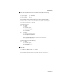
■ Once you installed the Disk Manual into your computer, follow the
steps below to print out the sections you need to see.
Print chapters from the Disk Manual.
(for DOS user)
Type HL1260e or HL1660 and press ENTER key. You do not need to
choose disk drive nor directory. Follow the messages on the screen.
(for Windows 95 user)
Double-click the HL1260e or HL1660 Series folder on the screen, and
then the Disk Manual icon. Follow the messages on the screen.
(for Windows 3.1 user)
Double-click the HL1260e or HL1660 group icon (sign on the screen)
and then the Disk Manual icon. Follow the messages on the screen.
✒ Notes
• You will need a minimum of 6 MB free area on your hard disk drive in
order to print any sections of the User's Guide.
• Use A4 or letter size paper for printing.
1–3
USER’S GUIDE
ABOUT THIS PRINTER
Features
This printer has the following standard features. When you need more
information on how to use a particular feature, turn to the page indicated at
the end of the paragraph.
High Speed and Quiet Laser Printing
This printer uses electrophotography technology by laser beam scanning so
that it can print at a speed of 12 pages per minute. The controller utilizes a
high speed 32-bit RISC microprocessor and special hardware chips. The
quiet printing will not bother you working in your office or at home: max.
49 dB A (printing)/40 dB A (stand-by).
600 DPI Resolution
This printer uses a print engine with a resolution of 600 dots per inch (dpi).
Compared with a 300-dpi engine, the quality of the output is far superior.
See page 4-28. By utilizing the 300-dpi mode, the printer can also print
300-dpi data, if necessary. (In HP emulation you can select a horizontal
1200-dpi mode by special control command. See page Appendix-52.)
High Resolution Control
The high resolution control (HRC) technology provides clear and crisp
printouts and improves even the 600-dpi resolution. See 4-30.
Maintenance-Free Toner Cartridge
The toner cartridge can print up to 6,000 single-sided pages. The one piece,
easy-to-replace toner cartridge does not require difficult maintenance. Just
install it. See 2-7.
Advanced Photoscale Technology
This printer can print graphics in 256 shades of gray in HP® LaserJet 4+™
emulation and BR-Script level 2, producing nearly photographic quality.
1–4
CHAPTER 1 GENERAL
Universal Paper Cassette and Manual Loading
This printer loads paper automatically from the paper cassette. Since the
paper cassette is a universal type, a number of different sizes of paper can
be used. Even envelopes can be loaded from the multi-purpose tray and the
upper paper cassette. In addition, the multi-purpose tray allows you to load
paper sheet by sheet. See 3-15 for auto loading and 3-16 for manual
loading.
Three Interfaces
This printer has a high speed bi-directional parallel interface, an RS-232C
serial interface, and a modular input/output (MIO) compatible interface.
If your application software supports the bi-directional parallel interface,
you can monitor the printer status. It is fully compatible with the
industry-standard bi-directional parallel interface. See page 2-17.
The RS-232C serial interface is an industry standard so that you can
connect it to any computer using a standard serial cable. See page 2-17.
The MIO interface allows you to install a commercial MIO-compatible
card. If you install the card, you can use one more interface port for features
such as networking or printer sharing. See page 5-6.
Automatic Interface Selection
This printer can automatically select the bi-directional parallel, RS-232C
serial, or MIO interface depending on the interface port through which it
receives data. With this feature, the printer can be connected to more than
one computer. See page 3-5.
Five Emulation Modes
This printer can emulate the Hewlett-Packard® laser printer-LaserJet 4+
(PCL® 5e), PostScript® Level 2 language emulation (Brother BR-Script
Level 2) printers, the industry-standard HP-GL™ plotter as well as
EPSON® FX-850™, and IBM® Proprinter XL® printers. You can print
with all application programs that support one of these printers. See page
3-1.
1–5
USER’S GUIDE
Automatic Emulation Selection
This printer can automatically select the printer emulation mode depending
on the print commands it receives from the computer software. With this
feature, many users can share the printer on a network. See page 3-3.
Data Compression Technology
This printer can internally compress the received graphics and font data in
its memory so that it can print larger graphics and more fonts without
additional memory.
Memory Expansion
This printer has 2-Mbyte or 4-Mbyte of RAM as standard. It can be
expanded up to 66 Mbytes. The memory should be expanded to 6 Mbytes in
total or more to enjoy 600-dpi or APT printouts in the BR-Script 2 mode.
When you select duplex mode with an optional duplex unit installed, the
memory should be expanded to 10Mbytes in total or more to enjoy 600-dpi
duplex printing. See pages 4-28 and 5-7. (The standard memory fitted can
vary depending on the printer model and country.)
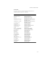
75 Scalable and 12 Bitmapped Fonts
This printer has the following scalable fonts and bitmapped fonts. The fonts
that can be used vary according to the current emulation mode.
■ HP LaserJet 4+, EPSON FX-850, and IBM Proprinter XL Modes See
printed Appendix after Chapter 7.
Scalable Fonts:
Intellifont Compatible Fonts:
• Alaska, Extrabold
• Antique Oakland, Oblique, Bold
• Brougham, Oblique, Bold, BoldOblique
• Cleveland Condensed
• Connecticut
• Guatemala Antique, Italic, Bold, BoldItalic
• Letter Gothic, Oblique, Bold
• Maryland
• Oklahoma, Oblique, Bold, BoldOblique
• PC Brussels Light, LightItalic, Demi, DemiItalic
• PC Tennessee Roman, Italic, Bold, BoldItalic
• Utah, Oblique, Bold, BoldOblique
• Utah Condensed, Oblique, Bold, BoldOblique
1–6
CHAPTER 1 GENERAL
Microsoft® Windows® 3.1 / Windows 95 TrueType™
Compatible Fonts:
• BR Symbol
• Helsinki, Oblique, Bold, BoldOblique
• Tennessee Roman, Italic, Bold, BoldItalic
• W Dingbats
Type 1 Font Compatible Fonts:
• Atlanta Book, BookOblique, Demi, DemiOblique
• Calgary MediumItalic
• Copenhagen Roman, Italic, Bold, BoldItalic
• Portugal Roman, Italic, Bold, BoldItalic
Brother Original Fonts:
• Bermuda Script
• Germany
• San Diego
• US Roman
Bitmapped Fonts (Portrait and Landscape):
• LetterGothic16.66 Medium, Italic, Bold, BoldItalic
• OCR-A
• OCR-B
■ BR-Script 2 Mode
Scalable Fonts:
• Atlanta Book, BookOblique, Demi, DemiOblique
• Alaska, Extrabold
• Antique Oakland, Oblique, Bold
• Bermuda Script
• BR Dingbats
• BR Symbol
• Brougham, Oblique, Bold, BoldOblique
• Brussels Light, LightItalic, Demi, DemiItalic
• Calgary MediumItalic
• Cleveland Condensed
• Connecticut
• Copenhagen Roman, Italic, Bold, BoldItalic
• Germany
• Guatemala Antique, Italic, Bold, BoldItalic
• Helsinki, Oblique, Bold, BoldOblique
• Helsinki Narrow, Oblique, Bold, BoldOblique
• Letter Gothic, Oblique, Bold
• Maryland
• Oklahoma, Oblique, Bold, Bold Oblique
• Portugal Roman, Italic, Bold, BoldItalic
• San Diego
• Tennessee Roman, Italic, Bold, BoldItalic
• US Roman
• Utah, Oblique, Bold, BoldOblique
• Utah Condensed, Oblique, Bold, BoldOblique
1–7
USER’S GUIDE
High Speed Printing with Microsoft Windows 95 / Windows 3.1
Since TrueType compatible fonts are resident in this printer, the printer can
print them with Microsoft Windows 95 / Windows version 3.1 at a high
speed without downloading them. Because the printer has a TrueType Font
rasterizer, it can rasterize fonts at a high speed.
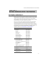
Bar Code Print
This printer can print the following 11 types of bar codes:
•
•
•
•
•
•
Code 39
Interleaved 2 of 5
EAN-8
EAN-13
UPC-A
EAN-128
•
•
•
•
•
UPC-E
Codabar
US-PostNet
ISBN
Code 128
CCITT G3/G4
Since this printer supports the CCITT G3/G4 format in addition to HPcompatible formats, it can quickly receive and print data compressed in this
format.
Lock Panel
If the panel switch settings have been changed, the printer may not work as
you expect. You can lock your settings to prevent changes from being
made. See page 4-41.
Power Save Mode
This printer has a power saving mode. As laser printers consume power to
keep the fixing assembly at a high temperature, this feature can save
electricity when the printer is on but not being used. The factory setting of
the Power Save mode is ON that complies with EPA Energy Star new
specification. Compared with conventional laser printers, this printer
consumes less power even when the power saving mode is turned off. See
page 4-69.
Toner Save Mode
This printer has an economical toner save mode. You can cut your printer
running cost substantially by using this mode in addition to the improved
life expectancy of the toner cartridge. See page 4-69.
1–8
CHAPTER 1 GENERAL
Reprint Function
You can reprint the last page printed with a touch of a panel switch which
allows reprinting without sending the data again from the computer. See
page 4-61.
Flash Memory Card and HDD Card
You can store fonts, macros, logos, and other print data in a commercial
PCMCIA-compatible flash memory card or HDD card that is installed in
the upper card slot of this printer. See pages 4-32 and 5-2.
Saving User Settings
You can operate the printer differently from other users with your own
panel switch settings. Two sets of user settings can be stored. See page 447.
1–9
USER’S GUIDE
Options
The following options are available for this printer:
Lower Tray Unit
A lower tray unit expands the paper source capacity. You can load extra
paper and switch between the upper and lower paper sources automatically.
See page 5-1.
Duplex Unit
A duplex unit enables you to print on both sides of the paper. See page 511.
Technical Reference Manual
The technical reference manual contains detailed information about the
printer control commands. For programming with the printer, see this
manual which is available from your Brother dealer.
The following commercial products can be installed into this printer:
MIO Card
A commercial modular input/output (MIO) compatible sharing/network
card gives you an additional interface port for attaching the printer to a
network or sharing your printer with multiple computers. See page 5-6.
Font Cartridges
Commercial font cartridges containing additional scalable fonts or
bitmapped fonts. See page 5-2.
Flash Memory Card and HDD Card
A commercial flash memory card or a HDD card can be installed. You can
store fonts, macros, logos, and other print data in a commercial PCMCIAcompatible flash memory card or HDD card. See pages 4-32 and 5-2.
RAM Expansion
Installing commercial memory modules expands the memory capacity up
to 66 Mbytes. See pages 5-7.
1–10
CHAPTER 2 GETTING STARTED
CHAPTER 2
GETTING STARTED
BEFORE USING THE PRINTER
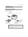
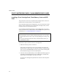
Checking the Components
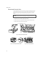
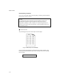
Printer Carton
When you unpack the printer, check to see that you have all of the
following parts.
Power Cord
Printer
Upper Paper Cassette
(installed inside the printer)
User’s Guide Disk
Windows Driver/TrueType
Compatible Font Disk #1
Windows Driver/TrueType
Compatible Font Disk #2
User’s Guide
(this book)
Fig. 2-1 Components in the Printer Carton
✒ Note
An interface cable is not a standard accessory. Please purchase an
appropriate cable according to the interface you intend to use. The power
cord may differ slightly from this figure depending on the country where
you purchased the printer.
2–1
USER’S GUIDE
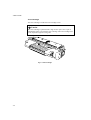
Toner Cartridge
The toner cartridge is inside the toner cartridge carton.
!
Caution
The toner cartridge is packed inside a bag. Do not open it now. Open it
immediately before you install the toner cartridge. The toner cartridge must
not be exposed to light for a long time.
Fig. 2-2 Toner Cartridge
2–2
CHAPTER 2 GETTING STARTED
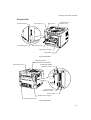
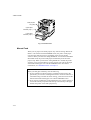
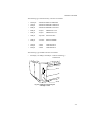
General View
Control Panel
Font/IC Card Slot
Top Cover
Face Down Print
Delivery Tray
A
B
Font Cartridge Slot
Multi-purpose Tray
Upper Paper Cassette
Power Switch
Fig. 2-3 Front View
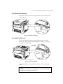
Adjustment Knob for
Face Up/Down Print Delivery
Rear Access Cover
Bi-directional Parallel
Interface Connector
RS-232C Serial
Interface Connector
MIO Card Slot
Modular Jack for Options
Power Cord Connector
Fig. 2-4 Rear View
2–3
USER’S GUIDE
Operating and Storage Environment
Please take note of the following before using the printer.
Power Supply
Use the printer within the specified power range.
AC power:
Frequency:
±10% of the rated power voltage
50 Hz (220-240 V) or 60 Hz (110-120 V)
The power cord, including extensions, should not exceed 5 meters (16.5
feet).
Do not share the same power circuit with other high-power appliances,
particularly an air conditioner, copier, shredder, etc. If it is unavoidable that
you must use the printer with these appliances, we recommend you use a
voltage transformer or a high-frequency noise filter.
Use a voltage regulator if the power source is not stable.
Environment
Use the printer only within the following ranges of temperature and
humidity.
Ambient temperature: 10°C to 32.5°C (50°F to 90.5°F)
Ambient humidity:
20% to 80% (without condensation)
Do not block the air exit on top of the printer. Do not place objects on top of
the printer, especially on the air exit.
Ventilate the room where you use the printer.
Do not place the printer where it is exposed to direct sunlight. Use a blind
or a heavy curtain to protect the printer from direct sunlight if the printer is
unavoidably set up near a window.
Do not install the printer near devices that contain magnets or generate
magnetic fields.
Do not subject the printer to strong physical shocks or vibrations. Do not
expose the printer to open flames or salty or corrosive gasses.
Place the printer on a flat, horizontal surface.
Keep the printer clean. Do not install the printer in a dusty place.
Do not install the printer near an air conditioner.
2–4
CHAPTER 2 GETTING STARTED
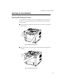
SETTING UP THE PRINTER
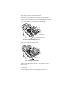
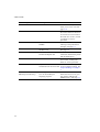
Opening and Closing the Printer
To install the toner cartridge or to access the paper path, you need to open
the top cover of the printer. Remember the following steps to open and
close the printer.
■ To open the printer, hold both sides of the top cover and raise it upwards
until it latches.
Fig. 2-5 Opening the Top Cover
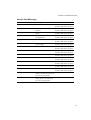
■ To close the printer, lower the top cover and push both sides gently until
it latches.
Fig. 2-6 Closing the Top Cover
2–5
USER’S GUIDE
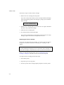
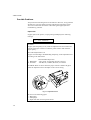
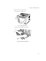
Removing the Protective Parts
After checking that you have all of the correct parts, temporarily place the
printer where you can easily reach all sides. Remove the protective parts
that secure the printer against damage during transportation, as shown
below:
✒ Note
Keep all packing materials for transporting or storing the printer later.
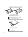
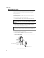
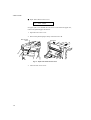
1. Open the top cover and the upper paper cassette.
2. Remove the protective parts from inside the printer and the cassette.
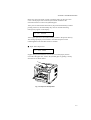
3. Remove both spacers from the fixing roller.
Protective Parts
Fig. 2-7 Removing the Protective Parts
Spacers
Fig. 2-7 Removing the Protective Parts
2–6
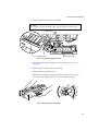
Fig. 2-8 Removing the Spacers
CHAPTER 2 GETTING STARTED
Installing the Toner Cartridge
This printer uses a toner cartridge to print. You have one toner cartridge as
standard. A new cartridge contains enough toner to print approximately
6,000 A4 or letter-size single-sided pages at about 5% coverage (if the print
density is set at level 8).
If you turn on the printer without the toner cartridge installed, the display
shows the following operator call message to prompt you to install the
toner cartridge.
14 NO CARTRIDGE
To install the toner cartridge, follow these steps:
1. Open the top cover of the printer.
2. Open the bag to unpack the toner cartridge.
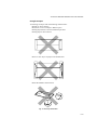
!
•
•
•
•
Caution
Do not expose the toner cartridge to direct light.
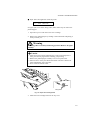
Do not stand the toner cartridge on its end or turn it up-side down.
Do not touch the shaded parts shown below.
Do not open the drum shutter otherwise the toner or drum is adversely
affected and might cause serious damage when printing.
Drum Shutter
Fig. 2-9 Don’ts When Handling the Toner Cartridge
2–7
USER’S GUIDE
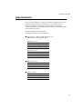
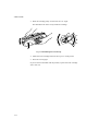
3. Hold the toner cartridge with both hands. Rock it gently several times at
a 45° angle. This distributes the toner evenly inside the cartridge.
45°
45°
Fig. 2-10 Rocking the Toner Cartridge
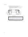
4. Bend the tab up and down several times until it is detached from the
toner cartridge.
Fig. 2-11 Detaching the Tab
2–8
CHAPTER 2 GETTING STARTED
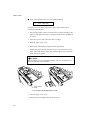
5. Hold the tab firmly and pull it out until the sealing tape comes out all the
way.
Fig. 2-12 Pulling Out the Sealing Tape
!
Caution
If the tab breaks from the sealing tape, hold and pull out the tape. If your
hands or clothes get dirty with toner, wipe or wash it off immediately with
cold water.
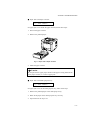
6. Insert the toner cartridge in the direction of the arrows engraved on the
cartridge into the side guides until it stops securely in the cartridge
holder inside the printer.
✒ Note
Push both sides of the toner cartridge gently until the cartridge is seated in
its place.
Fig. 2-13 Inserting the Toner Cartridge
2–9
USER’S GUIDE
7. Close the top cover of the printer.
When the cartridge has almost run out of toner, the display shows the
following operator call message to prompt you to replace the toner
cartridge.
16 TONER EMPTY
Although you can print several pages after the toner empty message
appears, be sure to replace the toner cartridge with a new one before it
becomes completely empty.
✒ Note
You can select the printer’s operation when the “Toner Empty” message is
displayed with the MODE switch. The printer continues or stops printing.
For further information, see “Toner Low” in Chapter 4.
For toner cartridge replacement, see “Toner Cartridge” in Chapter 6.
2–10
CHAPTER 2 GETTING STARTED
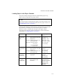
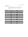
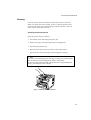
Loading Paper in the Paper Cassette
The printer usually loads paper from the installed multi-purpose tray,
upper cassette or optional lower paper cassette.
✒ Note
The lower tray unit is an option for this printer. This section refers to the
upper paper cassette. For information about the lower paper cassette, see
“LOWER TRAY UNIT” in Chapter 5.
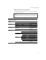
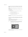
Since the paper cassette is a universal type, you can set letter, A4, legal, ISO
B5, executive, A5, ISO B6, or A6 size cut sheet paper or COM10,
Monarch, C5, DL, or ISO B5 size envelopes in the paper cassette.
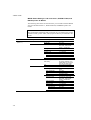
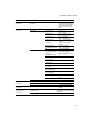
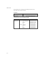
The paper sources have the following limitation. For more information
about paper, see “PRINT MEDIA” in Chapter 3.
paper source
available size
the multipurpose tray
(MP)
cut sheet : letter, legal, A4, ISO
B5, Executive, A5, ISO
B6 and A6
envelope: COM 10, Monarch, C5,
DL and ISO B5
other size: wide 90-216mm
(3.5”-8.5”)
long 148-356mm
(5.8”-14”)
cut sheet : letter, legal, A4, ISO
B5, Executive, A5, ISO
B6 and A6
envelope :COM 10, Monarch, C5,
DL and ISO B5
cut sheet : letter, legal, A4,
Executive
the upper
paper cassette
(T1)
the optional
lower paper
cassette (T2)
all sources
for duplex
printing (DX)
cut sheet : letter, legal, A4, ISO
B5(except T2) and
Executive
available type and
capacity
plain paper : 150
envelope : 15
OHP film : 100
label stock : 100
other type : weight =
60 to 135 g/m2
(16 to 36 lbs)
plain paper : 500
weight =
60 to 105 g/m2
(16 to 28 lbs)
envelope : 40
plain paper : 500
weight =
60 to 90 g/m2
(16 to 24 lbs)
* The capacity of T1
is reduced from
the above specified
capacities with
the duplex unit
installed.
2–11
USER’S GUIDE
Follow these steps to set paper and install the paper cassette:
✒ Note
Be sure to select the same paper size as the paper to be used from your
application software, or correct printing cannot be obtained.
If your application software does not support paper size selection on its
print menu, you can change the paper size with the MODE switch in the
FORMAT MODE. For paper size change, see “MODE Switch” in Chapter
4.
The paper size has been factory set to letter or A4, depending upon the final
destination of the printer.
•110/120V model: Letter size paper set.
•220/240V model: A4 size paper set.
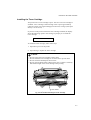
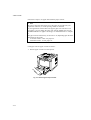
Load paper into the paper cassette as follows:
1. Pull the paper cassette out of the printer.
Fig. 2-14 Removing the Paper Cassette
2–12
CHAPTER 2 GETTING STARTED
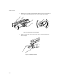
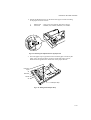
2. Switch the adjustment lever on the back of the paper cassette according
to the paper size shown below.
I.
II.
Backwards
Forwards
: letter, legal, A4, ISO B5, Executive and A5
: ISO B6, A6, COM10, Monarch, C5 and DL
Fig. 2-15 Switching the Adjustment lever by Paper Size
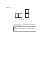
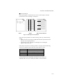
3. Set a side paper stop at right front corner inside the paper cassette by the
paper size to be used so that 2 projectors of the side paper stop are
inserted into the guide holes on the base of the paper cassette.
Letter and
Legal
A4
Executive
ISO B5
A5
Side Paper Stop
Fig. 2-16 Setting the Side Paper Stop
2–13
USER’S GUIDE
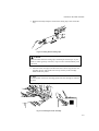
4. Slightly lift the edge of the sliding guides and move them separately so
as to match the size of paper to be used. Match the paper length first and
then the paper width when setting for larger size paper. Match the paper
width first and then the paper length when setting for smaller size paper.
Fig. 2-17 Adjusting the Paper Cassette Sizes
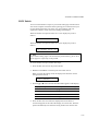
5. Load paper into the paper cassette as shown below.
✒ Note
Do not load more than 500 sheets of paper (80 g/m2or 20 lbs.) in the
cassette, or paper jams may occur. Paper (80 g/m2 or 20 lbs.) should be
loaded up to the arrow head marked on the sliding guide.
Fig. 2-18 Loading Paper into the Cassette
6. Install the paper cassette into the printer.
✒ Note
You can check the remaining paper with the paper indicator located on the
front right of the paper cassette.
2–14
CHAPTER 2 GETTING STARTED
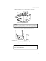
1. Open the multi-purpose tray by pressing the front door of the tray
lightly and lowering it gently.
✒ Note
Pull out the extension tray of the multi-purpose tray for long paper if it is
necessary.
Fig. 2-19 Opening the Multi-purpose Tray
and Pulling Out the Extension Tray
2. Lift up and slide the paper width guide to the far right side.
3. Place a stack of paper or envelopes on the tray until it is securely seated.
✒ Notes
When you place paper on the multi-purpose tray, note the following:
• The print surface must be face up.
• The leading edge must be placed inside first and lightly against the
printer.
• The left side must be aligned with the left guide.
• The top of the paper stack must be under the holders on both sides of the
tray. The maximum thickness is 16.5 mm or 0.65 inches.
2–15
USER’S GUIDE
Fig. 2-20 Placing Paper on the Multi-purpose Tray
4. Lift up and slide the paper width guide to match the paper width, so that
it lightly touches the right side of the paper stack.
!
Caution
• Make sure that the neatly stacked paper is correctly seated on the
multi-purpose tray, otherwise paper may not be fed correctly, resulting
in a skewed printout or a paper jam.
• When printing, the inside tray automatically rises to feed paper into the
printer.
2–16
CHAPTER 2 GETTING STARTED
Connecting the Printer to Your Computer
This printer has a bi-directional parallel interface and an RS-232C serial
interface. They allow the printer to communicate with IBM/PC® or
compatible computers. Before connecting the printer and computer, you
need to purchase or make a connecting cable specifically for the interface
to be used. See “INTERFACE SPECIFICATIONS” in Appendix.
Since the automatic interface selection mode has been factory set, simply
connect the interface cable to the printer. In some cases, you need to turn
off the high-speed and bi-directional parallel communications with the
MODE switch. For further information, see “MODE Switch” in Chapter 4.
When you use the serial interface, you need to have the same
communications settings on both the printer and computer. Since the
automatic interface selection mode has been factory set with certain factory
settings (baud rate = 9600, code type = 8 bits, parity = none, stop bit = 1,
Xon/Xoff = ON, DTR (ER) = ON, and Robust Xon = ON), you may simply
connect the interface cable if these are the same as the settings on your
computer. When necessary, set the communications parameters with the
MODE switch on the printer. For further information, see “MODE Switch”
in Chapter 4. For the settings on the computer, see the manual of the
computer or software you use.
Connect the printer to your computer as follows:
1. Make sure that both the computer and the printer are turned off.
!
Caution
Always turn off the printer and computer when connecting and
disconnecting the cable.
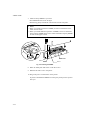
2. Connect one end of the interface cable to the interface connector
located on the back of the printer.
2–17
USER’S GUIDE
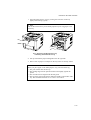
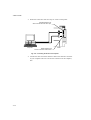
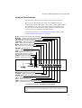
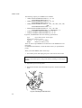
3. Secure the connection with wire clips or screws on the printer.
Parallel Interface Port
Secure connection with wire clips.
Computer
Printer
Serial Interface Port
Secure connection with screws.
Fig. 2-21 Connecting the Printer and Computer
4. Connect the other end of the interface cable to the interface connector
on your computer. Be sure to secure the connection on the computer,
also.
2–18
CHAPTER 2 GETTING STARTED
Turning the Printer On and Off
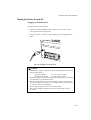
Plugging in the Power Cord
Plug in the power cord as follows:
1. Make sure that the POWER switch is OFF “O”: the switch is on the
front right hand side of the printer.
2. Attach the power cord to the printer and plug it into an appropriate AC
outlet.
Fig. 2-22 Plugging in the Power Cord
!
Caution
• Check the AC voltage. This printer should be operated at the specified
•
•
•
•
voltage and frequency.
• USA and Canada:
AC 110 to 120 V, 60 Hz
• Europe and Australia:
AC 220 to 240 V, 50 Hz
Since this printer must be electrically grounded, the power cord should
be connected to a grounded AC outlet.
The total length of the power cord, including extension cords, should
not exceed 5 meters (16.4 feet). Use of a longer power cord may result
in reduced voltage or malfunctions.
Do not unplug the power cord to turn off the printer.
The printer should be installed near a power outlet which is easily
accessible.
2–19
USER’S GUIDE
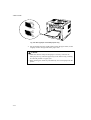
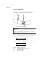
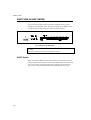
Pressing the POWER Switch
The POWER switch is on the front right hand side of the printer. Pressing
the ON side “ | ” supplies power to the printer, which then performs a self
test and warm up. Pressing the OFF side “O” turns the power off.
ON
OFF
Fig. 2-23 Pressing the POWER Switch
!
Caution
Always wait at least 2 seconds after turning off the power before turning it
back on.
Do not turn the power off while the printer is printing, as this may cause a
paper jam and adversely affect the printer.
The printer performs a self-diagnosis at start-up to check its hardware and
software. If the printer should find any problems, the display will show the
corresponding message. See “TROUBLESHOOTING” in Chapter 7.
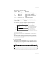
04 SELF TEST
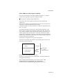
The display shows several messages quickly at start-up. If the printer
detects no errors, it automatically goes on-line and the message changes to
show the current printer status and settings.
LJ READY 001P T1
LJ :
The auto emulation selection is set and currently the HP
LaserJet 4+ emulation mode is selected.
READY : The printer is ready to print.
001 :
The number of copies to print is set to 1.
P:
Portrait print is selected.
T1 :
Paper is fed from Tray1.
2–20
CHAPTER 2 GETTING STARTED
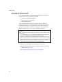
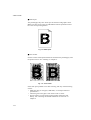
Printing the Test Patterns or Lists
You can check print quality and print a list of available fonts before you
actually start working with the printer. To do so, follow these steps:
1. Make sure that you have already set the toner cartridge and loaded
paper into the cassette or the multi-purpose tray.
2 Turn on the printer. Wait until the display shows the message as
follows.
LJ READY 001P T1
or
LJ READY 001P MP
3. Press the SEL switch to set the printer off-line.
The ON LINE lamp goes off.
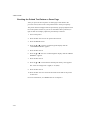
4. Hold down the SHIFT switch and press the TEST switch.
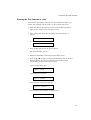
5. Press the ▲ or ▼ switch to scroll through the display until the desired
message appears. To print your selection, press the SET switch.
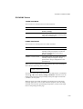
Choose from one of the following selections :
To print out the demo page,
DEMO PAGE
To print out the test pattern,
TEST PRINT
To print out the list of printer settings,
PRINT CONFIG
To print out the list of internal or resident fonts,
PRINT FONTS I
2–21
USER’S GUIDE
To print out the list of optional cartridge/card fonts,
PRINT FONTS C
To print out the list of permanent download fonts,
PRINT FONTS P
To exit from the test mode,
exit
✒ Notes
The messages “PRINT FONTS C” or “PRINT FONTS P” appear only
when an optional font cartridge/card is installed in the font slot or the
permanent download fonts are stored in printer memory respectively.
• If the optional font cartridge/card is installed, you can print out a list of
optional fonts. Since the list shows the ID numbers specific to each
optional font, it helps you to select them with the FONT switch. For
further information, see “FONT Switch” in Chapter 4 and “FONT
CARTRIDGE/CARD, FLASH MEMORY/HDD CARD” in Chapter 5.
• If user-defined characters are already downloaded into the printer
memory as permanent download fonts, you can print out a list of them.
For further information, see “FONT Switch” in Chapter 4.
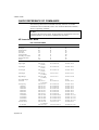
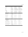
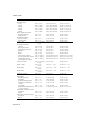
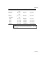
2–22
CHAPTER 2 GETTING STARTED
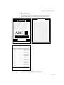
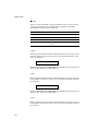
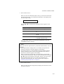
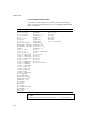
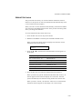
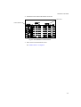
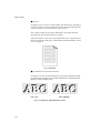
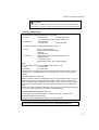
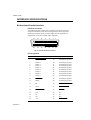
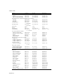
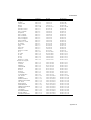
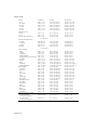
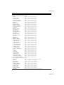
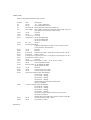
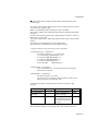
6. Press the SET switch.
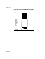
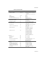
The printer starts printing the selected test pattern or list. When the
printer finishes printing, it automatically exits to the off-line state.
PRINT CONFIGURAITION(1/2)
(LJ):HP LaserJet 4
(FX):EPSON FX-850
TEST PRINT
(BS):BR-Script 2
(GL):HP-GL
(PR):IBMProprinterXL
PAGE COUNTER
RAM SIZE
!"#$%&'()*+,-./1234567890:;@ABCDEFGHIJKLMNOPQRSTUVWXYZ[\]^_`abcdefghijklmnopqrstuvwxyz[|
"#$%&'()*+,-./1234567890:;@ABCDEFGHIJKLMNOPQRSTUVWXYZ[\]^_`abcdefghijklmnopqrstuvwxyz{\}
#$%&'()*+,-./1234567890:;@ABCDEFGHIJKLMNOPQRSTUVWXYZ[\]^_`abcdefghijklmnopqrstuvwxyz{\}~
$%&'()*+,-./1234567890:;@ABCDEFGHIJKLMNOPQRSTUVWXYZ[\]^_`abcdefghijklmnopqrstuvwxyz{\}~!
%&'()*+,-./1234567890:;@ABCDEFGHIJKLMNOPQRSTUVWXYZ[\]^_`abcdefghijklmnopqrstuvwxyz{\}~!"
&'()*+,-./1234567890:;@ABCDEFGHIJKLMNOPQRSTUVWXYZ[\]^_`abcdefghijklmnopqrstuvwxyz{\}~!"#
'()*+,-./1234567890:;@ABCDEFGHIJKLMNOPQRSTUVWXYZ[\]^_`abcdefghijklmnopqrstuvwxyz{\}~!"#$
()*+,-./1234567890:;@ABCDEFGHIJKLMNOPQRSTUVWXYZ[\]^_`abcdefghijklmnopqrstuvwxyz{\}~!"#$%
)*+,-./1234567890:;@ABCDEFGHIJKLMNOPQRSTUVWXYZ[\]^_`abcdefghijklmnopqrstuvwxyz{\}~!"#$%&
*+,-./1234567890:;@ABCDEFGHIJKLMNOPQRSTUVWXYZ[\]^_`abcdefghijklmnopqrstuvwxyz{\}~!"#$%&'
+,-./1234567890:;@ABCDEFGHIJKLMNOPQRSTUVWXYZ[\]^_`abcdefghijklmnopqrstuvwxyz{\}~!"#$%&'(
,-./1234567890:;@ABCDEFGHIJKLMNOPQRSTUVWXYZ[\]^_`abcdefghijklmnopqrstuvwxyz{\}~!"#$%&'()
-./1234567890:;@ABCDEFGHIJKLMNOPQRSTUVWXYZ[\]^_`abcdefghijklmnopqrstuvwxyz{\}~!"#$%&'()*
./1234567890:;@ABCDEFGHIJKLMNOPQRSTUVWXYZ[\]^_`abcdefghijklmnopqrstuvwxyz{\}~!"#$%&'()*+
/1234567890:;@ABCDEFGHIJKLMNOPQRSTUVWXYZ[\]^_`abcdefghijklmnopqrstuvwxyz{\}~!"#$%&'()*+,
1234567890:;@ABCDEFGHIJKLMNOPQRSTUVWXYZ[\]^_`abcdefghijklmnopqrstuvwxyz{\}~!"#$%&'()*+,234567890:;@ABCDEFGHIJKLMNOPQRSTUVWXYZ[\]^_`abcdefghijklmnopqrstuvwxyz{\}~!"#$%&'()*+,-.
34567890:;@ABCDEFGHIJKLMNOPQRSTUVWXYZ[\]^_`abcdefghijklmnopqrstuvwxyz{\}~!"#$%&'()*+,-./
4567890:;@ABCDEFGHIJKLMNOPQRSTUVWXYZ[\]^_`abcdefghijklmnopqrstuvwxyz{\}~!"#$%&'()*+,-./1
567890:;@ABCDEFGHIJKLMNOPQRSTUVWXYZ[\]^_`abcdefghijklmnopqrstuvwxyz{\}~!"#$%&'()*+,-./12
67890:;@ABCDEFGHIJKLMNOPQRSTUVWXYZ[\]^_`abcdefghijklmnopqrstuvwxyz{\}~!"#$%&'()*+,-./123
7890:;@ABCDEFGHIJKLMNOPQRSTUVWXYZ[\]^_`abcdefghijklmnopqrstuvwxyz{\}~!"#$%&'()*+,-./1234
890:;@ABCDEFGHIJKLMNOPQRSTUVWXYZ[\]^_`abcdefghijklmnopqrstuvwxyz{\}~!"#$%&'()*+,-./12345
90:;@ABCDEFGHIJKLMNOPQRSTUVWXYZ[\]^_`abcdefghijklmnopqrstuvwxyz{\}~!"#$%&'()*+,-./123456
ABC
< EMULATION >
EMULATION
AUTO TIME OUT
EPSON/IBM
KEEP PCL
< MODE >
- INTERFACE MODE I/F
AUTO TIME OUT
PRL SETTING
HIGH SPEED
BI-DIR
RS-232C SETTING
BaundRate
CodeType
Parity
Stop Bit
Xon/Xoff
DTR(ER)
Robust Xon
- FORMAT MODE ORIENTATION
AUTO MODE
(LJ)
AUTO LF
AUTO CR
AUTO WRAP
AUTO SKIP
(FX)
AUTO LF
AUTO MASK
(PR)
AUTO LF
AUTO CR
AUTO MASK
PAGE FORMAT MODE
X OFFSET
Y OFFSET
PAPER
(LJ)
LEFT M
RIGHT M
TOP M
BOTTOM M
LINES
(FX)
LEFT M
RIGHT M
TOP M
BOTTOM M
LINES
(PR)
LEFT M
RIGHT M
TOP M
BOTTOM M
LINES
- RESOLUTION MODE RESOLUTION
HRC
TEST PRINT
= 682
= 10Mbyte
USER SETTINGS
SETTING1
SETTING2
AUTO LaserJet4
5
EPSON
OFF
AUTO LaserJet4
5
EPSON
OFF
AUTO LaserJet4
5
EPSON
OFF
PARALLEL
5
<<-
<<-
ON
ON
<<-
<<-
9600
8
NONE
1
ON
ON
OFF
<<<<<<<-
<<<<<<<-
PORTRAIT
<-
<-
OFF
OFF
OFF
ON
OFF
OFF
OFF
ON
OFF
OFF
OFF
ON
OFF
OFF
OFF
OFF
OFF
OFF
OFF
OFF
OFF
OFF
OFF
OFF
OFF
OFF
OFF
(dots)
(dots)
0
0
A4
<<A4
<<A4
(C)
(C)
(")
(")
(L)
0
78
0.5
0.5
64
0
78
0.5
0.5
64
0
78
0.5
0.5
64
(C)
(C)
(")
(")
(L)
0
80
.33
.33
66
0
80
.33
.33
66
0
80
.33
.33
66
(C)
(C)
(")
(")
(L)
0
80
.33
.33
66
0
80
.33
.33
66
0
80
.33
.33
66
600
MEDIUM
<<-
<<-
(S)
(S)
(BAUD)
(bits)
(bits)
(DPI)
PRINT CONFIG
PORTRAIT LIST
INTERNAL FONT
NUMBER SYMBOL SET
(ID) PITCH SIZE
I000
I001
I002
I003
I004
I005
I006
I007
I008
I009
I010
I011
I012
I013
I014
I015
I016
I017
STYLE
8U:ROMAN 8...
P: Scalable
Upright(0)
ESC(IDESC(s1p#v0s0b4101T
8U:ROMAN 8...
P: Scalable
Upright(0)
ESC(IDESC(s1p#v0s3b4101T
8U:ROMAN 8...
P: Scalable
Italic(1)
ESC(IDESC(s1p#v1s0b4101T
8U:ROMAN 8...
P: Scalable
Italic(1)
ESC(IDESC(s1p#v1s3b4101T
8U:ROMAN 8...
P: Scalable
Upright(0)
ESC(IDESC(s1p#v0s0b4113T
8U:ROMAN 8...
P: Scalable
Upright(0)
ESC(IDESC(s1p#v0s3b4113T
8U:ROMAN 8...
P: Scalable
Italic(1)
ESC(IDESC(s1p#v1s0b4113T
8U:ROMAN 8...
P: Scalable
Italic(1)
ESC(IDESC(s1p#v1s3b4113T
8U:ROMAN 8...
P: Scalable
Italic(1)
ESC(IDESC(s1p#v1s0b4116T
8U:ROMAN 8...
P: Scalable
Upright(4)
ESC(IDESC(s1p#v4s3b4140T
8U:ROMAN 8...
P: Scalable
Upright(0)
ESC(IDESC(s1p#v0s-3b4143T
8U:ROMAN 8...
P: Scalable
Upright(0)
ESC(IDESC(s1p#v0s2b4143T
8U:ROMAN 8...
P: Scalable
Italic(1)
ESC(IDESC(s1p#v1s-3b4143T
8U:ROMAN 8...
P: Scalable
Italic(1)
ESC(IDESC(s1p#v1s2b4143T
8U:ROMAN 8...
P: Scalable
Upright(0)
ESC(IDESC(s1p#v0s0b4148T
8U:ROMAN 8...
P: Scalable
Upright(0)
ESC(IDESC(s1p#v0s3b4148T
8U:ROMAN 8...
P: Scalable
Italic(1)
ESC(IDESC(s1p#v1s0b4148T
8U:ROMAN 8...
P: Scalable
Italic(1)
ESC(IDESC(s1p#v1s3b4148T
WEIGHT
TYPEFACE
F
O
N
T
S
A
M
P
L
E(600dpi)
Medium(0)
ABCDefgh123?!"#$%&'()<>/012
Bold(3)
ABCDefgh123?!"#$%&'()<>/01
PcTENNES Reg (4101)
(#:point size 0.25 - 999.75)
PcTENNES Bd
(4101)
(#:point size 0.25 - 999.75)
Midium(0)
ABCDefgh123?!"#$%&'()<>/012
Bold(3)
ABCDefgh123?!"#$%&'()<>/012
PcTENNES It
(4101)
(#:point size 0.25 - 999.75)
PcTENNES BdIt (4101)
(#:point size 0.25 - 999.75)
Medium(0)
ABCDefgh123?!"#$%&'()<>/0
Bold(3)
ABCDefgh123?!"#$%&'()<>/0
OKLAHOMA Reg (4113)
(#:point size 0.25 - 999.75)
OKLAHOMA Bd
(4113)
(#:point size 0.25 - 999.75)
Medium(0)
ABCDefgh123?!"#$%&'()<>/0
Bold(3)
ABCDefgh123?!"#$%&'()<>/0
OKLAHOMA It
(4113)
(#:point size 0.25 - 999.75)
OKLAHOMA BdIt (4113)
(#:point size 0.25 - 999.75)
Medium(0)
CONNECTICUT
(4116)
(#:point size 0.25 - 999.75)
Bold(3)
Light(-3)
CLEVELAND Cd (4140)
(#:point size 0.25 - 999.75)
Bold(2)
PcBRUSSEL Lt (4143)
(#:point size 0.25 - 999.75)
Light(-3)
PcBRUSSEL Bd (4143)
(#:point size 0.25 - 999.75)
Bold(2)
PcBRUSSEL LtIt(4143)
(#:point size 0.25 - 999.75)
PcBRUSSEL BdIt(4143)
(#:point size 0.25 - 999.75)
ABCDefgh123?!"#$%&'()<>/0123456
ABCDefgh123?!"#$%&'()<>/
ABCDefgh123?!"#$%&'()<>/
ABCDefgh123?!"#$%&'()<>
ABCDefgh123?!"#$%&'()<>/
ABCDefgh123?!"#$%&'()<>
Medium(0)
ABCDefgh123?!"#$%&'()<>/01
Bold(3)
ABCDefgh123?!"#$%&'()<>/0
UTAH Reg
(4148)
(#:point size 0.25 - 999.75)
UTAH Bd
(4148)
(#:point size 0.25 - 999.75)
Medium(0)
ABCDefgh123?!"#$%&'()<>/01
Bold(3)
ABCDefgh123?!"#$%&'()<>/0
UTAH It
(4148)
(#:point size 0.25 - 999.75)
UTAH BdIt
(4148)
(#:point size 0.25 - 999.75)
ID:Symbol Set ID
PRINT FONTS I
Fig. 2-24 Test Pattern, Setting List, and Font List
2–23
USER’S GUIDE
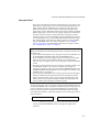
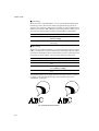
Checking the Printed Test Pattern or Demo Page
After you print out the test pattern or demo page as described in the
previous section, take a look at the printed sheet to check print quality.
The printer has been shipped with the print density properly adjusted with
the control panel switches. If you are not satisfied with the printout (too
light or dark for example), adjust the print density as follows:
1. Turn on the printer.
2. Press the SEL switch to set the printer off-line state.
3. Press the MODE switch.
4. Press the ▲ or ▼ switch to scroll through the display until the
“ADVANCED MODE” appears.
5. Press the SET switch.
6. Press the ▲ or ▼ switch to scroll through the display until the “PRINT
DENSITY” appears.
7. Press the SET switch.
8. Press the ▲ or ▼ switch until the desired print density value appears.
The value can change from 1 (light) to 15 (dark).
9. Press the SET switch.
10. Press the SEL switch to exit from the mode menus and set the printer
on-line state.
For more information, see “MODE Switch” in Chapter 4.
2–24
CHAPTER 3 BEFORE WORKING WITH THE PRINTER
CHAPTER 3
BEFORE WORKING WITH THE PRINTER
SOFTWARE COMPATIBILITY
Before working with your application software, you need to set up or install
the printer driver in your software. Locate the printers that your application
software supports and install the desired printer driver. Each software
package differs in the way the printer driver is selected. Read the software
manual and follow the setup or installation procedures.
Be sure to select the printer emulation mode that matches the installed
printer driver. This printer emulates particular printer models of the
following manufacturers. Since this printer has been factory set with the
automatic emulation selection on, you may not need to select the emulation
mode. When necessary, select the appropriate printer emulation mode with
the panel switches according to the printer driver installed in your
application software. See “CHAPTER 4 CONTROL PANEL.”
Printer Driver
Emulation Mode
*
*
HL-1660
HL-1260e
HL-1260
HL-10h
HP LaserJet 4+
HL-10V/DV
HP LaserJet III™
HP LaserJet IIID™
HP LaserJet Series II™
HP LaserJet IID™
HP LaserJet Plus™
HP LaserJet 4+
HP LaserJet 4+
HP LaserJet 4+
HP LaserJet 4+
HP LaserJet 4+
HP LaserJet 4+
HP LaserJet 4+
HP LaserJet 4+
HP LaserJet 4+
HP LaserJet 4+
HP LaserJet 4+
*
*
HL-1660 (BR-Script 2)
HL-1260e (BR-Script 2)
HL-1260 (BR-Script 2)
BR-Script 2
BR-Script 2
BR-Script 2
PostScript® level 2 language printer
HL-10h (BR-Script)
HL-10PS/DPS
HL-8PS
Apple® LaserWriter® II NT/NTX
BR-Script 2
BR-Script 2
BR-Script 2
BR-Script 2
BR-Script 2
PostScript® language printer
BR-Script 2
*
HP 7475A™
HP-GL™
HP-GL
HP-GL
*
EPSON FX-850
EPSON FX-80™
EPSON FX-850
EPSON FX-850
*
IBM Proprinter XL
IBM Proprinter ®
IBM Proprinter XL
IBM Proprinter XL
3–1
USER’S GUIDE
To get the most out of this printer, you need to install the printer driver for
this printer or the HP LaserJet 4+ and select the HP LaserJet 4+ emulation
mode: this is the best combination. When any other HP LaserJet series
printer driver is installed, select the HP LaserJet 4+ emulation mode. When
any other printer driver is installed, select the HP-GL, BR-Script 2,
EPSON, or IBM emulation mode according to the installed printer driver.
You may find difficulty in printing EPS file format pictures with the HP
LaserJet 4+ mode. In this case, it is better to select the BR-Script 2 mode.
An asterisk (*) indicates the best or recommended combination of the
printer driver and emulation mode. Be sure to use any of these best or
recommended combinations if circumstances permit. When an emulation
mode other than the HP mode or BR-Script 2 is selected, the printout may
differ slightly from the printout that the target printer produces.
For Windows 95 or Windows 3.1 users, to get the best performance from
your printer, install the driver supplied with your printer.
3–2
CHAPTER 3 BEFORE WORKING WITH THE PRINTER
AUTOMATIC EMULATION SELECTION
This printer has an automatic emulation selection function. When the
printer receives data from the computer, it automatically selects the
emulation mode. This function has been factory set to ON.
The printer can select the emulation among the following combinations:
EPSON/IBM Priority
Auto Selection Mode
EPSON (default)
HP LaserJet 4+
BR-Script 2
HP-GL
EPSON FX-850
IBM
HP LaserJet 4+
BR-Script 2
HP-GL
IBM Proprinter XL
To get the most out of this laser printer, we recommend you use the HP
LaserJet 4+ emulation mode, which is a true laser printer mode. Since the
HP LaserJet 4+ mode takes the highest priority in the automatic emulation
selection, you can start using the printer as it is with the factory settings in
most cases.
When the automatic emulation selection is active, you can check the
current emulation on the display. When the printer is in ready, print, or wait
states, the display reads as follows:
Emulation
HP LaserJet 4+
BR-Script 2
HP-GL
EPSON FX-850
IBM Proprinter XL
Status Display in Ready State
LJ
BS
GL
FX
PR
READY
IDLE
READY
READY
READY
001P
001P
001P
001P
001P
T1
T1
T1
T1
T1
To select the emulation mode manually, use the EMULATION switch. For
further information, see “EMULATION Switch” in Chapter 4.
3–3
USER’S GUIDE
✒ Notes
When you use the automatic emulation selection, note the following:
• Once the emulation is automatically changed, it is not changed again
for a short period of time. This time period is called “Time Out” and it
can be set with the EMULATION switch. The factory setting is 5
seconds.
• The EPSON or IBM emulation mode priority must be selected, as the
printer cannot distinguish between them. Since the factory setting is the
EPSON emulation mode, you might need to select the IBM emulation
mode with the EMULATION switch when you need to use this
emulation..
• Try this function with your application software or network server. If
the function does not work properly, select the required emulation mode
manually using the printer panel switches or use emulation selection
commands from your software.
3–4
CHAPTER 3 BEFORE WORKING WITH THE PRINTER
AUTOMATIC INTERFACE SELECTION
This printer has an automatic interface selection function. When the printer
receives data from the computer, it automatically selects the bi-directional
parallel, RS-232C serial interface, or MIO interface as appropriate.
When you use the parallel interface, you can turn the high-speed and bidirectional parallel communications on or off with the MODE switch. For
further information, see “MODE Switch” in Chapter 4. Since the automatic
interface selection mode has been factory set to ON, simply connect the
interface cable to the printer.
When you use the serial interface, you need to have the same
communications settings on both the printer and computer. Since the
automatic interface selection mode has been factory set with certain
settings, you may be able to simply connect the interface cable to the
printer if your computer has the settings listed below.
Communications Parameters
Baud rate (data transfer speed)
Code type (data length)
Parity (data error check)
Stop bit (data separator)
Xon/Xoff (handshake protocol)
DTR (ER)
Robust Xon
Factory Settings
9600
8 bits
None
1 stop bit
ON
ON
OFF
If a commercial interface card has been installed in the MIO card slot, it can
be selected automatically.
When necessary, select the interface or the serial communications
parameters manually with the MODE switch (INTERFACE MODE) on the
printer. For further information, see “MODE Switch” in Chapter 4. For the
settings on the computer, see the manual of the computer or software you
are using.
3–5
USER’S GUIDE
✒ Notes
When you use the automatic interface selection, note the following:
• Once the interface is automatically changed, it is not changed again for
a short period of time. This time period is called “Time Out” and it can
be set with the MODE switch. The factory setting is 5 seconds.
• The communications parameters [ baud rate, code type, parity, stop bit,
Xon/Xoff, DTR(ER), and Robust Xon] must be set for the serial
interface. Although they have been factory set as shown in the above
table, you may need to change them with the MODE switch.
• This function takes a few seconds to work. If you want to speed up
printing, select the required interface manually with the MODE switch.
If you constantly use only one interface, we recommend that you select that
interface in the interface mode. The printer allocates all of the input buffer
to that interface if only one interface is selected.
3–6
CHAPTER 3 BEFORE WORKING WITH THE PRINTER
ABOUT THE CONTROL PANEL
Adjusting the Control Panel Angle
You can adjust the control panel to the desired angle, so you can easily read
the display messages.
To adjust the angle of control panel, gently pinch the tab on the right side of
the panel and move the control panel up and down.
Fig. 3-1 Adjusting the Control Panel Angle
3–7
USER’S GUIDE
Selecting the Local Language Display
The display usually shows the current printer status. When you operate the
control panel switches, it shows functions and settings. If any trouble
occurs, it shows the corresponding error message. You can see these
messages in several languages. The default language is English.
• English
• French
• German
• Dutch
• Spanish
• Italian
• Norwegian
• Finnish
• Danish
• Portuguese
To change to another language:
1. Turn off the printer.
2. Hold down the FORM FEED switch and turn on the printer.
The message “SELF TEST” appears and then the message changes to
“LANG.=ENGLISH * ”.
3. Press the ▲ or ▼ switch until your desired language appears on the
display.
4. Press the SET switch to make the selected language message effective.
An asterisk (*) appears at the end of the display for a short time, and
then the printer automatically returns to on-line state with the selected
language message on the display.
3–8
CHAPTER 3 BEFORE WORKING WITH THE PRINTER
Using the Panel Switches
The printer has a versatile control panel. It has two operation modes:
When you press the switches, they work in the NORMAL mode as
indicated above the switches. When you press the switches with the SHIFT
switch held down, they work in the SHIFT mode as indicated below the
switches. You can control the basic printer operations and make various
printer settings in the NORMAL and SHIFT modes.
For further information, see “SWITCHES IN NORMAL MODE” and
“SWITCHES IN SHIFT MODE” in Chapter 4.
▲ (UP) – Forward scroll through modes and settings.
▼ (DOWN) – Reverse scroll through modes and settings.
CONTINUE – Ignores the error and resumes operation.
SET – Sets selected mode and functions.
FORM FEED – Prints out remaining data or reprints the same page.
FONT – Selects font and character set.
MODE – Sets functions in various modes.
SEL – Selects on-line or off-line state.
ON LINE – Lights when printer is in
the on-line state.
READY – Lights when printer is ready to print.
DATA – Blinks when data is being
received and lights when unprinted
data remains in printer memory.
ALARM – Lights if any errors occur.
Display – Shows various messages.
EMULATION – Selects printer emulation.
ECONOMY – Selects toner save or power save mode.
FEEDER – Selects paper source and media type to be used and
duplex printing.
COPY – Sets the number of copies to print.
SHIFT – Shifts switch operation.
RESET – Resets printer or restores to factory settings.
TEST – Prints self-test pattern or fonts.
Fig. 3-2 Switch Operation in NORMAL and SHIFT Modes
✒ Note
When the printer is in use in the BR-Script 2 mode, some switches are not
used.
3–9
USER’S GUIDE
Printer Settings
You may operate the printer with the panel switch settings unchanged.
They have been factory set. When necessary, change and store them in the
printer memory as user settings.
There are two types of printer settings available on this printer:
1. User Settings
2. Factory Settings
Remember that the user settings override the factory settings. The user
settings are effective until other settings are made or they are restored to the
factory settings.
User Settings
Although the printer settings have been factory set, you can change them
with the control panel switches. Since this printer has a memory, you can
store the panel switch settings in the memory as “User Settings.” They are
recalled every time you turn on the printer.
In addition to the current settings, you can save two more sets of user
settings with the MODE switch and restore to them with the RESET switch.
The current settings are cleared after restoring one of the saved user
settings.
Factory Settings
The printer settings have been set at the factory before shipment. They are
called “Factory Settings.” Although you can operate the printer with these
factory settings unchanged, you can tailor the printer by making user
settings.
✒ Note
Changing the user settings does not affect factory settings. You cannot
modify the preset factory settings.
The changed user settings can be restored to the factory default settings
with the RESET switch. For further information, see “RESET Switch” in
Chapter 4.
3–10
CHAPTER 3 BEFORE WORKING WITH THE PRINTER
PAPER HANDLING
Print Media
Paper Size
1. The upper paper cassette
Since the paper cassette is a universal type, you can use any of the sizes of
paper in the list. The cassette can hold up to 500 sheets of paper (80 g/m2 or
20 lbs.) or up to 40 envelopes (Paper should only be loaded up to the arrow
head marked on the sliding guide).
2. The multi-purpose tray
The multi-purpose tray is the most useful feeder for you to handle many
types of paper. The multi-purpose tray can hold up to 150 sheets of paper
(80 g/m2 or 20 lbs.) or up to 15 envelopes.
The paper types and sizes that can be fed from the multi-purpose tray are as
follows:
• Plain paper from 90 mm x 148 mm (3.5” x 5.8”) to 216 mm x 356 mm
(8.5” x 14”) [Weight = 60 to 135 g/m2 (16 to 36 lbs)]
• Overhead projector (OHP) films
• Colored paper
• Postcards
• Label stock
• Envelopes of COM10, Monarch, C5, DL, or ISO B5 size
3. The optional lower paper cassette
The cassette can hold up to 500 sheets of paper (80 g/m 2 or 20 lbs.). It has a
limitation on the paper sizes that can be used as shown in the list.
4. The duplex unit
The duplex unit can handle letter, legal, A4, Executive and ISO B5 (except
Tray 2) size papers from the feeders.
3–11
USER’S GUIDE
paper source
available size
the multipurpose tray
(MP)
cut sheet : letter, legal, A4, ISO
B5, Executive, A5, ISO
B6 and A6
envelope: COM 10, Monarch, C5,
DL and ISO B5
other size: wide 90-216mm
(3.5”-8.5”)
long 148-356mm
(5.8”-14”)
cut sheet : letter, legal, A4, ISO
B5, Executive, A5, ISO
B6 and A6
envelope :COM 10, Monarch, C5,
DL and ISO B5
cut sheet : letter, legal, A4,
Executive
the upper
paper cassette
(T1)
the optional
lower paper
cassette (T2)
all sources
for duplex
printing (DX)
3–12
cut sheet : letter, legal, A4, ISO
B5(except T2) and
Executive
available type and
capacity
plain paper : 150
envelope : 15
OHP film : 100
label stock : 100
other type : weight =
60 to 135 g/m2
(16 to 36 lbs)
plain paper : 500
weight =
60 to 105 g/m2
(16 to 28 lbs)
envelope : 40
plain paper : 500
weight =
60 to 90 g/m2
(16 to 24 lbs)
* The capacity of T1
is reduced from
the above specified
capacities with
the duplex unit
installed.
CHAPTER 3 BEFORE WORKING WITH THE PRINTER
Using Envelopes
Avoid using envelopes with the following characteristics:
• Smooth or shiny surfaces
• Protection cover at envelopes’ adhesive parts
• Sealing flaps that have not been folded at purchase
• Sealing flaps as shown below
• Three or more layers of paper in the marked area
• Each side folded as shown below
Fig. 3-3 Envelope Information
3–13
USER’S GUIDE
Before loading envelopes in the cassette, check the following:
• Envelopes should have a lengthwise sealing flap.
• The sealing flaps should be crisply and correctly folded (irregularly cut
or folded envelopes may cause paper jams).
• Envelopes should consist of two layers of paper in the following
marked area.
Feeding Direction
Fig. 3-4 Envelopes
✒ Note
If envelopes get smudged during printing, set the print density to a higher
value in the ADVANCED MODE with MODE switch for darker printouts.
To adjust the print density setting, see “Checking the Printed Test Pattern or
Demo Page” in Chapter 2.
• Envelope joints that are sealed by the manufacturer should be secure.
• All sides should be properly folded without any wrinkles or creases.
3–14
CHAPTER 3 BEFORE WORKING WITH THE PRINTER
Cassette Feed
The printer can feed paper from the multi-purpose tray, the upper or the
optional lower paper cassette. You can select the multi-purpose tray as a
paper cassette with the FEEDER switch. Since the auto paper feed
mode has been factory set, the printer usually feeds paper from the
upper paper cassette. When the optional lower paper cassette is installed
and the upper paper cassette runs out of paper, the printer automatically
switches to the lower paper cassette. When the lower paper cassette
runs out of paper or it is not installed, the printer automatically switches
to the multi-purpose tray (T1>T2>MP) and feeds from there as long as
they contain paper of the same size. When necessary, select the feeder
with the FEEDER switch. For further information, see “FEEDER
Switch” in Chapter 4. For information about the lower paper cassette,
see “LOWER TRAY UNIT” in Chapter 5.
✒ Notes
When you load paper into the multi-purpose tray or the paper cassette, note
the following:
• If you use the multi-purpose tray, the paper size has to be manually set
in the MP TRAY SETTING mode with the FEEDER switch.
• If your application software supports paper size selection on the print
menu, you can select it through the software. If your application
software does not support it, you can set the paper size with the MODE
switch.
• The paper size has been factory set to letter for 110/120V models or A4
for 220/240V models. If you want to use other sizes of paper or
envelopes, change the paper size in the PAGE FORMAT MODE of the
FORMAT MODE with the MODE switch. For paper size selection, see
“MODE Switch” in Chapter 4.
• If you use pre-printed paper in the cassettes, please note that the paper
should be loaded with the printed side face down and the top of the
paper to the front of the cassette. If you use pre-printed paper in the
multi-purpose tray, the paper should be loaded with the printed side
face up and the top of the paper towards the printer.
You can set the paper size for the paper cassette with the MODE switch in
the PAGE FORMAT mode. The printer automatically detects the paper size
you set in the paper cassette. If you load a different size of paper in the
paper cassette from the size selected with the MODE switch or through
your application software, the printer prompts you to set the proper size of
paper as follows:
LOAD PAPER
↔ **** SIZE
( **** indicates the paper size you have selected with the MODE
switch in the PAGE FORMAT mode or through your application
software.)
3–15
USER’S GUIDE
Multi-purpose
Tray (MP)
Upper Paper
Cassette (Tray 1)
Lower Paper
Cassette (Tray 2)
Fig. 3-5 Cassette Feed
Manual Feed
When you set paper in the multi-purpose tray with the setting MANUAL
FEED = ON selected with the FEEDER switch, the printer loads paper
only from the multi-purpose tray regardless of the previous feeder
selection. When you select the setting PAPER IN = CONT in the MP TRAY
SETTING mode, the printer loads paper automatically from the multipurpose tray. When you select the setting PAPER IN = STOP, the printer
waits for you to press the SEL key to start printing. You can set the paper
feed mode and the paper size with the FEEDER switch. For further
information, see “FEEDER Switch” in Chapter 4.
✒ Notes
When you feed paper manually, note the following:
• If your application software supports a manual feed selection in the
print menu, you can select it through the software. Since the software or
command setting overrides the switch setting, you do not need to set the
manual feed mode and the paper size with the FEEDER switch.
• If you use pre-printed paper in the multipurpose tray, please note that it
is inserted with the pre-printed side face up. Insert the top of the page
towards the printer in the multi-purpose tray.
3–16
CHAPTER 3 BEFORE WORKING WITH THE PRINTER
Face Down Print Delivery
The printer normally ejects paper onto the top of the printer with the printed
page face down.
Fig. 3-6 Face Down Print Delivery
Face Up Print Delivery
You can change the print delivery path from the top to the rear of the
printer. Push down the knob located inside the rear paper slit on the left of
the paper path selector guide.
Paper Path
Selector Guide
Knob
Rear Paper Slit
Fig. 3-7 Face Up Print Delivery
The printer ejects paper through the rear paper slit with the printed page
face up.
✒ Note
After you have finished face up print delivery, be sure to reset the knob to
switch back to the face down print delivery.
3–17
CHAPTER 4 CONTROL PANEL
CHAPTER 4
CONTROL PANEL
DISPLAY AND LAMPS
This printer has one liquid crystal display (LCD) and four lamps on the
control panel. The display can show various messages with up to 16
characters. The lamps light to indicate the current printer status.
Fig. 4-1 Display and Lamps
Display
The display usually shows the current printer status. When you operate the
control panel, you can change settings interactively on the display.
When you turn the printer off-line, the display changes to show the currently
selected emulation and informs you that you can make settings in the
current emulation.
If any problems occur, the display shows the corresponding operator call,
error, or service call message to prompt you to take an action. For more
information on these messages, see “TROUBLESHOOTING” in Chapter
7.
4–1
USER’S GUIDE
Printer Status Messages
The following table shows the printer status messages that are displayed
during normal operation:
Printer Status Message
Meaning
00 READY 001P T1 The printer is ready to print.
00 IDLE 001P T1 The printer is idle. (BR-Script 2 mode only)
AUTO LaserJet 4+ The printer is off-line and currently in HP
LaserJet 4+ mode under AUTO emulation
mode selected.
HP LaserJet 4+
The printer is off-line and in HP LaserJet 4+
mode under HP LaserJet 4+ emulation mode
selected.
00 BUSY 001P T1 The printer is busy. (BR-Script 2 mode only)
00 SLEEP 001P T1 The printer is in sleep status (power save
mode).
01 PRINT 001P T1 The printer is printing.
01 PR300 001P T1 The printer is printing bydecreasing the
resolution from 600 dpi to 300 dpi because
of insufficient memory.
01 SX
001P T1 The printer is printing in simplex mode due
to insufficient memory for the selected
duplex mode.
02
04
05
06
06
WAIT 001P T1
SELF TEST
TEST PRINT
DEMO PAGE
PRINT CONFIG
06 PRINT FONTS I
The printer is warming up.
The printer is performing self-diagnosis.
The printer is printing the test pattern.
The printer is printing the demonstration.
The printer is printing the list of the current
printer settings.
The printer is printing the list of the internal
or resident fonts.
06 PRINT FONTS C The printer is printing the list of the optional
06 PRINT FONTS P
06 CARD PRINT
4–2
fonts stored in an installed font
cartridge/card.
The printer is printing the list of the
permanent download fonts.
The printer is printing the contents of a flash
memory card or HDD card.
CHAPTER 4 CONTROL PANEL
Printer Status Message
Meaning
(Continued)
07 FF PAUSE
The printer has suspended feeding forms.
Pressing the SEL switch resumes form feed.
08 RESET TO
USER SETTINGS
The printer is restoring itself to the
user settings you selected with the panel
switches. (The message appears only
momentarily.)
09 RESET TO
The printer is restoring itself to the
FACTORY SETTINGS factory settings. (The message appears only
momentarily.)
Now initializing The printer is initializing the MIO card or
initializing the printer for BR-Script 2
emulation.
01 PRINT 002 L ■ T1
Paper Source
“MP”... Multi-Purpose Tray
“MN”... Manual Feed
“T1”... Tray 2
“T2”... Tray 2
Duplex
“■”... Duplex
“ ”... Simplex
Orientation
“P”... Portrait
“L”... Landscape
Copy Pages
Status
Emulation
“##”... Fixed emulation expressed with double figures
“LJ”... AUTO HP LaserJet 4+ emulation
“BS”... AUTO BR-Script 2
“GL”... AUTO HP-GL emulation
“FX”... AUTO EPSON FX-850 emulation
“PR”... AUTO IBM Proprinter XL emulation
Fig. 4-2 Display
4–3
USER’S GUIDE
Lamps
The lamps light or blink to indicate the current printer status.
READY
LED indication
On
Blinking
DATA
LED indication
On
Blinking
4–4
Meaning
Ready to print
Warming up
Meaning
Data remains in the printer buffer. Pressing the
FORM FEED switch prints the data and clears
the buffer.
Receiving or processing data
ALARM
LED indication
On
Meaning
Some problem has occurred in the printer.
ON LINE
LED indication
On
Off
Meaning
The printer is on-line and ready to print
The printer is off-line and stops printing.
CHAPTER 4 CONTROL PANEL
SWITCHES IN NORMAL MODE
You can control the basic printer operations and change various printer
settings in the NORMAL mode. Functions available in the NORMAL mode
are shown above the panel switches.
Fig. 4-3 Switches in NORMAL Mode
✒ Note
The factory settings are printed in bold in this section.
SEL Switch
Pressing the SEL switch changes the state of the printer between on-line and
off-line. When the printer is on-line, the ON LINE lamp lights and the
printer is ready to receive data from the computer. When the printer is offline, the ON LINE lamp is off.
To receive data from the computer, set the printer on-line. To operate the
control panel switches, set the printer off-line.
When you press the SEL switch when the printer is the on-line state, it turns
off-line and the LCD displays the current emulation mode.
AUTO LaserJet 4+
You can enter other emulations in the auto emulation mode by pressing the
▲ (UP) or ▼ (DOWN) switch.
4–5
USER’S GUIDE
✒ Notes
When you press the SEL switch, remember the following:
• All other switches—except the SEL switch—are operational only when
the printer is off-line.
• If the printer is not in auto emulation mode, the LCD displays the current
emulation by pressing the SEL key to take it off-line, but you cannot
enter other emulation modes. To make settings in other emulation
modes, press the EMULATION switch and select the emulation.
• The SEL switch works as a “quick exit” switch. If you are lost in the
display menus or you want to quickly exit the display menu, press the
SEL switch. You can exit quickly from any depth of the display menu to
the on-line ready state. If you have already made a setting effective by
pressing the SET switch and then press the SEL switch to quickly exit,
your setting (whether made by accident or on purpose) will remain
effective. Pressing the SEL switch will not cancel any setting.
SET Switch
Pressing the SET switch allows you to select certain items on the display or
make the displayed menu or setting effective. The switch also works as an
execute switch to perform the displayed function.
When you press the SET switch, the printer stores the settings you have
selected into the memory as “User Settings.” Every time you turn on the
printer, it is reset according to these user settings. They remain effective
until you make new settings or restore them to the factory settings. For
factory reset, see “RESET Switch” in this chapter.
✒ Note
When you press the SET switch to select a setting, an asterisk appears at the
end of display for a short time. Since the asterisk indicates the selection, you
can easily find the current setting when you scroll through the display.
▲ (UP) or ▼ (DOWN) Switch
Pressing ▲ (UP) or ▼ (DOWN) switch scrolls the menus and settings
forward or backward respectively on the display. Press or keep pressing the
switch until you access the desired item.
4–6
CHAPTER 4 CONTROL PANEL
MODE Switch
Pressing the MODE switch allows you to enter modes where you change
settings. The mode menus and settings vary according to the current
emulation mode and options. For details, refer to the pages indicated in
parentheses.
HP LaserJet 4+, EPSON
FX-850, and IBM Proprinter XL Modes
BR-Script Mode
HP-GL Mode
INTERFACE MODE
INTERFACE MODE
INTERFACE MODE
Set interface, parameters. (4-17)
Set interface, parameters. (4-17)
Set interface, parameters. (4-17)
FORMAT MODE
FORMAT MODE
FORMAT MODE
Set orientation, paper size, margins, &
others. (4-20)
Set horizontal & vertical offsets. (4-20)
Set orientation, paper size, margins, pen
setting & others. (4-20)
RESOLUTION MODE
RESOLUTION MODE
RESOLUTION MODE
Set resolution & HRC. (4-28)
Set resolution & HRC. (4-28)
Set resolution & HRC. (4-28)
PAGE PROTECTION
Protect data on a page. (4-31)
PAGE PROTECTION
Not available.
Protect data on a page. (4-31)
CARD OPERATION
CARD OPERATION
CARD OPERATION
Set a flash memory card or a HDD card in
HP mode. (4-32)
Set a flash memory card or a HDD card.
(4-32)
Set a flash memory card or a HDD card.
(4-32)
ADVANCED MODE
ADVANCED MODE
ADVANCED MODE
Set network mode, print density, & others.
(4-41)
Set network mode, print density, & others.
(4-41)
Set network mode, print density, & others.
(4-41)
PAGE COUNTER
PAGE COUNTER
PAGE COUNTER
Show # of printed pages. (4-48)
Show # of printed pages. (4-48)
Show # of printed pages. (4-48)
exit MODE
exit MODE
exit MODE
Exit to off-line ready state. (4-48)
Exit to off-line ready state. (4-48)
Exit to off-line ready state. (4-48)
4–7
USER’S GUIDE
MODE Switch Settings in HP LaserJet 4+, EPSON FX-850, and
IBM Proprinter XL Modes
The following table shows all the selections you can make with the MODE
switch in the HP LaserJet 4+, EPSON FX-850, and IBM Proprinter XL
modes.
✒ Note
The mode menus and settings that can appear vary according to the current
emulation mode, printer status, and any options that may be installed in the
printer.
Mode Menu
Setting Menu
Sub-Setting Menu
Setting
INTERFACE MODE
I/F=PARALLEL
HIGH SPEED=ON
ON or OFF
BI-DIR=ON
ON or OFF
I/F=RS-232C
BaudRate= 9600
150, 300, 600, 1200, 2400,
4800, 9600, 19200, 38400,
57600, or 115200 baud
CodeType=8 bits
7 or 8 bits
(See 4-17.)
Parity =NONE
NONE, EVEN, or ODD
Stop Bit=1 bits
1 or 2 stop bits
Xon/Xoff=ON
ON or OFF
Robust Xon=OFF
ON or OFF
exit
Exit to INTERFACE MODE
I/F=OPTION
Available only when a commercial MIO card has been installed.
MIO Setting
The settings available on the
installed MIO card can appear
under the sub-setting menu.
exit
Exit to INTERFACE MODE
I/F=AUTO
TIME OUT= 5s
1 to 99 seconds
PRL Setting
Bi-directional settings for
AUTO
HIGH SPEED=ON
ON or OFF
BI-DIR=ON
ON or OFF
exit
Exit to PRL Setting
RS-232C Setting
Parameters for AUTO mode
BaudRate= 9600
150, 300, 600, 1200, 2400,
4800, 9600, 19200, 38400,
57600, or 115200 baud
CodeType=8 bits
7 or 8 bits
Parity =NONE
NONE, EVEN, or ODD
Stop Bit=1 bits
1 or 2 stop bits
Xon/Xoff=ON
exit
4–8
ON or OFF
DTR (ER)=ON
ON or OFF
DTR (ER)=ON
ON or OFF
Robust Xon=OFF
ON or OFF
Exit to RS-232C Setting
CHAPTER 4 CONTROL PANEL
Mode Menu (Continued)
Setting Menu
Sub-Setting Menu
Setting
INTERFACE MODE
(Continued)
I/F AUTO
(Continued)
MIO Setting
Available only when a
commercial MIO card has been
installed. The settings available
on the installed MIO card can
appear under the sub-setting
menu.
FORMAT MODE
(See 4-20.)
ORIENTATION
ORI=PORTRAIT
PORTRAIT or LANDSCAPE
AUTO MODE
AUTO LF=OFF
ON … LF + CR
OFF … CR only
AUTO CR=OFF
ON … LF, FF, or VT + CR
OFF … LF, FF, or VT only
AUTO WRAP=OFF
ON … Auto wrap on
OFF … Auto wrap off
AUTO SKIP=ON
(HP mode)
AUTO MASK=OFF
(EPSON & IBM modes)
PAGE FORMAT MODE
(See 4-28.)
ON … Auto mask on
OFF … Auto mask off
exit
Exit to AUTO MODE
PAPER =LETTER
(For 110/120V model)
PAPER =A4
(For 220/240V model)
LETTER, LEGAL, A4, A5,
A6, B5, B6, EXECUTIVE,
COM10, MONARCH, C5 and
DL
LEFT M = 0C
0 to 126 columns
RIGHT M = 80C
(Letter, Portrait)
10 to 136 columns
RIGHT M = 78C
(A4, Portrait)
10 to 136 columns
TOP M =0.5” (HP mode)
0, 0.33, 0.5, 1.0, 1.5, or 2.0”
BOTTOM M=0.5”
(HP mode)
0, 0.33, 0.5, 1.0, 1.5, or 2.0”
LINES = 60L
(HP, Letter, Portrait)
5 to 128 lines/page
LINES = 64L
(HP, A4, Portrait)
5 to 128 lines/page
X OFFSET= 0
-500 (left) to +500 (right) dots
Y OFFSET= 0
-500 (down) to +500 (up)
dots
exit
Exit to PAGE FORMAT MODE
exit
RESOLUTION MODE
ON … Auto FF at bottom
margin
OFF … No FF at bottom
margin
Exit to FORMAT MODE
RESOLUTION
RESOLUTION
300 or 600 dpi
HRC SETTING
HRC=MEDIUM
OFF, LIGHT, MEDIUM, or DARK
exit
Exit to RESOLUTION MODE
PAGE PROTECTION
(See 4-31.)
PROTECT=AUTO
AUTO, OFF, LETTER, A4, or
LEGAL
CARD OPERATION
(HP mode only)
(See 4-32.)
When the commercial flash memory card or the HDD card has not been formatted:
FORMAT CARD
Format the flash memory card or the
HDD card.
exit
Exit to CARD OPERATION
4–9
USER’S GUIDE
Mode Menu (Continued)
Setting Menu
CARD OPERATION
(HP mode only)
When the commercial flash memory card or the HDD card has been formatted:
EXECUTE DATA
Execute the data on the card.
(See 4-32.)
Sub-Setting Menu
DATA ID=#####
exit
Print the contents of the card.
SAVE DATA
End saving the data.
DATA ID=#####
Set data ID for saved data.
MACRO ID=#####
PRIMARY FONT
FONT ID=#####
SECONDARY FONT
FONT ID=#####
DOWNLOAD FONT
FONT ID=#####
Set primary font ID for saved font.
Save secondary font.
Set secondary font ID for saved
font.
Save download font.
Set download font ID for saved
font.
Exit to CARD OPERATION
Delete the selected macro.
DATA ID=####
Delete the selected data.
FONT ID=#####
Delete the selected font.
FORMAT CARD
Format the flash card.
exit
NETWORK MODE
Set macro ID for saved macro.
Save primary font.
exit
exit
(See 4-41.)
Save a macro.
MACRO ID=#####
SET –> DELETE ALL
ADVANCED MODE
Send data to be saved.
SET KEY--> END
SAVE MACRO
DELETE
Execute the selected data.
Exit to EXECUTE DATA
CARD LIST
SAVE
Setting
Execute formatting the card.
Exit to FORMAT CARD
Exit to CARD OPERATION
LOCK PANEL=OFF
PASS NO=###
AUTO FF=OFF
WAIT TIME= 5s
ON or OFF
Enter pass number.
ON or OFF
1 to 99 seconds for AUTO ON
FF SUPPRESS=OFF
ON or OFF
TONER LOW=CONT
CONT or STOP
exit
exit to NETWORK MODE
CONTINUE MODE
CONTINUE=MANUAL
AUTO or MANUAL
BUZZER SETTING
BUZZER=ON
ON or OFF
SCALABLE FONT
FONT=ALL
ALL, LJ4
PRINT DENSITY
■■■■■
Increase or decrease the print
density. (15 levels)
INPUT BUFFER
❏❏❏❏❏
Increase or decrease the input
SAVE SETTINGS
SAVE SETTING 1
Save the current setting as #1
SAVE SETTING 2
Save the current settings as #2
buffer capacity. (15 levels)
PAGE COUNTER
(See 4-48.)
exit MODE
(See 4-48.)
4–10
exit
exit to ADVANCED MODE
COUNT= 0
Shows the number of printed
pages.
Exit MODE.
CHAPTER 4 CONTROL PANEL
MODE Switch Settings in BR-Script 2 Mode
The following table shows all the selections you can make with the MODE
switch in the BR-Script 2 mode.
✒ Note
The mode menus and settings that can appear vary according to the current
emulation mode, printer status, and any options that may be installed in the
printer.
Mode Menu
Setting Menu
Sub-Setting Menu
Setting
INTERFACE MODE
Same as HP LaserJet 4+ Mode
(See 4-17.)
FORMAT MODE
(See 4-22.)
X OFFSET=0
-500 (left) to +500 (right) dots
Y OFFSET=0
-500 (up) to +500 (down) dots
exit
RESOLUTION MODE
(See 4-28.)
Exit to PAGE FORMAT MODE
RESOLUTION
RESOLUTION=600
300 or 600 dpi
APT SETTING
APT=OFF
ON or OFF
HRC SETTING
HRC=MEDIUM
OFF, LIGHT, MEDIUM, or DARK
exit
Exit to RESOLUTION MODE
CARD OPERATION
(See 4-32.)
When the commercial flash memory card or the HDD card has not been formatted:
FORMAT CARD
Format the flash memory card or
the HDD card.
CARD OPERATION
(See 4-32.)
When the commercial flash memory card or the HDD card has been formatted:
EXECUTE DATA
Execute the data on the card.
exit
Exit to CARD OPERATION
DATA ID=#####
exit
Exit to EXECUTE DATA
CARD LIST
SAVE
DELETE
exit
Execute the selected data.
Print the contents of the card.
SAVE DATA
Send data to be saved.
SET KEY--> END
End saving the data.
DATA ID=#####
Set data ID for saved data.
exit
Exit to CARD OPERATION
MACRO ID=#####
Delete the selected macro.
DATA ID=####
Delete the selected data.
FONT ID=#####
Delete the selected font.
FORMAT CARD
Format the card.
SET –> DELETE ALL
Execute formatting the card.
exit
Exit to FORMAT CARD
OPERATION
Exit to CARD OPERATION
4–11
USER’S GUIDE
Mode Menu (Continued)
Setting Menu
Sub-Setting Menu
Setting
ADVANCED MODE
NETWORK MODE
LOCK PANEL=OFF
ON or OFF
(See 4-41.)
PASS NO=###
AUTO FF=OFF
WAIT TIME= 5s
ERROR PRINT
Enter pass number.
ON or OFF
1 to 99 seconds for AUTO ON
FF SUPPRESS=OFF
ON or OFF
TONER LOW=CONT
CONT or STOP
exit
exit to NETWORK MODE
ERROR PRINT=OFF
ON or OFF
CONTINUE MODE
CONTINUE=MANUAL
AUTO or MANUAL
BUZZER SETTING
BUZZER=ON
ON or OFF
PRINT DENSITY
■■■■■
Increase or decrease the print
density. (15 levels)
INPUT BUFFER
❏❏❏❏❏
Increase or decrease the input
SAVE SETTINGS
SAVE SETTING 1
Save the current setting as #1
SAVE SETTING 2
Save the current settings as #2
buffer capacity. (15 levels)
PAGE COUNTER
(See 4-48.)
exit MODE
(See 4-48.)
4–12
exit
exit to ADVANCED MODE
COUNT= 0
Shows the number of printed
pages.
Exit MODE
CHAPTER 4 CONTROL PANEL
MODE Switch Settings in HP-GL Mode
The following table shows all the selections you can make with the MODE
switch in the HP-GL mode.
✒ Note
The mode menus and settings that can appear vary according to the current
emulation mode, printer status, and any options that may be installed in the
printer.
Mode Menu
Setting Menu
Sub-Setting Menu
Setting
INTERFACE MODE
Same as LaserJet 4+ Mode
(See 4-17.)
FORMAT MODE
(See 4-20.)
PAGE FORMAT MODE
GRAPHICS MODE
PAPER=LETTER
(For 110/120V mode)
LETTER, LEGAL, A4, A5,
A6, B5, B6, EXECUTIVE,
COM10, MONARCH, C5,
and DL
X OFFSET= 0
-500 (left) to +500 (right) dots
Y OFFSET= 0
-500 (up) to +500 (down)
dots
exit
Exit to PAGE FORMAT
MODE
PEN SETTING
SETTING=PEN1
PEN1 to 6
(Set size and gray
percentage for the selected
pen. )
SIZE #=3 dots
1 to 10 dots (pen size in
dots)
(# is the selected pen
number. )
GRAY #=100%
15, 30, 45, 75, 90, or 100%
(# is the selected pen
number. )
exit
exit
Exit to SETTING=PEN1–6
Exit to GRAPHICS MODE
CHARACTER SET
STANDARD SET
ANSI ASCII
ALTERNATE SET
ANSI ASCII
exit
exit
RESOLUTION MODE
(See 4-28.)
Standard character set
See character sets on page
4-28.
Alternate character set
See character sets on page
4-28.
Exit to GRAPHICS MODE
Exit to FORMAT MODE
RESOLUTION
RESOLUTION=600
300 or 600 dpi
HRC SETTING
HRC=MEDIUM
OFF, LIGHT, MEDIUM, or
DARK
exit
Exit to RESOLUTION MODE
4–13
USER’S GUIDE
Mode Menu (Continued)
Setting Menu
PAGE PROTECTION
PROTECT=AUTO
AUTO, OFF, LETTER, A4, or
LEGAL
exit
Exit to CARD OPERATION
(See 4-31.)
Sub-Setting Menu
Setting
CARD OPERATION
Same as BR-Script mode
(See 4-32.)
ADVANCED MODE
Same as HP LaserJet 4+ mode
(See 4-41.)
PAGE COUNTER
(See 4-48.)
exit MODE
(See 4-48.)
4–14
COUNT= 0
Shows the number of printed
pages.
Exit MODE
CHAPTER 4 CONTROL PANEL
Basic Operation Procedures
When you operate the MODE switch, remember the following basic steps:
1. Press the SEL switch to set the printer off-line.
2. Press the MODE switch to enter the MODE menus.
The first mode menu appears on the display.
INTERFACE MODE
•
Press the ▲ or ▼ switch to scroll through the menus forward or
backward. (Pressing the MODE switch allows forward scroll.)
INTERFACE MODE ←▼ or ▲→ FORMAT MODE
←▼ or ▲→ RESOLUTION MODE ←▼ or ▲→ …
•
Press the SET switch to enter the next lower menu level of the
selected menu.
Mode Menu SET→ Setting Menu SET→ Sub-Setting Menu
•
Press the ▲ or ▼ switch to select the setting on the display.
I/F=PARALLEL ←▼ or ▲→ I/F=RS-232C ←▼ or ▲→
I/F=OPTION ←▼ or ▲→ …
•
Press the SET switch to make the selected setting effective. Then
you move to the next selection or exit to the upper menu level.
When you see “exit” and press the SET switch, you can exit from
the current level of menu to the next higher level of the menu.
3. Advance to “exit MODE” and press the SET switch to exit from the
mode menus to the off-line ready state.
Pressing the SEL switch any time in any level of the menus allows you to
exit from the mode menus to the on-line state. The settings you have
made with the SET switch before exit are effective.
4–15
USER’S GUIDE
Operation Example: Selecting the Parallel Interface
For this session, select the parallel interface manually as follows:
1. Press the SEL switch to set the printer off-line.
2. Press the MODE switch.
The display shows the first menu.
INTERFACE MODE
3. Press the SET switch.
When you enter the interface mode, the display first shows the current
interface with the asterisk.
I/F=AUTO
*
4. Press the ▲ or ▼ switch until the desired interface appears on the
display.
I/F=PARALLEL
Display Message
Interface Mode
I/F=PARALLEL
I/F=RS-232C
I/F=OPTION
I/F=AUTO
Parallel interface
Serial interface
Optional interface for MIO card
Auto interface selection
✒ Note
The optional interface is available only when a commercial MIO
compatible sharing/network card has been installed.
5. Press the SET switch to make the displayed selection effective.
An asterisk appears at the end of the display for a short time. Then the
printer automatically exits from the setting menu to the interface menu.
INTERFACE MODE
4–16
CHAPTER 4 CONTROL PANEL
6. Press the ▲ or ▼ switch until the exit menu appears on the display.
exit MODE
7. Press the SET switch.
Then the printer automatically returns to the off-line ready state.
INTERFACE MODE
The automatic interface selection has been factory set. If you want to select
a specific interface manually, use the interface mode to set it.
Display Message
Interface Mode
I/F=PARALLEL
I/F=RS-232C
I/F=OPTION
I/F=AUTO
Parallel interface
Serial interface
Optional interface for MIO card
Auto interface selection
Select the setting menu and enter the sub-setting menu to change the setting
as follows:
■ Automatic Interface Selection
When you use the automatic interface selection function, select the function
on the display as follows:
I/F=AUTO
When you select this function with the SET switch, the display shows the
next sub-setting menu as follows:
TIME OUT= 5s
*
You need to set the time out for the auto interface selection from 1 to 99
seconds with the ▲ or ▼ switch: factory setting = 5 seconds. This time
out is the duration during which the printer will not allow another automatic
change to the interface.
4–17
USER’S GUIDE
Even if you choose the automatic interface selection, you need to set the
communications parameters for the serial interface, high speed/bidirectional communications for the parallel interface, and the optional
interface settings if the installed MIO card requires them. See the tables
below.
For further information about automatic interface selection, see
“AUTOMATIC INTERFACE SELECTION” in Chapter 3.
■ Parallel Interface
When you intend to use the bi-directional parallel interface, select the
interface on the display as follows:
I/F=PARALLEL
When you use the parallel interface, you need to set the communications
mode in the following sub-setting menu.
Display Message
High Speed and Bi-directional Parallel
Communications
HIGH SPEED=ON
Turns on or off the high speed parallel
communications.
BI-DIR=ON
Turns on or off the bi-directional parallel
communications.
The above high-speed and bi-directional settings are used for the
bi-directional parallel interface of this printer. The bi-directional parallel
interface is compatible with the IEEE 1284 standard bi-directional parallel
interface. Although it uses the same cable, hardware, and software as the
bi-directional parallel interface, to use its enhanced capabilities—such as
bi-directional communication between the computer and printer and faster
transmission of data—you need a printer driver or software that supports
these features. Check with your software vendor to see if your software
supports bi-directional parallel features.
■ Serial Interface
When you intend to use the serial interface, be sure to select the same
communications parameters on both the printer and computer. You must set
them for the automatic interface selection, too.
4–18
CHAPTER 4 CONTROL PANEL
Display Message
BaudRate= 9600
CodeType=8 bits
Parity
=NONE
Stop Bit=1 bits
Xon/Xoff=ON
DTR(ER) =ON
(Effective when
Xon/Xoff=ON)
Robust Xon =OFF
Parameters
Baud rate
(Data transfer speed)
Code type
(Data length)
Parity
(Data error check)
Stop bits
(Data separator)
Xon/Xoff
(Handshake protocol)
Data terminal ready
(ER)
Robust Xon
(Effective when
Xon/Xoff=ON)
Settings
150, 300, 600, 1200, 2400, 4800,
9600, 19200, 38400, 57600, 115200
baud
7 bits or 8 bits
None, even, or odd
1 or 2
ON: DTR & Xon/Xoff handshake
OFF: DTR handshake only
ON: Makes DTR (ER) low when
the buffer is full.
OFF: Does not make DTR (ER)
low when the buffer is full.
DTR(ER) goes low only
when the printer is off-line.
ON: Sends Xon while waiting.
OFF: Sends Xon once, when the
printer status changes from
off-line to on-line.
■ Optional Interface
If you have installed a commercial modular input/output (MIO) card in the
printer, you can select the optional MIO interface in this mode. If the
installed MIO card requires any optional interface settings, they appear
under this menu. Set them, referring to the manual of the MIO card.
I/F=OPTION
✒ Note
This setting appears only when the MIO card has been installed. For
installation of the MIO card, see “MODULAR I/O CARD” in Chapter 5.
4–19
USER’S GUIDE
FORMAT MODE
ORIENTATION
When you select “ORIENTATION”, you can set portrait or landscape
orientation.
✒ Note
The ORIENTATION selection is effective in the HP LaserJet 4+, EPSON
FX-850, and IBM Proprinter XL modes. It does not work in other emulation
modes.
This printer can print pages in portrait or landscape orientation. You can
check the current orientation on the display.
PORTRAIT
LANDSCAPE
Fig. 4-4 Page Orientation
When you enter the setting mode, the display first shows the current
orientation with an asterisk.
ORI=PORTRAIT
*
Press the ▲ or ▼ switch until the desired orientation appears on the
display.
Display Message
Orientation
ORI=PORTRAIT
ORI=LANDSCAPE
Portrait
Landscape
Press the SET switch to make the displayed selection effective.
An asterisk appears at the end of the display for a short time. Then the
printer automatically exits from the setting mode to the FORMAT
MODE.
4–20
CHAPTER 4 CONTROL PANEL
When portrait has been selected, the display may look as follows:
00 READY 001P T1
When landscape has been selected, the display may look as follows:
00 READY 001L T1
AUTO MODE
✒ Note
The settings in this mode menu are effective in the HP LaserJet 4+, EPSON
FX-850, and IBM Proprinter XL modes. They do not appear in other
emulation modes.
The page/line termination is set in this mode.
Display Message
AUTO LF
AUTO CR
=OFF
=OFF
AUTO WRAP =OFF
Setting
ON
CR → CR+LF
OFF
CR → CR
ON
LF → LF+CR, FF → FF+CR, VT → VT+CR
OFF
LF → LF, FF → FF, VT → VT
Line feed and carriage return occur when the printer
position reaches the right margin.
No line feed and carriage return occur when the printer
position reaches the right margin.
Form feed occurs when the printer position reaches the
bottom margin.
No form feed occurs when the printer position reaches
the bottom margin.
The printer ignores the top and bottom margin settings
you make with the control panel. The page length is
automatically set to 11” for letter or A4-size paper and
to 14” for legal-size paper.
The printer operates according to the margin settings
you make with the control panel.
ON
OFF
AUTO SKIP =ON
ON
OFF
AUTO MASK =OFF
ON
OFF
Auto Mode
4–21
USER’S GUIDE
✒ Note on “AUTO MASK”
When you use application software in non-HP modes, be sure to set “AUTO
MASK” to ON. When you use letter- or A4-size paper, the top and bottom 2
lines are masked and they do not appear on the printout.
The auto modes are subject to the current emulation mode.
O : The auto modes can be set.
X : The auto modes cannot be changed and no setting appears.
— : The auto modes are not available.
AUTO Mode
AUTO LF
AUTO CR
AUTO WRAP
AUTO SKIP
AUTO MASK
Printer Emulation (Factory settings in bold print)
HP
EPSON
IBM
LaserJet 4+
FX-850
Proprinter XL
O OFF
O OFF
O OFF
O OFF
X ON
O OFF (Note)
O OFF
X ON
X ON
—
—
O ON
—
O OFF
O OFF
✒ Note
In the IBM emulation mode, FF codes are always followed by a CR code.
PAGE FORMAT MODE
✒ Notes
The settings in this mode menu vary as follows:
• All settings are effective in the HP LaserJet4+, EPSON FX-850, and
IBM Proprinter XL modes.
• The X and Y (vertical and horizontal) offsets are effective in the BRScript 2 mode. Other settings are not effective and they do not appear in
this mode.
• The paper size and the X and Y (vertical and horizontal) offsets are
effective in the HP-GL mode. Other settings are not effective and they
do not appear in this mode.
4–22
CHAPTER 4 CONTROL PANEL
The following settings can be made in this mode:
Display Message
Page Format Mode
PAPER
Set cut sheet paper size to letter, A4, legal,
B5, A5, B6, A6, or executive, or envelope
size to COM10, Monarch, C5, or DL.
=LETTER
LEFT M = 0C P
RIGHT M = 80C P
Set the left margin at column 0-126 at 10cpi.
TOP M
=0.5" P
Set the top margin at a distance from the top
edge of the paper: 0, 0.33, 0.5, 1.0, 1.5, or
2.0 inches. factory setting = 0.33 (NonHP), 0.5 (HP)
BOTTOM M=0.5" P
Set the bottom margin at a distance from the
bottom edge of the paper: 0, 0.33, 0.5, 1.0,
1.5, or 2.0 inches. factory setting = 0.33
(Non-HP), 0.5 (HP)
LINES
Set the number of lines per page from 5 to
128 lines. See “List of Factory Settings” in
this chapter.
= 60L P
Set the right margin at column 10-136 at
10cpi. See “List of Factory Settings” in this
chapter.
The letter “P” in the display messages indicates that the page orientation is
portrait. The letter “L” is displayed when it is landscape.
Display Message
Page Format Mode (Continued)
X OFFSET=
0
Move the print start position (at the upper
left corner on pages) horizontally up to
-500 dots to the left or +500 dots to the right
in 300dpi dot unit increments: factory
setting = 0.
Y OFFSET=
0
Move the print start position (at the upper
left corner on pages) vertically up to -500
dots downward or +500 dots upward in
300dpi dot increments: factory setting = 0.
4–23
USER’S GUIDE
✒ Notes
When you make settings in PAGE FORMAT MODE, note the following:
• The letter size has been factory set for 110/120V model. The A4 size has
been factory set for 220/240V model.
• When you use a smaller size of paper than that specified in the PAGE
FORMAT MODE, be sure that the print area is smaller than the paper
size, or the inside of the printer will get stained with toner. It is
recommended that you perform a test before actual use: for this test, you
could use a letter or A4 size of paper to see the printed area is
completely inside the paper size you are going to use. This simple test
will help prevent toner from being incorrectly applied to the inside of
your printer, which may cause later print jobs to be smudged with toner.
• The factory settings of the right/left margins and lines vary according to
the paper size and orientation. See the tables below.
• The top and bottom margins have been factory set to 0.5” in the HP
emulation mode and to 0.33” in the non-HP emulation modes.
• The setting margins are subject to the current page orientation. The
display shows the current orientation with “P” for portrait and “L” for
landscape.
• Images offset outside the print area are not printed.
■ About Right and Left Margins
The settings range of the right and left margins are subject to the page
orientation as follows. The right margin should be placed 10 columns
greater than the left margin: minimum text width = 10 columns.
If the orientation is changed, the margin settings are restored to the factory
settings. If the paper size is changed and the right and left margins exceed
the paper size, they are restored to the factory settings: if they do not exceed
the paper size, they remain effective.
The following table shows the settings range in columns. The factory
settings are printed in bold.
Paper Size
Letter
A4
Legal
4–24
Portrait
Left Margin
0-70
0-70
0-70
Right Margin
10-80
10-78-80
10-80
Landscape
Left Margin
0-96
0-103
0-126
Right Margin
10-106
10-113
10-136
CHAPTER 4 CONTROL PANEL
■ About Line Settings
Setting the number of lines/page automatically sets the line spacing or line
feed pitch. If the paper size is changed, the number of lines/page changes
accordingly. The new setting is calculated with the following expression
and the remainder, if any, is ignored. However, the line feed pitch and the
top and bottom margins remain effective.
# of Lines/Page =
Page Length – (Top Margin + Bottom Margin)
Line Feed Pitch [Vertical Motion Index (VMI)]
The setting of lines/page is subject to the current paper size and orientation.
For example, when letter-sized paper is used, the printer can print 60 lines
per page in portrait orientation. If the orientation is changed, the line
settings are restored to the factory settings in that orientation.
The following tables show the factory settings in each emulation mode.
In HP Mode
Orientation
Size
Portrait
Letter
60 lines
A4
64 lines
Legal
78 lines
Landscape
45 lines
43 lines
45 lines
In Non-HP Modes
Orientation
Size
Portrait
Letter
62 lines
A4
66 lines
Legal
80 lines
Landscape
47 lines
45 lines
47 lines
✒ Note
When you use application software in the non-HP modes, the recommended
settings are as follows:
• Left margin = column 0
• Right margin = Max. value
• Auto MASK ON
GRAPHICS MODE
✒ Note
The settings in this mode menu are effective only in the HP-GL mode. They
do not appear in any other emulation modes.
Since the HP-GL emulation mode is for a plotter, you can select the plotter
pens, the pen size and percentage of gray in this mode menu.
4–25
USER’S GUIDE
Display Message
Graphics Mode
PEN SETTING
Set the size and percentage of gray
separately for six plotter pens.
CHARACTER SET
Set the standard and alternate character sets.
✒ Note
In most cases, the application software controls the above graphics mode
settings, so you do not need to set them in this menu with the MODE switch.
The software or command setting overrides the switch setting.
Select the setting menu and enter the sub-setting menu to make the settings
as follows:
■ Pen Setting
When you select “PEN SETTING,” you can set the size and percentage of
gray for each plotter pen. You can make settings separately for six pens.
Select the pen with the ▲ or ▼ switch and enter the menu with the SET
switch.
SETTING=PEN1
After you select the pen, advance to the sub-setting menu for size or graypercentage selection with the ▲ or ▼ switch and enter the menu with the
SET switch.
When the following message appears, the pen size can be set from 1 dot to
10 dots with the ▲ or ▼ switch:
SIZE 1=3 dots
*
When the following message appears, the shades of gray can be set to 15,
30, 45, 75, 90, or 100% with the ▲ or ▼ switch.
GRAY 1=100%
4–26
*
CHAPTER 4 CONTROL PANEL
✒ Notes
• When another pen is selected, the display shows the selected pen with
the number after “SIZE’ or “GRAY.”
• Whichever resolution, 300 or 600 dpi, you have selected, the pen size
takes effect in units of 300 dpi.
■ Character Set
When you select “CHARACTER SET,” you can select the standard and
alternate character sets used in the HP-GL emulation mode.
Enter the sub-setting menu and select the menu for the standard or alternate
character set with the ▲ or ▼ switch:
To set the standard character set, select the following message:
STANDARD SET
or
To set the alternate character set, select the following message:
ALTERNATE SET
Then press the SET switch to show the following message:
ANSI ASCII
*
Change the character set with the ▲ or ▼ switch and make the selection
effective by pressing the SET switch. For specific character sets, see
“SYMBOL/CHARACTER SETS” in Appendix.
4–27
USER’S GUIDE
Character Sets in HP-GL Emulation Mode
ANSI ASCII (Factory setting)
9825 CHR. SET
FRENCH/GERMAN
SCANDINAVIAN
SPANISH/LATIN
JIS ASCII
ROMAN8 EXT.
ISO IRV
ISO SWEDISH
ISO SWEDISH:N
ISO NORWAY 1
ISO GERMAN
ISO FRENCH
ISO U.K.
ISO ITALIAN
ISO SPANISH
ISO PORTUGUESE
ISO NORWAY 2
RESOLUTION MODE
The resolution, advanced photoscale technology (APT) and high resolution
control (HRC) can be set in this mode menu.
Display Message
Resolution Mode
RESOLUTION
APT SETTING
Set the resolution of the printer.
HRC SETTING
Set the HRC function.
Set the APT function. This menu appears
only in the BR-Script 2 mode.
Select the setting menu and enter the sub-setting menu to make the settings
as follows:
■ Resolution
When you select “RESOLUTION,” you can choose a resolution of 300 or
600 dots per inch (dpi) on this printer. You can set the resolution in this
mode according to your requirement.
The printer may not be able to print large files because of the resolution and
the printer’s memory. The higher the resolution and file size, the more
memory is required.
4–28
CHAPTER 4 CONTROL PANEL
Display Message
Resolution
RESOLUTION=600
Set the resolution to 600 dpi. (Factory
setting)
RESOLUTION=300
Set the resolution to 300 dpi.
Select the print resolution in this mode according to the resolution required
for your print jobs as shown below:
Print Jobs
300 dpi
600 dpi
Resolution Setting in Resolution Mode
300 dpi
600 dpi
For optimum print quality For mixing 300 dpi bitmaps
with 600 dpi
Not recommended
For optimum print quality
✒ Note
Even if you set the resolution to 600 dpi in this mode, the printer may not be
able to print large files at 600 dpi because of insufficient memory. However,
it automatically decreases the resolution to 300 dpi to print them. While the
printer is printing, the display prompts “01 PR300 … .”
If the printer cannot print files even at 300 dpi, the “MEMORY FULL”
error occurs. See “TROUBLESHOOTING” in Chapter 7.
This automatic resolution decrease function works in the BR-Script 2 mode
and other emulation modes with the page protection on. See also “PAGE
PROTECTION” in this chapter.
When you want to print without decreasing the resolution, you must expand
the memory capacity of the printer to 6-Mbytes or more.
Expand the memory capacity referring to the table below. It shows the
minimum size of memory required in the BR-Script 2 mode.
Paper Size
Letter or A4
Legal
(Duplex printing)
300 dpi
4 Mbytes
4 Mbytes
4 Mbytes
600 dpi
6 Mbytes
6 Mbytes
10 Mbytes
For memory expansion, see “RAM EXPANSION” in Chapter 5 or consult
the dealer where you purchased the printer.
4–29
USER’S GUIDE
■ APT Setting
When you select “APT SETTING,” you can use the advanced photoscale
technology (APT). This function offers photographic fine grayscale on
graphics. APT setting is available only at 600 dpi resolution in BR-Script 2
mode and it requires 6 MB of RAM to enjoy APT printouts. When you set
APT=ON, the setting of high resolution control (HRC) is unavailable.
Display Message
Advanced Photoscale Technology
APT =OFF
Cancel the advanced photoscale technology.
(factory setting)
APT =ON
Effectuate the advanced photoscale
technology.
■ HRC Setting
When you select “HRC SETTING,” you can set the high resolution control
(HRC). This function is a special function that offers improved print quality
of characters and graphics that conventional laser printers cannot attain with
resolutions of 300 or 600 dpi. You can set this function in this mode.
Display Message
HRC =OFF
HRC =LIGHT
HRC =MEDIUM
HRC =DARK
High Resolution Control
Cancel the high resolution control.
Set the high resolution control to the light
level.
Set the high resolution control to the medium
level. (Factory setting)
Set the high resolution control to the dark
level.
The following figures show jagged print with the high resolution control set
to “OFF” on the left and clear and crisp print with the control set to
“MEDIUM” on the right.
HRC = OFF
Fig. 4-5 High Resolution Control
4–30
HRC = MEDIUM
CHAPTER 4 CONTROL PANEL
The high resolution control has been factory set to “MEDIUM.” The
“LIGHT” or “DARK” setting might be better depending on the selected
print density. Choose the best setting for clear and crisp printouts.
To check the printout with the high resolution control, perform the test print
with the TEST switch. For operation, see “TEST Switch.”
When you perform “TEST PRINT,” the printer prints the test pattern
including a block of lines. If the high resolution control is “OFF,” the lines
in the test pattern are unsmoothed or stepped as shown in the left figure
below. The pattern will be smoother if the high resolution control is set to
LIGHT, MEDIUM, or DARK. Choose an HRC setting and perform the test
print so that stepped lines become unnoticeable.
HRC = OFF
HRC = MEDIUM
Fig. 4-6 High Resolution Control in Test Printout
PAGE PROTECTION
✒ Note
The setting in this mode menu is effective in the HP LaserJet 4+, EPSON
FX-850, IBM Proprinter XL, and HP-GL modes. It does not appear in the
BR-Script 2 mode.
If print images are too complex to print, the printer may print them out in
parts or only on part of the page. If this occurs, the printer loses print data
and shows the following message:
31 PRINT OVERRUN
4–31
USER’S GUIDE
The page protection function reserves additional memory so that the printer
can create the entire page image in memory before physically printing it out.
This function can be set for letter, A4, or legal size paper. Select the paper
size for page protection.
Display Message
Page Protection
PROTECT=AUTO
Page protection on only when it is necessary.
(Factory setting)
PROTECT=LETTER
PROTECT=A4
PROTECT=LEGAL
PROTECT=OFF
Page protection on for letter size paper.
Page protection on for A4 size paper.
Page protection on for legal size paper.
Page protection off
To protect pages, you need the memory capacity as shown in the following
table:
Protection
300 dpi
600 dpi
Off
Letter or A4
Legal
(Duplex)
2 Mbytes
2 Mbytes
3 Mbytes
4 Mbytes
2 Mbytes
6 Mbytes
6 Mbytes
10 Mbytes
✒ Notes
When you use the page protection function, note the following:
• When you want to print at 600 dpi with the page protection function on,
be sure to expand the memory capacity to a minimum of 6 Mbytes; or
the resolution is automatically reduced to 300 dpi for printouts.
• If the function setting is changed, all download fonts and macros—
including permanent ones—are cleared. If the memory is too low to
protect pages, page protection does not take effect.
CARD OPERATION
✒ Notes
• BE SURE TO TURN OFF THE PRINTER POWER SWITCH
BEFORE INSTALLING OR REMOVING THE FLASH MEMORY
CARD OR HDD CARD, OR THE CARD WILL BE DAMAGED.
• The settings in this mode menu are effective only when you have
installed a flash memory card or a HDD card in the card slot of the
printer and you have selected the HP LaserJet 4+, HP-GL, or BR-Script
2 mode. They do not appear when the printer has no card or is in any
other emulation mode.
4–32
CHAPTER 4 CONTROL PANEL
• If you turn the printer off or remove the flash memory card or the HDD
card while data is being written onto or deleted from the card, all the
data on the card may be lost.
• If the write protect switch of the flash memory card or the HDD card is
on, this mode menu does not appear.
Be sure to install a commercial flash memory card or HDD card in the upper
card slot of the printer. For installation, see “FONT CARTRIDGE/CARD,
FLASH MEMORY/HDD CARD” in Chapter 5.
When you are in this mode menu, you can save macros and fonts in the
installed flash memory card or the HDD card.
The sub-setting menus displayed in this mode menu vary according to the
state of the installed card.
When the installed card is not formatted:
When you enter this mode menu with the flash memory card or the HDD
card installed but not formatted by this printer, you must first format the
card.
Display Message
Card Operation
FORMAT CARD
Format a new flash memory card or HDD
card.
exit
Exit to CARD OPERATION
When the display shows “FORMAT CARD,” press the SET switch to
format the installed card.
After the printer finishes formatting the card, you exit to the “CARD
OPERATION” menu.
✒ Notes
• If the card is formatted, data that has been previously written is erased.
• It takes ten or more seconds to format a 2-Mbyte flash memory card or
HDD card. The more the capacity of the card, the longer time it takes to
format the card.
4–33
USER’S GUIDE
When the installed flash memory card or HDD card is formatted:
When you enter this mode menu with the formatted flash memory card or
HDD card installed, the display shows the following menus:
Display Message
Flash Operation
EXECUTE DATA
Select the data ID and execute the selected
data. This menu appears only when any data
has been saved on the card.
CARD LIST
Print out the contents of the flash memory
card or the HDD card. This menu appears
only when anything has been saved in the
card.
SAVE
DELETE
Save received data, macros, and fonts.
Delete items from the card.
✒ Note
A common use of the flash memory is with FORMS software packages.
With these commercially available software packages you have an option to
send a form to the printer without any data. After you send the form to the
printer, you may save the form in the flash memory as a Macro. Then the
next time you want to print this form, you would setup your FORMS
software package to SEND DATA ONLY - USE FORM IN PRINTER. This
process would save you anything from 1 to 4 minutes per print job.
Select the setting menu and enter the sub-setting menu to change the
settings as follows:
■ Execute Data
✒ Note
This menu appears only when data has been saved on the card.
When you select “EXECUTE DATA,” you can execute any of the data
saved in the SAVE DATA mode.
When you enter this sub-setting menu with the SET switch, the printer
prompts you to select the ID of the data.
DATA ID=#####
Select the ID with the ▲ or ▼ switch and press the SET switch again, so that
the printer executes the selected data.
4–34
CHAPTER 4 CONTROL PANEL
■ Card List
When you select “CARD LIST” and you press the SET switch, the printer
automatically loads paper and starts printing the contents of the installed
flash memory card or HDD card. You can check the contents and the unused
capacity of the card.
■ Save
When you select “SAVE” and you press the SET switch, you can enter the
following sub-setting menus to save the macros and fonts in the installed
card:
Display Message
Save Menu
SAVE DATA
Save data that the printer will receive and set
its ID.
SAVE MACRO
Save a macro. This menu appears only in the
HP LaserJet 4+ emulation mode.
PRIMARY FONT
Save the primary font selected with the
FONT switch. This menu appears only in the
HP LaserJet 4+ emulation mode.
SECONDARY FONT
Save the secondary font selected with the
FONT switch. This menu appears only in the
HP LaserJet 4+ emulation mode.
DOWNLOAD FONT
Save a download font. This menu appears
only in the HP LaserJet 4+ emulation mode
and BR-Script 2 mode.
✒ Note
If the capacity of the card becomes low while macros and fonts are being
saved, the display shows the “CARD FULL” error message and they cannot
be saved. Use a new card or delete unnecessary macros and fonts from the
card. The CARD LIST displays the contents and the used capacity.
4–35
USER’S GUIDE
• Save Data
You can send data and save it on the card. In this mode, any kind of data
such as PCL data, BR-Script 2 data, and command strings can be saved.
When you select “SAVE DATA” and you press the SET switch, the display
shows the following guide menus.
SET KEY --> END
This message prompts you to press the SET switch again so that the printer
exits from the data reception status when you finish sending data.
Send data from your computer.
✒ Notes
When you send data to be saved on the card, it is temporarily stored in the
RAM of the printer. Note the following:
• If the received data exceeds the RAM capacity, a memory full error
occurs. You can clear this error with the CONTINUE switch. When this
error occurs, only part of the image has been stored in RAM, therefore,
you cannot save the data to the card.
• The printer is reset to ensure as much capacity as possible in RAM. If
any data remains, it is printed out first.
After you have finished sending data, press the SET switch again, so that the
printer exits from the data reception status.
When you exit from the data reception status, you see the following
message on the display:
DATA ID=#####
Select the data ID with the ▲ or ▼ switch and press the SET switch. The
printer will then save the received data with the ID on the card.
✒ Notes
• When you see an asterisk on the display, the ID number has been used
for other data or a macro. If you select the used ID number, the old data
or macro is erased and replaced with the new data.
• Once the data is saved, you can execute it with “EXECUTE DATA” or
with a data execution command.
• The data saved in the SAVE DATA mode can not be run with the macro
execution command in HP LaserJet 4+ emulation.
4–36
CHAPTER 4 CONTROL PANEL
• Save Macro
✒ Note
The “SAVE MACRO” menu appears only in the HP LaserJet 4+ emulation
mode.
If you have downloaded a macro in the printer’s memory, you can save the
macro on the installed flash memory card or HDD card.
If a macro has been downloaded in the printer’s memory and you press the
SET switch at “SAVE MACRO,” the printer prompts you to select the ID of
the macro.
MACRO ID=#####
Select the ID with the ▲ or ▼ switch and press the SET switch again, so that
the printer saves the macro with the selected ID.
✒ Note
When you see an asterisk on the display, the ID number has been used for
another macro or data. If you select the used ID number, the old macro or
data is erased and replaced with the new macro.
You can execute a macro with the macro execution command.
• Primary Font or Secondary Font
✒ Note
The “PRIMARY FONT” and “SECONDARY FONT” menus appear only
in the HP LaserJet 4+ emulation mode.
If you have selected the primary or secondary font with the FONT switch,
you can save the font on the installed flash memory card or HDD card.
When you press the SET switch at “PRIMARY FONT” or “SECONDARY
FONT,” the printer prompts you to select the ID of the font.
FONT ID=#####
4–37
USER’S GUIDE
Select the ID with the ▲ or ▼ switch and press the SET switch again, so that
the printer saves the font with the selected ID.
✒ Note
When you see an asterisk on the display, the ID number has been used for
another font. If you select the used ID number, the old font is erased and
replaced with the new one.
Whatever font you have selected with the FONT switch, the printer saves
the font as a bitmapped font as long as the print size is no more than 24
points, so that the printer can print it faster than when they are not saved. It
is recommended that you save the scalable font you frequently use for faster
printing.
Since the flash memory card or the HDD card is in the upper card slot A of
the printer and fonts stored in the card behave in the same way as they
would if they were in a dedicated Font Card, you can select the saved fonts
as “SLOTFONT A” with the FONT switch or the font selection command
from your software. For font selection, see “FONT Switch” in Chapter 4.
You can check the saved fonts by printing the list of fonts with the TEST
switch. See “TEST Switch” in Chapter 4.
✒ Notes
When you save the primary or secondary font, note the following:
• The font is temporarily stored in the RAM of the printer before it is
saved on the card. If the font data exceeds the RAM capacity, a memory
full error occurs. You can clear this error with the CONTINUE switch.
As not all the font data has been stored in RAM, you cannot save the font
to the card. When the font data is saved, the printer is reset to ensure as
much capacity as possible in RAM. If any data remains, it is printed out.
• If you have saved the font at 600-dpi resolution and change the printer
resolution to 300 dpi, the printer cannot print the saved font.
4–38
CHAPTER 4 CONTROL PANEL
• Download Font
✒ Notes
• The “DOWNLOAD FONT” menu appears only in the HP LaserJet 4+
emulation mode.
• Be sure to print out the list of download fonts with the TEST switch and
check the download font ID on the list before you enter this menu. You
need to select the font in this menu with the same number you see on the
list.
If you have downloaded a font into the printer memory, you can save it on
the flash memory card or the HDD card.
The printer prompts you to select the download font ID that you can find
from the font list. Press the SET switch to move the cursor to the ID and
select it with the ▲ or ▼ switch.
FONT ID=#####
✒ Note
The download font IDs do not appear when fonts have not been
downloaded.
After you select the download font ID, press the SET switch, so that the
printer saves the selected download font. Vector or bitmapped fonts are
saved in the format of the original font.
Once you save the download font in the card, you do not need to download
the font every time you need it.
Since the flash memory card or the HDD card is in the upper card slot A of
the printer, you can select the saved fonts as “SLOTFONT A” with the
FONT switch or the font selection command from your software. For font
selection, see “FONT Switch” in Chapter 4.
You can check the fonts saved on the card by printing the list of fonts with
the TEST switch. See “TEST Switch” in Chapter 4.
✒ Note
When the fonts on the HDD card are selected in a print job, they are copied
into the printer RAM. It may tend to cause the printer memory full error
because those fonts occupy some RAM space. It is recommended to install
optional SIMM to use the downloaded fonts on the HDD card.
4–39
USER’S GUIDE
■ Delete
When you select “DELETE” and press the SET switch, you can enter the
following sub-setting menus to delete macros and fonts or format the
installed flash memory card or HDD card:
Display Message
Save Menu
MACRO ID=#####
DATA ID=#####
FONT ID=#####
FORMAT CARD
Delete the selected ID macro.
Delete the selected ID data.
Delete the selected ID font.
Format the flash memory card or the HDD
card.
• Macro
When you press the SET switch at “MACRO ID=#####,” the cursor moves
to the ID number. The printer prompts you to select the ID number of the
macro to be deleted.
MACRO ID=#####
Select the ID number with the ▲ or ▼ switch and press the SET switch, so
that the printer deletes the selected macro.
• Data
When you press the SET switch at “DATA ID=#####,” the cursor moves to
the ID number. The printer prompts you to select the ID number of the data
to be deleted.
DATA ID=#####
Select the ID number with the ▲ or ▼ switch and press the SET switch, so
that the printer deletes the selected data.
• Font
When you press the SET switch at “FONT ID=#####,” the cursor moves to
the ID number. The printer prompts you to select the ID number of the font
to be deleted.
4–40
CHAPTER 4 CONTROL PANEL
FONT ID=#####
Select the ID number with the ▲ or ▼ switch and press the SET switch, so
that the printer deletes the selected font.
• Format Card
You can format the flash memory card or the HDD card to delete its
contents. Instructions are in the following menu:
FORMAT CARD
When you press the SET switch in this menu, the printer asks if you want to
delete all contents of the card:
SET-->DELETE ALL
Press the SET switch to start formatting the card.
When you want to cancel formatting, move to the following menu with the
▲ or ▼ switch and press the SET switch.
exit
ADVANCED MODE
NETWORK MODE
Display Message
LOCK PANEL=OFF
AUTO FF=ON
FF SUPPRESS=OFF
TONER LOW=CONT
Network Mode
Turns on or off lock panel function.
Turns on or off auto form feed.
Turns on or off the form feed suppress
function.
Select the printer’s action when “TONER
EMPTY” is detected
■ Lock panel
If someone other than you has changed the panel switch settings and you do
not know about it, the printer may not print as you expected or it may not
print at all.
4–41
USER’S GUIDE
To cope with this problem, you can lock or unlock the panel switches with
your pass number as follows:
Display Message
Lock Panel
LOCK=OFF
Unlock the panel switches of the printer.
(Factory setting)
LOCK=ON
Lock the panel switches of the printer.
Even if you lock the panel switches, you can use the SEL, FORM FEED,
COPY, CONTINUE, RESET and TEST switches. You can only check the
settings of the other switches, but you cannot change them. To change them,
unlock the panel switches.
When you lock or unlock the panel switches as above, you need to enter a
3-digit pass number.
PASS NO=***
Change the number with the ▲ or ▼ switch and move to the next digit with
the SET switch. After you finish entering your 3-digit pass number, the
panel switches are locked or unlocked.
✒ Note
Do not forget your pass number that you have used to lock the panel
switches. If you enter a wrong number, you cannot unlock them. The display
shows the following message:
INCORRECT!!
■ Auto Form Feed
If unprinted data remains in the printer’s memory, the DATA lamp stays on.
You need to print out the remaining data with the FORM FEED switch. See
“FORM FEED Switch” in Chapter 4.
The auto form feed you can set in this mode menu allows you to print out the
remaining data without pressing the FORM FEED switch.
4–42
CHAPTER 4 CONTROL PANEL
You can turn on or off the auto form feed in this mode menu as follows:
Display Message
Auto Form Feed
AUTO FF=OFF
Turn off the auto form feed. You need to
press the FORM FEED switch every time
data remains in the printer’s memory.
(Factory setting)
AUTO FF=ON
Turn on the auto form feed. Every time data
remains in the printer’s memory, the auto
form feed takes place after the wait time set
as below.
When you turn on the auto form feed as above, you need to set the wait time
in the following sub-setting menu:
Display Message
WAIT TIME= 1s
.
.
WAIT TIME=99s
Wait Time
Set the wait time for the auto form feed.
The printer automatically prints out the
remaining data after the set wait time.
The wait time can be set from 1 to 99
seconds.
■ Form Feed Suppress
You can turn on or off the form feed suppress function in this mode menu as
follows:
Display Message
Form Feed Suppress
FF SUPPRESS=OFF
Turn off the form feed suppress function.
(Factory setting)
FF SUPPRESS=ON
Turn on the form feed suppress function.
If pages contain no print data, the printer would normally print blank pages.
When you turn this function on, you can suppress printing blank pages.
When the printer is used in the network environment, it may print a blank
page at the end of each print job. When you turn on this function, the printer
does not print blank pages.
4–43
USER’S GUIDE
■ Toner Low
You can select the printer’s action when “TONER EMPTY” is detected.
Display Message
Network Mode
TONER LOW=CONT
Continue printing if the “TONER EMPTY”
error occurs. (Factory setting)
TONER LOW=STOP
Stop printing if the “TONER EMPTY” error
occurs.
ERROR PRINT
✒ Note
The setting in this mode menu is effective only in the BR-Script 2 mode. It
does not appear in any other emulation modes.
You can turn on or off the error print mode in this mode.
Display Message
Error Mode
ERROR PRINT=ON
Turn on the error mode so that the printer
prints an error if it occurs.
ERROR PRINT=OFF
Turn off the error mode so that the printer
does not print an error if it occurs. (Factory
setting)
CONTINUE MODE
If any recoverable error occurs including “Toner Empty,” it can be cleared
with the CONTINUE switch. The CONTINUE switch function is selected
with this mode setting.
4–44
Display Message
Continue Mode
CONTINUE=MANUAL
Select the manual or auto error recovery
mode. Press the CONTINUE switch to clear
errors. (Factory setting)
CONTINUE=AUTO
Select the auto error recovery mode. The
printer automatically clears recoverable
errors. You need not press the CONTINUE
switch.
CHAPTER 4 CONTROL PANEL
BUZZER SETTING
You can turn the buzzer of this printer on or off. If any errors occur and the
buzzer is turned on, the printer beeps to alert you. If it is turned off, it does
not sound to alert you.
Display Message
Buzzer
BUZZER=ON
BUZZER=OFF
Turn on the buzzer. (Factory setting)
Turn off the buzzer.
SCALABLE FONT
✒ Note
The setting in this mode menu is effective only in the HP LaserJet 4+ mode.
It does not appear in any other emulation modes.
Since this printer has many scalable fonts, some application programs may
not be able to handle them correctly. When the HP LaserJet 4+ emulation
mode has been selected, the printer may print a different font rather than the
font you have selected with your program (or the font selection command).
To cope with this font problem, you can restrict the font selection by this
command as follows:
Display Message
Scalable Font
FONT=ALL
All scalable fonts of this printer can be
selected with the font selection command.
For fonts, see “RESIDENT FONTS” in
Appendix. (Factory setting)
FONT=LJ4
Scalable fonts of this printer other than the
following can be selected with the font
selection command: Atlanta, Bermuda
Script, PC Brussels, Copenhagen, Germany,
Portugal, Calgary, San Diego, and US
Roman.
Even if you restrict the font selection as above, you can select among all the
scalable fonts with the FONT switch. The setting in this mode menu merely
restricts the font selection command.
4–45
USER’S GUIDE
PRINT DENSITY
You can increase or decrease the print density with the ▲ or ▼ switch in this
mode menu as follows:
Display Message
■■■■■■■■■■■■■■■
■■■■■■■■■■■■■■
:
■■
■
Print Density
The more black squares, the darker the
print density. The black squares indicate
the density level.
The density can be set to 15 levels.
(Factory setting = ■■■■■■■■)
INPUT BUFFER
You can increase or decrease the capacity of the input buffer with the ▲ or
▼ switch in this mode menu. A larger capacity allows the printer to receive
data from the computer faster.
Display Message
Input Buffer
❏❏❏❏❏❏❏❏❏❏❏❏❏❏❏
❏❏❏❏❏❏❏❏❏❏❏❏❏❏
:
:
❏❏
❏
The more squares, the larger the capacity
of the input buffer. The squares indicate
the level of the capacity but not the size in
Mbytes.
The capacity can be set 15 levels.
(Factory setting =❏❏❏❏❏)
After you change the input buffer capacity (make sure you press SET
switch), be sure to turn off the printer and then turn it on again. The setting
takes effect the next time you turn on the printer.
✒ Notes
• The set capacity is not changed even if the emulation mode is changed.
• The actual capacity of the input buffer varies according to the installed
RAM. If the RAM capacity is small, the input buffer capacity may not
be increased.
• When you select duplex printing, it requires more memory to run duplex
printing. If you set a large input buffer and the remaining memory is not
enough to run duplex printing, the print speed may decrease in duplex
printing, the 600dpi resolution may decrease to 300dpi, or the printer
may automatically change duplex printing to simplex printing. In such a
case, you need to install optional SIMM memory or set a smaller input
buffer size in this mode.
4–46
CHAPTER 4 CONTROL PANEL
INPUT
BUFFER
SIZE
14M
15 SQUARES
5 SQUARES
100K
51K
30K
4M
1 SQUARE
7M
14M
30K
26M
RAM SIZE
Fig. 4-7 Input buffer size
SAVE SETTINGS
Suppose you share this printer with others who want different panel switch
settings or you use the printer with different settings.
Since you can save the current settings in the printer’s memory, you can
easily reset the printer to your necessary settings after they are changed. For
resetting the printer, see “RESET Switch” in Chapter 4.
Use the panel switches to set the configuration of the printer to your needs
and then enter this mode menu to save your settings. Two sets of user
settings can be saved in the printer as follows:
Display Message
User Setting
SAVE SETTING 1
Save the current settings as No. 1 in the
printer’s memory.
SAVE SETTING 2
Save the current settings as No. 2 in the
printer’s memory.
If you want to check the user settings, you can print out a list of the settings
with the TEST switch. See “TEST Switch” in Chapter 4.
✒ Note
No user settings have been factory set.
4–47
USER’S GUIDE
PAGE COUNTER
You can check the total number of printed pages with this mode. When you
enter this mode, the display shows the number for a short time and
automatically moves to “exit MODE” menu.
COUNT=
861
EXIT MODE
When you finish setting your desired item in the mode menus, advance to
the following message:
exit MODE
Press the SET switch to exit from the mode menus to the off-line ready
state.
✒ Note
Remember that you can exit from the mode menu any time with the SEL
switch. After you make a setting effective with the SET switch, press the
SEL switch. You will exit from the mode menu to the on-line ready state.
The settings you have changed with the SET switch are effective after a
quick exit.
4–48
CHAPTER 4 CONTROL PANEL
FONT Switch
Pressing the FONT switch allows you to select fonts and symbol/character
sets.
✒ Notes
When you use the FONT switch, note the following:
• The FONT switch is effective in the HP LaserJet 4+, EPSON FX-850,
and IBM Proprinter XL modes. However the settings are subject to the
current emulation mode. Note that the FONT switch does not work in
the BR-Script 2 mode.
• If the application software supports font and symbol/character set
selection, you do not need to set them with the FONT switch. The
software or command setting overrides the switch setting.
• If you want to use optional fonts other than the printer’s resident fonts,
be sure to install a font cartridge/card that has your desired fonts. The
printer automatically selects the font that has exactly the same or similar
characteristics as those you set through the software or with a command.
If the installed font cartridge/card happens to have a font of similar
characteristics, the printer will print with an unexpected font.
• You can store the fonts you require on a flash memory card or HDD card
only in the HP LaserJet 4+ mode or BR-Script 2 mode when one is
installed. See “CARD OPERATION.”
Setting the Font and Symbol Set in the HP LaserJet 4+ Mode
When the HP LaserJet 4+ emulation mode has been selected, the font and
symbol set can be set separately as the primary or secondary font.
The display shows the following setting menus:
PRIMARY FONT
SELECT FONT
p
Set the primary font.
SYMBOL SET
p
Set the symbol set.
TABLE PRINT
p
Print the code table.
exit
Exit
4–49
USER’S GUIDE
SECONDARY FONT
SELECT FONT
s
Set the secondary font.
SYMBOL SET
s
Set the symbol set.
TABLE PRINT
s
Print the code table.
exit
Exit
To select the font and symbol set in the HP LaserJet 4+ mode, follow these
steps:
1. Press the SEL switch to set the printer off-line.
2. Press the FONT switch.
The display shows the following menu.
PRIMARY FONT
3. Press the ▲ or ▼ switch to select the primary or secondary font setting
menu.
PRIMARY FONT
SECONDARY FONT
For this session, select the primary font setting menu.
4. Press the SET switch.
The display shows the font setting menu. You can skip the font setting
menu and advance to the symbol set setting menu with the ▲ or ▼
switch. For this session, go to the next step.
SELECT FONT
p
✒ Note
The last lowercase letter “p” or “s” indicates the primary or secondary font
setting mode. If you select the secondary font setting mode, the display
shows “s” in the following messages.
4–50
CHAPTER 4 CONTROL PANEL
5. Press the SET switch.
When you enter the “SELECT FONT” menu, you can select the internal
font, optional slot font, or permanent download font. The display shows
the following message.
INTERNAL FONT p*
Press the ▲ or ▼ switch until the desired font source appears on the
display.
Display Message
Font Source
INTERNAL FONT
SLOTFONT A
Internal font of the printer
SLOTFONT B
Optional cartridge font in the lower
slot B
PERMANENT FONT
Permanent download font defined
in the HP emulation mode
Optional card font in the upper slot
A
Since these steps instruct you to select the standard font, select the
“INTERNAL FONT” message.
✒ Notes
When you select the optional fonts or permanent download fonts, note the
following:
• If the optional font cartridge/card is not installed, the optional font
cannot be selected. No selection appears on the display.
• If permanent fonts are not downloaded in the HP emulation mode or
another emulation mode is selected, they cannot be selected. No
selection appears on the display.
• The list you can print out with the TEST switch helps you to select the
optional fonts or permanent download fonts. See “TEST switch” in this
chapter or “Selecting the Optional Fonts” in Chapter 5.
6. Press the SET switch.
When you enter the font setting mode, the display first shows the current
font with an asterisk.
BROUGHAM
p*
7. Press the ▲ or ▼ switch until the desired font appears on the display.
4–51
USER’S GUIDE
See “List of Fonts” on page 4-59.
8. Press the SET switch to make the displayed selection effective.
The steps you follow vary according to the font type, scalable or
bitmapped.
■ If you select a resident bitmapped font (Letter Gothic 16.66) or optional
bitmapped fonts, the display shows the symbol set setting menu.
SYMBOL SET
p
Go to step 9.
■ If you select resident scalable fonts or optional scalable fonts, the
display shows the font style setting menu.
BROUGHAM
p
⇓ The display changes to the font style menu.
BROUGHAM Reg
p*
Press the ▲ or ▼ switch until the desired style appears on the display.
Display Message
Font Style
........ Lt
........ Reg
Light
........ Bd
........ Xb
........ It
Bold or Demi
Regular, Roman, Book, or
Antique
Extrabold
Italic or Oblique
✒ Note
The style indication appears after the font name and the style name differs
according to the font name. The italic or oblique indication can appear after
other style indication: “BdIt” indicates a bold italic font, “LtIt” indicates a
light italic font, etc.
4–52
CHAPTER 4 CONTROL PANEL
Press the SET switch to make the displayed selection effective, then the
display shows the font size setting menu.
✒ Note
When you have selected fixed-pitch fonts, you set the font size by the
character pitch (width). When you have selected proportional spacing fonts,
you set the font size in points (height). The display shows “PITCH” or
“POINT” accordingly. The following displays show “PITCH” to simplify
instructions.
PITCH= 10.00
*
Press the ▲ or ▼ switch until the desired font size appears on the
display.
Press the SET switch to make the displayed selection effective.
The blinking cursor then moves to the decimal part of the number.
Press the ▲ or ▼ switch until the desired decimal number appears on
the display.
PITCH= 16.66
Press the SET switch to make the displayed selection effective.
The display then shows the symbol set setting menu.
SYMBOL SET
p
9. Press the SET switch.
When you enter the symbol set setting mode, the display first shows the
current symbol set with an asterisk.
ROMAN 8
p*
10. Press the ▲ or ▼ switch until the desired symbol set appears on the
display.
See “List of Symbol/Character Sets” on page 4-60.
11. Press the SET switch to make the displayed selection effective.
The display then shows the next menu.
4–53
USER’S GUIDE
TABLE PRINT
p
12. Press the SET switch to start printing the code table of the selected font,
or press the ▲ or ▼ switch to skip this menu.
The display shows the exit menu.
exit
13. Press the SET switch to exit from the setting mode.
The printer returns to the off-line state.
Setting the Font and Character Set in the, EPSON FX-850, or
IBM Proprinter XL Mode
When the EPSON FX-850 or IBM Proprinter XL mode has been selected,
the font and character set can be selected.
The display shows the following setting menus.
SELECT FONT
Select the font.
CHARACTER SET
Select the character set.
TABLE PRINT
Print the code table.
exit
Exit
To select the font and character set in the EPSON
FX-850 or IBM Proprinter XL mode, follow these steps:
1. Press the SEL switch to set the printer off-line.
2. Press the FONT switch.
The display shows the font setting menu. You can skip the font setting
menu and advance to the character set setting menu with the ▲ or ▼
switch. For this session, go to the next step.
SELECT FONT
4–54
CHAPTER 4 CONTROL PANEL
3. Press the SET switch.
When you enter the “SELECT FONT” menu, you can select the internal
font, optional slot font, or permanent download font. The display shows
the following message.
INTERNAL FONT
*
Press the ▲ or ▼ switch until the desired font source appears on the
display.
Display Message
Font Source
INTERNAL FONT
SLOTFONT A
Internal font of the printer
SLOTFONT B
Optional cartridge font in the lower
slot B
PERMANENT FONT
Permanent download font defined
in the HP emulation mode
Optional card font in the upper slot
A
Since these steps instruct you to select the standard font, select the
“INTERNAL FONT” message.
✒ Notes
When you select the optional fonts or permanent download fonts, note the
following:
• If the optional font cartridge/card is not installed, the optional font
cannot be selected. No selection appears on the display.
• If permanent fonts are not downloaded in the HP emulation mode or
another emulation mode is selected, the permanent fonts cannot be
selected. No selection appears on the display.
• When you select the optional font or download font, press the SET
switch to enter the sub-menu. After you select your desired one with the
▲ or ▼ switch, press the SET switch again. The list you can print out
with the TEST switch helps you to select the optional fonts or
permanent download fonts. See “TEST switch” in this chapter or
“Selecting the Optional Fonts” in Chapter 5.
4. Press the SET switch.
When you enter the font setting mode, the display first shows the current
font with an asterisk.
4–55
USER’S GUIDE
BROUGHAM
*
5. Press the ▲ or ▼ switch until the desired font appears on the display.
See “List of Fonts” on page 4-59.
6. Press the SET switch to make the displayed selection effective.
The steps you follow vary according to the font type, scalable or
bitmapped.
■ If you select a resident bitmapped font (Letter Gothic 16.66) or optional
bitmapped fonts, the display shows the character set setting menu.
CHARACTER SET
Go to step 7.
■ If you select the resident scalable fonts or optional scalable fonts, the
display shows the font style setting menu.
BROUGHAM
⇓ The display changes to the font style menu.
BROUGHAM Reg
*
Press the ▲ or ▼ switch until the desired style appears on the display.
4–56
Display Message
Font Style
........ Lt
........ Reg
Light
........ Bd
........ Xb
........ It
Bold or Demi
Regular, Roman, Book, or
Antique
Extrabold
Italic or Oblique
CHAPTER 4 CONTROL PANEL
✒ Note
The style indication appears after the font name and the style name differs
according to the font name. The italic or oblique indication can appear after
any style indication: “BdIt” indicates a bold italic font, “LtIt” indicates a
light italic font, etc.
Press the SET switch to make the displayed selection effective, then the
display shows the font size setting menu.
✒ Note
When you have selected fixed-pitch fonts, you set the font size by the
character pitch (width). When you have selected proportional spacing fonts,
you set the font size in points (height). The display shows “PITCH” or
“POINT” accordingly. The following displays show “PITCH” to simplify
instructions.
PITCH= 10.00
*
Press the ▲ or ▼ switch until the desired font size appears on the
display.
Press the SET switch to make the displayed selection effective.
Then the blinking cursor moves to the decimal part of the number.
Press the ▲ or ▼ switch until the desired decimal number appears on
the display.
PITCH= 16.66
Press the SET switch to make the displayed selection effective.
The display then shows the character set setting menu.
CHARACTER SET
7. Press the SET switch.
When you enter the character set setting mode, the display first shows
the current character set with an asterisk.
4–57
USER’S GUIDE
US ASCII
*
✒ Note
The character set varies according to the current emulation mode. The
above display shows the factory setting in the EPSON FX-850 emulation
mode.
8. Press the ▲ or ▼ switch until the desired character set appears on the
display.
See “List of Symbol/Character Sets” on page 4-60.
9. Press the SET switch to make the displayed selection effective.
Then the display shows the next menu.
TABLE PRINT
10. Press the SET switch to start printing the code table of the selected font,
or press the ▲ or ▼ switch to skip this menu.
Then the display shows the exit menu.
exit
11. Press the SET switch to exit from the setting mode.
The printer returns to the off-line state.
4–58
CHAPTER 4 CONTROL PANEL
List of Fonts
For specific characters in resident bitmapped and scalable fonts, see
“SYMBOL/CHARACTER SETS” in Appendix.
.
Display Message
BROUGHAM
LETTERGOTHIC
OCR-A
OCR-B
LETTERGOTH16.6
LTRGOTH16 LTN2
LTRGOTH16 LTN5
PcTENNESSEE
OKLAHOMA
CONNECTICUT
CLEVELAND Cd
PcBRUSSELS
UTAH
UTAH CONDENSED
AntiqueOAKLAND
GUATEMALA
MARYLAND
ALASKA
HELSINKI
BR SYMBOL
TENNESSEE
W DINGBATS
GERMANY
SAN DIEGO
BERMUDA SCRIPT
US ROMAN
ATLANTA
COPENHAGEN
PORTUGAL
CALGARY
Font
Scalable Brougham
Scalable LetterGothic
Bitmapped OCR-A 12 cpi
Bitmapped OCR-B 12 cpi
Bitmapped Letter Gothic 16.66 cpi
Bitmapped Letter Gothic 16.66 cpi
ISO 8859-1 Latin2
Bitmapped Letter Gothic 16.66 cpi
ISO 8859-1 Latin5
Scalable PC Tennessee
Scalable Oklahoma
Scalable Connecticut
Scalable Cleveland Condensed
Scalable PC Brussels
Scalable Utah
Scalable Utah Condensed
Scalable Antique Oakland
Scalable Guatemala Antique
Scalable Maryland
Scalable Alaska
Scalable Helsinki
Scalable BR Symbol
Scalable Tennessee
Scalable W Dingbats
Scalable Germany
Scalable San Diego
Scalable Bermuda Script
Scalable US Roman
Scalable Atlanta
Scalable Copenhagen
Scalable Portugal
Scalable Calgary
4–59
USER’S GUIDE
List of Symbol/Character Sets
The symbol sets and character sets are subject to the current emulation
mode. For specific symbol/character sets, see “SYMBOL/CHARACTER
SETS” in Appendix.
HP LaserJet 4+
EPSON
IBM
ROMAN 8 *
ISO LATIN1
ISO LATIN2
ISO LATIN5
PC-8
PC-8 D/N
PC-850
PC-852
PC-8 TURKISH
WINDOWS LATIN1
WINDOWS LATIN2
WINDOWS LATIN5
LEGAL
ISO 2 IRV
ISO 4 UK
ISO 6 ASCII
ISO10 SWE/FIN
ISO11 SWEDISH
ISO14 JISASCII
ISO15 ITALIAN
ISO16 POR
ISO17 SPANISH
ISO21 GERMAN
ISO25 FRENCH
ISO57 CHINESE
ISO60 NOR v1
ISO61 NOR v2
ISO69 FRENCH
ISO84 POR
ISO85 SPANISH
HP GERMAN
HP SPANISH
VENTURA MATH
VENTURA INTL
VENTURA US
PS MATH
PS TEXT
MATH-8
PI FONT
MS PUBLISHING
WINDOWS 3.0
MC TEXT
DESKTOP
US ASCII *
GERMAN
UK ASCII I
FRENCH I
DANISH I
ITALY
SPANISH
SWEDISH
JAPANESE
NORWEGIAN
DANISH II
UK ASCII II
FRENCH II
DUTCH
SOUTH AFRICAN
PC-8
PC-8 D/N
PC-850
PC-852
PC-860
PC-863
PC-865
PC-8 TURKISH
PC-8 *
PC-8 D/N
PC-850
PC-852
PC-860
PC-863
PC-865
PC-8 TURKISH
✒ Note
The factory settings are indicated by an asterisk “ * ” in the table above.
4–60
CHAPTER 4 CONTROL PANEL
FORM FEED Switch (REPRINT Switch)
The FORM FEED switch works in two ways according to the DATA lamp
status.
Form Feed
When the printer is off-line and there is data remaining in the printer
memory, the DATA lamp comes on. Pressing the FORM FEED switch
executes a form feed and prints out the remaining data. The display may
look as follows:
01 PRINT 001P T1
If you set the number of copies with the COPY switch and press the FORM
FEED switch during copy printing, the printer suspends the form feed
operation and the display shows the following message:
07 FF PAUSE
Pressing the SEL switch again resumes the form feed operation.
When no data remains in the printer memory and you press the FORM
FEED switch, the printer ignores this switch operation and the display
shows the following message:
No Data !!!
✒ Note
If you want the printer to print out the remaining data automatically, you can
set the auto form feed function with the MODE switch. See “AUTO
FORMFEED” in Chapter 4.
Reprint Function
You can reprint the same page of data without sending it from the computer
again. When you press the FORM FEED switch with the DATA lamp off,
the printer reprints the same page. You can use this function in order to
recover printing when a paper jam has occurred.
After printing is finished, set the printer off-line and press the FORM FEED
switch once, so that the printer prints the last page of data.
4–61
USER’S GUIDE
When you press the FORM FEED switch one or more times during
reprinting, you can set the number of pages to reprint. The printer reprints
the same page the number of times you press the switch.
✒ Note
The reprint data remains in the printer’s memory until the printer is reset or
the emulation, or some settings are changed. After you have reprinted
confidential data, be sure to reset the printer to clear it from the printer’s
memory.
4–62
CHAPTER 4 CONTROL PANEL
CONTINUE Switch
If there is a problem with the printer, it automatically suspends printing and
goes off-line. Pressing the CONTINUE switch may ignore the error and
resume printer operation.
The function of this switch varies according to the CONTINUE mode set
with the MODE switch.
Since the CONTINUE mode has been factory set to MANUAL, you need to
press the CONTINUE switch to recover from a printer error message. If you
set the mode to AUTO, the printer attempts to resume the operation without
pressing the CONTINUE switch.
For further information, see “CONTINUE MODE” in Chapter 4.
✒ Note
The CONTINUE switch is not a cure-all. The printer cannot recover from
some errors. Take corrective action, referring to the error message. See
“TROUBLESHOOTING” in Chapter 7.
4–63
USER’S GUIDE
SWITCHES IN SHIFT MODE
You can control the basic printer operations and make various printer
settings also in the SHIFT mode. Functions available in the SHIFT mode
are labeled with the indications just below the panel switches.
Fig. 4-8 Switches in SHIFT Mode
✒ Note
The factory settings are printed in bold in this section.
SHIFT Switch
When you hold the SHIFT switch down with the printer off-line, you can
change settings with the panel switches in the SHIFT mode. Since the shift
state is not locked, you need to hold it down and press the switch to get
access to the corresponding shifted function labeled under the switch.
4–64
CHAPTER 4 CONTROL PANEL
EMULATION Switch
This printer has been factory set with the automatic emulation selection
function on. The printer can select the emulation mode automatically when
it receives data from the computer.
When you want to set the emulation mode manually, hold down the SHIFT
switch and press the EMULATION switch. Then you enter the setting mode
where you change the emulation.
To set the emulation mode, follow these steps:
1. Press the SEL switch to set the printer off-line.
2. Hold down the SHIFT switch and press the EMULATION switch.
When you enter the setting mode, the display first shows the current
emulation mode with an asterisk.
AUTO
*
3. Press the ▲ or ▼ switch until the desired emulation mode appears on
the display.
Display Message
Emulation Mode
HP LaserJet 4+
BR-Script 2
HP-GL
EPSON FX-850
IBMProprinterXL
AUTO
HP LaserJet 4+
BR-Script level 2 mode
HP-GL Plotter Mode
EPSON FX-850
IBM Proprinter XL
Auto Emulation Selection
4. Press the SET switch to make the displayed selection effective.
When you select any specific emulation mode other than “AUTO,” an
asterisk appears at the end of the display for a short time. Then the
printer automatically exits from the setting mode to the off-line state.
When you select “AUTO,” the sub-item “Time Out” for the automatic
emulation selection appears on the display. Go to the next step.
4–65
USER’S GUIDE
5. Set “Time Out” with the ▲ or ▼ switch.
TIME OUT= 5s
*
This time out is the duration during which the printer will not allow an
automatic emulation change. You can set it from 1 second to 99 seconds:
the factory setting is 5 seconds.
6. Press the SET switch.
The next sub-item “EPSON/IBM” appears on the display.
EPSON/IBM=EPSON*
7. Select EPSON or IBM with the ▲ or ▼ switch.
Since the printer cannot distinguish between the EPSON and IBM
emulation modes, you need to select the EPSON or IBM emulation even
in the AUTO mode.
When the printer receives data from the computer, it automatically
selects the emulation mode in any of the following combinations:
EPSON/IBM Priority
Auto Selection Mode
EPSON
HP LaserJet 4+
BR-Script 2
HP-GL
EPSON FX-850
IBM
HP LaserJet 4+
BR-Script 2
HP-GL
IBM Proprinter XL
8. Press the SET switch.
The next sub-item “KEEP PCL” appears on the display.
KEEP PCL=OFF
This function is for permanent macros and fonts downloaded in the HP
LaserJet 4+ mode.
9. Turn on or off the “KEEP PCL” function with the ▲ or ▼ switch.
When you do not need to use the permanent macros and fonts in the HP
LaserJet 4+ mode, turn this function off. When you use them, you can
turn it on.
4–66
CHAPTER 4 CONTROL PANEL
If the function is turned on, the downloaded macros and fonts are kept in
the printer’s memory until the printer is turned off, so that they are not
cleared by switching the emulation to the BR-Script 2 mode.
✒ Note
The “KEEP PCL” function reserves free space in the printer’s memory and
may cause a memory full error. If a memory full error occurs, expand the
memory capacity or turn off this function.
10. Press the SET switch.
The “exit” message appears on the display.
11. Press the SET switch again.
The printer exits from the setting mode to the off-line state.
✒ Note
When you use the automatic emulation selection, try it with your
application software or network server. If the function does not work
properly, select a particular emulation mode manually. You can use the
following commands to select the emulation on the network.
Commands
ESC CR H
ESC CR AB
ESC CR GL
ESC CR E
ESC CR I
Hex
1B 0D 48
1B 0D 41 42
1B 0D 47 4C
1B 0D 45
1B 0D 49
Emulation
HP LaserJet 4+
BR-Script 2
HP-GL
EPSON FX-850
IBM Proprinter XL
About Emulation Modes
This printer has the following emulation modes:
■ HP LaserJet 4+ Mode
The HP LaserJet 4+ mode (or HP mode) is the emulation mode where this
printer emulates the Hewlett-Packard LaserJet 4+ laser printer. Since a
large number of application software packages support this type of laser
printer, your printer will operate at its optimum performance in this mode.
4–67
USER’S GUIDE
■ BR-Script 2 Mode
BR-Script is a Brother original page description language and it is a
PostScript® language emulation interpreter. This printer supports level 2.
The BR-Script interpreter of this printer can control text and graphics on
pages completely and satisfactorily.
Average users do not need to know much about PostScript® language. If
you want to obtain technical information about PostScript® commands, see
the following commercial manuals:
• Adobe Systems Incorporated. PostScript® Language Reference
Manual, 2nd Edition. Menlo Park: Addison-Wesley Publishing
Company, Inc., 1990.
• Adobe Systems Incorporated. PostScript® Language Program Design.
Menlo Park: Addison-Wesley Publishing Company, Inc., 1988.
• Adobe Systems Incorporated. PostScript® Language Reference
Manual. Menlo Park: Addison-Wesley Publishing Company, Inc., 1985.
• Adobe Systems Incorporated. PostScript® Language Tutorial and
Cookbook. Menlo Park: Addison-Wesley Publishing Company, Inc.,
1985.
■ HP-GL Mode
The HP-GL mode is the emulation mode where this printer emulates the
Hewlett-Packard plotter model HP-7475A. Since many graphics and CAD
applications support this type of plotter, you can get more out of this printer
working with your application software.
■ EPSON FX-850 and IBM Proprinter XL Mode
The EPSON FX-850 and IBM Proprinter XL modes are the emulation
modes where this printer emulates the industry-standard dot matrix printers
of respective manufacturers. Since most applications support these printers,
you do not have to be concerned about compatibility.
4–68
CHAPTER 4 CONTROL PANEL
ECONOMY Switch
TONER SAVE MODE
You can turn on or off the toner save mode as follows:
Display Message
Toner Save Mode
TONER SAVE=OFF
Turn off the toner save mode.
(Factory setting)
TONER SAVE=ON
Turn on the toner save mode. The amount of
toner on the paper decreases and the printed
image may look light gray.
POWER SAVE MODE
You can turn on or off the power save mode as follows:
Display Message
Power Save Mode
POWER SAVE=ON
Turn on the power save mode. The fixing
assembly of the print engine is turned off
after the specified time to save power.
(Factory setting)
POWER SAVE=OFF
Turn off the power save mode. The fixing
assembly of the print engine is always
powered on to keep its temperature at the
specified level.
When you turn on the power save mode with the SET switch, the display
shows the next sub-setting menu as follows:
TIME OUT=30m
*
You need to set the time out for the power save mode from 1 to 99 minutes
with the ▲ or ▼ switch: factory setting =30 minutes. The time out is the
duration after which the fixing assembly of the print engine is turned off
(“SLEEP”) to save power.
When the power save mode is turned on, the printer turns on the fixing
assembly again after it receives data from the computer. Since the fixing
assembly must reach the specified high temperature, it takes a little longer
time to start printing the first page.
4–69
USER’S GUIDE
FEEDER Switch
You can select the feeder, manual feed mode, or MP tray settings with the
FEEDER switch, and also select the duplex printing mode if the optional
duplex printing unit is installed.
Display Message
Feeder
FEEDER=AUTO
MP FIRST=OFF
MANUAL FEED=OFF
MP TRAY SETTING
MEDIA TYPE
DUPLEX MODE
Select a feeder or auto paper feed.
Turns MP first on or off.
Turns manual feed on or off.
MP tray settings
Select print media
Selects duplex printing mode (only
with the duplex option installed.)
You can check the current feeder and the duplex mode on the display.
When tray 1 has been selected, the display may look as follows:
00 READY 001P T1
When the multi-purpose tray and the duplex printing mode have been
selected, the display may look as follows:
00 READY 001P■MP
The black square ■ indicates that duplex printing mode is selected.
When you want to change settings with the FEEDER switch, hold down the
SHIFT switch and press the FEEDER switch. You will then enter the setting
mode where you change the feeder, manual feed mode, etc.
FEEDER
To select the feeder, follow these steps:
1. Press the SEL switch to set the printer off-line.
2. Hold down the SHIFT switch and press the FEEDER switch.
When you enter the setting mode, the display first shows the current
feeder setting with the asterisk.
4–70
CHAPTER 4 CONTROL PANEL
FEEDER=AUTO
*
3. Press the ▲ or ▼ switch until the desired feeder appears on the display.
Display Message
Paper Feed Method/Paper Source
FEEDER=AUTO
FEEDER=MP TRAY
Auto paper feed
FEEDER=TRAY1
FEEDER=TRAY2
Upper paper cassette (Tray 1)
Cassette feed from multi-purpose
tray (MP tray)
Lower paper cassette (Tray 2)
✒ Notes
When you select a feeder, note the following:
• The “FEEDER=TRAY2” message appears only when the optional
lower tray unit has been installed.
• The FEEDER=AUTO setting allows you to optimize your printing
environment. This setting allows a print job to continue uninterrupted
when a paper out condition occurs. The default setting is AUTO. This
setting allows a common printing situation: Loading the same size and
type of paper in all paper trays. This allows your print job to continue
without error if one of the paper trays becomes empty. The printer will
automatically select another tray if one tray becomes empty.
• When you select the FEEDER=AUTO, the printer automatically
searches for the paper size you set with the MODE switch in the PAGE
FORMAT mode and loads the paper from the paper source that contains
the selected size of paper. If all of the upper and lower paper cassettes
and the multi-purpose tray contain different sizes of paper and one paper
cassette runs out of paper, the printer stops printing without
automatically changing to the other paper source to feed paper. It
prevents a different size of paper from being printed by mistake.
• If you have the same size of paper loaded but of different type (i.e.:
FORM “A” in Tray 1, Form “B” in Multi-purpose Tray) it is
recommended to change the feeder setting from AUTO to Tray 1. This
setting will allow the printer to pause when a paper empty condition
occurs, allowing you to load the correct type of paper, then press SEL to
finish to print job.
4. Press the SET switch to make the displayed selection effective.
4–71
USER’S GUIDE
When you select “MP TRAY”, “TRAY1,” or “TRAY2,” an asterisk
appears at the end of the display for a short time. Then the “exit”
message appears on the display. Press the SET switch again, so that the
printer exits from the setting mode to the off-line state.
When you select “AUTO”, the tray selection menu for the auto paper
feed appears on the display. Go to the next step.
5. Change the tray combination and priority with the ▲ or ▼ switch. For
example:
AUTO=T1>MP
*
When “AUTO=T1>MP” is set, both tray 1 and the multi-purpose tray
are selected but tray 1 will be selected first if the paper size in tray 1 and
the page size for the printing job match each other.
6. Press the SET switch.
MP FIRST
The display shows the current setting for the MP FIRST mode for the
multi-purpose tray with an asterisk.
MP FIRST=OFF
*
1. Press the ▲ or ▼ switch to select on or off for the MP FIRST mode in
the multi-purpose tray.
✒ Notes
• When you want to print the first page on paper such as letterhead in the
multi-purpose tray, and the following pages on paper such as plain
paper in another tray, place a sheet for the first page on the multipurpose tray and select “MP FIRST=ON” in this menu. Then the
printer first selects the multi-purpose tray regardless of the
“FEEDER=####” setting and then automatically switches to the feeder
selected in the “FEEDER=####” menu after the multi-purpose tray
becomes empty.
• You can use the MP tray as a convenient temporary feeder by setting
MP FIRST=ON. When MP FIRST=ON is set, if you place paper on
MP tray, this paper will be printed, and if you do not place paper on MP
tray, another tray will be selected according to the command or the
“FEEDER=####” setting.
4–72
CHAPTER 4 CONTROL PANEL
•
You can set “MP FIRST=ON” so that you can use the MP tray paper
first until it becomes empty and then switch to other paper sources
which hold the same size of paper. You can set “MP FIRST=ON” for
this purpose only when all the trays hold the same type and size of
paper. When the MP tray paper size is different from paper in other
trays, you must not select “ON” if you do not want to use MP tray
paper.
2. Press the SET switch.
MANUAL FEED
The display shows manual feed mode with an asterisk as follows:
MANUAL FEED=OFF*
1. Press the ▲ or ▼ switch to turn the manual feed mode on or off.
2. Press the SET switch to make the setting effective.
✒ Note
When you select the “MANUAL FEED=ON”, note that the feeder set in the
“FEEDER=####” menu is ignored and the manual feed mode from the
multi-purpose tray is selected. You must set “MANUAL FEED=OFF” so
that the feeder selection in the “FEEDER=####” menu can be effective.
MP TRAY SETTING
1. The display then shows the MP tray setting menu. Press the SET switch
to enter this menu.
Then the display shows the current paper size setting for the multipurpose tray with an asterisk.
MP SIZE=LETTER *
4–73
USER’S GUIDE
2. Press the ▲ or ▼ switch to select the paper size in the multi-purpose
tray.
✒ Note
When you select the multi-purpose tray as a paper source, you must set the
“MP SIZE” manually since the tray cannot sense the size automatically.
3. Press the SET switch to make the displayed setting effective.
Then the display shows the current “PAPER IN” setting with the asterisk
as follows:
PAPER IN=CONT
*
4. Press the ▲ or ▼ switch to select the printer action to continue or stop
during manual feed.
✒ Note
You can select the printer action either to continue or to stop printing when
you select the manual feed with this switch or by a command. When you set
“PAPER IN=CONTINUE”, the printer feeds paper from the multi-purpose
tray. When you set “PAPER IN=STOP”, the printer stops feeding paper
until the SEL key is pressed. If you want to place the paper on the multipurpose tray after you make a print request from the PC, select the “PAPER
IN=STOP” so that the printer waits for the paper.
5. Press the SET switch to make the setting effective.
MEDIA TYPE
When you use any paper other than ordinary plain paper, such as thick bond
paper, envelope, or transparency, the appropriate media type must be
selected in the media type mode in order to get the best print quality.
To select a media type, follow these steps:
1. The display shows the following message:
MEDIA TYPE
4–74
CHAPTER 4 CONTROL PANEL
2. Press the SET switch to enter the media type mode. The display then
shows the current setting with an asterisk:
REGULAR
*
3. Press the ▲ or ▼ switch to select regular, thick paper, or transparency.
4. Press the SET switch to make the setting effective.
✒ Notes
• Please do not forget to change the setting back after you print your
special media with the setting changed.
• Envelopes cannot be fed from Tray 2 although you can set them in it.
• You must not load transparencies into Tray 1 or Tray 2. Please use the
multi-purpose tray.
DUPLEX MODE
If the optional duplex printing unit has been installed, the duplex mode
appears on the display as follows:
DUPLEX MODE
1. Press the SET switch to enter the duplex mode menu.
Then the display shows the current selection for the duplex printing or
simplex printing (duplex off) with an asterisk as follows:
DUPLEX=OFF
*
2. Press the ▲ or ▼ switch to select the duplex or simplex (duplex off),
and press the SET switch.
When you set “DUPLEX=ON”, the display shows the current bind
setting with an asterisk as follows:
BIND=LONG
*
3. Press the ▲ or ▼ switch to select long edge binding or short edge
binding.
4–75
USER’S GUIDE
BIND=LONG
BIND=SHORT
Fig. 4-9 Binding
4. Press the SET switch to exit the DUPLEX MODE.
The printer exits from the setting mode to the off-line state.
5. Press the SET switch again to exit the FEEDER switch setting mode to
the printer off-line state.
✒ Note
The duplex printing unit can handle letter, A4, legal, executive, and B5
sizes of paper. It can not handle shorter sizes of paper than B5 (250mm-9.8
inches long).
4–76
CHAPTER 4 CONTROL PANEL
COPY Switch
You can set the number of copies to print of the same page with the COPY
switch. The computer will release from a printing job in a shorter time if you
use this feature than when you set the copy print quantity with your
application software. Check the current setting on the display.
When the number of copies has been set at 1, the display may look as
follows:
00 READY 001P T1
When the number of copies has been set at 3, the display may look as
follows:
00 READY 003P T1
✒ Note
If you send too many pages to be stored in the printer memory, part or all of
the set pages or copies may not be printed.
To set the number of copies, follow these steps:
1. Press the SEL switch to set the printer off-line.
2. Hold down the SHIFT switch and press the COPY switch.
When you enter the setting mode, the display first shows the current
setting with the asterisk.
COPY PAGES=
1 *
3. Press the ▲ or ▼ switch until the desired number appears on the display.
Display Message
# of Copies to Print Same Pages
COPY PAGES= 1
COPY PAGES= 2
...
COPY PAGES=999
1 page
2 pages
...
999 pages (max.)
4. Press the SET switch to make the displayed selection effective.
An asterisk appears at the end of the display for a short time. Then the
printer automatically exits from the setting mode to the off-line state.
4–77
USER’S GUIDE
RESET Switch
You can reset the printer with the RESET switch. The print data that the
printer has already received from the computer is cleared and the printer
settings are restored to the user settings or factory settings.
The temporary download fonts and macro settings you set with commands
in the HP LaserJet 4+ mode are also cleared.
When you want to reset the printer, hold down the SHIFT switch and press
the RESET switch. You then enter the reset mode where you reset the
printer.
To reset the printer, follow these steps:
1. Press the SEL switch to set the printer off-line.
2. Hold down the SHIFT switch and press the RESET switch.
When you enter the reset mode, the display shows the first reset mode
item.
RESET PRINTER
3. Press the ▲ or ▼ switch until the desired reset mode appears on the
display.
4–78
Display Message
Reset Mode
RESET PRINTER
Resets the printer and restores all
printer settings–including
command settings–to settings you
have previously made with the
panel switches.
RESET SETTING 1
RESET SETTING 2
Resets the printer and restores all
printer settings–including
command settings–to the selected
number (1-2) of user settings you
have previously made with the
MODE switch.
FACTORY SETTINGS
Resets the printer and restores all
printer settings–including
command settings–to the factory
settings. See “List of Factory
Settings.”
exit
Exits from the reset mode. The
printer is not reset.
CHAPTER 4 CONTROL PANEL
4. Press the SET switch to make the displayed selection effective.
The printer is reset according to the selected reset mode.
When the “RESET PRINTER” mode has been selected, the printer is
reset showing the message alternately as follows:
08 RESET TO
→
USER SETTINGS
When the “RESET SETTING 1-2” mode has been selected, the printer
is reset showing the message alternately as follows (# indicates the
selected number of saved settings):
08 RESET TO
→
SETTING #
When the “FACTORY SETTINGS” mode has been selected, the printer
is reset showing the message alternately as follows:
09 RESET TO
→
FACTORY SETTINGS
Then the printer automatically exits from the reset mode to the on-line
state.
List of Factory Settings
The following table shows the factory settings initially set before shipment.
✒ Notes
• The settings are subject to the emulation mode. Effective modes are
indicated in parentheses in the following table.
• The following settings cannot be restored to the factory settings with the
RESET switch in the “FACTORY SETTINGS” mode: INTERFACE
MODE, HRC SETTING, PAGE PROTECTION, SCALABLE FONT,
LOCK PANEL, and PAGE COUNTER, and local language for display
messages.
• The COPY setting is always restored to the factory setting when the
printer is turned off and on again.
• The user settings are overwritten after resetting to setting 1 or 2.
4–79
USER’S GUIDE
Switch
MODE
Item
INTERFACE MODE
FORMAT MODE
4–80
Sub-Item
Factory Setting
–
I/F=AUTO
For AUTO mode
TIME OUT
TIME OUT= 5s
For bi-directional PARALLEL interface
HIGH SPEED
HIGH SPEED=ON
BI-DIR
BI-DIR=ON
For RS-232C serial interface
Baud Rate
BaudRate= 9600
Code Type
CodeType=8 bits
Parity
Parity =NONE
Stop Bit
Stop Bit= 1 bits
Xon/Xoff
Xon/Xoff=ON
DTR (ER)
DTR (ER)=ON
Robust Xon
Robust Xon=OFF
ORIENTATION (Except for BRORI=PORTRAIT
Script 2)
AUTO MODE (HP LaserJet4)
AUTO LF
OFF
AUTO CR
OFF
AUTO WRAP
OFF
AUTO SKIP
ON
AUTO MODE (EPSON)
AUTO LF
OFF
AUTO CR
ON (No indication)
AUTO WRAP
ON (No indication)
AUTO MASK
OFF
AUTO MODE (IBM)
AUTO LF
OFF
AUTO CR
OFF
AUTO WRAP
ON (No indication)
AUTO MASK
OFF
CHAPTER 4 CONTROL PANEL
Switch
Item
MODE (continued)
FORMAT MODE (continued)
Sub-Item
Factory Setting
PAGE FORMAT MODE (HP LaserJet4,
EPSON, & IBM)
PAPER
LETTER
(For 110/120V model)
A4 (For 220/240V
model)
LEFT M
0 (LETTER,
PORTRAIT)
0 (LEGAL, PORTRAIT)
0 (A4, PORTRAIT)
0 (LETTER,
LANDSCAPE)
0 (LEGAL,
LANDSCAPE)
0 (A4, LANDSCAPE)
0 (A5, LANDSCAPE)
0 (A6, LANDSCAPE)
RIGHT M
80 (LETTER,
PORTRAIT)
80 (LEGAL,
PORTRAIT)
78 (A4, PORTRAIT)
106 (LETTER,
LANDSCAPE)
136 (LEGAL,
LANDSCAPE)
113 (A4, LANDSCAPE)
113 (A5, LANDSCAPE)
113 (A6, LANDSCAPE)
TOP M
0.5” (HP)
0.33” (Non-HP)
BOTTOM M
0.5” (HP)
0.33” (Non-HP)
4–81
USER’S GUIDE
Switch
Item
MODE
PAGE FORMAT
(continued) (continued)
Sub-Item
LINES (HP)
LINES (Non-HP)
X OFFSET
Y OFFSET
Factory Setting
60 (LETTER,
PORTRAIT)
78 (LEGAL,
PORTRAIT)
64 (A4, PORTRAIT)
64 (A5, PORTRAIT)
64 (A6, PORTRAIT)
45 (LETTER,
LANDSCAPE)
45 (LEGAL,
LANDSCAPE)
43 (A4, LANDSCAPE)
43 (A5, LANDSCAPE)
43 (A6, LANDSCAPE)
62 (LETTER,
PORTRAIT)
80 (LEGAL,
PORTRAIT)
66 (A4, PORTRAIT)
66 (A5, PORTRAIT)
66 (A6, PORTRAIT)
47 (LETTER,
LANDSCAPE)
47 (LEGAL,
LANDSCAPE)
45 (A4, LANDSCAPE)
45 (A5, LANDSCAPE)
45 (A6, LANDSCAPE)
X OFFSET=0
Y OFFSET=0
FORMAT MODE (BR-Script 2)
FORMAT MODE (HP-GL)
4–82
X OFFSET
X OFFSET=0
Y OFFSET
Y OFFSET=0
PAGE FORMAT MODE
PAPER
LETTER
(For 110/120V model)
A4 (For 220/240V
model)
X OFFSET
X OFFSET=0
Y OFFSET
Y OFFSET=0
GRAPHICS MODE (HP-GL)
PEN SETTING
SIZE: 3 dots
GRAY: 100%
CHAPTER 4 CONTROL PANEL
Switch
Item
MODE (continued)
RESOLUTION MODE
Sub-Item
RESOLUTION
APT SETTING
HRC SETTING
–
PAGE PROTECTION
(Non-BR-Script2)
ADVANCED MODE
PAGE COUNTER
Factory Setting
RESOLUTION=600
APT=OFF
HRC=MEDIUM
PROTECT=AUTO
NETWORK MODE
LOCK PANEL
LOCK PANEL=OFF
AUTO FF
AUTO FF=OFF
For AUTO FF=ON
WAIT TIME= 5s
WAIT TIME
FF SUPPRESS
FF SUPPRESS=OFF
TONER LOW
TONER LOW=CONT
ERROR PRINT (BR-Script2) ERROR PRINT=OFF
CONTINUE MODE
CONTINUE=MANUAL
BUZZER SETTING
BUZZER=ON
SCALABLE FONT
(HP, EPSON, & IBM)
FONT=ALL
■■■■■■■■
PRINT DENSITY
For any interfaces
❏❏❏❏❏
INPUT BUFFER
–
0
FONT (HP)
PRIMARY FONT
SECONDARY FONT
FONT (EPSON)
FONT
CHARACTER SET
FONT (IBM)
FONT
CHARACTER SET
EMULATION
–
For AUTO mode
SELECT FONT
SYMBOL SET
SELECT FONT
SYMBOL SET
BROUGHAM
ROMAN8
BROUGHAM
ROMAN8
–
–
BROUGHAM
US ASCII
–
–
BROUGHAM
PC-8
–
TIME OUT
EPSON/IBM
KEEP PCL
AUTO
TIME OUT= 5s
EPSON/IBM=EPSON
KEEP PCL=OFF
4–83
USER’S GUIDE
Switch
Item
Sub-Item
ECONOMY
–
TONER SAVE MODE POWER SAVE MODE For POWER SAVE=ON
TIME OUT
FEEDER
FEEDER
-
MP FIRST
MANUAL FEED
MP TRAY SETTING
MEDIA TYPE
DUPLEX MODE
COPY
–
LANGUAGE (FORM FEED +
POWER ON)
4–84
MP SIZE
PAPER IN
DUPLEX
BIND
–
–
Factory Setting
TONER SAVE=OFF
POWER SAVE=ON
TIME OUT=30m
FEEDER=AUTO
For FEEDER=AUTO
AUTO=T1>T2>MP
MP FIRST=OFF
MANUAL FEED=OFF
MP SIZE=LETTER
(For 110/120V model)
MP SIZE=A4
(For 220V/240V model)
PAPER IN=CONT
REGULAR
DUPLEX=OFF
BIND=LONG
COPY PAGES=1
LANG=ENGLISH
CHAPTER 4 CONTROL PANEL
TEST Switch
You can test the printer or print out the list of fonts with the TEST switch.
To do so, hold down the SHIFT switch and press the TEST switch. You will
then enter the test mode where you may test the printer or print out the list of
fonts.
To test the printer, follow these steps:
1. Press the SEL switch to set the printer off-line.
2. Hold down the SHIFT switch and press the TEST switch.
When you enter the test mode, the display shows the first test mode item.
DEMO PAGE
3. Press the ▲ or ▼ switch until the desired test mode appears on the
display.
Display Message
Test Mode
DEMO PAGE
TEST PRINT
Prints out the demonstration.
PRINT CONFIG
Prints out the list of panel switch
settings you have configured for the
printer as user settings.
PRINT FONTS I
Prints out the list of internal or
resident fonts.
PRINT FONTS C
Prints out the list of optional fonts
stored in the font cartridge/card.
PRINT FONTS P
Prints out the list of permanent
download fonts.
exit
Exits from the test mode. The
printer does not perform the test.
Performs the printer test and prints
out the test pattern.
4–85
USER’S GUIDE
✒ Notes
The message “PRINT FONTS C” or “PRINT FONTS P” appears only
when the optional font cartridge/card is installed in the font slot or
permanent download fonts are stored in printer memory.
• If the optional font cartridge/card is installed, you can print out the list of
optional fonts. Since the list shows the ID numbers specific to each
optional font, it helps you to select them with the FONT switch. For
further information, see “FONT Switch” in Chapter 4 and “FONT
CARTRIDGE/CARD, FLASH MEMORY/HDD CARD” in Chapter 5.
• If user-defined characters are already downloaded into the printer
memory as permanent download fonts, you can print out the list of them.
For further information, see “FONT Switch” in Chapter 4 and Technical
Reference Manual that is optionally available.
4. Press the SET switch to make the displayed selection effective.
The printer prints out the test patterns or lists according to the selected
test mode.
■ When the “DEMO PAGE” mode has been selected, the display shows
the following message and the printer starts printing out the
demonstration pattern.
06 DEMO PAGE
■ When the “TEST PRINT” mode has been selected, the display shows
the following message and the printer starts printing out the test pattern.
05 TEST PRINT
■ When the “PRINT CONFIG” mode has been selected, the display
shows the following message and the printer starts printing out the list of
printer settings.
06 PRINT CONFIG
✒ Note
The printed list shows the panel switch settings you have made as user
settings with the MODE switch. See “SAVE SETTINGS” in Chapter 4.
4–86
CHAPTER 4 CONTROL PANEL
■ When the “PRINT FONTS” mode has been selected, the display shows
the selected mode and the printer starts printing out the font list. The
display may look like this:
06 PRINT FONTS I
When the printer finishes printing, it automatically exits from the test
mode to the off-line state.
4–87
USER’S GUIDE
HEX DUMP MODE
This printer has a useful hex dump mode for checking the print data sent
from your computer. The printer lists the print data in hexadecimal form.
To enter the hex dump mode, follow these steps:
1. Check the power state.
2. Operate the switches according to the power state.
• If the printer has been turned off, turn on the printer.
The printer starts the self-test and the display shows the following
message.
04 SELF TEST
• If the printer has been turned on, reset the printer with the RESET
switch.
1) Press the SEL switch to set the printer off-line.
2) Hold down the SHIFT switch and press the RESET switch.
The display will show “RESET PRINTER”.
3) Press the SET switch with the “RESET PRINTER” selected.
The printer begins its reset and the display shows the following message
alternately.
08 RESET TO
→
USER SETTINGS
3. Press the CONTINUE/SHIFT switch.
The printer checks the CONTINUE/SHIFT switch at the end of self-test
or printer reset. If the switch is held down, the printer enters the hex
dump mode and goes on-line. The display will show the message “HEX
DUMP MODE” and the printer will return to the on-line state.
✒ Note
If the printer returns to the on-line state without displaying the message
“HEX DUMP MODE”, you did not press the CONTINUE/SHIFT switch
immediately after pressing the SET switch. Try the above steps once again.
4–88
CHAPTER 4 CONTROL PANEL
4. Send data from your computer.
When the printer receives data, it starts printing hexadecimal values of
the received data.
To exit from the hex dump mode, follow these basic steps:
1. Press the SEL switch to set the printer off-line.
2. Reset the printer with the RESET switch.
Or turn off the printer, wait for a few seconds, and turn it on again.
4–89
CHAPTER 5 OPTIONS
CHAPTER 5
OPTIONS
LOWER TRAY UNIT (LT-1200/LT-1600)
Loading Paper from the Lower Paper Cassette
The lower tray unit is a device that functions as a third paper source which
can contain a maximum of 500 sheets of paper (80 g/m2 or 20 lbs). For the
optional lower tray unit, consult the dealer where you purchased the printer.
Lower Tray Unit
Fig. 5-1 Loading Paper in the Lower Tray Unit
With the lower tray unit installed, load paper into the lower paper cassette
in the same way as you do the upper paper cassette.
See “Installing the Paper Cassette” in Chapter 2.
The paper sizes available for the lower paper cassette are not the same for
the upper paper cassette as shown below.
paper source
the optional lower paper
cassette (T2)
the multi-purpose tray
(MP) and the upper paper
cassette (T1)
all sources for duplex
printing (DX)
available size
cut sheet : letter, legal, A4 and Executive
cut sheet : letter, legal, A4, ISO B5,
Executive, A5, ISO B6 and A6
envelope : COM 10 , Monarch, C5, DL and
ISO B5
cut sheet : letter, legal, A4, ISO B5(except
T2) and Executive
5–1
USER’S GUIDE
FONT CARTRIDGE/CARD, FLASH MEMORY/HDD CARD
Installing a Font Cartridge/Card, Flash Memory Card and HDD
Card
This printer has one slot for an optional font cartridge and one slot for an
optional font card, flash memory card or HDD card.
If you install the optional font cartridge/card, you can use the fonts stored in
them as well as resident fonts. For optional font cartridges/cards, consult
the dealer where you purchased the printer.
If you install the optional flash memory card or HDD card, you can save
macros and fonts on it. For flash memory card and HDD card operation and
information, see “CARD OPERATION” in Chapter 4.
✒ Notes
• Do not install or remove cards with the printer power on, or you may
lose all data from the card, or may seriously damage the card if you do
this.
• For more information about the cards, consult the dealer where you
purchased the printer.
Follow these steps to install or remove a cartridge/card:
1. Make sure that the printer is turned off.
If the printer is turned on, be sure to press the SEL switch to set the
printer off-line. If data remains in the printer memory, the DATA lamp
stays on. Press the FORM FEED switch to print out the remaining data,
then the DATA lamp goes off. Turn off the printer.
2. Insert the font card, flash memory card or HDD card into the upper slot
A and the font cartridge into the lower slot B with the cartridge/card
label facing to the left. Make sure they fit securely.
To remove the cartridge/card, pull them out of the slot with the printer
turned off.
5–2
CHAPTER 5 OPTIONS
The following type of flash memory card can be installed:
•
•
•
•
512 Kbyte
1 Mbyte
2 Mbyte
4 Mbyte
: Mitsubishi MF8513-GBDAT01
: Mitsubishi MF81M1-GBDAT01
: Mitsubishi MF82M1-GBDAT01
: Mitsubishi MF84M1-G1EAT01
• 2 Mbyte
• 2 Mbyte
: Fujitsu
: Fujitsu
MB98A81113-20
MB98A81123-25
• 1 Mbyte
: Fujisoku
JF1024A3-R03
• 1 Mbyte
• 2 Mbyte
: Toshiba
: Toshiba
MCM33708DFB
MCM33709DFB
• 1 Mbyte
• 2 Mbyte
• 4 Mbyte
: AMD
: AMD
: AMD
AMC001FLKA
AMC002FLKA
AMC004FLKA
The following type of HDD card can be installed:
•
105 Mbyte, 170 Mbyte, 260 Mbyte : Calluna Technology /
Callunacard
A
Slot A
B
Slot B
Fig. 5-2 Installing or Removing the
Cartridge or Card
5–3
USER’S GUIDE
Selecting the Optional Fonts
After you have installed the optional font cartridge/card, you can select
optional fonts by any of the following methods:
1. Through your application software
2. With a font selection command
3. With the FONT switch
When you select fonts through your application software, follow the
instructions specific to your software. Refer to your software manual if you
need assistance. When you select fonts with a font selection command,
embed the font selection command in your program. See the Technical
Reference Manual, which is optionally available for this printer.
✒ Notes
When you select the fonts through your software or with a command, note
the following:
• You do not need to be concerned about the FONT switch setting. The
software or command setting overrides the switch setting.
• Be sure to install the font cartridge/card that has your desired fonts. The
printer automatically selects the font that has exactly the same or similar
characteristics as those you set through the software or with a command.
If the installed font cartridge/card happens to have a font of similar
characteristics, the printer will print in an unexpected font.
To select fonts with the FONT switch, follow these basic steps:
1. Print out the list of optional fonts in the PRINT FONTS C mode with
the SHIFT and TEST switches.
See “Printing the Test Pattern or Font List” in Chapter 2.
5–4
CHAPTER 5 OPTIONS
2. Find the font slot and font ID number on the list.
Slot A or B
Font ID Number
Fig. 5-3 Font ID Numbers on the Font List
3. Select the font with the FONT switch.
See “FONT Switch” in Chapter 4.
5–5
USER’S GUIDE
MODULAR I/O CARD
This printer has a modular input/output (MIO) interface slot on the rear
panel. This slot allows you to install a commercial MIO-compatible
sharing/network card.
For more information about MIO cards, consult the dealer where you
purchased this printer.
When you install the MIO card, follow these steps:
1. Turn off the printer and unplug the power cord from the wall socket.
✒ Note
Be sure to turn off the power to the printer before installing or removing the
MIO card.
2. Remove the two screws and cover plate from the MIO interface slot.
3. Unpack the MIO card and hold it on its edge.
✒ Note
Do not touch the card surface. If static electricity collects, it damages the
card.
4. Insert the card until it is securely seated.
5 Secure the MIO card with the two captive screws on the card
6. Retain the cover plate and two screws removed in 2 in case you want to
remove the MIO card later.
MIO Interface Slot
MIO Card
Fig. 5-4 Installing the MIO Card
5–6
CHAPTER 5 OPTIONS
RAM EXPANSION
This printer has 2 Mbytes or 4 Mbytes of memory standard and 2 slots for
optional expansion memory. The memory can be expanded up to 66
Mbytes by installing commercially available single in-line memory
modules (SIMMs). (The standard memory fitted can vary depending on the
printer model and country.)
Minimum Memory Recommendation
(Including 2/4 Mbytes of internal memory)
■ HP LaserJet 4+, HP-GL, EPSON FX-850, and
IBM Proprinter XL emulation modes
Page Protect = Off
300 dpi
600 dpi
Letter/A4
2 Mbytes
2 Mbytes
Legal
2 Mbytes
2 Mbytes
Page Protect = On
300 dpi
600 dpi
Letter/A4
2 Mbytes
6 Mbytes
Legal
3 Mbytes
6 Mbytes
■ BR-Script 2 mode
300 dpi
600 dpi
Letter/A4
4 Mbytes
6 Mbytes
Legal
4 Mbytes
6 Mbytes
300 dpi
600 dpi
■ Duplex printing
HP LaserJet 4+ 4 Mbytes 10 Mbytes
BR-Script 2
4 Mbytes 10 Mbytes
5–7
USER’S GUIDE
The following capacity of a SIMM can be installed:
• 1 Mbyte HITACHI HB56D25632B-6A, -7A, -8A
MITSUBISHI MH25632BJ-7, -8
• 2 Mbyte HITACHI HB56D51232B-6A, -7A, -8A
MITSUBISHI MH51232BJ-7, -8
• 4 Mbyte HITACHI HB56A132BV-7A, -7AL, -7B, -7BL, -8AL, -8B,
-8BL
MITSUBISHI MH1M32ADJ-7, -8
• 8 Mbyte HITACHI HB56A232BT-7A, -7AL, -7B, -7BL
MITSUBISHI MH2M32EJ-7, -8, MH2M32DJ-7, -8
• 16 Mbyte TOSHIBA THM324000BSG-60, -70, -80
• 32 Mbyte TOSHIBA THM328020BSG-60, -70, -80
In general, the SIMM must have the following specifications:
Type:
72 pin and 32 bit or 36 bit output
Access Time: 80 nsec. or less
Capacity:
1, 2, 4, 8, 16 or 32 Mbyte
Height:
46mm (1.8 inches) or less
There are 40 bit output SIMMs for workstations. Such SIMMs do not fit
this printer.
For SIMMs and installation, consult the dealer where you purchased the
printer.
When you install SIMMs, follow these steps:
1. Turn off the printer and unplug the power cord from the wall socket.
✒ Note
Be sure to turn off the power to the printer before installing or removing the
SIMMs.
2. Open the top cover of the printer.
3. Push the tab located on the left inside the printer to unlock the left side
cover.
Fig. 5-5 Unlocking the Left Side Cover
5–8
CHAPTER 5 OPTIONS
4. Remove the left side cover by sliding it to the rear of the printer.
Fig. 5-6 Removing the Left Side Cover
✒ Note
Be careful not to connect the network interface cable into the modular jack
for options located inside the left side cover, or it may damage the printer.
5. Loosen the screws and then slide and remove the metal cover.
Screw(Yellow)
Fig. 5-7 Removing the Metal Cover
6. Unpack a SIMM and hold it on its edge.
✒ Note
Do not touch the memory chips or the board surface. If static electricity
collects, it damages the memory.
5–9
USER’S GUIDE
7. Install as many SIMMs as you need.
• Set a SIMM into the slot at an angle.
• Push the tip gently towards the vertical until it clicks into place.
✒ Notes
• When you install less than two SIMMs, be sure to install them in the
order of slots 1and 2.
• When you install different capacities of SIMMs, be sure to install the
larger capacity SIMMs in the lower socket and smaller capacity SIMMs
in order in the upper sockets.
SIMM
Slot 2
Slot 1
Fig. 5-8 Installing the SIMMs
8. Refit the metal plate and secure it with the screws.
9. Refit the left side cover to the printer.
10. Plug in the power cord and turn on the printer.
If you have installed the SIMMs incorrectly, the printer prints a report to
alert you.
5–10
CHAPTER 5 OPTIONS
DUPLEX UNIT (DX-1200/DX-1600)
The duplex unit is an optional device that allows printing on both sides of
pages. When it is installed, you can select either duplex printing or simplex
printing from the control panel or by software command. For more
information about the control panel, see “FEEDER switch” in Chapter 4.
Be sure to install the following capacity of RAM to enjoy duplex printing,
or the printer cannot manage all the data for duplex printing at 600 dpi
resolution and automatically switches to simplex printing or decrease the
resolution from 600 dpi to 300 dpi.
■ Duplex printing
300 dpi
600 dpi
HP LaserJet 4+
4 Mbytes
10 Mbytes
BR-Script 2
4 Mbytes
10 Mbytes
✒ Notes
• The Duplex unit can handle cut sheet paper of the sizes shown below
[Weight = 60 to 90 g/m2 (16 to 24 lbs)].
• When the duplex unit is installed, the capacity of the upper paper
cassette decreases as shown below.
• When the duplex unit is installed, legal size paper can not be loaded into
the upper paper cassette with the standard paper guide. Be sure to
replace it with the duplex paper guide for the both simplex and duplex
printing.
• When the printer automatically changes the setting to the 300 dpi
resolution, the display temporarily shows “02 PR300” during printing.
• When the printer automatically changes the setting to the simplex
printing, the display temporarily shows “02 SX” during printing.
5–11
USER’S GUIDE
When the duplex unit is installed, paper handling and capacity of the
upper paper cassette changes as follows:
For Duplex
paper source
all sources for duplex
printing (DX)
available size
cut sheet : letter, legal, A4, ISO
B5(except T2) and Executive
The upper paper cassette with duplex installed
paper source
the upper paper
cassette (T1)
5–12
available size
cut sheet : letter, legal, A4,
ISO B5, Executive
A5
ISO B6
A6
envelope : COM 10
Monarch
C5
DL
ISO B5
capacity
:250 sheets/27.5mm
:250 sheets/27.5mm
:200 sheets/24.5mm
:140 sheets/17.5mm
: 80 sheets/10.0mm
: 15 sheets/20.5mm
: 15 sheets/20.5mm
: 15 sheets/20.5mm
: 15 sheets/20.5mm
: 15 sheets/20.5mm
CHAPTER 6 MAINTENANCE
CHAPTER 6
MAINTENANCE
MAINTENANCE
Toner Cartridge
A new toner cartridge contains enough toner to print approximately 6,000
A4/Letter-size single-sided pages at about 5% coverage (if the print density
is set at level 8).
You can check the current page count or the number of printed pages with
the MODE switch (PAGE COUNTER). For further information, see
“MODE Switch” in Chapter 4.
✒ Notes
Toner consumption varies according to the image coverage on the page and
the print density setting.
• The greater the image coverage, the greater the toner consumption.
• If you change the print density setting for lighter or darker printing,
toner consumption varies accordingly. To adjust print density setting,
see “Checking the Printed Test Pattern or Demo Page” in Chapter 2.
Toner Empty Message
Check printed pages, page counter, and display messages periodically. If
the display shows the following message, the printer has almost run out of
toner or the toner is not evenly distributed inside the cartridge.
16 TONER EMPTY
Although you can print between 30 and 100 additional pages after the toner
empty message first appears, be sure to replace the toner cartridge with a
new one before it becomes completely empty.
You can select the printer’s action when the “TONER EMPTY” message
appears, whether to stop or continue printing. See “ADVANCED MODE”
in Chapter 4.
6–1
USER’S GUIDE
Follow these steps to check the toner cartridge:
1. Remove the toner cartridge from the printer.
If you turn on the printer without a toner cartridge installed, the display
shows the following operator call message to prompt you to install the
toner cartridge.
14 NO CARTRIDGE
2. Rock the toner cartridge gently several times at a 45° angle to distribute
the toner evenly inside the cartridge.
3. Install the toner cartridge again.
4. Try printing and check the printed page.
If you are not satisfied with it or the display still shows the toner empty
message, replace the old toner cartridge with a new one.
Replacing the Toner Cartridge
Every time you replace the toner cartridge, you need to clean the inside of
the printer. For further information on cleaning, see “Cleaning” in this
chapter.
✒ Note
To ensure optimum print quality, be sure to use quality toner cartridges. To
obtain toner cartridges, consult the dealer where you purchased the printer.
Before you begin the following steps, refer to “Installing the Toner
Cartridge” in Chapter 2. Be sure to review the instructive diagrams.
To replace the toner cartridge, follow these steps:
1. Turn off the printer.
2 Open the top cover of the printer.
3. Lift the top of the toner cartridge slightly and pull it out of the printer.
6–2
CHAPTER 6 MAINTENANCE
4. Clean the anti-static teeth with a clean brush.
✒ Note
Never touch or clean the transfer roller, or print quality may deteriorate.
Clean Brush
Anti-Static Teeth
Transfer Roller
Fig. 6-1 Cleaning the Anti-Static Teeth
5. Clean the transfer guide, referring to “Cleaning the Printer Interior” in
this chapter.
6. Open the bag to unpack a new toner cartridge.
Handle the toner cartridge with care.
7. Hold the toner cartridge with both hands. Rock it gently several times at
a 45° angle. This distributes the toner evenly inside the cartridge.
45°
45°
Fig. 6-2 Rocking the Toner Cartridge
6–3
USER’S GUIDE
8. Bend the tab up and down several times until it is detached from the
toner cartridge.
9. Hold the tab firmly and pull it until the sealing tape comes out all the
way.
10. Insert the toner cartridge in the direction of the arrows engraved on the
cartridge into the side guides until it stops securely in the cartridge
holder inside the printer.
✒ Note
Push both sides of the toner cartridge gently until the cartridge is seated
correctly in place.
11. Close the top cover of the printer.
6–4
CHAPTER 6 MAINTENANCE
Cleaning
Clean the printer exterior and interior periodically with a dry soft cloth.
When you replace the toner cartridge, be sure to clean the printer interior
with a dry soft cloth. If the printed page gets stained with toner, clean the
printer interior with a dry soft cloth.
Cleaning the Printer Exterior
Clean the printer exterior as follows:
1. Turn off the printer and unplug the power cord.
2. Remove the paper cassette and optional font cartridge/card.
3. Open the multi-purpose tray.
4. Wipe the printer body with a soft cloth to remove dust from it.
Dip the cloth in water and wring it out thoroughly for cleaning.
✒ Note
Use water or neutral detergents for cleaning. Cleaning with volatile liquids
such as thinner or benzine damages the surface of the printer.
Do not use cleaning materials that contain ammonia. It might damage the
printer, particularly the toner cartridge.
Fig. 6-3 Cleaning the Printer Exterior
6–5
USER’S GUIDE
5. If paper or foreign objects are stuck in the paper cassettes, remove them.
Fig. 6-4 Cleaning the Paper Cassette
6. Replace the paper cassette and the optional font cartridge/card.
Cleaning the Printer Interior
Dip a soft cloth in water and wring it out thoroughly for cleaning the printer
interior.
✒ Notes
When you clean the printer interior, pay attention to the following:
• If your clothes are smeared with toner, wipe off toner with a dry cloth
and wash clothes in cold water. If you wash them in hot water, toner gets
dissolved inside the material and it will not come out.
• Never touch the hot fuser.
• Never touch or clean the transfer roller, or print quality may be
adversely affected.
• Be careful not to inhale the toner.
Fuser
Transfer Roller
Fig. 6-5 Fuser and Transfer Roller
6–6
CHAPTER 6 MAINTENANCE
Clean the printer interior as follows:
1. Turn off the printer and unplug the power cord.
2. Open the top cover of the printer and remove the toner cartridge.
3. Clean both sides of the paper access cover and transfer guide by wiping
off toner and paper particles with a dry, soft cloth. The paper access
cover can be lifted up to allow easier access for cleaning.
Transfer Guide
Paper Access Cover
Fig. 6-6 Cleaning the Paper Access Cover
and Transfer Guide
4. Wipe off toner and paper particles from the top surface of the black
plastic paper guide with a dry, soft cloth.
Paper Guide
Fig. 6-7 Cleaning the Paper Guide
5. Detach the cleaning brush from the top cover and clean the anti-static
teeth by sliding the brush several times. After cleaning, replace the
brush in its slot.
6. Refit the toner cartridge as described in REPLACING THE TONER
CARTRIDGE.
7. Close the top cover of the printer and plug in the power cord.
6–7
CHAPTER 7 TROUBLESHOOTING
CHAPTER 7
TROUBLE SHOOTING
TROUBLESHOOTING
If any problems occur, the printer automatically stops printing, diagnoses
the problem, and displays the corresponding message to alert you. Take the
appropriate action, referring to the following tables. If you cannot clear the
problem, consult the dealer where you purchased the printer. Inform the
dealer of the message number for quick troubleshooting.
Operator Call Messages
Operator Call Message
CHECK XXXXXXX
12 COVER OPEN
13 JAM XXXXXX
14 NO CARTRIDGE
XX NO CASSETTE
16 TONER EMPTY
XX LOAD PAPER
***** SIZE
Meaning
Check the paper tray.
XXXXXXX is MP TRAY/
TRAY 1/ TRAY 2.
Action
Check the adjustment lever at
the bottom of the upper paper
cassette and adjust to the
correct setting in case of
CHECK TRAY 1.
See page 7-6.
Load a stack of paper into the
cassette.
The upper cover of the printer Close the cover.
is open.
Paper is jammed in the printer. Remove the jammed paper
XXXXXX is TRAYS/
from the indicated area.
INSIDE/ REAR/ DUPLEX.
See page 7-6.
The toner cartridge is not
Install a toner cartridge.
installed in the printer.
The paper cassette is not
Install the paper cassette.
installed. XX is T1/ T2.
The printer has almost run out Remove the toner cartridge,
of toner: you may print another rock it several times at 45°, and
30 to 100 pages. (The ALARM install it again. Or replace the
lamp lights at the same time.) toner cartridge with a new one.
The wrong size of paper was Load the requested size of
loaded in the paper cassette
paper in the paper cassette, or
XX. XX is MP/ T1/ T2.(The load it on the manual feed tray
message appears alternately to and press the FORM FEED
show a particular size.)
switch.
7–1
USER’S GUIDE
Operator Call Message
18 MANUAL FEED
***** SIZE
19 CHECK FONT
20 FONT REMOVAL
27 NO DX UNIT
27 NO DX TRAY
27 DX OPEN
7–2
Meaning
The printer requests you to
load paper manually. (The
message appears alternately to
show a particular size.)
An error occurred in the
optional font cartridge/card.
Action
Load the requested size of
paper on the multi-purpose
tray and press the SEL switch.
Turn off the printer, and reinstall or replace the optional
font cartridge/card.
The font cartridge/card was
Turn off the printer, install the
removed while the printer is font cartridge/card, and turn on
on-line.
the printer. The CONTINUE
switch will allow you to
temporarily ignore this
message.
The duplex unit is not installed Install the duplex unit
with the printer when the
correctly. See the DXduplex printing mode is
1200/DX-1600 user’s guide.
selected.
The duplex paper guide tray is Install the duplex paper guide
not installed in T1 when
tray into T1. See the DXduplex printing mode is
1200/DX-1600 user’s guide.
selected.
The cover of the duplex unit is Close the cover. See the DXopen.
1200/DX-1600 user’s guide.
CHAPTER 7 TROUBLESHOOTING
Error Messages
Error Message
31 PRINT OVERRUN
Meaning
Print overrun
32 BUFFER ERROR
Input buffer overflow
34 MEMORY FULL
Work memory overflow
40 LINE ERROR
Error in the communications
circuit
41 PRINT CHECK
Error in communication with
the engine controller
Action
Press the CONTINUE switch
to start printing the next page.
Data which overran the print
area on the page cannot be
printed. Check your page
protection setting with the
MODE switch. Setting page
protection to the correct size
could solve this problem. If
printing at 600 dpi, you may
need to add optional SIMM
memory. See page 5-7.
Press the CONTINUE switch
to resume printing. Data lost in
overflow cannot be printed.
See page 4-46.
Press the CONTINUE switch
to resume printing. If the same
error should occur after you
press the CONTINUE switch,
turn off the printer. Wait a few
seconds, then turn it on again.
Reduce the input buffer size.
See page 4-46. Turn off
“KEEP PCL.” Add SIMM
memory with power off.
Download font and the fonts
saved in the HDD card might
cause the error, for it occupies
the same work area as the
RAM. Memory expansion is
recommended in that case. See
page 5-7.
When the serial interface is
used, check the
communications parameters
such as baud rate, code type,
parity, and handshake
protocols. When the parallel
interface is used, check the
interface cable connection.
Turn off the printer. Wait a few
seconds, then turn it on again.
7–3
USER’S GUIDE
Error Message
42 CARD FULL
43 CARD W ERROR
44 SIMM ERROR
45 MIO ERROR
46 OPT IO ERROR
47 CARD R ERROR
XX SIZE ERROR
IGNORE DATA
(BR-Script 2 mode only)
7–4
Meaning
Card overflow
Action
Delete unnecessary macros or
fonts, or use a new card. See
page 4-32.
Card write error
Set the write protect switch of
the card to OFF if it has been
set to ON. Use a new card. If
the same error occurs, consult
your dealer or service
personnel.
Incorrect installation of
Install SIMMs correctly,
SIMMs
referring to the printed error
message. See page 5-7.
Error in communication with Install the MIO card correctly.
the MIO card
See page 5-6.
Connection error with optional Check the interface cable
feeders and duplex unit.
connection between the printer
and the fitted option.
Card read error
Use a new card. If the same
error occurs, consult your
dealer or service personnel.
Paper of incorrect size is
Set the correct size of paper in
loaded into XX. XX is T2/ DX. T2 or for duplex printing. See
“Paper Handling” in Chapter
3.
Data is ignored because of an Press the RESET switch.
If the same error occurs, you
error in the PostScript®
may need to add optional
language program.
SIMM memory. See page 5-7.
CHAPTER 7 TROUBLESHOOTING
Service Call Messages
Service Call Message
50 FUSER MALF
51 LASER BD MALF
52 SCANNER MALF
53 DX FAN MALF
54 MOTOR MALF
55 HIGH VOL MALF
61 PROG ERROR
62 FONT ERROR
63 D-RAM ERROR
66 NV-W ERROR
67 NV-R ERROR
68 NV-B ERROR
60 SYSTEM ERROR
48 INCORRECT LT
49 INCORRECT DX
Meaning
Malfunction of fuser
Action
Turn off the printer. Wait 15
minutes, then turn it on again.
Malfunction of laser beam
Turn off the printer. Wait a few
detector
seconds, then turn it on again.
Malfunction of laser scanner Turn off the printer. Wait a few
motor
seconds, then turn it on again.
Malfunction of fan motor in
Turn off the printer. Wait a few
the duplex unit
seconds, then turn it on again.
Malfunction of main motor
Turn off the printer. Wait a few
seconds, then turn it on again.
Malfunction of high voltage Turn off the printer. Wait a few
power supply
seconds, then turn it on again.
Program ROM checksum error Turn off the printer. Wait a few
seconds, then turn it on again.
Font ROM checksum error
Turn off the printer. Wait a few
seconds, then turn it on again.
D-RAM error
Turn off the printer. Wait a few
seconds, then turn it on again.
NV-RAM error
Turn off the printer. Wait a few
seconds, then turn it on again.
NV-RAM error
Turn off the printer. Wait a few
seconds, then turn it on again.
NV-RAM error
Turn off the printer. Wait a few
seconds, then turn it on again.
System error
Turn off the printer. Wait a few
seconds, then turn it on again.
Your lower tray is an LT-1200, Change LT-1200 to LT-1600
and it is not the correct tray for
your 16/17 ppm printer.
Your duplex unit is a DXChange DX-1200 to DX-1600
1200, and it is not correct for
your 16/17 ppm printer.
7–5
USER’S GUIDE
Possible Problems
This printer has been designed to be trouble free. However, if any problem
should occur, note the display message and take the appropriate action.
This section describes the actions to be taken against paper jams and
unsatisfactory printouts.
Paper Jam
If paper jams in the printer, it stops printing and displays the following
message.
13 JAM XXXXXX
✒ Notes
If paper jams frequently occur, check the adjustment lever located in the
bottom of the paper cassette or clean the printer interior and check the
paper quality.
About the Adjustment Lever
If paper is misfeeding or doublefeeding frequently, set the adjustment lever
according to the table below.
I. Backwards
II. Forwards
Recommended Paper Size
: letter, legal, A4, ISO B5, Executive and A5
: ISO B6, A6, COM10, Monarch, C5 and DL
If CHECK TRAY is shown when the paper cassette is filled with paper,
check the adjustment lever and adjust to the correct setting.
Fig. 7-1 Adjustment Lever
Do not use the following paper:
• Bent paper
• Moist paper
• Paper that does not meet specifications
7–6
CHAPTER 7 TROUBLESHOOTING
Paper may jam in the paper cassette, inside the printer, at the rear access
cover or at the paper exit. Check the jam location and follow the
instructions below to remove the jammed paper.
After you have followed the instructions, the printer automatically resumes
printing. However, the DATA lamp may come on and the following
message may appear on the display.
07 FF PAUSE
After a paper jam has occurred, data usually remains in the printer memory.
The message prompts you to execute a form feed and print out the
remaining data. Press the SEL switch to continue.
■ Paper Jam at Paper Exit
13 JAM REAR
If paper has passed behind the rear access cover and a paper jam has
occurred at the paper exit, remove the jammed paper by pulling it slowly
from the exit as shown below:
Fig. 7-2 Paper Jam at Paper Exit
7–7
USER’S GUIDE
■ Paper Jam at Rear Access Cover
13 JAM REAR
If a paper jam occurs behind the rear access cover before the paper exit,
remove the jammed paper as follows:
1. Open the rear access cover.
2. Pull out the jammed paper slowly in direction A or B.
Rear Access
Cover
Direction A
Direction B
Fig. 7-3 Paper Jam at Rear Access Cover
3. Close the rear access cover.
7–8
CHAPTER 7 TROUBLESHOOTING
■ Paper Jam at Fixing Roller inside the printer
13 JAM INSIDE
If a paper jam occurs at the fixing roller, follow these steps to remove the
jammed paper:
1. Open the top cover and remove the toner cartridge.
2. Remove the jammed paper by holding it with both hands and pulling it
slowly towards you.
Warning
The fixing roller is extremely hot during operation. Remove the paper
carefully.
!
Caution
• After having removed the jammed paper, if the printed paper has a
stain, print several pages before restarting your printing.
• Remove the jammed paper carefully so as not to spread toner.
• Take care not to stain your hands and clothes with toner. Wash toner
stains immediately with cold water.
• Never touch the transfer roller.
Fixing Roller
Fig. 7-4 Paper Jam at Fixing Roller
3. Install the toner cartridge and close the top cover.
7–9
USER’S GUIDE
■ Paper Jam at the Paper Access Cover Inside the Printer
13 JAM INSIDE
If a paper jam occurs at the paper access cover, follow these steps to
remove the jammed paper:
1. Pull the upper paper cassette out of the printer to release the edge of the
paper from the paper feed roller, or the paper might be torn and difficult
to remove.
2. Open the top cover and remove the toner cartridge.
3. Raise the paper access cover.
4. Remove the jammed paper using the following methods:
If paper has passed through the paper access cover and toner is on the
paper, pull it with making paper edge round in direction A (toward the
upper side of the printer).
!
Caution
Take care not to stain your hands and clothes with toner. Wash out toner
stains immediately with cold water.
Direction A
Paper Access
Cover
Fig. 7-5 Paper Jam at Paper Access Cover
5. Close the paper access cover.
6. Install the toner cartridge and close the top cover.
7–10
CHAPTER 7 TROUBLESHOOTING
■ Paper Jam in the Paper Cassette
13 JAM TRAYS
If a paper jam occurs inside the paper cassette, follow these steps:
1. Pull out the paper cassette.
2. Remove the jammed paper.
Fig. 7-6 Paper Jam at Paper Cassette
3. Install the paper cassette.
!
Caution
Do not pull out the upper paper cassette while paper is being fed from the
lower paper cassette, or it causes a paper jam.
■ Paper Jam in the Multi-purpose Tray
13 JAM TRAYS
If a paper jam occurs in the multi-purpose tray, follow these steps:
1. Remove the jammed paper in the multi-purpose tray.
2. Reset all the paper on the multi-purpose tray correctly.
3. Open and close the top cover.
7–11
USER’S GUIDE
Unsatisfactory Printouts
If you are not satisfied with the printout quality, check the problem and take
the necessary action to clear it.
✒ Note
It is possible that paper could meet all of the guidelines listed in the
specifications and still not print satisfactorily. This may be due to
temperature, humidity or other variables over which the printer has no
control. If you cannot clear print problems, consult the dealer where you
purchased the printer.
■ Unclear Printouts
The printed page may have white stripes or faint images.
Here come Flat-top ,he come. One thing I can tell you is you go to be free. Come together right now, over
me. Here come Flat-top ,he come. One thing I can tell you is you go to be free. Come together right now,
over me. Here come Flat-top ,he come. One thing I can tell you is you go to be free. Come together rightA
now, over me. Here come Flat-top ,he come. One thing I can tell you is you go to be free. Come togetherA
right now, over me. Here come Flat-top ,he come. One thing I can tell you is you go to be free. Come AAA
together right now, over me. Here come Flat-top ,he come. One thing I can tell you is you go to be free. A
Come together right now, over me. Here come Flat-top ,he come. One thing I can tell you is you go to beA
free. Come together right now, over me. Here come Flat-top ,he come. Lucy in the sky with Diamonde. AA
One thing I can tell you is you go to be free. Come together right now, over me. Here come Flat-top ,heAA
come. One thing I can tell you is you go to be free. Come together right now, over me. Here come Flat-top
,he come. One thing I can tell you is you go to be free. Come together right now, over me. Here come Flattop ,he come. One thing I can tell you is you go to be free. Come together right now, over me. Lucy in the
sky with Diamonde. Here come Flat-top ,he come. One thing I can tell you is you go to be free. Come AAA
together right now, over me. Here come Flat-top ,he come. One thing I can tell you is you go to be free. A
Come together right now, over me. Here come Flat-top ,he come. One thing I can tell you is you go to be
free. Come together right now, over me. Here come Flat-top ,he come. One thing I can tell you is you goA
to be free. Come together right now, over me. Here come Flat-top ,he come. Lucy in the sky with AAAAA
Diamonde. One thing I can tell you is you go to be free. Come together right now, over me. Here come A
Flat-top ,he come. One thing I can tell you is you go to be free. Come together right now, over me. HereA
come Flat-top ,he come. One thing I can tell you is you go to be free. Come together right now, over me. A
Here come Flat-top ,he come. One thing I can tell you is you go to be free. Come together right now, over
me. Here come Flat-top ,he come. One thing I can tell you is you go to be free. Come together right now,
over me. Here come Flat-top ,he come. Lucy in the sky with Diamonde. One thing I can tell you is you go
to be free. Come together right now, over me. Here come Flat-top ,he come. One thing I can tell you is you
go to be free. Come together right now, over me. Here come Flat-top ,he come. One thing I can tell you is
you go to be free. Come together right now, over me. Here come Flat-top ,he come. One thing I can tell A
you is you go to be free. Come together right now, over me. Here come Flat-top ,he come. One thing I can
tell you is you go to be free. Come together right now, over me. Here come Flat-top ,he come. One thing I
can tell you is you go to be free. Come together right now, over me. Here come Flat-top ,he come. One A
thing I can tell you is you go to be free. Come together right now, over me. Here come Flat-top ,he come.
One thing I can tell you is you go to be free. Come together right now, over me. Here come Flat-top ,he A
come. One thing I can tell you is you go to be free. Come together right now, over me. Here come Flat-top
,he come. One thing I can tell you is you go to be free. Come together right now, over me. Here come Flattop ,he come. One thing I can tell you is you go to be free. Come together right now, over me. Here come
Flat-top ,he come. Lucy in the sky with Diamonde. One thing I can tell you is you go to be free. Come AAA
Fig. 7-7 White Stripes or Faint Images
If you see these print problems, check for the toner empty message. The
toner may not be distributed evenly in the cartridge or the toner cartridge
may be empty.
16 TONER EMPTY
7–12
CHAPTER 7 TROUBLESHOOTING
Follow these steps to clear the problem:
1. Open the top cover of the printer.
Fig. 7-8 Opening the Top Cover
2. Remove the toner cartridge from the printer.
Fig. 7-9 Removing the Toner Cartridge
7–13
USER’S GUIDE
3. Rock the cartridge gently several times at a 45° angle.
This distributes the toner evenly inside the cartridge.
45°
45°
Fig. 7-10 Distributing the Toner Evenly
4. Install the toner cartridge and close the top cover of the printer.
5. Print out several pages.
If you are still not satisfied with the printout, replace the toner cartridge
with a new one.
7–14
CHAPTER 7 TROUBLESHOOTING
■ Stains and Stripes
If the printed page is stained with toner or has vertical stripes, clean the
printer interior. See “Cleaning” in Chapter 6.
Here come Pat-top ,he come. One thing I can tell you is you go to be free. Come together right now, over
Here come Pat-top ,he come. One thing I can tell you is you go to be free. Come together right now, over
Here come Pat-top ,he come. One thing I can tell you is you go to be free. Come together right now, over
me. Here come Pat-top ,he come. One thing I can tell you is you go to be free. Come together right now,
over me. Here come Pat-top ,he come. One thing I can tell you is you go to be free. Come together rightA
me. Here come Pat-top ,he come. One thing I can tell you is you go to be free. Come together right now,
over me. Here come Pat-top ,he come. One thing I can tell you is you go to be free. Come together rightA
me. Here come Pat-top ,he come. One thing I can tell you is you go to be free. Come together right now,
over me. Here come Pat-top ,he come. One thing I can tell you is you go to be free. Come together rightA
now, over me. Here come Pat-top ,he come. One thing I can tell you is you go to be free. Come togetherA
now, over me. Here come Pat-top ,he come. One thing I can tell you is you go to be free. Come togetherA
now, over me. Here come Pat-top ,he come. One thing I can tell you is you go to be free. Come togetherA
right now, over me. Here come Pat-top ,he come. One thing I can tell you is you go to be free. Come AAA
together right now, over me. Here come Pat-top ,he come. One thing I can tell you is you go to be free. A
right now, over me. Here come Pat-top ,he come. One thing I can tell you is you go to be free. Come AAA
together right now, over me. Here come Pat-top ,he come. One thing I can tell you is you go to be free. A
right now, over me. Here come Pat-top ,he come. One thing I can tell you is you go to be free. Come AAA
together right now, over me. Here come Pat-top ,he come. One thing I can tell you is you go to be free. A
Come together right now, over me. Here come Pat-top ,he come. One thing I can tell you is you go to beA
Come together right now, over me. Here come Pat-top ,he come. One thing I can tell you is you go to beA
Come together right now, over me. Here come Pat-top ,he come. One thing I can tell you is you go to beA
free. Come together right now, over me. Here come Pat-top ,he come. Diamonde the skyLucky in with .
AA One thing I can tell you is you go to be free. Come in the sky right now, over me. Here come Pat-top
free. Come together right now, over me. Here come Pat-top ,he come. Diamonde the skyLucky in with .
AA One thing I can tell you is you go to be free. Come in the sky right now, over me. Here come Pat-top
free. Come together right now, over me. Here come Pat-top ,he come. Diamonde the skyLucky in with .
AA One thing I can tell you is you go to be free. Come in the sky right now, over me. Here come Pat-top
,heAA come. One thing I can tell you is you go to be free. Come together right now, over me. Here come
,heAA come. One thing I can tell you is you go to be free. Come together right now, over me. Here come
,heAA come. One thing I can tell you is you go to be free. Come together right now, over me. Here come
Pat-top ,he come. One thing I can tell you is you go to be free. Come in the sky right now, over me. Here
Pat-top ,he come. One thing I can tell you is you go to be free. Come in the sky right now, over me. Here
Pat-top ,he come. One thing I can tell you is you go to be free. Come in the sky right now, over me. Here
come Flat-top ,he come. One thing I can tell you is you go to be free. Come tin the sky right now, over me.
in the sky Lucy Diamonde with . Here come Pat-top ,he come. One thing I can tell you is you go to be free.
come Flat-top ,he come. One thing I can tell you is you go to be free. Come tin the sky right now, over me.
in the sky Lucy Diamonde with . Here come Pat-top ,he come. One thing I can tell you is you go to be free.
come Flat-top ,he come. One thing I can tell you is you go to be free. Come tin the sky right now, over me.
in the sky Lucy Diamonde with . Here come Pat-top ,he come. One thing I can tell you is you go to be free.
Come AAA together right now, over me. Here come Pat-top ,he come. One thing I can tell you is you go to
Come AAA together right now, over me. Here come Pat-top ,he come. One thing I can tell you is you go to
Come AAA together right now, over me. Here come Pat-top ,he come. One thing I can tell you is you go to
be free. A Come together right now, over me. Here come Pat-top ,he come. One thing I can tell you is you
go to be free. together Comeright now, over me. Here come Pat-top ,he come. One thing I can tell you is
be free. A Come together right now, over me. Here come Pat-top ,he come. One thing I can tell you is you
go to be free. together Comeright now, over me. Here come Pat-top ,he come. One thing I can tell you is
be free. A Come together right now, over me. Here come Pat-top ,he come. One thing I can tell you is you
go to be free. together Comeright now, over me. Here come Pat-top ,he come. One thing I can tell you is
you goA to be free. Come together right now, over me. Here come Pat-top ,he come. Lucky in the sky with
you goA to be free. Come together right now, over me. Here come Pat-top ,he come. Lucky in the sky with
you goA to be free. Come together right now, over me. Here come Pat-top ,he come. Lucky in the sky with
AAAAA Diamonde. One thing I can tell you is you go to be free. Come tin the sky right now, over me. Here
come A Pat-top ,he come. One thing I can tell you is you go to be free. Come in the sky right now, over
AAAAA Diamonde. One thing I can tell you is you go to be free. Come tin the sky right now, over me. Here
come A Pat-top ,he come. One thing I can tell you is you go to be free. Come in the sky right now, over
AAAAA Diamonde. One thing I can tell you is you go to be free. Come tin the sky right now, over me. Here
come A Pat-top ,he come. One thing I can tell you is you go to be free. Come in the sky right now, over
me. HereA come Pat-top ,he come. One thing I can tell you is you go to be free. Come tin the sky right
me. HereA come Pat-top ,he come. One thing I can tell you is you go to be free. Come tin the sky right
me. HereA come Pat-top ,he come. One thing I can tell you is you go to be free. Come tin the sky right
now, over me. A Here come Pat-top ,he come. One thing I can tell you is you go to be free. Come together
right now, over me. Here come Pat-top ,he come. One thing I can tell you is you go to be free. Come
now, over me. A Here come Pat-top ,he come. One thing I can tell you is you go to be free. Come together
right now, over me. Here come Pat-top ,he come. One thing I can tell you is you go to be free. Come
now, over me. A Here come Pat-top ,he come. One thing I can tell you is you go to be free. Come together
right now, over me. Here come Pat-top ,he come. One thing I can tell you is you go to be free. Come
together right now, over me. Here come v ,he come. Lucky Diamonde in the sky with . One thing I can tell
together right now, over me. Here come v ,he come. Lucky Diamonde in the sky with . One thing I can tell
together right now, over me. Here come v ,he come. Lucky Diamonde in the sky with . One thing I can tell
you is you go to be free. Come tin the skyright now, over me. Here come Pat-top ,he come. One thing I
you is you go to be free. Come tin the skyright now, over me. Here come Pat-top ,he come. One thing I
you is you go to be free. Come tin the skyright now, over me. Here come Pat-top ,he come. One thing I
can tell you is you go to be free. Come in the sky right now, over me. Here come Pat-top ,he come. One
thing I can tell you is you go to be free. Come in the sky right now, over me. Here come Pat-top ,he come.
can tell you is you go to be free. Come in the sky right now, over me. Here come Pat-top ,he come. One
thing I can tell you is you go to be free. Come in the sky right now, over me. Here come Pat-top ,he come.
can tell you is you go to be free. Come in the sky right now, over me. Here come Pat-top ,he come. One
thing I can tell you is you go to be free. Come in the sky right now, over me. Here come Pat-top ,he come.
One thing I can tell A you is you go to be free. Come in the sky right now, over me. Here come Pat-top ,he
One thing I can tell A you is you go to be free. Come in the sky right now, over me. Here come Pat-top ,he
One thing I can tell A you is you go to be free. Come in the sky right now, over me. Here come Pat-top ,he
come. One thing I can tell you is you go to be free. Come in the sky right now, over me. Here come Pattop ,he come. One thing I can tell you is you go to be free. Come in the sky right now, over me. Here come
come. One thing I can tell you is you go to be free. Come in the sky right now, over me. Here come Pattop ,he come. One thing I can tell you is you go to be free. Come in the sky right now, over me. Here come
come. One thing I can tell you is you go to be free. Come in the sky right now, over me. Here come Pattop ,he come. One thing I can tell you is you go to be free. Come in the sky right now, over me. Here come
Pat-top ,he come. One A thing I can tell you is you go to be free. Come in the sky right now, over me. Here
Pat-top ,he come. One A thing I can tell you is you go to be free. Come in the sky right now, over me. Here
Pat-top ,he come. One A thing I can tell you is you go to be free. Come in the sky right now, over me. Here
come Pat-top ,he come. One thing I can tell you is you go to be free. Come in the sky right now, over me.
Here come Pat-top ,he A come. One thing I can tell you is you go to be free. Come in the sky right now,
come Pat-top ,he come. One thing I can tell you is you go to be free. Come in the sky right now, over me.
Here come Pat-top ,he A come. One thing I can tell you is you go to be free. Come in the sky right now,
come Pat-top ,he come. One thing I can tell you is you go to be free. Come in the sky right now, over me.
Here come Pat-top ,he A come. One thing I can tell you is you go to be free. Come in the sky right now,
over me. Here come Pat-top ,he come. One thing I can tell you is you go to be free. Come together right
over me. Here come Pat-top ,he come. One thing I can tell you is you go to be free. Come together right
over me. Here come Pat-top ,he come. One thing I can tell you is you go to be free. Come together right
now, over me. Here come Flat-top ,he come. One thing I can tell you is you go to be free. Come tin the sky
right now, over me. Here come Pat-top ,he come. Lucy in the sky with Amesist. One thing I can tell you is
now, over me. Here come Flat-top ,he come. One thing I can tell you is you go to be free. Come tin the sky
right now, over me. Here come Pat-top ,he come. Lucy in the sky with Amesist. One thing I can tell you is
now, over me. Here come Flat-top ,he come. One thing I can tell you is you go to be free. Come tin the sky
right now, over me. Here come Pat-top ,he come. Lucy in the sky with Amesist. One thing I can tell you is
Stains
Stripes
Stains at Fixed Intervals
Fig. 7-11 Dark Stripes or Toner Stains
If the same print problem occurs after cleaning, take any of the following
actions:
• Make sure that you use paper or OHP films that meet specifications and
have the correct printing surface.
• Check that the toner cartridge is not damaged. If it is damaged,
replace it with a new one.
If the stripes or stains are vertically repetitive on a page, take the following
action in accordance with the intervals of the stripes or stains.
Interval
95 mm or 3.7”
53 mm or 2.1”
51 mm or 2.0”
38 mm or 1.5”
Action
Replace the toner cartridge.
Print several pages. *
Replace the toner cartridge.
Replace the toner cartridge.
* If the problem occurs repeatedly, the transfer roller needs to be
replaced with a new one. Consult your dealer or sales personnel.
7–15
USER’S GUIDE
■ White Spots
The printed page may have white spots in black text and graphics areas.
Make sure that you use paper or OHP films that meet specifications and
have the correct printing surface.
Fig. 7-12 White Spots
■ Toner Scatter
If toner scatters around printed characters and stains the printed page, clean
the printer interior. See “Cleaning” in Chapter 6.
Fig. 7-13 Toner Scatter
If the same print problem occurs after cleaning, take any of the following
actions:
• Make sure that you use paper, OHP films, or envelopes that meet
specifications.
• Check for glue on the paper. Glue causes toner to scatter.
• If toner scatters over the entire printing surface, adjust the print
density. See “Checking the Printed Test Pattern or Font List” in
Chapter 2.
7–16
CHAPTER 7 TROUBLESHOOTING
■ Black Page
If an entire page is printed in black, make sure that the toner cartridge is
properly installed. Never use heat-sensitive paper, or it may cause this
problem.
Fig. 7-14 Black Page
■ White Page
If nothing is printed on pages, make sure that the toner cartridge is not
empty, the sealing tape is removed from the toner cartridge, or you use
paper, OHP films, or envelopes that meet specifications.
If a stack of paper is not fanned, more than one sheet may be loaded at a
time, which may cause blank pages to be ejected.
Fig. 7-15 White Page
7–17
USER’S GUIDE
■ Dropout
If nothing or part of a page is printed, make sure that the toner cartridge is
not empty or the toner is evenly distributed in the cartridge. Take the proper
action, referring to “Unclear Printouts” in this section.
Also, make sure that you use paper, OHP films or envelopes that meet
specifications. Moist paper causes this problem.
If the print density is set too low, this problem may occur. Adjust the print
density to the proper setting. See “Checking the Printed Test Pattern or Font
List” in Chapter 2.
Here come Pat-top ,he come. One thing I can tell you is you go to be free. Come together right now, over
me. Here come Pat-top ,he come. One thing I can tell you is you go to be free. Come together right now,
over me. Here come Pat-top ,he come. One thing I can tell you is you go to be free. Come together rightA
now, over me. Here come Pat-top ,he come. One thing I can tell you is you go to be free. Come togetherA
right now, over me. Here come Pat-top ,he come. One thing I can tell you is you go to be free. Come AAA
together right now, over me. Here come Pat-top ,he come. One thing I can tell you is you go to be free. A
Come together right now, over me. Here come Pat-top ,he come. One thing I can tell you is you go to beA
free. Come together right now, over me. Here come Pat-top ,he come. Diamonde the skyLucky in with .
AA One thing I can tell you is you go to be free. Come in the sky right now, over me. Here come Pat-top
,heAA come. One thing I can tell you is you go to be free. Come together right now, over me. Here come
Pat-top ,he come. One thing I can tell you is you go to be free. Come in the sky right now, over me. Here
come Flat-top ,he come. One thing I can tell you is you go to be free. Come tin the sky right now, over me.
in the sky Lucy Diamonde with . Here come Pat-top ,he come. One thing I can tell you is you go to be free.
Come AAA together right now, over me. Here come Pat-top ,he come. One thing I can tell you is you go to
be free. A Come together right now, over me. Here come Pat-top ,he come. One thing I can tell you is you
go to be free. together Comeright now, over me. Here come Pat-top ,he come. One thing I can tell you is
you goA to be free. Come together right now, over me. Here come Pat-top ,he come. Lucky in the sky with
AAAAA Diamonde. One thing I can tell you is you go to be free. Come tin the sky right now, over me. Here
come A Pat-top ,he come. One thing I can tell you is you go to be free. Come in the sky right now, over
me. HereA come Pat-top ,he come. One thing I can tell you is you go to be free. Come tin the sky right
now, over me. A Here come Pat-top ,he come. One thing I can tell you is you go to be free. Come together
right now, over me. Here come Pat-top ,he come. One thing I can tell you is you go to be free. Come
together right now, over me. Here come v ,he come. Lucky Diamonde in the sky with . One thing I can tell
you is you go to be free. Come tin the skyright now, over me. Here come Pat-top ,he come. One thing I
can tell you is you go to be free. Come in the sky right now, over me. Here come Pat-top ,he come. One
thing I can tell you is you go to be free. Come in the sky right now, over me. Here come Pat-top ,he come.
One thing I can tell A you is you go to be free. Come in the sky right now, over me. Here come Pat-top ,he
come. One thing I can tell you is you go to be free. Come in the sky right now, over me. Here come Pattop ,he come. One thing I can tell you is you go to be free. Come in the sky right now, over me. Here come
Pat-top ,he come. One A thing I can tell you is you go to be free. Come in the sky right now, over me. Here
come Pat-top ,he come. One thing I can tell you is you go to be free. Come in the sky right now, over me.
Here come Pat-top ,he A come. One thing I can tell you is you go to be free. Come in the sky right now,
over me. Here come Pat-top ,he come. One thing I can tell you is you go to be free. Come together right
now, over me. Here come Flat-top ,he come. One thing I can tell you is you go to be free. Come tin the sky
right now, over me. Here come Pat-top ,he come. Lucy in the sky with Amesist. One thing I can tell you is
Fig. 7-16 Dropout
■ Poor Halftone or Grayscale Transitions
If images do not have smooth transitions as gray shades gradually change,
turn off the high resolution control (HRC SETTING) in “RESOLUTION
MODE” with the MODE switch.
HRC = OFF
HRC = MEDIUM
Fig. 7-17 Adjustment of High Resolution Control
7–18
CHAPTER 7 TROUBLESHOOTING
!
Caution
Operation of the printer outside the specifications shall be deemed abuse
and all repairs thereafter shall be the sole liability of the end user/purchaser.
(For USA & CANADA Only)
For technical and operational assistance, please call:
In USA
In CANADA
1-800-276-7746
714-859-9700 Ext. 329
1-800-853-6660
514-685-6464
(outside California)
(within California)
(within Montreal)
If you have comments or suggestions, please write us at:
In USA
In CANADA
Printer Customer Support
Brother International Corporation
15 Musick
Irvine, CA 92718
Brother International Corporation (Canada), Ltd.
- Marketing Dept.
1, rue Hôtel de Ville
Dollard-des-Ormeaux, PQ, Canada H9B 3H6
BBS
For downloading drivers from our Bulletin Board Service, call:
In USA
1-714-859-2610
In CANADA
1-514-685-2040
Please log on to our BBS with your first name, last name and a four digit number for
your password. Our BBS supports modem speeds up to 14,400, 8 bits no parity, 1
stop bit.
Fax-Back System (For USA only)
Brother Customer Service has installed an easy to use Fax-Back System so you can
get instant answers to common technical questions and product information for all
Brother products. This is available 24 hours a day, 7 days a week. You can use the
system to send the information to any fax machine, not just the one you are calling
from.
Please call 1-800-521-2846 and follow the voice prompts to receive faxed instructions
on how to use the system and your index of Fax-Back subjects.
DEALERS/SERVICE CENTERS (USA only)
For the name of an authorized dealer or service center, call 1-800-284-4357.
SERVICE CENTERS (Canada only)
For service center addresses in Canada, call 1-800-853-6660
INTERNET ADDRESS
For technical questions and downloading drivers: http://www.brother.com
7–19
APPENDICES
APPENDICES
PRINTER SPECIFICATIONS
Printing
Print Method
Electrophotography by semiconductor laser beam
scanning
Laser
Wavelength:
Pulse duration:
Output:
Resolution
600 dots per inch (The resolution can be enhanced by
using high resolution control feature.)
Print Speed
HL-1260e:
HL-1660:
Warm Up
Max. 1 minute at 20°C (68°F)
First Print
HL-1260e: 20 seconds or less
HL-1660:
16 seconds or less
(A4 size by face down print delivery from cassette
feed)
Prestart by software command for 10 second first print
Print Media
Toner in a single-component cartridge
Life Expectancy: 6,000 single-sided pages/cartridge
(A4 or letter size paper with the print density set at
level 8 with about 5% coverage).
Resident Printer Fonts
• HP LaserJet 4+, EPSON FX-850, and
IBM Proprinter XL modes
66 scalable fonts and 12 bitmapped fonts
• BR-Script Level 2 mode
66 scalable fonts
For further information about resident fonts, see
“RESIDENT FONTS” in Appendix.
780 nm
80 ns
5 mW max.
12 pages per minute (A4/Letter size)
16 pages per minute (A4 size)
17 pages per minute (Letter size)
Appendix–1
USER’S GUIDE
Functions
CPU
79R3041 20 MHz (MIPS R3000 architecture)
Emulation
Automatic emulation selection
• HP LaserJet 4+ (PCL 5e)
• BR-Script Level 2
• HP-GL
• EPSON FX-850
• IBM Proprinter XL
Interface
Automatic interface selection among bi-directional
parallel, RS-232C serial, and MIO interface.
For further information, see the section “INTERFACE
SPECIFICATIONS” in Appendix.
RAM
2 Mbyte or 4 Mbyte
(expandable to 66 Mbytes with SIMMs)
The standard memory fitted can vary depending on the
printer model and country.
Font Cartridge/Card Slots
2 slots
1 font cartridge slot: HP LaserJet Compatible
1 card slot: PCMCIA Type III Compatible
Control Panel
8 switches, 4 lamps, and 16-column liquid crystal
display
Diagnostics
Self-diagnostic program
Appendix–2
APPENDICES
Electrical and Mechanical
Power Source
U.S.A. and Canada:
Europe and Australia:
AC 110 to 120 V, 60 Hz
AC 220 to 240 V, 50 Hz
Power Consumption
<HL-1260e> Printing:
290 W or less
Stand-by:
75 W or less
Stand-by in sleep mode: 16 W or less
<HL-1660> Printing:
340 W or less
Stand-by:
75 W or less
Stand-by in sleep mode: 16 W or less
Noise
<HL-1260e> Printing:
Stand-by:
<HL-1660> Printing:
Stand-by:
Temperature
Operating:
Storage:
10 to 32.5°C (50°F to 90.5°F)
0 to 35°C (38°F to 95°F)
Humidity
Operating:
Storage:
20 to 80% (without condensation)
10 to 80% (without condensation)
Dimensions (W x H x D)
371.6 x 326.5 x 393 mm (14.8 x 12.9 x 15.5 inches)
371.6 x 446.5 x 393 mm (14.8 x 17.6 x 15.5 inches)
with an optional lower tray unit fitted
Weight
Approx. 15 kg (33 lbs.)
Approx. 21.0 kg (46.3 lbs.) with optional lower tray
unit and toner cartridge fitted .
49 dB A or less
40 dB A or less
52 dB A or less
45 dB A or less
Appendix–3
USER’S GUIDE
PAPER SPECIFICATIONS
Paper Input
Cassettes :
• Standard upper cassette (Tray 1)
• Optional lower cassette (Tray 2)
• Paper size:
TRAY 1: Letter, legal, A4, ISO B5, Executive,
A5, ISO B6, A6, COM10, Monarch,
C5 and DL
TRAY 2: Letter, legal, A4 and Executive
(OPTION)
• Max. stacking height in the cassette = 55 mm(2.1”)
• Max. paper cassette capacity = Approx. 500 sheets
of 80 g/m2 (20 lbs)
when duplex unit installed = Approx. 250 sheets of
80 g/m2 (20 lbs) A4/letter (Tray 1)
Multi-purpose tray :
Multi-purpose tray capacity = Approx. 150 sheets of
80 g/m2 (20 lbs)
Printed Output
Face down print delivery: Approx. 250 sheets
Face up output delivery
Paper Type
Cassette Feed:
Standard upper cassette (Tray 1) :
• Plain paper of letter, legal, A4, ISO B5, A5,
ISO B6, A6 and Executive sizes
[60 to 105 g/m2 (16 to 28 lbs)]
• Envelopes of COM10, Monarch, C5, DL and ISO
B5 sizes
Multi-purpose tray (MP tray) :
• Plain paper from 90 x 148 mm to 216 x 356 mm
(from 3.5” x 5.8” to 8.5” x 14”)
[60 to 135 g/m2 (16 to 36 lbs)]
• Overhead projector (OHP) films
• Colored paper
• Postcards
• Label stock
• Envelopes of COM10, Monarch, C5, DL and ISO
B5 sizes
Optional lower cassette (Tray 2) :
Plain paper of letter, legal, A4 and Executive sizes
[60 to 90 g/m2 (16 to 24 lbs)]
Appendix–4
APPENDICES
Test printing on paper, especially envelopes, is
recommended before making a large purchase. The
following types of envelopes are
not recommended for use.
• Envelopes with thick and/or crooked edges
• Damaged, curled, wrinkled, or irregularly shaped
envelopes
• Extremely shiny or highly textured envelopes
• Envelopes with clasps
• Envelopes of baggy construction
• Envelopes not sharply creased
• Embossed envelopes
• Envelopes already printed with a laser printer
• Envelopes pre-printed on the inside
• Envelopes that cannot be arranged uniformly when
placed in a pile
✒ Notes
• An area 15 mm (0.6”) from the edges of the envelope will not be
printed.
• Avoid feeding labels with the carrier sheet exposed. Otherwise, your
printer will be damaged.
• When feeding OHP film, the use of a recommended type for laser
printers will ensure optimum printing. For detailed information on the
specification or purchase, please contact your nearest authorized sales
representative or the place of purchase.
■ PAPER
The printer is designed to work well with most types of xerographic and
bond paper. However, some paper variables may have an effect on print
quality or handling reliability. Always test samples of paper before buying
to ensure that it provides desirable performance. Some important
guidelines when selecting paper are:
1. Supplier should be informed that the paper or envelopes will be used in
a laser printer.
2. Preprinted papers must use inks that can withstand the temperature of
the printers fusing process. (200 degrees centigrade)
3. If selecting a cotton bond paper, paper having a rough surface such as
cockle or laid finished paper, or paper that is wrinkled or puckered may
exhibit degraded performance.
Appendix–5
USER’S GUIDE
✒ Note
The manufacturer neither warrants or recommends the use of any particular
paper. The operator is responsible for the quality of paper used with the
printer.
Paper Types to Avoid
Some types of paper might not perform well or may cause damage to your
printer.
Types of paper to avoid are:
1.
2.
3.
4.
5.
Highly textured paper.
Smooth or shiny paper.
Paper that is coated or has a chemical finish.
Damaged, wrinkled or prefolded paper.
Paper exceeding the recommend weight specification specified in the
manual.
6. Paper with tabs and staples.
7. Letterheads using low temperature dyes or thermography.
8. Multipart or carbonless paper.
DAMAGE OR OTHER DEFECTS CAUSED BY THE USE OF
PAPERS LISTED UNDER “PAPER TYPES TO AVOID” WILL NOT
BE COVERED UNDER ANY WARRANTY OR SERVICE
AGREEMENTS.
■ ENVELOPES
Most envelopes will perform acceptably on your printer. However; some
envelopes will have feeding and print quality problems because of their
construction. A suitable envelope should have edges with a straight, well
creased folds and should not have more than two thickness of paper along
the lead edge. The envelope should lie flat and not have baggy or flimsy
construction. Purchase quality envelopes only from a supplier who
understands that the envelopes will be used in a laser printer. All envelopes
should be tested prior to use to ensure desirable print results.
Envelope Types to Avoid
1. Envelopes constructed with a paper with a weight that exceeds the
paper weight specifications for the printer.
2. Poorly manufactured envelopes with edges that are not straight or
consistently square.
3. Envelopes with “baggy” construction or folds that are not sharply
creased.
4. Envelopes with transparent windows, holes, cutouts or perforations.
Appendix–6
APPENDICES
5.
6.
7.
8.
Envelopes with clasps, snaps or tie strings.
Envelopes made with smooth or shiny paper.
Envelopes that are rough, highly textured, or deeply embossed.
Envelopes which do not lie flat or that are curled, wrinkled, or
irregularly shaped.
9. Envelopes having an open flap with an adhesive that seals the envelope.
USE OF ANY OF THE ENVELOPES LISTED ABOVE MAY
CAUSE DAMAGE TO YOUR PRINTER. SUCH DAMAGE IS NOT
COVERED UNDER ANY WARRANTY OR SERVICE
AGREEMENT.
✒ Note
The manufacturer neither warrants nor recommends the use of a particular
envelope because envelope properties are subject to change by the
envelope manufacturer. The entire responsibility for the quality and
performance of the envelope lies with the customer.
■ LABELS AND OVERHEAD TRANSPARENCIES
The printer will print on most type of labels and transparencies designed for
use with a laser printer. Labels should have an adhesive that is acrylic-based
since such material is more stable at the high temperatures in the fusing
unit. Adhesives should not come in contact with any part of the printer,
because the label stock may stick to the drum or rollers and cause jams and
print quality problems. No adhesive should be exposed between the labels.
Labels should be arranged so that they cover the entire page with the only
exposed spaces being lengthwise down the sheet. Using labels with spaces
may result in labels peeling off and causing serious jam or print problems.
All labels and transparencies used in this printer must be able to withstand a
temperature of 200 degrees centigrade (392 degrees Fahrenheit) for a
period of 0.1 seconds.
Label and transparency sheets should not exceed the paper weight
specifications described in the User’s Guide. Labels and transparencies
exceeding this specification may not feed or print properly and cause
damage to your printer.
The entire responsibility for the quality and performance of labels and
transparencies lies with the customer.
DAMAGE CAUSED BY THE USE OF UNSATISFACTORY
LABELS OR TRANSPARENCIES IS NOT COVERED UNDER
ANY WARRANTY OR SERVICE AGREEMENTS.
Appendix–7
USER’S GUIDE
INTERFACE SPECIFICATIONS
Bi-directional Parallel Interface
Interface Connector
A shielded cable that is IEEE 1285 compliant with the following pin
assignment should be used. Most existing parallel cables support bidirectional communication, but some might have incompatible pin
assignments or may not be IEEE 1284 compliant.
18
15
12
9
6
3
1
36
33
30
27
24
21 19
Fig. A-1 Parallel Interface Connector
Pin Assignment
Pin No.
Appendix–8
Signal
Pin No.
Signal
1
DATA STROBE
19
Twisted pair ground
2
3
4
5
6
7
8
9
DATA 0
DATA 1
DATA 2
DATA 3
DATA 4
DATA 5
DATA 6
DATA 7
20
21
22
23
24
25
26
27
Twisted pair ground
Twisted pair ground
Twisted pair ground
Twisted pair ground
Twisted pair ground
Twisted pair ground
Twisted pair ground
Twisted pair ground
10
ACKNLG
28
Twisted pair ground
11
BUSY
29
Twisted pair ground
12
PE
30
INPUT PRIME RET
13
SLCT
31
INPUT PRIME
14
AUTO FEED
32
FAULT
15
16
17
N.C.
0V
0V
33
34
35
N.C.
N.C.
N.C.
18
+5V
36
SELECT IN
APPENDICES
Signal Description
Pin No.
1
Signal Name
DATA STROBE
IN/OUT
IN
Explanation
Data is latched at the leading edge of this
signal.
2-9
DATA 0 - 7
IN
Parallel 8 bit data
10
ACKNLG
OUT
Data reception is completed and the printer is
ready for the next data reception when this
signal becomes low.
11
BUSY
OUT
The printer cannot receive data when this
signal is high. The signal becomes high under
data receiving, off-line, or error states.
12
PE
OUT
This signal becomes high when a paper empty
state is detected.
13
SLCT
OUT
This signal becomes high when the printer is
selected and low when it is deselected.
14
AUTO FEED
IN
This signal is used only for the bi-directional
interface.
31
INPUT PRIME
IN
This signal is used only for the bi-directional
interface.
32
FAULT
OUT
This signal becomes low when the printer is in
the paper empty, off-line, or error states.
36
SLCT IN
IN
This signal is used only for the bi-directional
interface.
Appendix–9
USER’S GUIDE
Parallel Cable Connection for IBM-PC/AT or Compatible
Computers and IBM-PS/2 Computers
Signal
Appendix–10
DATA STROBE
DATA 0
Printer Pin No.
1
2
Computer Pin No.
1
2
DATA 1
3
3
DATA 2
4
4
DATA 3
5
5
DATA 4
6
6
DATA 5
7
7
DATA 6
8
8
DATA 7
9
9
ACKNLG
BUSY
10
10
11
11
PE
12
12
SLCT
13
13
AUTO FEED
GND
14
14
19 - 30
18 - 25
FAULT
32
15
SLCT IN
36
17
APPENDICES
RS-232C Serial Interface
Standard Specifications
1) Baud rate:
2)
3)
4)
5)
6)
7)
150, 300, 600, 1200, 2400, 4800, 9600,
19200, 38400, 57600 or 115200 baud
Synchronization:
Start-stop
Communications control: No protocol
Data length:
Serial 7 bits or 8 bits
Parity:
Odd, even, or none
Stop bit:
1 or 2 stop bits
Protocol:
Xon/Xoff or DTR
Interface Connectors
A shielded cable should be used.
13
10
25
7
21
4
1
18
14
Fig. A-2 Serial Interface Connector
Pin Assignment
Pin
No.
1
2
3
4
5
6
7
8
9
10
11
12
13
Signal
FG
SD
RD
RS
NC
DR
SG
NC
NC
NC
NC
NC
NC
IN/OUT
Printer Controller
Pin
No.
14
15
16
17
18
19
20
21
22
23
24
25
Signal
IN/OUT
Printer Controller
NC
NC
NC
NC
NC
NC
ER
NC
NC
NC
NC
NC
Appendix–11
USER’S GUIDE
Signal Description
Signal Name IN/OUT Explanation
Appendix–12
FG
–
Frame Ground
SD
OUT
RD
IN
Receive Data. Receives data transmitted from the
computer.
RS
OUT
Request To Send. “SPACE” level when the printer
is ready to send data to the computer.
DR
IN
Data Set Ready. When DSR is at “SPACE” level,
data can be accepted.
SG
–
Signal Ground
ER
OUT
Send Data.
Data Terminal Ready. “MARK” level when the
printer is Busy.
APPENDICES
Serial Cable Connection for IBM-PC/AT or Compatible
Computers and IBM-PS/2 Computers
The following diagrams show the pin connections for the most common
serial communications.
■ DB-9 Serial Connection
When you use a computer with a 9-pin serial port, use a cable with the
following pin configurations.
Printer (Male)
SD
2
RD
3
DR (DSR) 6
SG
7
ER (DTR) 20
Computer (Female)
2
RD
3
SD
4
ER (DTR)
5
SG
6
DR (DSR)
8
CS (CTS)
■ DB-25 Serial Connection
When you use a computer with a 25-pin serial port, use a cable with the
following pin configurations.
Printer (Male)
FG
1
SD
2
RD
3
DR (DSR) 6
SG
7
ER (DTR) 20
Computer (Female)
1
FG
3
RD
2
SD
20 ER (DTR)
7
SG
5
CS (CTS)
6
DR (DSR)
✒ Note
Any pins not shown in the figures above are not connected.
Appendix–13
USER’S GUIDE
SYMBOL/CHARACTER SETS
You can select the symbol and character sets with the FONT switch in the
HP LaserJet 4+, EPSON FX-850, and IBM Proprinter XL emulation
modes. See “FONT Switch” in Chapter 4.
When you have selected the HP-GL emulation mode, you can select the
standard or alternate character set with the MODE switch. See
“GRAPHICS MODE” in Chapter 4.
OCR Symbol Sets
When the OCR-A or OCR-B font is selected, the corresponding symbol set
is always used.
OCR-A
OCR-B
Appendix–14
APPENDICES
HP LaserJet 4+ Mode
Roman 8 (8U)
ISO Latin1 (0N)
ISO Latin2 (2N)
ISO Latin5 (5N)
Appendix–15
USER’S GUIDE
PC-8 (10U)
PC-8 D/N (11U)
PC-850 (12U)
PC-852 (17U)
Appendix–16
APPENDICES
PC-8 Turkish (9T)
Windows Latin1 (19U)
Windows Latin2 (9E)
Windows Latin5 (5T)
Appendix–17
USER’S GUIDE
Legal (1U)
Ventura Math (6M)
Ventura Intl (13J)
Ventura US (14J)
Appendix–18
APPENDICES
PS Math (5M)
PS Text (10J)
Math-8 (8M)
Pi Font (15U)
Appendix–19
USER’S GUIDE
MS Publishing (6J)
Windows 3.0 (9U)
Desktop (7J)
MC Text (12J)
Appendix–20
APPENDICES
Symbol (19M)
Windings (579L)
The following table shows characters available only in the corresponding
character set. The numbers at the top of the table are hexadecimal code
values with which characters are to be replaced in the Roman 8 character
set. For other characters, see the Roman 8 character set.
SYMBOL SET
ISO 2 IRV
ISO 4 UK
ISO 6 ASCII
ISO10 SWE/FIN
ISO11 Swedish
ISO14 JISASCII
ISO15 Italian
ISO16 POR
ISO17 Spanish
ISO21 German
ISO25 French
ISO57 Chinese
ISO60 NOR v1
ISO61 NOR v2
ISO69 French
ISO84 POR
ISO85 Spanish
HP German
HP Spanish
23
24
40
5B
5C
5D
5E
60
7B
7C
7D
7E
Appendix–21
USER’S GUIDE
EPSON Mode
US ASCII
The following table shows characters available only in the corresponding
character set. The numbers at the top of the table are hexadecimal code
values with which characters are to be replaced in the US ASCII character
set. For other characters, see the US ASCII character set.
CHARACTER SET
German
UK ASCII I
French I
Danish I
Italy
Spanish
Swedish
Japanese
Norwegian
Danish II
UK ASCII II
French II
Dutch
South African
Appendix–22
23
24
40
5B
5C
5D
5E
60
7B
7C
7D
7E
APPENDICES
PC-8
PC-8 D/N
PC-850
PC-852
Appendix–23
USER’S GUIDE
PC-860
PC-863
PC-865
PC-8 Turkish
Appendix–24
APPENDICES
IBM Mode
PC-8
PC-8 D/N
PC-850
PC-852
Appendix–25
USER’S GUIDE
PC-860
PC-863
PC-865
PC-8 Turkish
Appendix–26
APPENDICES
HP-GL Mode
ANSI ASCII
9825 CHR. SET
Appendix–27
USER’S GUIDE
FRENCH/GERMAN
SCANDINAVIAN
SPANISH/LATIN
JIS ASCII
Appendix–28
APPENDICES
ROMAN8 EXT.
ISO IRV
ISO SWEDISH
ISO SWEDISH:N
Appendix–29
USER’S GUIDE
ISO NORWAY 1
ISO GERMAN
ISO FRENCH
ISO U.K.
Appendix–30
APPENDICES
ISO ITALIAN
ISO SPANISH
ISO PORTUGUESE
ISO NORWAY 2
Appendix–31
USER’S GUIDE
Symbol Sets Supported by the Printer’s Intellifont Compatible
Typefaces
PCL Symbol Set
Set ID
8U
0N
2N
5N
10U
11U
12U
17U
9T
19U
9E
5T
7J
10J
13J
14J
6J
8M
5M
6M
15U
1U
1E
0U
2U
0S
0I
1S
2S
3S
4S
5S
6S
0G
1G
0D
1D
0F
1F
0K
2K
9U
12J
19M
579L
Symbol Set
Roman-8
ISO 8859-1 Latin1
ISO 8859-2 Latin2
ISO 8859-9 Latin5
PC-8
PC-8 D/N
PC-850
PC-852
PC-Turk
Windows 3.1 Latin1
Windows 3.1 Latin2
Windows 3.1 Latin5
DeskTop
PS Text
Ventura International
Ventura US
Microsoft Publishing
Math-8
PS Math
Ventura Math
PI Font
Legal
ISO 4: United Kingdom*
ISO 6: ASCII*
ISO 2: IRV*
ISO 11: Swedish: names*
ISO 15: Italian*
HP Spanish*
ISO 17: Spanish*
ISO 10: Swedish*
ISO 16: Portuguese*
ISO 84: Portuguese*
ISO 85: Spanish*
HP German*
ISO 21: German*
ISO 60: Norwegian 1*
ISO 61: Norwegian 2*
ISO 25: French*
ISO 69: French*
ISO 14: JIS ASCII*
ISO 57: Chinese*
Windows 3.0 Latin1
MC Text
Symbol
Wingdings
Typeface
Alaska Antique Brougham Cleveland Connect- Guatemala Letter
Oakland
Cond.
icut
Antique Gothic
•
•
•
•
•
•
•
•
•
•
•
•
•
•
•
•
•
•
•
•
•
•
•
•
•
•
•
•
•
•
•
•
•
•
•
•
•
•
•
•
•
•
•
•
•
•
•
•
•
•
•
•
•
•
•
•
•
•
•
•
•
•
•
•
•
•
•
•
•
•
•
•
•
•
•
•
•
•
•
•
•
•
•
•
•
•
•
•
•
•
•
•
•
•
•
•
•
•
•
•
•
•
•
•
•
•
•
•
•
•
•
•
•
•
•
•
•
•
•
•
•
•
•
•
•
•
•
•
•
•
•
•
•
•
•
•
•
•
•
•
•
•
•
•
•
•
•
•
•
•
•
•
•
•
•
•
•
•
•
•
•
•
•
•
•
•
•
•
•
•
•
•
•
•
•
•
•
•
•
•
•
•
•
•
•
•
•
•
•
•
•
•
•
•
•
•
•
•
•
•
•
•
•
•
•
•
•
•
•
•
•
•
•
•
•
•
•
•
•
•
•
•
•
•
•
•
•
•
•
•
•
•
•
•
•
•
•
•
•
•
•
•
•
•
•
•
•
•
•
•
•
•
•
•
•
•
•
•
•
•
•
•
•
•
•
•
•
•
•
•
•
•
•
•
•
•
•
•
•
•
•
*These symbol sets are variations of the Roman-8 symbol set.
Appendix–32
APPENDICES
PCL Symbol Set
Set ID
8U
0N
2N
5N
10U
11U
12U
17U
9T
19U
9E
5T
7J
10J
13J
14J
6J
8M
5M
6M
15U
1U
1E
0U
2U
0S
0I
1S
2S
3S
4S
5S
6S
0G
1G
0D
1D
0F
1F
0K
2K
9U
12J
19M
579L
Symbol Set
Roman-8
ISO 8859-1 Latin1
ISO 8859-2 Latin2
ISO 8859-9 Latin5
PC-8
PC-8 D/N
PC-850
PC-852
PC-Turk
Windows 3.1 Latin1
Windows 3.1 Latin2
Windows 3.1 Latin5
DeskTop
PS Text
Ventura International
Ventura US
Microsoft Publishing
Math-8
PS Math
Ventura Math
PI Font
Legal
ISO 4: United Kingdom*
ISO 6: ASCII*
ISO 2: IRV*
ISO 11: Swedish: names*
ISO 15: Italian*
HP Spanish*
ISO 17: Spanish*
ISO 10: Swedish*
ISO 16: Portuguese*
ISO 84: Portuguese*
ISO 85: Spanish*
HP German*
ISO 21: German*
ISO 60: Norwegian 1*
ISO 61: Norwegian 2*
ISO 25: French*
ISO 69: French*
ISO 14: JIS ASCII*
ISO 57: Chinese*
Windows 3.0 Latin1
MC Text
Symbol
Wingdings
Typeface(Continued)
LetterGothic Mary16.66**
land
•
•
•
•
•
•
•
•
•
•
•
•
•
•
•
•
•
•
•
•
•
•
•
•
•
•
•
•
•
•
•
•
•
•
•
•
•
•
•
•
•
•
•
•
•
•
•
•
•
•
•
•
•
•
•
•
•
•
•
•
•
•
•
•
•
•
Oklahoma
•
•
•
•
•
•
•
•
•
•
•
•
•
•
•
•
•
•
•
•
•
•
•
•
•
•
•
•
•
•
•
•
•
•
•
•
•
•
•
PC
PC
Brussels Tennessee
•
•
•
•
•
•
•
•
•
•
•
•
•
•
•
•
•
•
•
•
•
•
•
•
•
•
•
•
•
•
•
•
•
•
•
•
•
•
•
•
•
•
•
•
•
•
•
•
•
•
•
•
•
•
•
•
•
•
•
•
•
•
•
•
•
•
•
•
•
•
•
•
•
•
•
•
•
•
•
•
•
•
Utah
•
•
•
•
•
•
•
•
•
•
•
•
•
•
•
•
•
•
•
•
•
•
•
•
•
•
•
•
•
•
•
•
•
•
•
•
•
•
•
•
•
•
•
Utah
Cond.
•
•
•
•
•
•
•
•
•
•
•
•
•
•
•
•
•
•
•
•
•
•
•
•
•
•
•
•
•
•
•
•
•
•
•
•
•
•
•
*These symbol sets are variations of the Roman-8 symbol set.
**LetterGothic 16.66 is a bitmapped font.
Appendix–33
USER’S GUIDE
Symbol Sets Supported by the Printer’s TrueType™ and Type 1
Font Compatible, and Original Typefaces
PCL Symbol Set
Set ID
8U
0N
2N
5N
10U
11U
12U
17U
9T
19U
9E
5T
7J
10J
13J
14J
6J
8M
5M
6M
15U
1U
1E
0U
2U
0S
0I
1S
2S
3S
4S
5S
6S
0G
1G
0D
1D
0F
1F
0K
2K
9U
12J
19M
579L
Symbol Set
Roman-8
ISO 8859-1 Latin1
ISO 8859-2 Latin2
ISO 8859-9 Latin5
PC-8
PC-8 D/N
PC-850
PC-852
PC-Turk
Windows 3.1 Latin1
Windows 3.1 Latin2
Windows 3.1 Latin5
DeskTop
PS Text
Ventura International
Ventura US
Microsoft Publishing
Math-8
PS Math
Ventura Math
PI Font
Legal
ISO 4: United Kingdom*
ISO 6: ASCII*
ISO 2: IRV*
ISO 11: Swedish: names*
ISO 15: Italian*
HP Spanish*
ISO 17: Spanish*
ISO 10: Swedish*
ISO 16: Portuguese*
ISO 84: Portuguese*
ISO 85: Spanish*
HP German*
ISO 21: German*
ISO 60: Norwegian 1*
ISO 61: Norwegian 2*
ISO 25: French*
ISO 69: French*
ISO 14: JIS ASCII*
ISO 57: Chinese*
Windows 3.0 Latin1
MC Text
Symbol
Wingdings
Typeface
Atlanta
•
•
•
•
•
•
•
•
•
•
•
BR
Copen- Calgary Helsinki Portugal TennesW
Symbol hagen
see Dingbats
•
•
•
•
•
•
•
•
•
•
•
•
•
•
•
•
•
•
•
•
•
•
•
•
•
•
•
•
•
•
•
•
•
•
•
•
•
•
•
•
•
•
•
•
•
•
•
•
•
•
•
•
•
•
•
•
•
•
•
•
•
•
•
•
•
•
•
•
•
•
•
•
•
•
•
•
•
•
•
•
•
•
•
•
•
•
•
•
•
•
•
•
•
•
•
•
•
•
•
•
•
•
•
•
•
•
•
•
•
•
•
•
•
•
•
•
•
•
•
•
•
•
•
•
•
•
•
•
•
•
•
•
•
•
•
•
•
•
•
•
•
•
•
•
•
•
•
•
•
•
•
•
•
•
•
•
•
•
•
•
•
•
•
•
•
•
•
•
•
•
•
•
•
*These symbol sets are variations of the Roman-8 symbol set.
Appendix–34
•
•
•
•
APPENDICES
PCL Symbol Set
Set ID
8U
0N
2N
5N
10U
11U
12U
17U
9T
19U
9E
5T
7J
10J
13J
14J
6J
8M
5M
6M
15U
1U
1E
0U
2U
0S
0I
1S
2S
3S
4S
5S
6S
0G
1G
0D
1D
0F
1F
0K
2K
9U
12J
19M
579L
Typeface
Bermuda Script
Symbol Set
Roman-8
ISO 8859-1 Latin1
ISO 8859-2 Latin2
ISO 8859-9 Latin5
PC-8
PC-8 D/N
PC-850
PC-852
PC-Turk
Windows 3.1 Latin1
Windows 3.1 Latin2
Windows 3.1 Latin5
DeskTop
PS Text
Ventura International
Ventura US
Microsoft Publishing
Math-8
PS Math
Ventura Math
PI Font
Legal
ISO 4: United Kingdom*
ISO 6: ASCII*
ISO 2: IRV*
ISO 11: Swedish: names*
ISO 15: Italian*
HP Spanish*
ISO 17: Spanish*
ISO 10: Swedish*
ISO 16: Portuguese*
ISO 84: Portuguese*
ISO 85: Spanish*
HP German*
ISO 21: German*
ISO 60: Norwegian 1*
ISO 61: Norwegian 2*
ISO 25: French*
ISO 69: French*
ISO 14: JIS ASCII*
ISO 57: Chinese*
Windows 3.0 Latin1
MC Text
Symbol
Wingdings
Germany
San Diego
US Roman
•
•
•
•
•
•
•
•
•
•
•
•
•
•
•
•
•
•
•
•
•
•
•
•
•
•
•
•
•
•
•
•
•
•
•
•
•
•
•
•
•
•
•
•
•
•
•
•
•
•
•
•
•
•
•
•
•
•
•
•
•
•
•
•
•
•
•
•
•
•
•
•
•
•
•
•
•
•
•
•
•
•
•
•
•
•
•
•
•
•
•
•
•
•
•
•
•
•
•
•
•
•
•
•
•
•
•
•
•
•
•
•
•
•
•
•
•
•
•
•
•
•
•
•
•
•
•
•
•
•
•
•
*These symbol sets are variations of the Roman-8 symbol set.
Appendix–35
USER’S GUIDE
QUICK REFERENCE OF COMMANDS
The following tables show commands sorted by function. For further
information about commands, refer to the “Technical Reference Manual,”
which is optionally available.
✒ Note
l represents the lowercase l letter. Script notation is used because lowercase
l and the number 1 can be easily confused with each other.
HP LaserJet 4+ Mode
PCL Command Sets
Function
Command
Decimal
Hexadecimal
CONTROL CODE
Backspace
Horizontal Tab
Line Feed
Form Feed
Carriage Return
Secondary Font Select
Primary font Select
Escape
BS
HT
LF
FF
CR
SO
SI
ESC
08
09
10
12
13
14
15
27
08
09
0A
0C
0D
0E
0F
1B
ESC & l # P
(# lines)
ESC & l # E
(# lines)
ESC & l # F
(# lines)
ESC & a # L
(# column)
ESC & a # M
(# column)
ESC 9
ESC & l # C
(# /48 inch)
ESC & l # D
ESC & l 1 D
ESC & l 2 D
ESC & l 3 D
ESC & l 4 D
ESC & l 6 D
ESC & l 8 D
ESC & l 12 D
ESC & l 16 D
ESC & l 24 D
ESC & l 48 D
ESC & k # H
(# /120 inch)
ESC & k 12 H
27 38 108 ## 80
1B 26 6C ## 50
27 38 108 ## 69
1B 26 6C ## 45
27 38 108 ## 70
1B 26 6C ## 46
27 38 97 ## 76
1B 26 61 ## 4C
27 38 97 ## 77
1B 26 61 ## 4D
27 57
27 38 108 ## 67
1B 39
1B 26 6C ## 43
27 38 108 ## 68
27 38 108 49 68
27 38 108 50 68
27 38 108 51 68
27 38 108 52 68
27 38 108 54 68
27 38 108 56 68
27 38 108 49 50 68
27 38 108 49 54 68
27 38 108 50 52 68
27 38 108 52 56 68
27 38 107 ## 72
1B 26 6C ## 44
1B 26 6C 31 44
1B 26 6C 32 44
1B 26 6C 33 44
1B 26 6C 34 44
1B 26 6C 36 44
1B 26 6C 38 44
1B 26 6C 31 32 44
1B 26 6C 31 36 44
1B 26 6C 32 34 44
1B 26 6C 34 38 44
1B 26 6B ## 48
27 38 107 49 50 72
1B 26 6B 31 32 48
PAGE FORMAT
Page Length
Top Margin
Text Length
Left Margin
Right Margin
Clear Side Margin
Line Pitch
Line Spacing
1 line/inch
2 lines/inch
3 lines/inch
4 lines/inch
6 lines/inch
8 lines/inch
12 lines/inch
16 lines/inch
24 lines/inch
48 lines/inch
Character Pitch
ex. 10 pitch
Appendix–36
APPENDICES
Function
Command
Decimal
Hexadecimal
Paper Size
Executive
Letter
Legal
A4
B5
B6
A5
A6
Envelopes
Monarch
COM 10
DL
C5
ESC & l # A
ESC & l 1 A
ESC & l 2 A
ESC & l 3 A
ESC & l 26 A
ESC & l 100 A
ESC & l 1024 A
ESC & l 1025 A
ESC & l 1026 A
27 38 108 ## 65
27 38 108 49 65
27 38 108 50 65
27 38 108 51 65
27 38 108 50 54 65
27 38 108 49 48 48 65
27 38 108 49 48 50 52 65
27 38 108 49 48 50 53 65
27 38 108 49 48 50 54 65
1B 26 6C ## 41
1B 26 6C 31 41
1B 26 6C 32 41
1B 26 6C 33 41
1B 26 6C 32 36 41
1B 26 6C 31 30 30 41
1B 26 6C 31 30 32 34 41
1B 26 6C 31 30 32 35 41
1B 26 6C 31 30 32 36 41
ESC & l 80 A
ESC & l 81 A
ESC & l 90 A
ESC & l 91 A
27 38 108 56 48 65
27 38 108 56 49 65
27 38 108 57 48 65
27 38 108 57 49 65
1B 26 6C 38 30 41
1B 26 6C 38 31 41
1B 26 6C 39 30 41
1B 26 6C 39 31 41
ESC & a # C
(# column)
ESC & a # H
(# decipoint)
ESC * p # X
(# dot)
ESC & a # R
(# line)
ESC & a # V
(# decipoint)
ESC * p # Y
(# dot)
27 38 97 ## 67
1B 26 61 ## 43
27 38 97 ## 72
1B 26 61 ## 48
27 42 112 ## 88
1B 2A 70 ## 58
27 38 97 ## 82
1B 26 61 ## 52
27 38 97 ## 86
1B 26 61 ## 56
27 42 112 ## 89
1B 2A 70 ## 59
ESC % 0 B
27 37 48 66
1B 25 30 42
ESC % 1 B
ESC * c # K
(# inch)
ESC * c # L
(# inch)
ESC * c 0 T
ESC * c # X
(# decipoint)
ESC * c # Y
(# decipoint)
27 37 49 66
27 42 99 # … # 75
1B 25 31 42
1B 2A 63 # … # 4B
27 42 99 # … # 76
1B 2A 63 # … # 4C
27 42 99 48 84
27 42 99 # … # 88
1B 2A 63 50 54
1B 2A 63 # … # 58
27 42 99 # … # 89
1B 2A 63 # … # 59
CURSOR POSITIONING
Horizontal Position
Horizontal Position
Horizontal Position
Vertical Position
Vertical Position
Vertical Position
VECTOR GRAPHICS
Enter HP-GL/2 Mode
Use Previous HP-GL/2
Pen Position
Use Current PCL CAP
HP-GL/2 Plot Horizontal Size
HP-GL/2 Plot Vertical Size
Set Picture Frame Anchor Point
Picture Frame Horizontal Size
Picture Frame Vertical Size
Appendix–37
USER’S GUIDE
Function
RASTER GRAPHICS
Resolution Setting
75 dpi
100 dpi
200 dpi
150 dpi
300 dpi
600 dpi
Raster Graphics Presentation
Orientation Oriented
Raster Oriented
Begin Raster Graphics
Left-most Position
Current Position
Transfer Data
Set Compression Mode
Uncoded
Run-Length Encoded
Tagged Image File Format
Delta Row
Mode 5
Mode 9
CCITT G3/G4 (original)
TIFF (for 600 dpi only, original)
1200 dpi Image Format
(for 1200 dpi only, original)
Compress Transfer
Raster Y Offset
Raster Height
Raster Width
End Raster Graphics
PRINT MODEL
Select Pattern
Solid Black (default)
Solid White
HP-defined Shading Pattern
HP-defined Cross-Hatched
Pattern
User defined
Brother-defined Shading Pattern
(64 steps, original)
Select Source Transparency Mode
Transparent
Opaque
Select Pattern Transparency Mode
Transparent
Opaque
Appendix–38
Command
Decimal
Hexadecimal
ESC * t 75 R
ESC * t 100 R
ESC * t 200 R
ESC * t 150 R
ESC * t 300 R
ESC * t 600 R
27 42 116 55 53 82
27 42 116 49 48 48 82
27 42 116 50 48 48 82
27 42 116 49 53 48 82
27 42 116 51 48 48 82
27 42 116 54 48 48 82
1B 2A 74 37 35 52
1B 2A 74 31 30 30 52
1B 2A 74 32 30 30 52
1B 2A 74 31 35 30 52
1B 2A 74 33 30 30 52
1B 2A 74 36 30 30 52
ESC * r 0 F
ESC * r 3 F
27 42 114 48 70
27 42 114 51 70
1B 2A 72 30 46
1B 2A 72 33 46
ESC * r 0 A
ESC * r 1 A
27 42 114 48 65
27 42 114 49 65
1B 2A 72 30 41
1B 2A 72 31 41
ESC * b # W [data] 27 42 98 ## 87
(# byte)
1B 2A 62 ## 57
ESC * b 0 M
ESC * b 1 M
ESC * b 2 M
ESC * b 3 M
ESC * b 5 M
ESC * b 9 M
ESC * b 1152 M
ESC * b 1024 M
ESC * b 1027 M
27 42 98 48 77
27 42 98 49 77
27 42 98 50 77
27 42 98 51 77
27 42 98 53 77
27 42 98 57 77
27 42 98 49 49 53 50 77
27 42 98 49 48 50 52 77
27 42 98 49 48 50 55 77
1B 2A 62 30 4D
1B 2A 62 31 4D
1B 2A 62 32 4D
1B 2A 62 33 4D
1B 2A 62 35 4D
1B 2A 62 39 4D
1B 2A 62 31 31 35 32 4D
1B 2A 62 31 30 32 34 4D
1B 2A 62 31 30 32 37 4D
ESC * b # C [data]
(# byte)
ESC * b # Y
(# Line)
ESC * r # T
(# Row)
ESC * r # S
(# Pixel)
ESC * r B
27 42 98 ## 67
1B 2A 62 ## 43
27 42 98 # … # 89
1B 2A 62 # … # 59
27 42 114 # … # 84
1B 2A 72 # … # 54
27 42 114 # … # 83
1B 2A 72 # … # 53
27 42 114 66
1B 2A 72 42
ESC * v 0 T
ESC * v 1 T
ESC * v 2 T
ESC * v 3 T
27 42 118 48 84
27 42 118 49 84
27 42 118 50 84
27 42 118 51 84
1B 2A 76 30 54
1B 2A 76 31 54
1B 2A 76 32 54
1B 2A 76 33 54
ESC * v 4 T
ESC * v 130 T
27 42 118 52 84
27 42 118 49 51 48 84
1B 2A 76 34 54
1B 2A 76 31 33 30 54
ESC * v 0 N
ESC * v 1 N
27 42 118 48 78
27 42 118 49 78
1B 2A 76 30 42
1B 2A 76 31 42
ESC * v 0 O
ESC * v 1 O
27 42 118 48 79
27 42 118 49 79
1B 2A 76 30 43
1B 2A 76 31 43
APPENDICES
Function
PATTERN
Horizontal Size
Horizontal Size
Vertical Size
Vertical Size
Pattern ID Setting
(See note below.)
2% Gray
10% Gray
15 % Gray
30% Gray
45% Gray
70% Gray
90% Gray
100% Gray
Command
Decimal
Hexadecimal
ESC * c # A
(# dot)
ESC * c # H
(# decipoint)
ESC * c # B
(# dot)
ESC * c # V
(# decipoint)
ESC * c # G
(#: ID)
ESC * c 2 G
ESC * c 10 G
ESC * c 15 G
ESC * c 30 G
ESC * c 45 G
ESC * c 70 G
ESC * c 90 G
ESC * c 100 G
27 42 99 ## 65
1B 2A 63 ## 41
27 42 99 ## 72
1B 2A 63 ## 48
27 42 99 ## 66
1B 2A 63 ## 42
27 42 99 ## 86
1B 2A 63 ## 56
27 42 99 ## 71
1B 2A 63 ## 71
27 42 99 50 71
27 42 99 49 48 71
27 42 99 49 53 71
27 42 99 51 48 71
27 42 99 52 53 71
27 42 99 55 48 71
27 42 99 57 48 71
27 42 99 49 48 48 71
1B 2A 63 32 47
1B 2A 63 31 30 47
1B 2A 63 31 35 47
1B 2A 63 33 30 47
1B 2A 63 34 35 47
1B 2A 63 37 30 47
1B 2A 63 39 30 47
1B 2A 63 31 30 30 47
✒ Note
These gray settings can be expressed in 64 shades with ESC * v 130T and
ESC * c 130 P.
Appendix–39
USER’S GUIDE
Function
Command
Decimal
Hexadecimal
1 Horiz. Line
2 Vert. Lines
3 Diagonal Lines
4 Diagonal Lines
5 Square Grid
6 Diagonal Grid
Print pattern
Solid Black
Erase (Solid White Area Fill)
Shaded Fill
Cross-hatched Fill
User defined
Current Pattern
Brother-defined Shading Fill
(64 steps, original)
Define Pattern
ESC * c 1 G
ESC * c 2 G
ESC * c 3 G
ESC * c 4 G
ESC * c 5 G
ESC * c 6 G
27 42 99 49 71
27 42 99 50 71
27 42 99 51 71
27 42 99 52 71
27 42 99 53 71
27 42 99 54 71
1B 2A 63 31 47
1B 2A 63 32 47
1B 2A 63 33 47
1B 2A 63 34 47
1B 2A 63 35 47
1B 2A 63 36 47
ESC * c 0 P
ESC * c 1 P
ESC * c 2 P
ESC * c 3 P
ESC * c 4 P
ESC * c 5 P
ESC * c 130 P
27 42 99 48 80
27 42 99 49 80
27 42 99 50 80
27 42 99 51 80
27 42 99 52 80
27 42 99 53 80
27 42 99 49 51 48 80
1B 2A 63 30 50
1B 2A 63 31 50
1B 2A 63 32 50
1B 2A 63 33 50
1B 2A 63 34 50
1B 2A 63 35 50
1B 2A 63 31 33 30 50
ESC * c # W
(#: byte)
1B 2A 63 ## 51
27 42 99 ## 87
ESC * c 0 Q
ESC * c 1 Q
ESC * c 2 Q
ESC * c 4 Q
ESC * c 5 Q
1B 2A 63 30 51
1B 2A 63 31 51
1B 2A 63 32 51
1B 2A 63 34 51
1B 2A 63 35 51
27 42 99 48 81
27 42 99 49 81
27 42 99 50 81
27 42 99 52 81
27 42 99 53 81
ESC * p 0 R
ESC * p 1 R
1B 2A 70 30 52
1B 2A 70 31 52
27 42 112 48 82
27 42 112 49 82
User-defined Pattern Control
Delete All
Delete Temporary
Delete Current Pattern
Make Temporary
Make Permanent
Set Pattern Reference Point
Print Direction Oriented
Logical Page Oriented
Appendix–40
APPENDICES
Function
DOWNLOAD FONT
Font ID Set
Character Code Set
Command
Decimal
ESC * c # D
27 42 99 ## 68
(#: ID)
ESC * c # E
27 42 99 ## 69
(##: chara. code)
Download Control
Delete All
ESC * c 0 F
Delete Temporary
ESC * c 1 F
Delete Current ID
ESC * c 2 F
Delete Current Character Code
ESC * c 3 F
Make Temporary
ESC * c 4 F
Make Permanent
ESC * c 5 F
Copy Assign
ESC * c 6 F
Download Font/Flash Memory Card (original)
Delete One from Card
ESC * c 1026 F
Delete All from Card
ESC * c 1028 F
Save Current Font into Card
ESC * c 1029 F
Set to Primary Font
ESC ( # X
(#: font ID)
Set to Secondary Font
ESC ) # X
(#: font ID)
Font Default Setting
Primary
ESC ( # @
(#: control)
Secondary
ESC ) # @
(#: control)
Download Font Header
ESC ) s # W
(#: byte)
Download Character
ESC ( s # W
(#: byte)
Hexadecimal
1B 2A 63 ## 44
1B 2A 63 ## 45
27 42 99 48 70
27 42 99 49 70
27 42 99 50 70
27 42 99 51 70
27 42 99 52 70
27 42 99 53 70
27 42 99 54 70
1B 2A 63 30 46
1B 2A 63 31 46
1B 2A 63 32 46
1B 2A 63 33 46
1B 2A 63 34 46
1B 2A 63 35 46
1B 2A 63 36 46
27 42 99 49 48 50 54 70
27 42 99 49 48 50 56 70
27 42 99 49 48 50 57 70
27 40 ## 88
1B 2A 63 31 30 32 36 46
1B 2A 63 31 30 32 38 46
1B 2A 63 31 30 32 39 46
1B 28 ## 58
27 41 ## 88
1B 29 ## 58
27 40 ## 64
1B 28 ## 40
27 41 ## 64
1B 29 ## 40
27 41 115 ## 87
1B 29 73 ## 57
27 40 115 ## 87
1B 28 73 ## 57
Appendix–41
USER’S GUIDE
Function
USER-DEFINED SYMBOL SET
Symbol Set ID Set
Define Symbol Set
Symbol Set Control
Delete All
Delete Temporary
Delete Current ID
Make Temporary
Make Permanent
MACRO
Macro ID Set
Macro Control
Start Macro Definition
End Macro Definition
Execute Macro
Call Macro
Macro Overlay ON
Macro Overlay OFF
Delete All Macros
Delete Temporary Macro
Delete Current Macro
Make Temporary Macro
Make Permanent Macro
Macro/Card (original)
Delete All Macros from Card
Delete Current Macro
from Card
Save Current Macro into Card
STATUS READBACK
Set Status Readback Location Type
Invalid Location
Currently Selected
All Locations
Internal
Downloaded
Cartridge
Option ROM Socket
Set Status Readback Location Unit
All Entities of Location Type
Entity 1 or Temporary
Entity 2 or Permanent
Entity 3
Entity 4
Inquire Status Readback Entity
Font
Macro
User-defined Pattern
Symbol Set
Font Extended
Appendix–42
Command
Decimal
Hexadecimal
ESC * c # R
(#: ID)
ESC ( f # W
(#: byte)
27 42 99 ## 82
1B 2A 63 ## 52
27 40 102 ## 87
1B 28 66 ## 46
ESC * c 0 S
ESC * c 1 S
ESC * c 2 S
ESC * c 4 S
ESC * c 5 S
27 42 99 48 83
27 42 99 49 83
27 42 99 50 83
27 42 99 52 83
27 42 99 53 83
1B 2A 63 30 53
1B 2A 63 31 53
1B 2A 63 32 53
1B 2A 63 34 53
1B 2A 63 35 53
ESC & f # Y
(#: ID)
27 38 102 ## 89
1B 26 66 ## 59
ESC & f 0 X
ESC & f 1 X
ESC & f 2 X
ESC & f 3 X
ESC & f 4 X
ESC & f 5 X
ESC & f 6 X
ESC & f 7 X
ESC & f 8 X
ESC & f 9 X
ESC & f 10 X
27 38 102 48 88
27 38 102 49 88
27 38 102 50 88
27 38 102 51 88
27 38 102 52 88
27 38 102 53 88
27 38 102 54 88
27 38 102 55 88
27 38 102 56 88
27 38 102 57 88
27 38 102 49 48 88
1B 26 66 30 58
1B 26 66 31 58
1B 26 66 32 58
1B 26 66 33 58
1B 26 66 34 58
1B 26 66 35 58
1B 26 66 36 58
1B 26 66 37 58
1B 26 66 38 58
1B 26 66 39 58
1B 26 66 31 30 58
ESC & f 1030 X
ESC & f 1036 X
27 38 102 49 48 51 48 88
27 38 102 49 48 51 54 88
1B 26 66 31 30 33 30 58
1B 26 66 31 30 33 36 58
ESC & f 1038 X
27 38 102 49 48 51 56 88
1B 26 66 31 30 33 38 58
ESC * s 0 T
ESC * s 1 T
ESC * s 2 T
ESC * s 3 T
ESC * s 4 T
ESC * s 5 T
ESC * s 7 T
27 42 115 48 84
27 42 115 49 84
27 42 115 50 84
27 42 115 51 84
27 42 115 52 84
27 42 115 53 84
27 42 115 55 84
1B 2A 73 30 54
1B 2A 73 31 54
1B 2A 73 32 54
1B 2A 73 33 54
1B 2A 73 34 54
1B 2A 73 35 54
1B 2A 73 37 54
ESC * s 0 U
ESC * s 1 U
ESC * s 2 U
ESC * s 3 U
ESC * s 4 U
27 42 115 48 85
27 42 115 49 85
27 42 115 50 85
27 42 115 51 85
27 42 115 52 85
1B 2A 73 30 55
1B 2A 73 31 55
1B 2A 73 32 55
1B 2A 73 33 55
1B 2A 73 34 55
ESC * s 0 I
ESC * s 1 I
ESC * s 2 I
ESC * s 3 I
ESC * s 4 I
27 42 115 48 73
27 42 115 49 73
27 42 115 50 73
27 42 115 51 73
27 42 115 52 73
1B 2A 73 30 49
1B 2A 73 31 49
1B 2A 73 32 49
1B 2A 73 33 49
1B 2A 73 34 49
APPENDICES
Function
Flush All Pages
Flush All Complete Pages
Flush All Page Data
Free Memory Space
Echo
OTHER COMMANDS
Push Cursor Position
Pop Cursor Position
Display Function
ON
OFF
Transparent Print
Perforation Skip
ON
OFF
End of Line Wrap
ON
OFF
Auto Underline
ON
Fix
Float
OFF
Half Line Feed
Line Termination
CR=CR, LF=LF, FF=FF
CR=CR+LF, LF=LF, FF=FF
CR=CR, LF=LF+CR,
FF=FF+CR
CR=CR+LF, LF=LF+CR,
FF=FF+CR
Print Orientation
Portrait
Landscape
Reverse Portrait
Reverse Landscape
Print Direction
Copy Volume
Paper Input Control
Paper Eject
Feed From Upper Cassette
(TRAY 1)
Manual Feed
Envelope
Feed From MP Tray
Feed From Lower Cassette
(TRAY 2 or Option)
Command
Decimal
Hexadecimal
ESC & r 0 F
ESC & r 1 F
ESC * s 1 M
ESC * s # X
# = Echo value
(-32767 to 32767)
27 38 114 48 70
27 38 114 49 70
27 42 115 49 77
27 42 115 # … # 88
1B 26 72 30 46
1B 26 72 31 46
1B 2A 73 31 4D
1B 2A 73 # … # 58
ESC & f 0 S
ESC & f 1 S
27 38 102 48 83
27 38 102 49 83
1B 26 66 30 53
1B 26 66 31 53
ESC Y
ESC Z
ESC & p # X
(# byte)
27 89
27 90
27 38 112 ## 88
1B 59
1B 5A
1B 26 70 ## 58
ESC & l 1 L
ESC & l 0 L
27 38 108 49 76
27 38 108 48 76
1B 26 6C 31 4C
1B 26 6C 30 4C
ESC & s 0 C
ESC & s 1 C
27 38 115 48 67
27 38 115 49 67
1B 26 73 30 43
1B 26 73 31 43
ESC & d # D
ESC & d 0 D
ESC & d 3 D
ESC & d @
ESC =
27 38 100 ## 68
27 38 100 48 68
27 38 100 51 68
27 38 100 64
27 61
1B 26 64 ## 44
1B 26 64 30 44
1B 26 64 33 44
1B 26 64 40
1B 3D
ESC & k 0 G
ESC & k 1 G
ESC & k 2 G
27 38 107 48 71
27 38 107 49 71
27 38 107 50 71
1B 26 6B 30 47
1B 26 6B 31 47
1B 26 6B 32 47
ESC & k 3 G
27 38 107 51 71
1B 26 6B 33 47
ESC & l 0 O
ESC & l 1 O
ESC & l 2 O
ESC & l 3 O
ESC & a # P
(# degree)
ESC & l # X
27 38 108 48 79
27 38 108 49 79
27 38 108 50 79
27 38 108 51 79
27 38 97 # … # 80
1B 26 6C 30 4F
1B 26 6C 31 4F
1B 26 6C 32 4F
1B 26 6C 33 4F
1B 26 61 # … # 50
27 38 108 ## 88
1B 26 6C ## 58
ESC & l 0 H
ESC & l 1 H
27 38 108 48 72
27 38 108 49 72
1B 26 6C 30 48
1B 26 6C 31 48
ESC & l 2 H
ESC & l 3 H
ESC & l 4 H
ESC & l 5 H
27 38 108 50 72
27 38 108 51 72
27 38 108 52 72
27 38 108 53 72
1B 26 6C 32 48
1B 26 6C 33 48
1B 26 6C 34 48
1B 26 6C 35 48
Appendix–43
USER’S GUIDE
Function
Command
Decimal
Simplex/Duplex Print (Available when Duplex Unit is installed)
Simplex
ESC & l 0 S
27 38 108 48 83
Duplex & Long-Edge Binding
ESC & l 1 S
27 38 108 49 83
Duplex & Short-Edge Binding
ESC & l 2 S
27 38 108 50 83
Paper Side Selection (Available when Duplex Unit is installed)
Next Side
ESC & a 0 G
27 38 97 48 71
Front Side
ESC & a 1 G
27 38 97 49 71
Back Side
ESC & a 2 G
27 38 97 50 71
Long-edge Offset
ESC & l # U
27 38 108 ## 85
(#/720 inch)
Short-edge Offset
ESC & l # Z
27 38 108 ## 90
(#/720 inch)
Printer Reset
ESC E
27 69
Self-test
ESC z
27 122
Job Separation
ESC & l # T
27 38 108 ## 84
Unit of Measure
ESC & u # D
27 38 117 # … # 68
(# = Units/inch)
Go to Other Emulations (original)
BR-Script 2 Batch Mode
ESC CR A B
27 13 65 66
BR-Script 2 Interactive Mode
ESC CR A I
27 13 65 73
HP-GL
ESC CR G L
27 13 71 76
IBM Proprinter XL
ESC CR I
27 13 73
EPSON FX-850
ESC CR E
27 13 69
High Resolution Control (HRC) (original)
Set HRC Off
ESC CR R O
27 13 82 79
Set HRC to Light Level
ESC CR R L
27 13 82 76
Set HRC to Medium Level
ESC CR R M
27 13 82 77
Set HRC to Dark Level
ESC CR R D
27 13 82 68
User Reset (original)
Restore to User Settings
ESC CR ! # R
27 13 33 # 82
# = 0 to 2
Factory Reset (original)
Restore to Factory Settings
ESC CR F D
27 13 70 68
Execute Card Data (original)
Execute saved card data
ESC CR ! # E
27 13 33 # 69
FONT SELECTION
Symbol Set
ISO 60: Norwegian 1
ESC ( 0 D
27 40 48 68
ISO 61: Norwegian 2
ESC ( 1 D
27 40 49 68
ISO 4: United Kingdom
ESC ( 1 E
27 40 49 69
Windows 3.1 Latin1
ESC ( 9 E
27 40 57 69
ISO 25: French
ESC ( 0 F
27 40 48 70
ISO 69: French
ESC ( 1 F
27 40 49 70
HP German
ESC ( 0 G
27 40 48 71
ISO 21: German
ESC ( 1 G
27 40 49 71
ISO 15: Italian
ESC ( 0 I
27 40 48 73
Microsoft Publishing
ESC ( 6 J
27 40 54 74
Desk Top
ESC ( 7 J
27 40 55 74
PS Text
ESC ( 10 J
27 40 49 48 74
MC Text
ESC ( 12 J
27 40 49 50 74
Ventura International
ESC ( 13 J
27 40 49 51 74
Ventura US
ESC ( 14 J
27 40 49 52 74
ISO 14: JIS ASCII
ESC ( 0 K
27 40 48 75
ISO 57: Chinese
ESC ( 2 K
27 40 50 75
ISO 8859-1 (ECMA-94) Latin1 ESC ( 0 N
27 40 48 78
Appendix–44
Hexadecimal
1B 26 6C 30 53
1B 26 6C 31 53
1B 26 6C 32 53
1B 26 61 30 47
1B 26 61 31 47
1B 26 61 30 47
1B 26 6C ## 55
1B 26 6C ## 5A
1B 45
1B 7A
1B 26 6C ## 54
1B 26 75 # … # 44
1B 0D 41 42
1B 0D 41 49
1B 0D 47 4C
1B 0D 49
1B 0D 45
1B 0D 52 4F
1B 0D 52 4C
1B 0D 52 4D
1B 0D 52 44
1B 0D 21 # 52
1B 0D 46 44
1B 0D 21 # 45
1B 28 30 44
1B 28 31 44
1B 28 31 45
1B 28 39 45
1B 28 30 46
1B 28 31 46
1B 28 30 47
1B 28 31 47
1B 28 30 49
1B 28 36 4A
1B 28 37 4A
1B 28 31 30 4A
1B 28 31 32 4A
1B 28 31 33 4A
1B 28 31 34 4A
1B 28 30 4B
1B 28 32 4B
1B 28 30 4E
APPENDICES
Function
Wingdings
PS Math
Ventura Math
Math-8
Symbol
ISO 8859-2 Latin2
ISO 8859-5 Latin5
ISO 11: Swedish
HP Spanish
ISO 17: Spanish
ISO 10: Swedish
ISO 16: Portuguese
ISO 84: Portuguese
ISO 85: Spanish
Windows 3.1 Latin5
PC Turkish
ISO 6: ASCII
Legal
ISO 2: IRV
Roman 8
Windows 3.0 Latin1
PC-8
PC-8 D/N
PC 850
Pi Font
PC-852
Windows 3.1 Latin1
Character Set (original)
ROMAN 8
US ASCII
GERMAN
UK ENGLISH
FRENCH
DUTCH
ITALIAN
S. SPANISH
A. ENGLISH W.P.
U.K. ASCII/2
SYMBOL*
INTERNATIONAL
AMERICAN ENGLISH
U.K. ASCII
PORTUGUESE
SWISS GERMAN
AMERICAN SPANISH
NORWEGIAN
CANADIAN
FINNISH/SWEDISH
SOUTH AFRICA
JAPANESE ENGLISH
Command
ESC ( 579 L
ESC ( 5 M
ESC ( 6 M
ESC ( 8 M
ESC ( 19 M
ESC ( 2 N
ESC ( 5 N
ESC ( 0 S
ESC ( 1 S
ESC ( 2 S
ESC ( 3 S
ESC ( 4 S
ESC ( 5 S
ESC ( 6 S
ESC ( 5 T
ESC ( 9 T
ESC ( 0 U
ESC ( 1 U
ESC ( 2 U
ESC ( 8 U
ESC ( 9 U
ESC ( 10 U
ESC ( 11 U
ESC ( 12 U
ESC ( 15 U
ESC ( 17 U
ESC ( 19 U
Decimal
27 40 53 55 57 76
27 40 53 77
27 40 54 77
27 40 56 77
27 40 49 57 77
27 40 50 78
27 40 53 78
27 40 48 83
27 40 49 83
27 40 50 83
27 40 51 83
27 40 52 83
27 40 53 83
27 40 54 83
27 40 53 84
27 40 57 84
27 40 48 85
27 40 49 85
27 40 50 85
27 40 56 85
27 40 57 85
27 40 49 48 85
27 40 49 49 85
27 40 49 50 85
27 40 49 53 85
27 40 49 55 85
27 40 49 57 85
Hexadecimal
1B 28 35 37 39 4C
1B 28 35 4D
1B 28 36 4D
1B 28 38 4D
1B 28 31 39 4D
1B 28 32 4E
1B 28 35 4E
1B 28 30 53
1B 28 31 53
1B 28 32 53
1B 28 33 53
1B 28 34 53
1B 28 35 53
1B 28 36 53
1B 28 35 54
1B 28 39 54
1B 28 30 55
1B 28 31 55
1B 28 32 55
1B 28 38 55
1B 28 39 55
1B 28 31 30 55
1B 28 31 31 55
1B 28 31 32 55
1B 28 31 35 55
1B 28 31 37 55
1B 28 31 39 55
ESC ( s 1 C
ESC ( s 2 C
ESC ( s 3 C
ESC ( s 4 C
ESC ( s 5 C
ESC ( s 6 C
ESC ( s 7 C
ESC ( s 8 C
ESC ( s 9 C
ESC ( s 10 C
ESC ( s 11 C
ESC ( s 12 C
ESC ( s 13 C
ESC ( s 14 C
ESC ( s 15 C
ESC ( s 16 C
ESC ( s 17 C
ESC ( s 18 C
ESC ( s 19 C
ESC ( s 20 C
ESC ( s 21 C
ESC ( s 37 C
27 40 115 49 67
27 40 115 50 67
27 40 115 51 67
27 40 115 52 67
27 40 115 53 67
27 40 115 54 67
27 40 115 55 67
27 40 115 56 67
27 40 115 57 67
27 40 115 49 48 67
27 40 115 49 49 67
27 40 115 49 50 67
27 40 115 49 51 67
27 40 115 49 52 67
27 40 115 49 53 67
27 40 115 49 54 67
27 40 115 49 55 67
27 40 115 49 56 67
27 40 115 49 57 67
27 40 115 50 48 67
27 40 115 50 49 67
27 40 115 51 55 67
1B 28 73 31 43
1B 28 73 32 43
1B 28 73 33 43
1B 28 73 34 43
1B 28 73 35 43
1B 28 73 36 43
1B 28 73 37 43
1B 28 73 38 43
1B 28 73 39 43
1B 28 73 31 30 43
1B 28 73 31 31 43
1B 28 73 31 32 43
1B 28 73 31 33 43
1B 28 73 31 34 43
1B 28 73 31 35 43
1B 28 73 31 36 43
1B 28 73 31 37 43
1B 28 73 31 38 43
1B 28 73 31 39 43
1B 28 73 32 30 43
1B 28 73 32 31 43
1B 28 73 33 37 43
*The symbol character set is not available for Tennessee and Helsinki fonts.
Appendix–45
USER’S GUIDE
Function
PC-8
PC-8 D/N
PC-850
PC-860
PC-863
PC-865
Fixed Pitch or P.S.
Fixed
P.S.
Character Pitch Selection 1
Character Pitch Selection 2
10 Pitch
16.6 Pitch
12 Pitch
Point Size
Italics or upright
Italics
Upright
Condensed
Condensed Italic
Compressed (Extra Condensed)
Expanded
Outline
Inline
Shadowed
Outline Shadowed
Stroke Weight
Ultra Thin
Extra Thin
Thin
Extra Light
Light
Demi Light
Semi Light
Medium (Normal)
Semi Bold
Demi Bold
Bold
Extra Bold
Black
Extra Black
Ultra Black
Scalable Font Ratio (original)
Set horizontal ratio
(#=0.25 to 3 step 0.01)
Set vertical ratio
(#=0.25 to 3 step 0.01)
Appendix–46
Command
ESC ( s 25 C
ESC ( s 23 C
ESC ( s 26 C
ESC ( s 27 C
ESC ( s 28 C
ESC ( s 29 C
Decimal
27 40 115 50 53 67
27 40 115 50 51 67
27 40 115 50 54 67
27 40 115 50 55 67
27 40 115 50 56 67
27 40 115 50 57 67
Hexadecimal
1B 28 73 32 35 43
1B 28 73 32 33 43
1B 28 73 32 36 43
1B 28 73 32 37 43
1B 28 73 32 38 43
1B 28 73 32 39 43
ESC ( s 0 P
ESC ( s 1 P
ESC ( s # H
(#: char./inch)
27 40 115 48 80
27 40 115 49 80
27 40 115 ## 72
1B 28 73 30 50
1B 28 73 31 50
1B 28 73 ## 48
ESC & k 0 S
ESC & k 2 S
ESC & k 4 S
ESC ( s # V
(#: point size)
27 38 107 48 83
27 38 107 50 83
27 38 107 52 83
27 40 115 ## 86
1B 26 6B 30 53
1B 26 6B 32 53
1B 26 6B 34 53
1B 28 73 ## 56
ESC ( s 1 S
ESC ( s 0 S
ESC ( s 4 S
ESC ( s 5 S
ESC ( s 8 S
ESC ( s 24 S
ESC ( s 32 S
ESC ( s 64 S
ESC ( s 128 S
ESC ( s 160 S
ESC ( s # B
ESC ( s-7B
ESC ( s-6B
ESC ( s-5B
ESC ( s-4B
ESC ( s-3B
ESC ( s-2B
ESC ( s-1B
ESC ( s 0 B
ESC ( s 1 B
ESC ( s 2 B
ESC ( s 3 B
ESC ( s 4 B
ESC ( s 5 B
ESC ( s 6 B
ESC ( s 7 B
27 40 115 49 83
27 40 115 48 83
27 40 115 52 83
27 40 115 53 83
27 40 115 56 83
27 40 115 50 52 83
27 40 115 51 50 83
27 40 115 54 52 83
27 40 115 49 50 56 83
27 40 115 49 54 48 83
27 40 115 ## 66
27 40 115 2D 55 66
27 40 115 2D 54 66
27 40 115 2D 53 66
27 40 115 2D 52 66
27 40 115 2D 51 66
27 40 115 2D 50 66
27 40 115 2D 49 66
27 40 115 48 66
27 40 115 49 66
27 40 115 50 66
27 40 115 51 66
27 40 115 52 66
27 40 115 53 66
27 40 115 54 66
27 40 115 55 66
1B 28 73 31 53
1B 28 73 30 53
1B 28 73 34 53
1B 28 73 35 53
1B 28 73 38 53
1B 28 73 32 34 53
1B 28 73 33 32 53
1B 28 73 36 34 53
1B 28 73 31 32 38 53
1B 28 73 31 36 30 53
1B 28 73 ## 42
1B 28 73 45 37 42
1B 28 73 45 36 42
1B 28 73 45 35 42
1B 28 73 45 34 42
1B 28 73 45 33 42
1B 28 73 45 32 42
1B 28 73 45 31 42
1B 28 73 30 42
1B 28 73 31 42
1B 28 73 32 42
1B 28 73 33 42
1B 28 73 34 42
1B 28 73 35 42
1B 28 73 36 42
1B 28 73 37 42
ESC CR ! # H
27 13 33 # 72
1B 0D 21 # 48
ESC CR ! # V
27 13 33 # 86
1B 0D 21 # 56
APPENDICES
Function
Command
Scalable Fonts
Intellifont-compatible Fonts (##: point size)
Alaska
ESC ( s 1 p ## v 0 s 1 b 4 3 6 2 T
Alaska Extrabold
ESC ( s 1 p ## v 0 s 4 b 4 3 6 2 T
Antique Oakland
ESC ( s 1 p ## v 0 s 0 b 4 1 6 8 T
Antique Oakland Bold
ESC ( s 1 p ## v 0 s 3 b 4 1 6 8 T
Antique Oakland Oblique
ESC ( s 1 p ## v 1 s 0 b 4 1 6 8 T
Brougham
ESC ( s 0 p ## h 0 s 0 b 4 0 9 9 T
Brougham Bold
ESC ( s 0 p ## h 0 s 3 b 4 0 9 9 T
Brougham Oblique
ESC ( s 0 p ## h 1 s 0 b 4 0 9 9 T
Brougham BoldOblique
ESC ( s 0 p ## h 1 s 3 b 4 0 9 9 T
Cleveland Condensed
ESC ( s 1 p ## v 4 s 3 b 4 1 4 0 T
Connecticut
ESC ( s 1 p ## v 1 s 0 b 4 1 1 6 T
Guatemala Antique
ESC ( s 1 p ## v 0 s 0 b 4 1 9 7 T
Guatemala Italic
ESC ( s 1 p ## v 0 s 3 b 4 1 9 7 T
Guatemala Bold
ESC ( s 1 p ## v 1 s 0 b 4 1 9 7 T
Guatemala Boldltalic
ESC ( s 1 p ## v 1 s 3 b 4 1 9 7 T
LetterGothic
ESC ( s 0 p ## h 0 s 0 b 4 1 0 2 T
LetterGothic Bold
ESC ( s 0 p ## h 0 s 3 b 4 1 0 2 T
LetterGothic Oblique
ESC ( s 0 p ## h 1 s 0 b 4 1 0 2 T
Maryland
ESC ( s 1 p ## v 0 s 0 b 4 2 9 7 T
Oklahoma
ESC ( s 1 p ## v 0 s 0 b 4 1 1 3 T
Oklahoma Bold
ESC ( s 1 p ## v 0 s 3 b 4 1 1 3 T
Oklahoma Oblique
ESC ( s 1 p ## v 1 s 0 b 4 1 1 3 T
Oklahoma BoldOblique
ESC ( s 1 p ## v 1 s 3 b 4 1 1 3 T
PC Brussels Light
ESC ( s 1 p ## v 0 s - 3 b 4 1 4 3 T
PC Brussels Demi
ESC ( s 1 p ## v 0 s 2 b 4 1 4 3 T
PC Brussels LightItalic
ESC ( s 1 p ## v 1 s - 3 b 4 1 4 3 T
PC Brussels DemiItalic
ESC ( s 1 p ## v 1 s 2 b 4 1 4 3 T
PC Tennessee Roman
ESC ( s 1 p ## v 0 s 0 b 4 1 0 1 T
PC Tennessee Bold
ESC ( s 1 p ## v 0 s 3 b 4 1 0 1 T
PC Tennessee Italic
ESC ( s 1 p ## v 1 s 0 b 4 1 0 1 T
PC Tennessee BoldItalic
ESC ( s 1 p ## v 1 s 3 b 4 1 0 1 T
Utah
ESC ( s 1 p ## v 0 s 0 b 4 1 4 8 T
Utah Bold
ESC ( s 1 p ## v 0 s 3 b 4 1 4 8 T
Utah Oblique
ESC ( s 1 p ## v 1 s 0 b 4 1 4 8 T
Utah BoldOblique
ESC ( s 1 p ## v 1 s 3 b 4 1 4 8 T
Utah Condensed
ESC ( s 1 p ## v 4 s 0 b 4 1 4 8 T
Utah Condensed Bold
ESC ( s 1 p ## v 4 s 3 b 4 1 4 8 T
Utah Condensed Oblique
ESC ( s 1 p ## v 5 s 0 b 4 1 4 8 T
Utah Condensed BoldOblique
ESC ( s 1 p ## v 5 s 3 b 4 1 4 8 T
TrueType-compatible Fonts (##: point size)
BR Symbol
ESC ( 1 9 M ESC ( s 1 p ## v 0 s 0 b 1 6 6 8 6 T
Helsinki
ESC ( s 1 p ## v 0 s 0 b 1 6 6 0 2 T
Helsinki Bold
ESC ( s 1 p ## v 0 s 3 b 1 6 6 0 2 T
Helsinki Oblique
ESC ( s 1 p ## v 1 s 0 b 1 6 6 0 2 T
Helsinki BoldOblique
ESC ( s 1 p ## v 1 s 3 b 1 6 6 0 2 T
Tennessee Roman
ESC ( s 1 p ## v 0 s 0 b 1 6 9 0 1 T
Tennessee Bold
ESC ( s 1 p ## v 0 s 3 b 1 6 9 0 1 T
Tennessee Italic
ESC ( s 1 p ## v 1 s 0 b 1 6 9 0 1 T
Tennessee BoldItalic
ESC ( s 1 p ## v 1 s 3 b 1 6 9 0 1 T
W Dingbats
ESC ( 5 7 9 L ESC ( s 1 p ## v 0 s 0 b 3 1 4 0 2 T
Appendix–47
USER’S GUIDE
Function
Command
Type 1 Font Compatible Fonts (##: point size)
Atlanta Book
ESC ( s 1 p ## v 0 s 0 b 1 5 5 T
Atlanta Demi
ESC ( s 1 p ## v 0 s 3 b 1 5 5 T
Atlanta BookOblique
ESC ( s 1 p ## v 1 s 0 b 1 5 5 T
Atlanta DemiOblique
ESC ( s 1 p ## v 1 s 3 b 1 5 5 T
Calgary MediumItalic
ESC ( s 1 p ## v 1 s 0 b 1 5 9 T
Copenhagen Roman
ESC ( s 1 p ## v 0 s 0 b 1 5 7 T
Copenhagen Bold
ESC ( s 1 p ## v 0 s 3 b 1 5 7 T
Copenhagen Italic
ESC ( s 1 p ## v 1 s 0 b 1 5 7 T
Copenhagen BoldItalic
ESC ( s 1 p ## v 1 s 3 b 1 5 7 T
Portugal Roman
ESC ( s 1 p ## v 0 s 0 b 1 5 8 T
Portugal Bold
ESC ( s 1 p ## v 0 s 3 b 1 5 8 T
Portugal Italic
ESC ( s 1 p ## v 1 s 0 b 1 5 8 T
Portugal BoldItalic
ESC ( s 1 p ## v 1 s 3 b 1 5 8 T
Bitmapped Fonts
LetterGothic16.66
ESC ( s 0 p 16.67 h 8.5 v 0 s 0 b 1 3 0 T
OCR-A
ESC ( 0 O ESC ( s 0 p 10 h 12 v 0 s 0 b 1 0 4 T
OCR-B
ESC ( 1 O ESC ( s 0 p 10 h 12 v 0 s 0 b 1 1 0 T
Brother Original Fonts
Bermuda Script
ESC ( s 1 p ## v 0 s 3 b 1 3 4 T
Germany
ESC ( s 1 p ## v 0 s 3 b 1 3 2 T
San Diego
ESC ( s 1 p ## v 0 s 5 b 1 3 3 T
US Roman
ESC ( s 1 p ## v 0 s 0 b 1 3 5 T
Appendix–48
APPENDICES
CCITT G3/G4 and TIFF (original command)
One of the unique features of the PCL mode of this printer is it supports
CCITT G3/G4 type data compression and TIFF format.
■ CCITT G3/G4 (Raster Graphic Mode 1152)
The printer’s PCL mode supports CCITT G3/G4 type graphic data
compression.
This format is popular in optical document storage area as this compression
is effective to store black and white type pictures.
Compression mode for CCITT G3/G4 is 1152 and the command becomes
ESC * b 1152 M.
As G3/G4 format does not have picture size/resolution information, the
printer requires a header at the beginning of the picture data. The header
size is 94 byte. Both the header and the picture data are transferred by one
transfer graphics data command (ESC * b ### W). Normal PCL transfer
graphics data command has a limitation of the data size and ### should not
exceed 32767. Unlike other mode, mode 1152 is special and this mode does
not have 32767 byte size limitation.
Print model is not applied to this type of raster graphics.
The mode 1152 graphic data consists of the following data structure. The
picture data follows the header.
Header
94 bytes
CCITT G3/G4
Picture Data
Picture
data
length
File length
= ####
of ESC*b####W
Header format is described on the next page.
You have to specify mode 1152 by sending ESC *b1152M command for
each graphic data transfer.
About CCITT G3/G4 data format, please refer to CCITT (THE
INTERNATIONAL TELEGRAPH AND TELEPHONE
CONSULTATIVE COMMITTEE) BLUE BOOK Volume VII.
Appendix–49
USER’S GUIDE
Mode 1152 graphic data header data structure
Position
0-1
2-3
4-7
8-11
12-13
14-15
16-19
20-21
22-55
56-59
60-61
62-63
64-65
66-67
68-69
70-71
72-73
74-75
76-77
78-79
80-81
82-83
84-85
86-87
88-89
90-91
92-93
Appendix–50
Data
6E 6E
0A 00
5E 00 00 00
File Length
Description
‘nn’ This is header ID.
reserved (Header Version)
Picture data start offset from header top
File length including 94 byte header. If file length is 65,536
byte, these 4 bytes become “00 00 01 00”.
01 00
reserved
01 00
reserved
4A 00 00 00 reserved
compression 02 00: Fax MH format
03 00: Fax MR format
04 00: Fax G4 format
00....00
All zero
Picture Data Length
If picture data length is 65,442 (65,536 - 94) byte, these
4 bytes become “A2 FF 00 00”.
01 00
bit/pixel
01 00
bit/pixel
Pixels/line
If picture dot width = 2400, these 2 bytes become “60 09”.
Pixels/line
Same as 64-65
Lines/picture If picture line count = 3100, these 2 bytes become “1C 0C”.
Lines/picture Same as 70-71
00 00
reserved
Photo metrics 00 00: data 0 = white 01 00: data 0 = black
02 00
reserved (Endian format)
Bit Fill Order 01 00: filled from MSB
02 00: filled from LSB
01 00
reserved
00 00
reserved (min. pixel value)
01 00
reserved (max pixel value)
horizontal resolution (200,300,400,600)
C8 00 00 00 : 200 dpi
2C 01 00 00 : 300 dpi
90 01 00 00 : 400 dpi
58 02 00 00 : 600 dpi
400 and 600 dpi are available when printer
operates in 600 dpi.
vertical resolution (200,300,400,600)
C8 00 00 00 : 200 dpi
2C 01 00 00 : 300 dpi
90 01 00 00 : 400 dpi
58 02 00 00 : 600 dpi
The printer accepts different values for vertical and
horizontal resolutions.
400/600 dpi are available when printer operates in 600 dpi.
02 00
reserved (resolution unit = inch)
00 00
reserved (error code)
APPENDICES
■ TIFF Format (Raster Graphic Mode 1024) & Advanced Photoscale
Technology
The printer’s PCL mode supports TIFF Version 5.0 file format as a format
to transfer raster graphics data.
Mode set command for TIFF file format is ESC *b1024M.
One transfer graphics data command (ESC*b###W) should contain whole
TIFF file.
In mode 1024, transfer graphics data command byte count does not have a
limitation of 32,767 byte.
The printer supports both ‘MM’ (big endian) format and ‘II’ (little endian)
format.
Print model is not applied to this type of data transfer.
The printer has some limitations on the TIFF file format.
1. Tags position has to be prior to the picture (strip) data.
2. Compression tag --- Tag ID:259
The printer supports 1, 2, 3, 4 and 32773.
1: no compression (Bits/Sample=1,4,8)
2: CCITT G3 MH (Bits/Sample=1)
3: CCITT G3 MR (Bits/Sample=1)
4: CCITT G4 (Bits/Sample=1)
32773: Pack Bit
(Bits/Sample=1)
3. Sample/pixel --- Tag ID:277
This value should be 1. This means the printer accepts only
monochrome TIFF file.
4. Bits/Sample --- Tag ID:258
The printer supports 1, 4 and 8.
If you specify 4 or 8 and the printer resolution is 600 dpi, the
printer prints that page utilizing APT.
5. Horizontal resolution (Tag ID=282) and Vertical resolution (Tag
ID=283)
Compression type
No Compression
No Compression
Pack Bit
CCITT G3 & G4
Bits/Sample
4, 8
1
1
Available Resolution
From 1 dpi to 300 dpi
Printer’s Resolution
(300 or 600 dpi)
200,300,400,600 dpi
400 & 600 dpi are only
when printer operates in
600 dpi.
APT
ON
OFF
OFF
We recommend 150 dpi or less resolution for APT to reduce data size.
Appendix–51
USER’S GUIDE
Horizontal 1200-dpi Image Format Mode(Raster Graphic Mode
1027)
The printer supports 1200 dpi printing for special image formats in 1200
dpi mode.
We recommend that the installed printer memory is 10 Mbytes or more for
1200 dpi printing.
To set 1200 dpi mode,
1. Set 1200 dpi printing mode by using the following PJL command:
@PJL SET RAS1200MODE = ON
2. Choose PCL mode with the following PJL command:
@PJL ENTER LANGUAGE = PCL
(If you select a mode other than PCL mode, 1200 dpi printing mode cannot
be selected.)
The PCL Mode set command for 1200 dpi Image Format is ESC *b1027M.
The transfer raster data command (ESC*b###W) then transfers horizontal
1200 dpi data.
<1200 dpi Graphic Data Compression Format>
This compression format consists of blocks of data 64 dots down the page
starting from the leading edge of the paper.
Ex.)
If the graphic data extends over three bands as shown in the
following diagram, it transfers the data as three blocks of data:
ESC*b##W <Block 1> <Block 2> <Block 3>
0
64
Band 1
Block 1
Band 2
Block 2
Band 3
128
192
256
Block 3
Band 4
Band 5
320
In mode 1027, the transfer graphic data command byte count does not have
a limitation of 32,767 bytes.
Appendix–52
APPENDICES
The block data is composed as follows:
Position
Data
Description
0-1
Block length
n-2
2-3
Horizontal position dots from the left of the page
4-5
Vertical position
dots from the leading edge of the page
6
Height dots
number of image vertical dots
7-8
Width words
number of image horizontal 16 bit
words
9 - (n - 1) Compression data
compression image data
Ex.)
Data is at horizontal position = 256, vertical position = 64,
height = 32 dots, width = 100 x 16 bit words (1600 dots), and
compression data is
800 bytes;
ESC*b809W 03h 27h 01h 00h 00h 40h 20h 00h 64h [Data800Byte]
_
_
_
| _
|
a
b
c
d
e
f
0
Band 1
(256, 64)
64
128
32
1600
Band 2
a: Block length(807)
b: Horizontal position(256)
c: Vertical position(64)
d: Height dots(32)
e: Width words(100)
f: Compression image data
<Compressed Image Data>
Data compression compresses the original image data word by word (16
bits).
The compressed data consists of both horizontal compression which uses
16 bit, 8 bit and 4 bit repeating patterns within 1 word or 2 words of data,
and vertical compression which indicates to repeat the same data as in the
previous line with 1 word of data.
y Non-compressed data
When the most significant bit in the first 2 bytes is 0, the printer goes into
non-compression mode. The following 11 bits then indicate the number of
words of data, and the least significant 4 bits are not used. After that, the
image data follows word by word.
15
0
14
4
data word count (11 bits)
data 1 (16 bits)
:
data n (16 bits)
3
0
not used
Appendix–53
USER’S GUIDE
y 16 bit repeating compressed data
When the most significant 3 bits in the first 2 bytes are in the order 1, 0, 0,
the remaining 13 bits indicate the number of times to repeat 16 bit data. The
following 2 bytes should be the 16 bit data to repeat.
15
1
14
0
13
0
12
0
number of repeats(13 bits)
data to repeat(16 bits)
y 8 bit repeating compressed data
When the most significant 3 bits in the first 2 bytes are in the order 1, 1, 0,
the following 5 bits indicate the number of times to repeat 16 bits (two by 8
bits) data. The remaining 8 bits should be the 8 bit data to repeat.
15 14
1
1
13
0
12
number of repeats
(5 bits)
8
7
data to repeat(8 bits)
0
y 4 bit repeating compression data
When the most significant 3 bits in the first 2 bytes are in the order 1, 0, 1,
the following 4 bits indicate 4 bit data to repeat. The remaining 9 bits
indicate the number of times to repeat the 16 bit (4 by 4 bits) data.
15 14
1
0
13
1
12
data to repeat
(4 bits)
9
8
0
number or repeats(9 bits)
y Vertical repeating compressed data
When the most significant 3 bits in the first 2 bytes are in the order 1, 1, 1,
the remaining 13 bits indicate the same data words as in the previous line.
15 14 13 12
1
1
1
the same data words as in the previous line (13 bits)
The printer can not support the APT and HRC function in the 1200 dpi
printing mode.
Appendix–54
0
APPENDICES
HP-GL/2 Command Sets
Command
Mnemonic
Parameters
Dual Context Extensions
ENTER PCL MODE
ESC % # A
0-Retain previous PCL cursor position
and palette
1-Use current HP-GL/2 pen position and
palette
None
Font_ID
Font_ID
0-Scalable fonts only
1-Bitmapped fonts allowed
RESET
PRIMARY FONT
SECONDARY FONT
SCALABLE OR BITMAPPED FONTS
Palette Extensions
TRANSPARENCY MODE
SCREENED VECTORS
Vector Group
ARC ABSOLUTE
ESC E
FI
FN
SB
TR
SV
AA
ARC RELATIVE
AR
ABSOLUTE ARC THREE POINT
AT
BEZIER ABSOLUTE
BZ
BEZIER RELATIVE
BR
ABSOLUTE
PLOT RELATIVE
PEN DOWN
PEN UP
RELATIVE ARC THREE POINT
POLYLINE ENCODED
Polygon Group
CIRCLE
FILL RECTANGLE ABSOLUTE
FILL RECTANGLE RELATIVE
EDGE RECTANGLE ABSOLUTE
EDGE RECTANGLE RELATIVE
FILL WEDGE
PA
PR
PD
PU
RT
PE
CI
RA
RR
EA
ER
WG
0-Off (opaque)
1-On (transparent)
[screen_type [, shading [, index]]]
x_center, y_center, sweep_angle
[, chord_angle];
x_increment, y_increment, sweep_angle
[, chord_angle];
x_inter, y_inter, x_end, y_end
[,chord_angle];
x1_control_pt, y1_control_pt
x2_control_pt, y2_control_pt
x3_control_pt, y3_control_pt
[, params … [, parms ]].
x1_control_pt_increments,
y1_control_pt_increments,
x2_control_pt_increments,
y2_control_pt_increments,
x3_control_pt_increments,
y3_control_pt_increments
[, params … [, parms ]]; PLOT
[x, y … [, x, y]];
[x, y … [, x, y]];
[x, y … [, x, y]];
[x, y … [, x, y]];
x_incr_inter, y_incr_inter, x_incr_end,
y_incr-end [, chord_angle];
[flag [val]|coord_pair …
[flag[val]|coord_pair ]];
radius [, chord_angle];
x_coordinate, y_coordinate;
x_increment, y_increment;
x_coordinate, y_coordinate;
x_increment, y_increment;
radius, start_angle, sweep_angle
[, chord_angle];
Appendix–55
USER’S GUIDE
Command
EDGE WEDGE
POLYGON MODE
FILL POLYGON
EDGE POLYGON
Character Group
SELECT STANDARD FONT
SELECT ALTERNATE FONT
ABSOLUTE DIRECTION
RELATIVE DIRECTION
ABSOLUTE CHARACTER SIZE
RELATIVE CHARACTER SIZE
CHARACTER SLANT
EXTRA SPACE
STANDARD FONT DEFINITION
ALTERNATE FONT DEFINITION
CHARACTER FILL MODE
LABEL ORIGIN
LABEL
DEFINE LABEL TERMINATOR
CHARACTER PLOT
TRANSPARENT DATA
DEFINE VARIABLE TEXT PATH
Mnemonic
Parameters
EW
PM
FP
EP
radius, start_angle, sweep_angle
[, chord_angle];
polygon_definition;
0 Odd/Even fill
1 non-zero winding fill
SS
SA
DI
DR
SI
SR
SL
ES
SD
AD
CF
LO
LB
DT
CP
TD
DV
[run, rise];
[run, rise];
[width, height];
[width, height];
[tangent_of_angle];
[width [, height]]
[kind, value … [, kind, value]];
[kind, value … [, kind, value]];
[fill_mode [, edge_pen]];
[position];
[char … [char]] l bterm
[l bterm [, mode]];
[spaces, lines];
[mode];
[path [, line]];
Line and Fill Attributes Group
LINE TYPE
LINE ATTRIBUTES
PEN WIDTH
PEN WIDTH UNIT SELECTION
SELECT PEN
SYMBOL MODE
FILL TYPE
ANCHOR CORNER
RASTER FILL DEFINITION
LT
LA
PW
WU
SP
SM
FT
AC
RF
USER DEFINED LINE TYPE
UL
Configuration and Status Group
COMMENT
SCALE
INPUT WINDOW
INPUT P1 AND P2
INPUT RELATIVE P1 AND P2
DEFAULT VALUES
INITIALIZE
ROTATE COORDINATE SYSTEM
Appendix–56
CO
SC
IW
IP
IR
DF
IN
RO
[line_type [, pattern_length [, mode]]];
[kind, value … [, kind, value]];
[width [, pen]];
[type];
[pen];
[char];
[fill_type [, option 1 [, option 2]]];
[x_coordinate, y_coordinate];
[index, width, height, pen_nbr [, …
pen_nbr]];
[index [, gap 1 … gap 20]];
[x 1, x 2, y 1, y 2 [, type [, left, bottom]]];
or
[x 1, x factor, y 1, y factor, 2];
[x L L, y L L, x U R, y U R];
[p 1 x, p 1 y [, p 2 x, p 2 y]];
[p 1 x, p 1 y [, p 2 x, p 2 y]];
[angle];
APPENDICES
Printer Job Language Commands Syntax
Command
Function and Syntax
Syntax Rules
[]
<>
Brackets indicate optional parameters.
Indicates special characters and items
Special Characters and Items
<HT>
<LF>
<CR>
<SP>
<ESC>
<FF>
<WS>
<PC>
<Words>
Printer Job Language Commands Syntax
COMMENT
DEFAULT
DINQUIRE
Reply
ECHO
Reply
ENTER
EOJ
INFO
Reply
INITIALIZE
INQUIRE
Reply
JOB
OPMSG
RDYMSG
RESET
SET
STMSG
Reply
Exit Current Emulation/Start PJL
(UEL/SPJL)
USTATUS
Reply
USTATUSOFF
(No Operation)
DEC. HEX.
Horizontal Tab (element of white space)
09
09
Line Feed (PJL command terminator) 10
0A
Carriage Return (optional parameter) 13
0D
Space (element of white space)
32
20
Escape (used only for UEL/SPJL)
27
1B
Form Feed
12
0C
(terminator for multiple line reply)
White Space<SP> or <HT> or combination of <SP> and <HT>
Printable Characters (character code 33 through 126, and
161 through 254)
Beginning with <PC>, and combination of <PC> and <WS>
@PJL COMMENT <Words> [<CR>] <LF>
@PJL DEFAULT [LPARM: emulation] variable = value
[<CR>] <LF>
@PJL DINQUIRE [LPARM: emulation] variable [<CR>] <LF>
@PJL DINQUIRE [LPARM: emulation] variable <CR> <LF>
value <CR> <LF> <FF>
@PJL ECHO [<Words>] [<CR>] <LF>
@PJL ECHO [<Words>] <CR> <LF> <FF>
@PJL ENTER LANGUAGE = emulation [<CR>] <LF>
@PJL EOJ [NAME = job name] [<CR>] <LF>
@PJL INFO read only variable [<CR>] <LF>
@PJL INFO read only variable <CR> <LF>
[1 or more lines of printable characters or <WS> followed
by <CR> <LF>] <FF>
@PJL INITIALIZE [<CR>] <LF>
@PJL INQUIRE [LPARM: emulation] variable [<CR>] <LF>
@PJL INQUIRE [LPARM: emulation] variable <CR> <LF>
value <CR> <LF> <FF>
@PJL JOB [NAME = “job name”] [START = first page]
[END = last page] [<CR>] <LF>
@PJL OPMSG DISPLAY = “message” [<CR>] <LF>
@PJL RDYMSG DISPLAY = “message” [<CR>] <LF>
@PJL RESET [<CR>] <LF>
@PJL SET [LPARM: emulation] variable = value [<CR>] <LF>
@PJL STMSG DISPLAY = “message” [<CR>] <LF>
@PJL STMSG DISPLAY = “message” <CR> <LF>
key <CR> <LF> <FF>
<ESC> % - 12345X
@PJL USTATUS variable = value [<CR>] <LF>
@PJL USTATUS variable <CR> <LF>
[1 or more lines of printable characters or <WS> followed
by <CR> <LF>] <FF>
@PJL USTATUSOFF [<CR>] <LF>
@PJL [<CR>] <LF>
Appendix–57
USER’S GUIDE
EPSON FX-850 Mode
Command name
Null
Bell
Space
Backspace
Line Feed
Form Feed
Carriage Return
Home Positioning
Select Printer
Deselect Printer
Set MSB=0
Set MSB=1
Cancel MSB Settings
Expand Printable
Code Area
Cancel Expanded
Printable Code Area
Expand Printable
Code Area
Cancel Expand
Printable Code Area
Change Emulation
(original)
Function
Ignored
Ignored
Moves the cursor one position to the right
Moves the cursor one position to the left
Moves down one line
Ejects a page (if data has been printed on it)
Moves cursor to left margin
Moves the cursor to the home position
Ignored
Ignored
Sets most significant bit to zero
Sets most significant bit to one
Cancels MSB settings
Allows characters 128 (d) through 159 (d)
and 255 (d) to be printed
Cancels printing of characters 128 (d)
through 159 (d) and 255 (d)
Allows characters 0 (d) through 31 (d) and
128 (d) through 159 (d) to be printed
Cancels printing of characters 0 (d)
through 31 (d) and 129 (d) through 159 (d)
Changes the emulation of the printer. All
data received so far will be printed and
the page ejected. m is an ASCII code.
m=AB - BR-Script 2 Batch Mode
m=AI - BR-Script 2 Interactive Mode
m=E - Reset Epson Mode
m=GL - HP-GL Mode
m=H - HP LaserJet 4+ Mode
m=I - IBM Proprinter Mode
User Reset
Restore to User Settings
(n=0 to 2)
Paper Input Control
Controls the paper input
n=0 - Initialize Feeder Mode
n=1 - Feed From MP Tray
n=2 - Feed From Upper Cassette (Tray 1)
n=3 - Feed From Lower Cassette (Tray 2)
n=R - Eject Paper
Duplex/Simplex Print Sets simplex or duplex print mode
(available when duplex n=0 - Simplex
unit is installed)
n=1 - Duplex & long edge binding
(original)
n=2 - Duplex & short edge binding
Page Side Selection
Sets page side selection
(available when duplex n=0 - Next side
unit is installed)
n=1 - Front side
(original)
n=2 - Back side
Initialize Printer
Initializes printer and clears print buffer
(prints data)
Set Form Length
Sets page length in current line spacing
(1≤n≤127)
Set Left Margin
Sets left margin n characters from home
position (range depends on type size and
paper size)
Appendix–58
Sequence
NUL
BEL
SP
BS
LF
FF
CR
ESC <
DC1
DC3
ESC=
ESC >
ESC #
ESC 6
Decimal
0
7
32
8
10
12
13
27 60
17
19
27 61
27 62
27 35
27 54
Hexadecimal
00
07
20
08
0A
0C
0D
1B 3C
11
13
1B 3D
1B 3E
1B 23
1B 36
ESC 7
27 55
1B 37
ESC I 1
27 73 49
1B 49 31
ESC I 0
27 73 48
1B 49 30
ESC CR m
27 13 m
1B 0D m
ESC CR !
nR
ESC EM n
27 13 33
n 82
27 25 n
1B 0D 21
n 52
1B 19 n
ESC CR !
nD
27 13 33
n 68
1B 0D 21
n 44
ESC CR !
nS
27 13 33
n 83
1B 0D 21
n 53
ESC @
27 64
1B 40
ESC C n
27 67 n
1B 43 n
ESC l n
27 108 n
1B 6C n
APPENDICES
Command name
Set Right Margin
Set Skip-over
Perforation
Cancel Skip-over
Perforation
Set 1/6” Line Spacing
Set 1/8” Line Spacing
Set 7/72” Line Spacing
Set n/72” Line Spacing
Set n/216” Line
Spacing
Perform n/216”
Paper Feed
Perform n/216”
Reverse Paper Feed
Set Horizontal Tab
Stops
Horizontal Tab
Set Vertical Tab
Stops
Vertical Tab
Select VFU
Set Vertical Tab
Stops (VFU
Channel)
Set Absolute Print
Position
Set Relative Print
Position
Set Pica Pitch
Set Elite Pitch
Set Proportional
Spacing Mode
Disable Proportional Spacing Mode
Set Condensed Mode
Cancel Condensed
Mode
Set Emphasized
Mode
Cancel Emphasized
Mode
Set Enlarged
Character Mode
Cancel Enlarged
Character Mode
Function
Sets right margin n columns from the left
margin (range depends on type size and
paper size)
Sets bottom margin at the n-th line,
counting from the bottom
Cancels the setting of the bottom margin
Sequence
ESC Q n
Decimal
27 81 n
Hexadecimal
1B 51 n
ESC N n
27 78 n
1B 4E n
ESC O
27 79
1B 4F
Line spacing is set to 1/6 inch
Line spacing is set to 1/8 inch
Line spacing is set to 7/72 inch
Line spacing is set to n/72 inch (0≤n≤85)
Line spacing is set to n/216 inch (0≤n≤255)
ESC 2
ESC 0
ESC 1
ESC A n
ESC 3 n
27 50
27 48
27 49
27 65 n
27 51 n
1B 32
1B 30
1B 31
1B 41 n
1B 33 n
Advances paper (moves cursor) by n/216
inch
Reverse feeds paper (moves cursor) by
n/216 inch
Sets up to 32 horizontal tab stops
(terminated by a NUL)
Moves to next horizontal tab
Sets up to 16 vertical tab stops
(terminated by a NUL)
Moves to next vertical tab stop
Selects Vertical Format Unit
Sets up to 16 vertical tab stops in selected
Vertical Format Unit (selected by
previous command). Terminated by NUL
Moves (n1 + n2 x 256)/60” from left
margin
Moves (n1 + n2 x 256)/120” from current
position
Selects 10 cpi printing
Selects 12 cpi printing
Selects proportional spacing mode and
fonts (BS disabled)
Disables proportional spacing mode
ESC J n
27 74 n
1B 4A n
ESC j n
27 106 n
1B 6A n
ESC D n1 …
nk NUL
HT
ESC b n1 …
nk NUL
VT
ESC / n
ESC B n1 …
nk NUL
27 68 n1 …
nk 0
9
27 98 n1 …
nk 0
11
27 47 n
27 66 n1 …
nk 0
1B 44 n1 …
nk 00
09
1B 62 n1 …
nk 00
0B
1B 2F n
1B 42 n1 …
nk 00
ESC $ n1 n2
27 36 n1 n2 1B 24 n1 n2
ESC \ n1 n2
27 92 n1 n2 1B 5C n1 n2
ESC P
ESC M
ESC p 1
27 80
27 77
27 112 49
1B 50
1B 4D
1B 70 31
ESC p 0
27 112 48
1B 70 30
Sets condensed printing
Cancels condensed printing mode
SI or ESC SI
DC2
15 or 27 15 0F or 1B 0F
18
12
Selects boldface printing
ESC E or
ESC G
ESC F or
ESC H
SO or
ESC SO or
ESC W 1
DC4 or
CAN or
ESC W 0
27 69 or 27
71
27 70 or 27
72
14 or
27 14 or
27 87 49
20 or 24 or
27 87 48
ESC F cancels ESC E boldface and ESC H
cancels ESC G boldface
Selects enlarged characters for one
line only
Cancels above settings (CAN cancels
SO only, and DC4 cancels SO and
ESC SO only)
1B 45 or 1B
47
1B 46 or 1B
48
0E or
1B 0E or
1B 57 31
14 or 18 or
1B 57 30
Appendix–59
USER’S GUIDE
Command name
Function
Sequence
Decimal
Hexadecimal
Set/Cancel DoubleHigh Mode
Set Italic Print Mode
Cancel Italic Print
Mode
Set Super/Subscript
Print Mode
Cancel Super/
Subscript Print Mode
Set/Cancel Underline
Print Mode
Select Justification
Sets (n = 1) or cancels (n = 0) double-high
mode
Selects italic printing
Cancels italic printing
ESC w n
27 119 n
1B 77 n
ESC 4
ESC 5
27 52
27 53
1B 34
1B 35
Sets either superscript (n=0) or subscript
(n=1) printing
Cancels effect superscript or subscript
printing
Sets (n=1) or cancels (n=0) underlined
printing (including spaces)
n=0: Left justify, n=1: Centering
n=2: Right justify, n=3: Fully justify
Adds n/120” space to each character
ESC S n
27 83 n
1B 53 n
ESC T
27 84
1B 54
ESC - n
27 45 n
1B 2D n
ESC a n
27 97 n
1B 61 n
ESC SP n
27 32 n
1B 20 n
Allows combinations of attributes to be
added to following text
Selects either Epson (n=0) or IBM (n=1)
character set
Selects character set
ESC ! n
27 33 n
1B 21 n
ESC t n
27 116 n
1B 74 n
ESC R n
27 82 n
1B 52 n
Defines downloaded characters
ESC & NUL 27 38 0 n m 1B 26 00 n
n m a {data} a {data}
m a {data}
ESC % n
27 37 n
1B 25 n
Set Intercharacter
Space
Select Print Mode
Select Epson/IBM
character set
Select International
Character Set
Define Download
Characters
Select Download
Character Mode
Copy ROM
Characters to
Download RAM
Select Bit Image
Mode
Set 9-dot Bit Image
Mode
Set Single-Density
Bit Image Mode
Set Double-Density
Bit Image Mode
Set Double-Speed
Double-Density Bit
Image Mode
Set QuadrupleDensity Bit Image
Mode
Reassign Graphics
Mode
Set Scalable Font
Ratio (original)
Execute Card Data
(original)
Appendix–60
Selects either downloaded (n=1) or
internal (n=0) character set
Copies internal character data to
download RAM area
ESC : 0 0 0
27 58 48 48 1B 3A 30
48
30 30
Selects and prints “9-dot” bit image
data
Selects and prints single-density bit image
data
Selects and prints double-density bit
image data
Selects and prints “double-speed” doubledensity bit image data
ESC * m n1
n2 {data}
ESC ^ a n1
n2 {data}
ESC K n1 n2
{data}
ESC L n1 n2
{data}
ESC Y n1 n2
{data}
27 42 m n1
n2 {data}
27 94 a n1
n2 {data}
27 75 n1 n2
{data}
27 76 n1 n2
{data}
27 89 n1 n2
{data}
Selects and prints quadruple-density bit
image data
ESC Z n1 n2 27 90 n1 n2 1B 5A n1 n2
{data}
{data}
{data}
Changes bit image density
ESC ? n m
27 63 n m
1B 3F n m
Selects horizontal ratio
(n=0.25 to 3 step 0.01)
Selects vertical ratio
(n=0.25 to 3 step 0.01)
Execute saved card data
ESC CR !
nH
ESC CR !
nV
ESC CR !
nE
27 13 33
n 72
27 13 33
n 86
27 13 33
n 69
1B 0D 21
n 48
1B 0D 21
n 56
1B 0D 21
n 45
Selects and prints bit image data
1B 2A m n1
n2 {data}
1B 5E a n1
n2 {data}
1B 4B n1 n2
{data}
1B 4C n1 n2
{data}
1B 59 n1 n2
{data}
APPENDICES
IBM Proprinter XL Mode
Command name
Null
Bell
Space
Backspace
Line Feed
Form Feed
Function
Ignored
Ignored
Moves the cursor one character to the right
Moves the cursor one character to the left
Moves the cursor to the next line
Prints the data in the buffer and ejects the
page (if the buffer is empty, this command
is ignored)
Carriage Return
Moves the cursor to the left margin on the
current line. If Auto LF has been set from
the front panel or by software (ESC 5 1),
the cursor will move down one line
Set/Cancel Auto
Sets (n=1) or cancels (n=0) auto line feed
Line Feed Mode
Overrides the front panel setting
Select Printer
Selects printer following deselection
(ESC Q)
Deselect Printer
Ignored
Deselect Printer
Deselects printer, which will not accept
data until a DC1 is received
Set Epson
Selects Epson FX-850 emulation mode.
Emulation Mode
All data in the buffer is printed and the
page ejected
Change Emulation
Changes the emulation of the printer. All
(original)
data received so far will be printed and
the page ejected. m is an ASCII code.
m=AB - BR-Script 2 Batch Mode
m=AI - BR-Script 2 Interactive Mode
m=E - Epson Mode
m=GL - HP-GL Mode
m=H - HP LaserJet 4+ Mode
m=I - Reset IBM Proprinter Mode
User Reset
Restore to User Settings
(n=0 to 2)
Paper Input Control
Controls the paper input
n=0 - Feed From Manual Feed Slot
n=1 - Feed From MP Tray
n=2 - Feed From Upper Cassette (Tray 1)
n=3 - Feed From Lower Cassette (Tray 2)
n=R - Eject Paper
Duplex/Simplex Print Sets simplex or duplex print mode
(available when duplex n=0 - Simplex
unit is installed)
n=1 - Duplex & long edge binding
(original)
n=2 - Duplex & short edge binding
Page Side Selection
Sets page side selection
(available when duplex n=0 - Next side
unit is installed)
n=1 - Front side
(original)
n=2 - Back side
Set Form Length
Sets form length to n lines at current
spacing (1≤n≤255)
Sets from length to n inches at current
spacing (0≤n≤15)
Set Right and Left
n1 is used to set the left margin, and n2
Margins
the right margin (1≤n1≤n2≤255)
Set Skip-over
Sets bottom margin at n-th line, counting
Perforation
from the bottom (1≤n≤255)
Sequence
NUL
BEL
SP
BS
LF
FF
Decimal
0
7
32
8
10
12
Hexadecimal
00
07
20
08
0A
0C
CR
13
0D
ESC 5 n
27 53 n
1B 35 n
DC1
17
11
DC3
ESC Q 2 2
ESC Q 3
ESC @
19
27 81 50 50
27 51 51
27 64
13
1B 51 32 32
1B 51 33
1B 40
ESC CR m
27 13 m
1B 0D m
ESC CR !
nR
ESC EM n
27 13 33
n 82
27 25 n
1B 0D 21
n 52
1B 19 n
ESC CR !
nD
27 13 33
n 68
1B 0D 21
n 44
ESC CR !
nS
27 13 33
n 83
1B 0D 21
n 53
ESC C n
27 67 n
1B 43 n
ESC C 0 n
27 67 48 n 1B 43 30 n
ESC X n1 n2 27 88 n1 n2 1B 58 n1 n2
ESC N n
27 78 n
1B 4E n
Appendix–61
USER’S GUIDE
Command name
Cancel Skip-over
Perforation
Set 1/8” Line
Spacing Mode
Set 7/72” Line
Spacing Mode
Save n/72” Line
Spacing Mode
Activate n/72”
Line Spacing
Mode set by ESC A
Set n/216” Line
Spacing
Execute n/216”
Line Spacing
Set Horizontal Tab
Stops
Horizontal Tab
Set Vertical Tab
Stops
Vertical Tab
Restore to Default
Tab Settings
Set Pica Pitch
Set Elite Pitch
Set/Cancel
Proportional
Spacing Mode
Set Condensed
Character Mode
Set Emphasized
Character Mode
Cancel Emphasized
Character Mode
Set Enlarged
Character Mode
Cancel Enlarged
Character Mode
Set/Cancel
Enlarged
Character Mode
Set Super/Subscript
Print Mode
Cancel
Super/Subscript
Print Mode
Appendix–62
Function
Cancels the bottom margin setting
Sequence
ESC O
Decimal
27 79
Hexadecimal
1B 4F
Sets line spacing to 1/8 inch
ESC 0
27 48
1B 30
Sets line spacing to 7/72 inch
ESC 1
27 49
1B 31
Sets line spacing mode to n/72 inch
(1≤n≤85). Activated by ESC 2 command
Activates line spacing mode set by ESC A
ESC A n
27 65 n
1B 41 n
ESC 2
27 50
1B 32
Sets line spacing to n/216 inch (1≤n≤255)
ESC 3 n
27 51 n
1B 33 n
Advances the cursor by n/216 inch
ESC J n
27 74 n
1B 4A n
Sets up to 28 horizontal tab stops
(terminated by NUL)
Advances to next horizontal tab (if none
have been defined, default tab stops are
set every 8 columns)
Sets up to 64 vertical tab stops
(terminated by NUL)
Advances to next vertical tab stops
(or LF if none have been defined)
Clears any vertical tab stops, and sets
default horizontal tab stops every 8
columns
Selects 10 cpi printing
Selects 12 cpi printing
Sets (n=1) or cancels (n=0) proportionallyspaced printing
ESC D n1 … 27 68 n1 … 1B 44 n1 …
nk NUL
nk NUL
nk NUL
HT
9
09
Selects condensed characters (canceled
by DC2)
Selects emphasized printing (canceled
by ESC F)
Cancels emphasized printing
Selects enlarged characters for one
line only
Cancels one-line enlarged character
printing
Sets (n=1) or cancels (n=0) enlarged
character printing. When n=0, SO
enlarged printing will also be canceled
Sets superscript (n=0) or subscript (n=1)
printing
Cancels superscript or subscript printing
ESC B n1 … 27 66 n1 … 1B 42 n1 …
nk NUL
nk NUL
nk NUL
VT
11
0B
ESC R
27 82
1B 52
DC2
ESC :
ESC P n
18
27 58
27 80 n
12
1B 3A
1B 50 n
SI
15
0F
ESC E
27 69
1B 45
ESC F
27 70
1B 46
SO
14
0E
DC4 or
CAN
ESC W n
20 or 24
14 or 18
27 87 n
1B 57 n
ESC S n
27 83 n
1B 53 n
ESC T
27 84
1B 54
APPENDICES
Command name
Function
Sequence
Decimal
Hexadecimal
Set/Cancel
Underline Print
Mode
When n=1, subsequent characters
(including spaces, but excluding
horizontal tabs) are underlined.
When n=0, this effect is canceled
When n=1, subsequent characters
(including spaces, but excluding
horizontal tabs) are overlined.
When n=0, this effect is canceled
Depending on the values of m3 and m4,
double-height and/or double-width
printing is enabled or disabled
Allows printing of the symbols in
Character Set II
Allows printing of the symbols in
Character Set I
Allows (n1 + (n2 x 256)) characters to be
printed from the All Characters Table.
Control codes in the data are ignored
Prints one character (c) from the All
Character Table
ESC - n
27 45 n
1B 2D n
ESC _ n
27 95 n
1B 5F n
ESC [ @ 4
000
m3 m4
ESC 6
27 91 64 4
000
m3 m4
27 54
1B 5B 40 04
00 00 00
m3 m4
1B 36
ESC 7
27 55
1B 37
ESC \ n1 n2
{data}
27 92 n1 n2 1B 5C n1 n2
{data}
{data}
ESC ^ c
27 94 c
1B 5E c
ESC = n1 n2
sp m a1 a2
{data}
ESC I n
27 61 n1 n2
32 m a1 a2
{data}
27 73 n
1B 3D n1 n2
20 m a1 a2
{data}
1B 49 n
ESC K n1
n2 {data}
ESC L n1
n2 {data}
ESC Y n1
n2 {data}
27 75 n1 n2
{data}
27 76 n1 n2
{data}
27 89 n1 n2
{data}
1B 4B n1 n2
{data}
1B 4C n1 n2
{data}
1B 59 n1 n2
{data}
Selects and prints quadruple-density bit
image data
ESC Z n1
n2 {data}
27 90 n1 n2 1B 5A n1 n2
{data}
{data}
Selects horizontal ratio
(n=0.25 to 3 step 0.01)
Selects vertical ratio
(n-0.25 to 3 step 0.01)
Execute saved card data
ESC CR !
nH
ESC CR !
nV
ESC CR !
nE
27 13 33
n 72
27 13 33
n 86
27 13 33
n 69
Set/Cancel
Overline Print
Mode
Select DoubleHigh/DoubleWidth Mode
Select Character
Set II
Select Character
Set I
Select Characters
from All Character
Table
Select a Character
from All Character
Table
Define 8-dot
Download
Characters
Select Download
Font
Set Single-Density
Bit Image Mode
Set Double-Density
Bit Image Mode
Set Double-Speed
Double-Density Bit
Image Mode
Set QuadrupleDensity Bit Image
Mode
Set Scalable Font
Ratio (original)
Execute Card Data
(original)
Allows definition of user-defined
characters
Selects font and print quality (n=0 or 2 internal fonts, n=4 or 6 - downloaded
fonts)
Selects and prints single-density bit-image
data
Selects and prints double-density bit
image data
Selects and prints “double speed” doubledensity bit image data
1B 0D 21
n 48
1B 0D 21
n 56
1B 0D 21
n 45
Appendix–63
USER’S GUIDE
HP-GL Mode
Command
Mnemonic
Vector Group
ARC ABSOLUTE
ARC RELATIVE
PLOT ABSOLUTE
PLOT RELATIVE
PEN DOWN
PEN UP
Parameters
AA
AR
PA
PR
PD
PU
Polygon Group
CIRCLE
CI
SHADE RECTANGLE ABSOLUTE RA
SHADE RECTANGLE RELATIVE RR
EDGE RECTANGLE ABSOLUTE
EA
EDGE RECTANGLE RELATIVE
ER
SHADE WEDGE
WG
EDGE WEDGE
EW
x_center, y_center, sweep_angle [, chord_angle];
x_increment, y_increment, sweep_angle [, chord_angle];
[x, y … [, x, y]];
[x, y … [, x, y]];
[x, y … [, x, y]];
[x, y … [, x, y]];
radius [, chord_angle];
x_coordinate, y_coordinate;
x_increment, y_increment;
x_coordinate, y_coordinate;
x_increment, y_increment;
radius, start_angle, sweep_angle [, chord_angle];
radius, start_angle, sweep_angle [, chord_angle];
Character Group
SELECT STANDARD SET
SELECT ALTERNATE SET
ABSOLUTE DIRECTION
RELATIVE DIRECTION
ABSOLUTE CHARACTER SIZE
RELATIVE CHARACTER SIZE
CHARACTER SLANT
STANDARD SET DEFINITION
ALTERNATE SET DEFINITION
LABEL
DEFINE LABEL TERMINATOR
CHARACTER PLOT
USER DEFINED CHARACTER
SS
SA
DI
DR
SI
SR
SL
CS
CA
LB
DT
CP
UC
Line and Fill Attributes Group
LINE TYPE
PEN WIDTH
SELECT PEN
SYMBOL MODE
FILL TYPE
TICK LENGTH
X TICK
Y TICK
PEN THICKNESS
LT
PW
SP
SM
FT
TL
XT
YT
PT
[line_type [, pattern_length]];
[width [, pen]];
[pen];
[char];
[fill_type [, option 1 [, option 2]]];
[tick_p [, tick_n]];
Configuration and Status Group
SCALE
INPUT WINDOW
INPUT P1 AND P2
DEFAULT VALUES
INITIALIZE
ROTATE COORDINATE SYSTEM
PAGE OUTPUT
SC
IW
IP
DF
IN
RO
PG
[x 1, x 2, y 1, y 2];
[x L L, y L L, x U R, y U R];
[p 1 x, p 1 y [, p 2 x, p 2 y]];
;
;
[angle];
[copy_number];
Appendix–64
[run, rise];
[run, rise];
[width, height];
[width, height];
[tangent_of_angle];
[Designate_standard_character_set];
[Designate_alternate_character_set];
[char … [char]] l bterm
[l bterm];
[spaces, lines];
[[pen_control], x_increment, y_increment [, ... ]
[, pen_control][, ... ]];
[fill_line_interval];
APPENDICES
Function
Command
Decimal
Hexadecimal
Go to Other Emulations
BR-Script 2 Batch Mode
BR-Script 2 Interactive Mode
HP LaserJet III
IBM Proprinter XL
EPSON FX-850
ESC CR AB
ESC CR AI
ESC CR H
ESC CR I
ESC CR E
27 13 65 66
27 13 65 73
27 13 72
27 13 73
27 13 69
1B 0D 41 42
1B 0D 41 49
1B 0D 48
1B 0D 49
1B 0D 45
High Resolution Control (HRC)
Set HRC Off
Set HRC to Light Level
Set HRC to Medium Level
Set HRC to Dark Level
ESC CR R O
ESC CR R L
ESC CR R M
ESC CR R D
27 13 82 79
27 13 82 76
27 13 82 77
27 13 82 68
1B 0D 52 4F
1B 0D 52 4C
1B 0D 52 4D
1B 0D 52 44
ESC CR ! n R
n = 0 to 2
27 13 33 n 82
1B 0D 21 n 52
User Reset
Restore to User Settings
Factory Reset
Restore to Factory Settings
ESC CR F D
27 13 70 68
Duplex/Simplex Print (available when duplex unit is installed) (original)
Set Simplex
ESC CR ! 0 D
27 13 33 48 68
Set Duplex & long edge binding ESC CR ! 1 D
27 13 33 49 68
Set Duplex & short edge binding ESC CR ! 2 D
27 13 33 50 68
Page Side Selection (available when duplex unit is installed) (original)
Set next side
ESC CR ! 0 S
27 13 33 48 83
Set front side
ESC CR ! 1 S
27 13 33 49 83
Set back side
ESC CR ! 2 S
27 13 33 50 83
Scalable Font Ratio (original)
Set horizontal ratio
(n=0.25 to 3 step 0.01)
Set vertical ratio
(n=0.25 to 3 step 0.01)
Execute Card Data (original)
Execute saved card data
1B 0D 46 44
1B 0D 21 30 44
1B 0D 21 31 44
1B 0D 21 32 44
1B 0D 21 30 53
1B 0D 21 31 53
1B 0D 21 32 53
ESC CR ! n H
27 13 33 n 72
1B 0D 21 n 48
ESC CR ! n V
27 13 33 n 86
1B 0D 21 n 56
ESC CR ! n E
27 13 33 n 69
1B 0D 21 n 45
Appendix–65
USER’S GUIDE
Bar Code Control
The printer can print bar codes in the HP LaserJet 4+, EPSON
FX-850, and IBM Proprinter XL emulation modes.
Print Bar Codes or Expanded Characters
Code
Dec
Hex
ESC i
27 105
1B 69
Format:
ESC i n … n \
Creates bar codes or expanded characters according to the segment of
parameters “n … n”. For further information about parameters, see the
following “Definition of Parameters.” This command must end with the
“ \ ” code (5CH).
[Definition of Parameters]
This bar code command can have the following parameters in the parameter
segment (n … n). Since parameters are effective within the single command
syntax ESC i n … n \, they don’t take effect in the subsequent bar code
commands. If certain parameters are not specified, they take the default
settings. The last parameter must be the bar code data start (“b” or “B”) or
the expanded character data start (“l” or “L”). Other parameters can be
specified in any sequence. The prefix of each parameter can be a lower-case
or upper-case character: for example, “t0” or “T0”, “s3” or “S3”, etc.
■ Bar Code Mode
n = “t0” or “T0”
n = “t1” or “T1”
n = “t3” or “T3”
n = “t4” or “T4”
n = “t5” or “T5”
n = “t6” or “T6”
n = “t9” or “T9”
n = “t12” or “T12”
n = “t13” or “T13”
n = “t14” or “T14”
n = “t130” or “T130”
n = “t131” or “T131”
n = “t132” or “T132”
n = “t133” or “T133”
n = “t134” or “T134”
CODE 39 (default)
Interleaved 2 of 5
FIM (US-Post Net)
Post Net (US-Post Net)
EAN 8, EAN 13, or UPC A
UPC E
Codabar
Code 128 set A
Code 128 set B
Code 128 set C
ISBN (EAN)
ISBN (UPC-E)
EAN 128 set A
EAN 128 set B
EAN 128 set C
This parameter selects the bar code mode as above. When n is “t5” or
“T5”, the bar code mode (EAN 8, EAN 13, or UPC A) varies according
to the number of characters in the data.
Appendix–66
APPENDICES
■ Bar Code, Expanded Character, Line Block Drawing & Box Drawing
n = “s0” or “S0”
n = “s1” or “S1”
n = “s3” or “S3”
3 : 1 (default)
2:1
2.5 : 1
This parameter selects the bar code style as above. When the EAN 8,
EAN 13, UPC-A, Code 128 or EAN 128 bar code mode is selected, this
bar code style parameter is ignored.
Expanded Character
“S” 0 = White
1 = Black
2 = Vertical stripes
3 = Horizontal stripes
4 = Cross hatch
eg.
“S” n1 n2
n1 = Background fill pattern
n2 = Foreground fill pattern
If “S” is followed by only one parameter, the parameter
is a foreground fill pattern.
Line Block Drawing & Box Drawing
“S” 1 = Black
2 = Vertical stripes
3 = Horizontal stripes
4 = Cross hatch
■ Bar Code
n = “mnnn” or “Mnnn” (nnn = 0 ~ 32767)
This parameter specifies the bar code width. The unit of "nnn" is %.
Appendix–67
USER’S GUIDE
■ Bar Code Human Readable Line On or Off
n = “r0” or “R0”
n = “r1” or “R1”
Human readable line OFF
Human readable line ON
Default:
Human readable line ON
(1) “T5” or “t5”
(2) “T6” or “t6”
(3) “T130” or “t130”
(4) “T131” or “t131”
Default:
Human readable line OFF
All others
This parameter specifies whether or not the printer prints the human
readable line below the bar code. Human readable characters are always
printed with OCR-B font of 10 pitch and all the current character style
enhancements are masked. Note that the default setting is subject to the
bar code mode selected by “t” or “T”.
■ Quiet Zone
n = “onnn” or “Onnn” (nnn = 0 ~ 32767)
Quiet Zone is the space on both side of the bar codes. Its width can be
specified using the units which are set by the “u” of “U” parameter. (For
the description of “u” or “U” parameter, see the next section.) The
default setting of Quiet Zone width is 1 inch.
■ Bar Code, Expanded Character Unit, Line Block Drawing & Box
Drawing
n = “u0” or “U0”
n = “u1” or “U1”
n = “u2” or “U2”
n = “u3” or “U3”
n = “u4” or “U4”
n = “u5” or “U5”
n = “u6” or “U6”
n = “u7” or “U7”
Millimeters (default)
1/10”
1/100”
1/12”
1/120”
1/10 Millimeters
1/300”
1/720”
This parameter specifies the measurement units of X-axis offset, Y-axis
offset, and bar code height.
Appendix–68
APPENDICES
■ Bar Code, Expanded Character, Line Block Drawing & Box Drawing
Offset in X-axis
n = “xnnn” or “Xnnn”
This parameter specifies the offset from the left margin in the “u”- or
“U”-specified unit.
■ Bar Code & Expanded Character Offset in Y-axis
n = “ynnn” or “Ynnn”
This parameter specifies the downward offset from the current print
position in the “u”- or “U”-specified unit.
■ Bar Code, Expanded Character, Line Block Drawing & Box Drawing
Height
n = “hnnn”, “Hnnn”, “dnnn”, or “Dnnn”
(1)
(2)
(3)
EAN13, EAN8, UPC-A, ISBN (EAN13, EAN8, UPC-A),
ISBN (UPC-E):
22 mm
UPC-E:
18 mm
Others:
12 mm
Expanded characters
➞ 2.2 mm (default)
Line Block Drawing & Box Drawing ➞ 1 dot
This parameter specifies the height of bar codes or expanded characters
as above. It can take the prefix “h”, “H”, “d”, or “D”. The height of bar
codes is specified in the “u”- or “U”-specified unit. Note that the default
setting of the bar code height (12 mm, 18 mm or 22 mm) is subject to the
bar code mode selected by “t” or “T”.
■ Expanded Character Width, Line Block Drawing & Box Drawing
n = “wnnn” or “Wnnn”
Expanded character
➞ 1.2 mm
Line Block Drawing & Box Drawing ➞ 1 dot
This parameter specifies the width of expanded characters as above.
Appendix–69
USER’S GUIDE
■ Expanded Character Rotation
n = “a0” or “A1”
n = “a1” or “A1”
n = “a2” or “A2”
n = “a3” or “A3”
Upright (default)
Rotated 90 degrees
Upside down, rotated 180 degrees
Rotated 270 degrees
■ Bar Code Data Start
n = “b” or “B”
Data that follows “b” or “B” is read in as bar code data. Bar code data
must end with the “ \ ” code (5CH), which also terminates this
command. The acceptable bar code data is subject to the bar code mode
selected by “t” or “T”.
• When CODE 39 is selected with the parameter “t0” or “T0”:
Forty three characters “0” to “9”, “A” to “Z”, “-”, “ . ”, “ (space)”, “$”,
“ / ”, “+”, and “%” can be accepted as bar code data. Other characters
cause data error. The number of characters for bar codes is not limited.
The bar code data automatically starts and ends with an asterisk “ * ”
(start character and stop character). If the received data has an asterisk
“ * ” at its beginning or end, the asterisk is regarded as a start character
or stop character.
• When Interleaved 2 of 5 is selected with the parameter “t1” or “T1”:
Ten numerical characters “0” to “9” can be accepted as bar code data.
Other characters cause data error. The number of characters for bar
codes is not limited. Since this mode of bar codes require even
characters, if the bar code data has odd characters, the zero character
“0” is automatically added to the end of the bar code data.
• When FIM (US-Post Net) is selected with the parameter “t3” or “T3”:
Characters “A” to “D” are valid and 1 digit of data can be printed.
Uppercase and lowercase alphabet characters can be accepted.
• When Post Net (US-Post Net) is selected with the parameter “t4” or
“T4”:
Characters “0” to “9” can be data and it must be terminated by a check
digit. “?” can be used in place of the check digit.
Appendix–70
APPENDICES
• When EAN 8, EAN 13, or UPC A is selected with the parameter “t5” or
“T5”:
Ten numerical characters “0” to “9” can be accepted as bar code data.
The number of characters for bar codes is limited as follows.
EAN 8:
EAN 13:
UPC A:
Total 8 digits (7 digits + 1 check digit)
Total 13 digits (12 digits + 1 check digit)
Total 12 digits (11 digits + 1 check digit)
A number of characters other than above causes data error and the bar
code data is printed as normal print data. If the check digit is incorrect,
the printer calculates the correct check digit automatically so that the
correct bar code data will be printed. When EAN13 is selected, adding
“+” and a 2-or 5-digit number after the data can create an add-on code.
• When UPC-E is selected with the parameter “t6” or “T6”:
The numerical characters “0” to “9” can be accepted as bar code data.
(1)
8 digits
Standard format. The first character
must be “0” and the data must be terminated by
a check digit.
Total 8 digits = “0” + 6 digits + 1 check digit.
(2)
6 digits
The first character and the last
check digit are removed from the 8 digit data.
*1: For 8 digits, “?” can be used in place of a check digit.
*2: Adding “+” and 2- or 5-digit number after the data creates
an add-on code for all 6 and 8 digit formats.
• When Codabar is selected with the parameter “t9” or “T9”:
Characters “0” to “9”, “-”, “ . ”, “$”, “/”, “+”, “ : ” can be printed.
Characters “A” to “D” can be printed as a start-stop code, which can be
uppercase or lowercase. If there is no start-stop code, errors occur. A
check digit cannot be added and using “?” causes errors.
• When Code 128 Set A, Set B, or Set C is selected with the parameter
“t12” or “T12,” “t13” or “T13,” or “t14” or “T14” respectively:
Code 128 sets A, B and C are individually selectable. Set A encodes
characters Hex 00 … 5F. Set B encodes characters Hex 20 … 7F. Set C
encodes numeric pairs 00 … 99. Switching is allowed between the code
sets by sending %A, %B, or %C. FNC 1, 2, 3, and 4 are produced
with %1, %2, %3, and %4. The SHIFT code, %S, allows temporary
switching (for 1 character only) from set A to set B and vice versa. The
“%” character can be encoded by sending it twice.
Appendix–71
USER’S GUIDE
• When ISBN (EAN) is selected with the parameter “t130” or “T130”:
Same rules apply as for “t5” or “T5”
• When ISBN (UPC-E) is selected with the parameter “t131” or “T131”:
Same rules apply as for “t6” or “T6”
• When EAN 128 set A, set B or set C is selected with the parameter
“t132” or “T132”, “t133” or “T133” or “t134” or “T134” respectively:
Same rules apply as for “t12” or “T12”, “t13” or “T13”, or “t14” or
“T14”.
■ Box Drawing
ESC i … E (or e)
“E” or “e” is a terminator.
■ Line Block Drawing
ESC i … V (or v)
“V” or “v” is a terminator.
■ Expanded Character Data Start
n = “l” or “L”
Data that follows “l” or “L” is read in as expanded character data (or
labeling data). Expanded character data must end with the “ \ ” code
(5CH), which also terminates this command.
[Example Program Listings]
WIDTH "LPT1:",255
'CODE 39
LPRINT CHR$(27);"it0r1s0o0x00y00bCODE39?\";
'Interleaved 2 of 5
LPRINT CHR$(27);"it1r1s0o0x00y20b123456?\";
'FIM
LPRINT CHR$(27);"it3r1o0x00y40bA\";
'Post Net
LPRINT CHR$(27);"it4r1o0x00y60b1234567890?\";
'EAN-8
LPRINT CHR$(27);"it5r1o0x00y70b1234567?\";
Appendix–72
APPENDICES
'UPC-A
LPRINT CHR$(27);"it5r1o0x50y70b12345678901?\";
'EAN-13
LPRINT CHR$(27);"it5r1o0x100y70b123456789012?\";
'UPC-E
LPRINT CHR$(27);"it6r1o0x150y70b0123456?\";
'Codabar
LPRINT CHR$(27);"it9r1s0o0x00y100bA123456A\";
'Code 128 set A
LPRINT CHR$(27);"it12r1o0x00y120bCODE128A12345?\";
'Code 128 set B
LPRINT CHR$(27);"it13r1o0x00y140bCODE128B12345?\";
'Code 128 set C
LPRINT CHR$(27);"it14r1o0x00y160b";CHR$(1);CHR$(2);"?\";
'ISBN(EAN)
LPRINTCHR$(27);"it130r1o0x00y180b123456789012?+12345\";
'EAN 128 set A
LPRINT CHR$(27);"it132r1o0x00y210b1234567890?\";
LPRINT CHR$(12)
END
Appendix–73
INDEX
INDEX
▼ (DOWN) switch: 4-6
▲ (UP) switch: 4-6
A
adjustment knob for face up/down print
delivery: 2-3
adjustment lever: 2-13
advanced photoscale technology
(APT): 1-4, 4-30
ALARM lamp: 4-4
angle of control panel: 3-7
anti-static teeth: 6-3
application software: 3-1
AUTO CR: 4-21
auto form feed: 4-42
AUTO LF: 4-21
AUTO MASK: 4-21
auto mode: 4-21
AUTO SKIP: 4-21
AUTO WRAP: 4-21
automatic emulation selection: 3-3
automatic interface selection: 3-5, 4-17
B
bar codes: 1-8, Appendix-66
baud rate: 4-19
bi-directional parallel
communications: 4-18
bi-directional parallel interface
connector: 2-3
bitmapped font: Appendix (printed)
bottom margin: 4-23
BR-Script 2 mode: 4-68
buzzer: 4-45
C
card operation: 4-32
CCITT: 1-8, Appendix-49
character set: 4-27, 4-56, 4-57, 4-60,
Appendix-14
character sets in HP-GL emulation
mode: 4-28
code table: 4-54, 4-58
code type: 4-19
commands: Appendix-36
communications parameters: 4-18
computer: 2-18
continue mode: 4-44
CONTINUE switch: 4-63
control panel: 2-3, 3-7
COPY switch: 4-77
cut sheet paper size: 4-23
D
data compression: Appendix-49
DATA lamp: 4-4
data terminal ready: 4-19
demonstration pattern: 4-86
display: 4-1
download font: 4-39
drum shutter: 2-7
DTR: 4-19
duplex mode: 4-75
duplex printing: 4-75
duplex unit: 1-10, 3-11, 5-11
E
ECONOMY switch: 4-69
emulation: 1-5
emulation mode: 3-1, 4-65
EMULATION switch: 4-65
envelope: 3-13
EPSON FX-850 mode: 4-68
ER: 4-19
error message: 7-3
error mode: 4-44
error recovery: 4-44
expansion memory: 5-7
Index–1
USER’S GUIDE
F
K
face down print delivery: 3-17
face down print delivery tray: 2-3
face up print delivery: 3-17
factory settings: 3-10, 4-79
FEEDER switch: 4-70
fixing roller: 7-9
flash memory card: 1-10, 5-2
flash operation: 4-34
floppy disk: 1-3
fonts: 1-6, 4-59
font card: 5-2
font cartridge: 1-10, 5-2
font cartridge slot: 2-3
font/IC card slot: 2-3
font ID number: 5-5
font list: 4-87
font size: 4-53, 4-57
font source: 4-51, 4-55
font style: 4-52, 4-56
FONT switch: 4-49
form feed: 4-61
form feed suppress: 4-43
FORM FEED switch: 4-61
fuser: 6-6
KEEP PCL function: 4-66
L
lamps: 4-4
landscape: 4-20
language: 3-8
LaserJet 4+ mode: 4-67
left margin: 4-23
left side cover: 5-8
line feed pitch: 4-25
line spacing: 4-25
lines/page: 4-25
lines per page: 4-23
list of optional fonts: 4-85
list of panel switch settings: 4-85
list of permanent download fonts: 4-85
list of resident fonts: 4-85
lock panel: 4-42
lock your settings: 1-8
lower paper cassette: 3-11
lower tray unit: 1-10, 5-1
M
G
G3/G4: 1-8
G3/G4 format: Appendix-49
graphics mode: 4-26
H
HDD card: 1-10, 5-2
hex dump mode: 4-88
high resolution control (HRC): 1-4, 4-30
high speed parallel communications: 4-18
HP-GL mode: 4-68
HP LaserJet 4+ mode: 4-67
HP mode: 4-67
macro: 4-37
manual feed: 3-16
manual feed mode: 4-73
margin: 4-24
media type: 4-74
memory: 1-6, 5-7
memory modules: 1-10
MIO card: 1-10, 4-19, 5-6
MIO card slot: 2-3
MIO interface: 1-5, 4-19
MIO interface slot: 5-6
MODE switch: 4-7
modular input/output (MIO) interface: 5-6
modular jack for options: 2-3
MP FIRST mode: 4-72
MP tray setting: 4-73
multi-purpose tray: 2-3, 2-15, 3-11
I
IBM Proprinter XL mode: 4-68
input buffer: 4-46
interface: 1-5
interface mode: 4-17
Index–2
N
network mode: 4-41
NORMAL mode: 3-9, 4-5
number of copies: 4-77
INDEX
number of printed pages: 4-48
O
off-line: 4-5
on-line: 4-5
ON LINE lamp: 4-4
operator call message: 7-1
optional fonts: 5-4
optional interface: 4-19
options: 1-10
orientation: 4-20
P
page format mode: 4-23
page protection: 4-32
paper access cover: 6-7, 7-10
paper capacity: 3-12
paper cassette: 1-5, 2-11, 3-15
paper exit: 7-7
paper feed method: 4-71
paper guide: 6-7
PAPER IN setting: 4-74
paper jam: 7-6
paper path selector guide: 3-17
paper size: 3-12
paper source: 3-12, 4-71
paper type: 3-12
paper width guide: 2-15
parallel interface: 1-5, 4-18
parallel interface port: 2-18
parity: 4-19
pass number: 4-42
PCMCIA-compatible flash memory
card: 1-9
pen setting: 4-26
pen size: 4-26
portrait: 4-20
PostScript® language emulation: 4-68
power cord: 2-19
power cord connector: 2-3
power save mode: 4-69
power saving mode: 1-8
power switch: 2-3, 2-20
primary font: 4-50
print density: 4-46
print start position: 4-23
printer driver: 3-1
printer emulation: 3-1
printer settings: 3-10, 4-86
printer status message: 4-2
printer test: 4-86
protective parts: 2-6
Q
quick exit switch: 4-6
R
READY lamp: 4-4
rear access cover: 2-3, 7-8
rear paper slit: 3-17
reprint: 1-9, 4-61
reset mode: 4-78
RESET switch: 4-78
resident fonts: Appendix (printed)
resolution: 1-4, 4-29
resolution mode: 4-28
right margin: 4-23
robust Xon: 4-19
RS-232C interface: 1-5
RS-232C serial interface connector: 2-3
S
scalable font: 4-45, Appendix (printed)
secondary font: 4-50
SEL switch: 4-5
self-diagnosis: 2-20
serial interface: 1-5, 4-18
serial interface port: 2-18
service call message: 7-5
SET switch: 4-6
shades of gray: 1-4, 4-26
SHIFT mode: 3-9
SHIFT switch: 4-64
side paper stop: 2-13
SIMM: 5-8
simplex printing: 4-75
single in-line memory modules
(SIMMs): 5-7
sizes of paper: 3-11
sleep: 4-69
sliding guide: 2-14
slot: 5-3
software: 3-1
Index–3
USER’S GUIDE
spacers: 2-6
stop bit: 4-19
switch: 3-9
symbol set: 4-60, Appendix-14
T
table print: 4-54, 4-58
technical reference manual: 1-10
test mode: 4-85
test pattern: 4-86
TEST switch: 4-85
TIFF Format: Appendix-51
time out for the auto interface
selection: 4-17
time out for the automatic emulation
change: 4-65
time out for the power save mode: 4-69
toner cartridge: 1-4, 2-2, 2-7, 6-1
toner empty: 6-1
toner low: 4-44
toner save mode: 1-8, 4-69
top cover: 2-3, 2-5
top margin: 4-23
transfer guide: 6-7
transfer roller: 6-3
tray 1: 3-16
tray 2: 3-16
U
upper paper cassette: 2-3, 3-11
user settings: 3-10, 4-47
W
wait time: 4-43
Windows: 1-8
X
X offset: 4-23
Xon/Xoff: 4-19
Y
Y offset: 4-23
Index–4