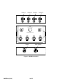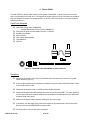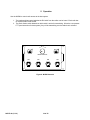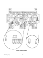
1
INSTALLATION AND OPERATION MANUAL Multiple-Radio Interface Module 41021G-01 19537P-26 (11-12) 2012 David Clark Company Incorporated Table of Contents Cautions and Warnings .......................................................................................................... 1 Parts/Tools List ....................................................................................................................... 2 Supplied by David Clark ...................................................................................................... 2 Customer Supplied .............................................................................................................. 2 System Overview .................................................................................................................... 3 1. Surface Mounting the M-RIM ............................................................................................. 5 Parts/Tools Required ........................................................................................................ 5 Procedure ......................................................................................................................... 5 Location Considerations ................................................................................................... 5 Mounting .......................................................................................................................... 5 2. Radio Cables ................................................................................................................... 10 Parts/Tools Required ...................................................................................................... 10 Procedure ....................................................................................................................... 10 3. System Interface Cable ................................................................................................... 11 Parts/Tools Required ...................................................................................................... 11 Procedure ....................................................................................................................... 11 4. Power Cable...................................................................................................................... 12 Parts/Tools Required ...................................................................................................... 12 Procedure ....................................................................................................................... 12 5. Operation .......................................................................................................................... 14 6. Testing & Troubleshooting .............................................................................................. 15 Parts/Tools Required ...................................................................................................... 15 Test Procedure ............................................................................................................... 15 Troubleshooting .............................................................................................................. 15 Appendix A ...........................................................................................................................A-1 P/N 40688G-47 Waterproof Fuse Kit .............................................................................A-1 Installation Instructions ..................................................................................................A-1 Parts/Tools Required .....................................................................................................A-1 Procedure ......................................................................................................................A-1 Appendix B ...........................................................................................................................B-1 M-RIM Adjustments .......................................................................................................B-1 Transmit Audio Level Adjustments ................................................................................B-1 Receive Audio Level Adjustments .................................................................................B-1 Appendix C .......................................................................................................................... C-1 Specifications ............................................................................................................... C-1 19537P-26 (11-12) i Cautions and Warnings READ AND SAVE THESE INSTRUCTIONS. Follow the instructions in this installation manual. These instructions must be followed to avoid damage to this product and associated equipment. Product operation and reliability depends on proper installation. DO NOT INSTALL ANY DAVID CLARK COMPANY PRODUCT THAT APPEARS DAMAGED. Upon unpacking your David Clark product, inspect the contents for shipping damage. If damage is apparent, immediately file a claim with the carrier and notify your David Clark product supplier. ELECTRICAL HAZARD - Disconnect electrical power when making any internal adjustments or repairs. All repairs should be performed by a representative or authorized agent of the David Clark Company. STATIC HAZARD - Static electricity can damage components. Therefore, be sure to ground yourself before opening or installing components. 19537P-26 (11-12) 1 of 15 Parts/Tools List Supplied by David Clark Multiple-Radio Interface Module M9840FM SOLO Flush Mount Kit C98-20PW Cable Assy, Power System Interface Cable C98-20RD* Radio Cables Headset Station Mounting Kit (P/N 41021G-01) (P/N 40688G-70) (P/N 40892G-02) (P/N system dependent) (P/N 40892G-01) (P/N 40688G-62) *Other versions available. Contact factory with radio make and model. Customer Supplied Screwdriver selection Pen/Pencil Drill 3/16” drill bit 11/32” nut driver or wrench Wire strippers Wire cutters Wire terminals Wire tie assortment Tape Measure Soldering Iron/Solder Radio adapters (for interfacing to radios—supplied by radio manufacturer) Pin assignments for each radio adapter (supplied by radio manufacturer) 19537P-26 (11-12) 2 of 15 System Overview The Multiple-Radio Interface Module (M-RIM) is a weather-resistant radio interface designed for the marine environment. It is a companion product to the David Clark Series 3800, 9500, 9800, and Solo product lines, intended to increase the number of radios connected to the host system. The M-RIM allows up to four mobile radios to be connected to one radio port on the host system. Primary components of the system are indicated in Table 1. In addition, a basic layout of the system is shown in Figure 1. Component Part and Model Numbers Multiple-Radio Interface Module Multiple-Radio Interface Module - Part Number 41021G-01 Flush Mounting SOLO Flush Mount Kit – Model Number M9840FM (optional accessory) Cables Power Cable – Model Number C98-20PW (one required) System Interface Requirements: Series 9800 and SOLO Interface: - C98-20MR1 cable (P/N: 40892G-13, qty. 1 each) Series 3800 Interface: - C98-20RD cable (P/N: 40892G-01, qty. 1 each) - 6 pin MS connector kit (P/N: 18352G-05, qty. 1 each) Series 9500 Interface: - C98-20RD cable (P/N: 40892G-01, qty. 1 each) Radio Cables – Model Number C98-20RD* (1 per Radio Input, maximum of 4) *Other versions available. Contact factory with radio make and model. Table 1: System Components 19537P-26 (11-12) 3 of 15 Radio B Radio A C98-20RD* C98-20RD* C98-20RD* A Radio D Radio C B C C98-20RD* D R R RADIO SELECT ON ON ON ON RX A RX B RX C RX D C98-20PW C98-20MR* To Power Source To Host System Figure 1: Typical Layout 19537P-26 (11-12) 4 of 15 1. Surface Mounting the M-RIM Parts/Tools Required Multiple-Radio Interface Module (41021G-01) Pencil/Pen Drill 3/16” Drill Bit Drilling Template (Figure 3) Philips-head screwdriver Flat-head screwdriver 11/32-inch nut driver or wrench Procedure Location Considerations Select a location on a flat surface that is out-of-the-way, and provides adequate room to attach all cables. Be sure to allow for internal access, as adjustments may be necessary. The M-RIM is weather resistant, however the mounting location should be chosen to minimize direct exposure to the elements. Mounting Using a Philips screwdriver, remove the 4 screws on the cover of the M-RIM and lift off the cover. Observe the 4 mounting holes in each corner, as shown in Figure 2. Position the M-RIM Drilling Template and mark each hole with a pencil. Confirm the location and carefully drill each hole using the drill and 3/16” bit. Position the M-RIM and insert a 3/16” machine screw into each mounting hole. On the backside of the mounting wall, use the provided flat washer and lock nut to secure the M-RIM (Figure 2). 19537P-26 (11-12) 5 of 15 NYLON WASHER STAINLESS STEEL SCREW HEADSET STATION CUSTOMER PANEL 7/8” MAX. DIMENSION STAINLESS STEEL WASHER STAINLESS STEEL NUT Figure 2: M-RIM Mounting Diagram 19537P-26 (11-12) 6 of 15 Figure 3: M-RIM Mounting Template 19537P-26 (11-12) 7 of 15 This page intentionally left blank 19537P-26 (11-12) 8 of 15 Radio A Radio B A B C Radio C Radio D D R R RADIO SELECT ON ON ON ON RX A RX B RX C RX D Power Host System Figure 4: M-RIM Connections 19537P-26 (11-12) 9 of 15 2. Radio Cables The C98-20RD Radio Cable is used to interface a marine or mobile radio to the M-RIM. One end of the cable connects to the M-RIM and the other end connects to the radio. Since the interface is different for each type of radio, the C98-20RD is left un-prepared at the radio end so that the installer may choose the correct interface. Note: This procedure applies only to the C98-20RD Radio Cable. Contact factory if assistance with other cables is needed. Parts/Tools Required C98-20RD Radio Cable (One for each radio to be interfaced) Radio adapters (for interfacing to radios—supplied by radio manufacturer) Pin assignments for each radio adapter (supplied by radio manufacturer) Wire Crimping/Cutting/Soldering/etc tools (depends on radio interface) Wire ties Figure 5: C98-20RD Radio Cable Procedure Determine the path of the cable between each radio and the M-RIM. The radios should already be installed and tested. The cable should be routed using under-deck conduits and be as far as possible from radio antenna coax cables and anywhere water may collect. Measure the length of cable necessary. Add 3 feet for a service loop and trim. Route the cable. The connector end connects to the M-RIM. Leave enough excess cable at the radio end for preparation of radio interface. Determine which radio letter this radio is (i.e., Radio A, B, C, or D) and connect Radio Cable to the M-RIM. See Figures 1&4 for connector locations. To connect the cable to the M-RIM, align keyways and push. Then push and turn collar clockwise until it stops. Pull back gently on the cable to ensure connector is properly locked. Prepare the radio interface in accordance with manufacturer’s instructions. See Table 2 for C98-20RD Radio Cable wire color functions. Repeat this procedure for remaining radios. Color Red White Orange Brown Green Black Shield Function Mic Hi (+) Mic Lo (-) PTT Hi (+) PTT Lo (-) Ear Hi (+) Ear Lo (-) Shield (To PTT Lo or Mic Lo) Table 2: Radio Cable Wire Color Functions 19537P-26 (11-12) 10 of 15 3. System Interface Cable The C98-20MR* Cables are used to interface the M-RIM to a radio port on David Clark Company Inc. Series 3800, 4200, 9500, or 9800 intercom systems. One end of the cable connects to the M-RIM and the other end connects to the intercom system. Parts/Tools Required System Interface Requirements: Series 9800 and SOLO Interface: o C98-20MR1 cable (P/N: 40892G-13, qty. 1 each) Series 3800 Interface: o C98-20RD cable (P/N: 40892G-01, qty. 1 each) o 6 pin MS connector kit (P/N: 18352G-05, qty. 1 each) Series 9500 Interface: o C98-20RD cable (P/N: 40892G-01, qty. 1 each) Wire ties Procedure Determine the path of the cable between the host system and the M-RIM. The host system should already be installed and tested. The cable should be routed using under-deck conduits and be as far as possible from radio antenna coax cables and anywhere water may collect. Route the cable and connect to the M-RIM. See Figures 1&4 for connector location. To connect the cable to the M-RIM, align keyways and push. Then push and turn collar clockwise until it stops. Pull back gently on the cable to ensure connector is properly locked. Connect the other end of the interface cable to the host system. Refer to the host system installation/operation manual for further instructions. 19537P-26 (11-12) 11 of 15 4. Power Cable The C98-20PW is a 20-foot cable used to provide power to the M-RIM. It has a connector on one end and is unterminated on the other end. It is important to choose a power “pick-off” point that can provide at least two amperes of current at a voltage between 11-30VDC. Direct connection to a 2-Amp fuse/circuitbreaker is preferred. Parts/Tools Required C98-20PW Power Cable (40892G-02) o Includes David Clark 2-Amp Fuse kit (40688G-47) Power pick-off point (circuit breaker/Fuse box, 11-30VDC) Soldering iron/Solder Wire terminals Wire cutters/ Wire strippers Tape Measure Wire ties Figure 6: C98-20PW Cable with 40688G-47 2-Amp Fuse kit Procedure Determine the location of a 2-Amp circuit breaker to be used and how to connect to it (solder, screw terminals, lugs, etc). If only a higher-amperage circuit breaker is available, it may be used, but the David Clark 2-Amp Fuse Kit must also be used. Determine the location of the 11-30VDC and Ground pick-off points. Determine the path of the cable between the power source and the M-RIM. The cable should be routed using under-deck conduits and be as far as possible from radio antenna coax cables and anywhere water may collect. Measure the length of cable necessary, adding 3 ft as a service loop. If necessary, trim the length of the cable to the length you just determined in the previous step. Be sure to trim the UN-PREPARED end of the cable. Route the cable. Use wire ties where necessary. 19537P-26 (11-12) 12 of 15 Connect the cable to the jack on the M-RIM labeled “Power”, see Figures 1&4. To connect the cable to the M-RIM, align keyways and push. Then push and turn collar clockwise until it locks into place. Pull back gently on the cable to ensure connector is properly locked. Before continuing, ensure that power is shut off to the point where you are going to connect the power cable! Using the wire cutters and wire strippers, prepare the end of the cable as necessary for your installation (Figure 7). If using the David Clark 2-Amp Fuse Kit, please see Appendix A for assembly instructions. Connect the cable to the power source o o Connect the RED to the positive (+) terminal. Connect the BLACK and SHIELD to the negative (-) terminal. Do not turn on power at this time, wait until Section 6. Testing & Troubleshooting. RED BLACK/SHIELD Figure 7: C98-20PW Power Cable 19537P-26 (11-12) 13 of 15 To 2 amp circuit breaker/fuse 5. Operation Use the M-RIM to control radio access to the host system. 1. The toggle switches control whether the RX audio from the radios can be heard. Each radio has its own RX Audio On/Off switch. 2. The Radio Select switch determines which radio is active for transmitting. When the user presses PTT (see instructions for host system), they will be transmitting over the radio that is selected. A B C D R R RADIO SELECT ON ON ON ON RX A RX B RX C RX D Figure 8: M-RIM Controls 19537P-26 (11-12) 14 of 15 6. Testing & Troubleshooting Parts/Tools Required Completion of the previous installation sections (1-4) in their entirety Read section 5, Operation An assistant (optional) Test Procedure Double-Check all connections and wiring from the previous sections. Complete connections of power cables to power source. Turn on power at the pick-off point/source. Verify that receive audio from all radios is heard (see host system instructions). Verify transmit access to all radios. o o o Using a scanner or an assistant at another radio, verify that you can hear, key, and speak over the selected radio (see host system instructions). Verify TX audio level. If adjustment is necessary, refer to Appendix B for TX modulation adjustment. Repeat this procedure for the remaining radios. Troubleshooting Symptom Possible Cause(s) No (or low) radio receive audio 1. 2. 3. 4. 5. Power applied to M-RIM? Radio turned on? Radio’s volume setting up to an audible level (on radio)? Check radio settings/wiring. Check host system troubleshooting guide. No radio transmit 1. 2. 3. 4. Power applied to M-RIM? Radio turned on? Check radio settings/wiring. Check host system troubleshooting guide. Too low or too high radio transmit audio 1. See Appendix B for adjustment information. Table 3: Troubleshooting 19537P-26 (11-12) 15 of 15 Appendix A P/N 40688G-47 Waterproof Fuse Kit Installation Instructions Parts/Tools Required • • • • • 1/8-inch diameter heat shrink tubing Wire strippers Crimp tool (Radio Shack P/N 64-409 or equivalent) Crimp terminals 2-Amp fuse kit Procedure 1. Using a heat gun, install 1/8" diameter heat shrink tubing* over one end of the 4" red wire (supplied). Install the second piece of 1/8" diameter heat shrink tubing over the red wire on the C98-20PW Power Cable. 2. Thread red wire of power cord with heat shrink tubing* into one end of fuse holder. 3. Thread the heat shrink end of the 4-inch red wire into other end of fuse holder. 4. Strip insulation on both wires 1/4 inch. 5. Crimp fuse clips to both wires. (Recommended crimp tool Radio Shack No. 64-409 or equivalent). 6. Insert 2-amp fuse. 7. Snap two halves of housing together. * Note: The heat shrink tubing is necessary in order to provide weather tightness. Figure A1: Proper assembly of Fuse Holder Kit (40688G-47) 19537P-26 (11-12) A1 Appendix B M-RIM Adjustments Transmit Audio Level Adjustments Under most circumstances these adjustments have been pre-set to optimum levels and should never need to be performed in the field. However, they are included in this section should their adjustment be necessary. To increase or decrease the transmit mic audio level for each radio, remove the top cover and locate and adjust the appropriate potentiometer (See Figure B1 for the locations of these components): For Radio A, locate and adjust R8 For Radio B, locate and adjust R7 For Radio C, locate and adjust R6 For Radio D, locate and adjust R5 Turning the potentiometers clockwise will increase the levels and counter-clockwise will decrease the levels. Use a jeweler’s screwdriver to make these adjustments. Also it is important to not increase the levels so much as to over-modulate the radios. This is in violation of FCC regulations and will seriously degrade the quality of the transmissions. If you have the equipment to measure the modulation, 4-4.5 KHz is an optimum level. Receive Audio Level Adjustments The factory has pre-set the receive audio adjustment potentiometers to levels which should be acceptable in most applications. Should the need arise to change these settings, the installer may do so by the following procedure: To increase or decrease the receive audio level for each radio, remove the top cover and locate and adjust the appropriate potentiometer (See Figure B1 for the locations of these components): For Radio A, locate and adjust R83 For Radio B, locate and adjust R20 For Radio C, locate and adjust R18 For Radio D, locate and adjust R16 Turning the potentiometers clockwise will increase the levels and counter-clockwise will decrease the levels. Use a jeweler’s screwdriver to make these adjustments. 19537P-26 (11-12) B1 Figure B1: Adjustment Locations 19537P-26 (11-12) B2 Appendix C Specifications 1. Supply voltage: 11 VDC Minimum 30 VDC Maximum 2. Input current: 2 A Maximum (@ 12VDC) 1 A Typical (@ 12VDC) 3. RX audio input: 8.5 V RMS Maximum 4.25 V RMS Typical 4. TX audio output: 700 mV RMS Maximum 400 mV RMS Typical Table C1: Specifications 19537P-26 (11-12) C1