1
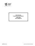
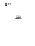
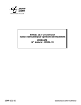
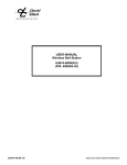
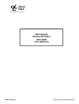
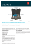
USER MANUAL Gateway Expansion Module U9925-GEM (P/N: 40995G-03) 19542P-91 (12-13) 2013 DAVID CLARK COMPANY INCORPORATED Cautions and Warnings READ AND SAVE THESE INSTRUCTIONS. Follow the instructions in this installation manual. These instructions must be followed to avoid damage to this product and associated equipment. Product operation and reliability depends on proper usage. DO NOT INSTALL ANY DAVID CLARK COMPANY PRODUCT THAT APPEARS DAMAGED. Upon unpacking your David Clark product, inspect the contents for shipping damage. If damage is apparent, immediately file a claim with the carrier and notify your David Clark product supplier. ELECTRICAL HAZARD - Disconnect electrical power when making any internal adjustments or repairs. All repairs should be performed by a representative or authorized agent of the David Clark Company. STATIC HAZARD - Static electricity can damage components. Therefore, be sure to ground yourself before opening or installing components. 19542P-91 (12-13) 1 of 5 Overview The U9925-GEM (40995G-03) Gateway Expansion Module is a fixed-mounted device that allows two, three, or four gateways to be connected together, creating a wireless-only intercom of up to 16-users. Compatible gateways include U9922-G38 (40995G-01) and its EU equivalent. Figure 1: Overview of Gateway Expansion Module 19542P-91 (12-13) 2 of 5 Installation Power The U9925-GEM is powered using the C98-20PW 20-foot power cable. This cable may be cut to the required length. Connect the flying leads RED (+) and Black (-) to an 8-32VDC power source, fused at 2A. Attach the molded connector end of the cable to the POWER input on the U9925GEM. RED To 2 amp circuit breaker/fuse BLACK/SHIELD Figure 2: C98-20PW Power Cable The C98-20PW is supplied with a fuse kit which may be used if a 2A fused power source is not available. See Figure 3 below for assembly details. Figure 3: Fuse Kit Assembly 19542P-91 (12-13) 3 of 5 Gateway Connection Connect up to four wireless gateways to the SYSTEM ports on the U9925-GEM using the model C99-20MS Interface Cable (P/N: 40935G-05). To connect the cable to the U9925-GEM: 1. Align keyways on the connectors and push 2. Firmly turn collar clockwise until it locks into place 3. Pull back gently on the cable to ensure connector is properly locked Operation The U9925-GEM Gateway Expansion Module does not have a user interface and does not require configuration. Once installed and power is applied all connected gateways will function as if they were connected to an intercom. Communication between wireless users connected to all gateways is now possible. Up to 16 users can communicate with one U9925-GEM. Refer to the appropriate wireless gateway instruction manual for additional information. Note: When the Expansion Module is used with multiple U9922-G38 gateways, a C3821 Radio Interface Cable (P/N 18747G-06) must be connected to each gateway requiring radio transmit/receive capability. Any radio connected to one Gateway will be monitored by all users within the U9925-GEM system regardless of the Gateway to which they are connected. However, radio transmit will only be provided to those users linked to a Gateway which is in turn connected to the radio via a C3821 cable. For ease of radio install, multiple C3821 cables may be wired to individual MS connectors (P/N 18352G-17) and collected through a U3805 Radio Junction Module (P/N 41035G-01), which can then route a single C3821 directly to the radio. See C3821 Installation/Operation Instructions (doc. # 19510P-87.) 19542P-91 (12-13) 4 of 5 Care and Maintenance If necessary, the U9925-GEM may be wiped down with a mild soap and water mixture. Avoid storage of this product in direct sunlight or high temperature environments. The U9925-GEM is not user serviceable. Do not attempt to open the enclosure. If this product requires service, please contact the David Clark Customer Service department: Phone: 800.298.6235 E-Mail: [email protected] By Mail: Customer Service David Clark Company 360 Franklin Street Worcester, MA 01604 Specifications Operating Temperature Storage Temperature Power Requirements 19542P-91 (12-13) -14°F to 131°F (-10°C to +55°C) -4°F to 140°F (-20°C to +60°C) 8 to 32 VDC 5 of 5