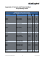
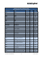
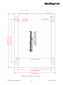
1
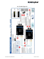
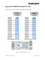
® Camera Fiber-Link Digital Camera Extension System For models CFL-3000, CFL-4000, CFL-5000 and CFL-6000 ® Extend Distribute Innovate Thinklogical, LLC® 100 Washington Street Milford, Connecticut 06460 U.S.A. Telephone: 1-203-647-8700 Fax: 1-203-783-9949 www.thinklogical.com Copyright Notice Copyright © 2012. All rights reserved. Printed in the U.S.A. Thinklogical, LLC ® 100 Washington Street Milford, Connecticut 06460 U.S.A. Telephone: 1-203-647-8700 All trademarks and service marks are the property of their respective owners. ® Extend Distribute Innovate Subject: Camera Fiber-Link Video Extension System - CFL3000, -4000, -5000, -6000 Revision: E, June 2012 Camera Fiber-Link Extender Manual, Rev. E, June, 2012 Page | i ® Extend Distribute Innovate Table of Contents 1. Introduction 1.1 The Logical Solution 1.2 The Camera Fiber-Link System 1.2.1. Thinklogical® Camera Fiber-Link Models 1.2.2. Increased Security 1.2.3. Class 1 LASERs 1 1 1 3 4 4 2. System Features 2.1. General System Features 2.2. Hardware Features 2.2.1. CFL-3000 2.2.2. CFL-4000 2.2.3. CFL-5000 2.2.4. CFL-6000 2.2.5. Power Enhancement Kit (Optional) 2.2.6. DIN Rails (Optional) 2.3. Technical Specifications 5 5 6 6 7 8 9 9 9 10 3. Connecting the Camera Fiber-Link 3.1 Types of Connections 3.1.1. Fiber Cable 3.1.2. Digital Video Camera Side 3.1.3. Digital Video Frame Grabber Side 3.1.4 Serial Port 3.1.5 Camera Control 3.2. AC Power 3.2.1. Standard Version: 5V-12V 3.2.2. Industrial Version: 12V-24V 12 12 12 12 12 12 14 14 14 15 4. Order of Installation Events 4.1 CFL-3000 4.2 CFL-4000 4.3 CFL-5000 4.4 CFL-6000 15 16 17 18 19 5. Regulatory & Safety Compliance 5.1 Safety Requirements 5.1.1. Symbols Found On Our Products 5.1.2. Product Serial Number 5.1.3. Connection to the Product 5.2 Regulatory Compliance 5.2.1. North America 5.2.2. Australia & New Zealand 5.2.3. European Union 5.2.3.1. Declaration of Conformity 5.2.3.2. Standards With Which Our Products Comply 5.3 Supplementary Information 20 20 20 20 20 20 20 20 21 21 21 21 Camera Fiber-Link Extender Manual ii Rev. E, June 2012 ® Extend 6. How to Contact Us 6.1 Customer Support 6.1.1 Website 6.1.2 Email 6.1.3 Telephone 6.1.4 Fax 6.2 Product Support 6.2.1 Warranty 6.2.2 Return Authorization 6.2.3 Our Address 22 22 22 23 23 23 24 24 24 24 Table 1 Available Models Table 2 Technical Specifications 3 10 Figure 1 Figure 2 Figure 3 Figure 4 Figure 5 2 6 7 8 9 Camera Fiber-Link and Cabling Application Drawing Top & side views of CFL-3000 Top & side views of CFL-4000 Top & side views of CFL-5000 Top & side views of CFL-6000 Figure 6 Serial Port (RJ45) Connections Figure 7 5V-12V Power Supply Figure 8 12V-24V Power Supply Figure 9 CFL-3000 Quick Start Diagram Figure 10 CFL-4000 Quick Start Diagram 13 14 15 16 17 Figure 11 CFL-5000 Quick Start Diagram Figure 12 CFL-6000 Quick Start Diagram Figure 13 DB9/RJ45 Adapter Pin-outs Figure 14 CFL Mounting Template 18 19 32 35 Appendix A Appendix B Appendix C Appendix D . 26 32 33 34 Camera and Frame Grabber Compatibility Chart DB9/RJ45 Adapter Pin-outs Maximum Distances for Fiber Types Camera Fiber-Link Mounting Template Camera Fiber-Link Extender Manual iii Distribute Innovate Rev. E, June 2012 ® Extend Distribute Innovate 1. Introduction 1.1. The Logical Solution Process and machine monitoring, safety, security and surveillance applications often require that remote cameras be positioned far from their controlling computers. Long distance image transmission, security and resolution are top priorities in these and many other environments. That’s why we’ve developed the Thinklogical® Camera Fiber-Link Extension System with the Camera-Link® standard for high performance digital cameras and frame grabbers. 1.2. The Camera Fiber-Link System The Camera Fiber-Link System uses a Camera Side Unit and a Frame Grabber Side Unit that are connected by duplex, multi-mode fiber optic cables, allowing Camera Link video support up to 350 meters (1150 feet) from the host computer with no loss of signal or resolution and without the use of amplifiers or repeaters of any kind. With industrial enhancements such as a threaded screwlock input for standard 5V-12V input power, or for our 12V-24V input power, designed for rugged industrial environments, the Camera Fiber-Link System is ideal for any application. CAMERA ® Conventions Used In This Manual As you read this manual you will notice certain conventions that bring your attention to important information. These are Notes and Warnings. Examples are shown below. Note: Important Notes appear in blue text preceded by a yellow exclamation point symbol, like this. A note is meant to call the reader’s attention to helpful information at a point in the text that is relevant to the subject being discussed. Warning! Warnings appear in red text, followed by blue text, and preceded by a red stop sign, like this. A warning is meant to call the reader’s attention to critical information at a point in the text that is relevant to the subject being discussed. BEFORE STARTING ANY PROCEDURE, IT IS RECOMMENDED THAT YOU READ THE INSTRUCTIONS THOROUGHLY! Camera Fiber-Link Extender Manual 1 Rev. E, June 2012 ® Extend Distribute Innovate CABLING: 50/125 um or 62.5/125 um, LC, SC or ST-type connector CBL-000001-002M (CAT5) CBL-000007-002M (MDR-26 M to M) PWR-000022-R (AC to DC Converter-Standard +5VDC) Figure 1: Thinklogical® Camera Fiber-Link-4000 Cabling Application Drawing The Camera Fiber-Link System from Thinklogical® allows the placement of a digital camera up to 350 meters (1150 feet) from the controlling computer without loss of resolution. Traditional copper cables are typically limited to 10 meters (32.81 feet) or less in such applications. Each Base or Medium/Full Camera Fiber-Link System includes a transmitter and receiver chassis connected by multi-mode fiber optic cables at ports L1 and L2.* The Medium/Full System requires a third, multi-mode fiber optic cable at port L3. The Frame Grabber unit connects directly to the computer and the Camera unit connects directly to the digital camera, each with a 2 meter Camera Link MDR-26 male-to-male cable (both included). Note: 350 meters (1150 feet) is the standard maximum distance for a continuous 50/125, 1000 MHz-km fiber. See Appendix D (pg. 34) for the maximum allowable distances of other fiber types. *The multi-mode fibers used with the CFL-4000 must be of equal length. Camera Fiber-Link Extender Manual 2 Rev. E, June 2012 ® Extend Distribute Innovate 1.2.1. Thinklogical® Camera Fiber-Link Models Part Number Description CFL-3000 CFL-000S03-SCRX CFL-000S03-SCTX VOP-S05 CFL-000M03-LCRX CFL-000M03-LCTX CFL-000M03-SCRX CFL-000M03-SCTX CFL-000M03-STRX CFL-000M03-STTX VOP-M04 VOP-M01 Camera Fiberlink 3000, Frame Grabber, Single Mode, SC/APC Camera Fiberlink 3000, Camera, Single Mode, SC/APC Camera Fiberlink 3000 Optics Option for TX or RX, Single Mode, Dual Fiber, 40km Camera Fiberlink 3000, Base Frame Grabber Side, Multi-Mode, LC Camera Fiberlink 3000, Base Camera Side, Multi-Mode, LC Camera Fiberlink 3000, Base Frame Grabber Side, Multi-Mode, SC Camera Fiberlink 3000, Base Camera Side, Multi-Mode, SC Camera Fiberlink 3000, Base Frame Grabber Side, Multi-Mode, ST Camera Fiberlink 3000, Base Camera Side, Multi-Mode, ST Camera Fiberlink 3000 Optics Option for TX or RX, Multi-Mode, Dual Fiber, 50M, 350M or 1000M, LC Camera Fiberlink 3000 Optics Option for TX or RX, Multi-Mode, Dual Fiber, 50M, 350M or 1000M, SC or ST CFL-4000 CFL-000S04-SCRX CFL-000S04-SCTX VOP-S05 CFL-000M04-LCRX CFL-000M04-LCTX CFL-000M04-SCRX CFL-000M04-SCTX CFL-000M04-STRX CFL-000M04-STTX VOP-M05 VOP-M02 Camera Fiberlink 4000, Full Frame Grabber, Single Mode, SC/APC Camera Fiberlink 4000, Full Frame Grabber, Single Mode, SC/APC Camera Fiberlink 4000 Optics Option for TX or RX, Single Mode,3 Fibers, 40km Camera Fiberlink 4000, Full Frame Grabber Side, Multi-Mode, LC Camera Fiberlink 4000, Full Camera Side, Multi-Mode, LC Camera Fiberlink 4000, Full Frame Grabber Side, Multi-Mode, SC Camera Fiberlink 4000, Full Camera Side, Multi-Mode, SC Camera Fiberlink 4000, Full Frame Grabber Side, Multi-Mode, ST Camera Fiberlink 4000, Full Camera Side, Multi-Mode, ST Camera Fiberlink 4000 Optics Option for TX or RX, Multi-Mode, 3 Fibers, 50M, 350M or 1000M, LC Camera Fiberlink 4000 Optics Option for TX or RX, Multi-Mode, 3 Fibers, 50M, 350M or 1000M, SC or ST CFL-5000 CFL-000S05-SCRX CFL-000S05-SCTX VOP-S08 CFL-000M05-LCRX CFL-000M05-LCTX CFL-000M05-SCRX CFL-000M05-SCTX CFL-000M05-STRX CFL-000M05-STTX VOP-M05 VOP-M02 Camera Fiberlink 5000, Industrial Frame Grabber, Single Mode, SC/APC Camera Fiberlink 5000, Industrial Frame Grabber, Single Mode, SC/APC Camera Fiberlink 4000 Optics Option for RX, Single Mode, 3 Fibers, 40km Camera Fiberlink 5000, Industrial Dual Base Frame Grabber Side, Multi-Mode, LC Camera Fiberlink 5000, Industrial Dual Base Camera Side, Multi-Mode, LC Camera Fiberlink 5000, Industrial Dual Base Frame Grabber Side, Multi-Mode, SC Camera Fiberlink 5000, Industrial Dual Base Camera Side, Multi-Mode, SC Camera Fiberlink 5000, Industrial Dual Base Frame Grabber Side, Multi-Mode, ST Camera Fiberlink 5000, Industrial Dual Base Camera Side, Multi-Mode, ST Camera Fiberlink 5000 Optics Option for TX or RX, Multi-Mode, 3 Fibers, 50M, 350M or 1000M, LC Camera Fiberlink 5000 Optics Option for TX or RX, Multi-Mode, 3 Fibers, 50M, 350M or 1000M, SC or ST Camera Fiber-Link Extender Manual 3 Rev. E, June 2012 ® Extend Distribute Innovate CFL-6000 CFL-000S06-SCRX VOP-S15 CFL-000M06-LCRX CFL-000M06-SCRX CFL-000M06-STRX VOP-S17 VOP-S16 Camera Fiberlink 6000, High Speed Dual Base Frame Grabber, Single Mode, SC/APC Camera Fiberlink 4000 Optics Option for TX or RX, Single Mode, 4 Fibers, 40km Camera Fiberlink 6000, High Speed Dual Base Frame Grabber Side, Multi-Mode, LC Camera Fiberlink 5000, High Speed Dual Base Frame Grabber Side, Multi-Mode, SC Camera Fiberlink 5000, High Speed Dual Base Frame Grabber Side, Multi-Mode, ST Camera Fiberlink 6000 Optics Option for TX or RX, Multi-Mode, 4 Fibers, 50M, 350M or 1000M, LC Camera Fiberlink 6000 Optics Option for TX or RX, Multi-Mode, 4 Fibers, 50M, 350M or 1000M, SC or ST Table 1: Available Models To complement its line of Camera Fiber-Link extenders, Thinklogical® also offers high performance USB 2.0 and Firewire 800 Camera Extenders. To contact a Thinklogical® sales representative for details, see the “How to Contact Us” section of this manual (pg. 22). 1.2.2. Increased Security Thinklogical’s® Camera Fiber-Link Systems are designed for high-resolution camera extension applications. The ability to position the cameras far from the CPU allows better control and security for your source equipment, which is especially important in applications where the cameras must be located in harsh, industrial or non-secured environments. Remote Mounting Each Camera Fiber-Link module can be used as a desk top or wall-mounted device. Mounting centers are provided with keyhole slots. (For vertical wall-mounting, it is recommended that you orient the unit with the fiber cables and power connector at the top and MDR-26 and RJ45 connectors at the bottom.) A mounting template is provided in Appendix D (pg. 34) for your convenience. 1.2.3. Class 1 LASERs The Camera Fiber-Link system is designed and identified as a Class 1 LASER product. CLASS 1 LASERS do not require any special precautions under conditions of normal use. Camera Fiber-Link Extender Manual 4 Rev. E, June 2012 ® Extend Distribute Innovate 2. Product Features 2.1 System Features Each Camera Fiber-Link System includes the following features: Supports all Camera-Link base (to full) configurations with pixel clocks 20-85 MHz Supports 1 dual-base or 2 individual-base cameras (CFL-5000 and CFL-6000) Fiber Count: CFL-3000 – 2 fibers CFL-4000 – 3 fibers CFL-5000 – 3 fibers CFL-6000 – 4 fibers Extend camera signals up to 350 meters (1150 feet) using standard multi-mode fiber Transparent Camera-Link® operation Compact design: Units are self-contained and do not require user adjustments HOUSING DIMENSIONS: 8.875” long x 5.44” wide x 1.19” high (225.425 mm x 138.13 mm x 30.16 mm high) Signal transmission via fiber optic cable – no RF interference Serial Port (RJ45) with RS-232 Interface Class 1 laser product Screw lock (threaded) power connector Chassis ground post Compatible with user’s own DC input Customer supplied power 5V-12V Power Enhancement Kit (optional) Customer supplied power 12V-24V Industrial Enhancement Kit (optional) DIN rail connectors for mounting Indicator LEDs The Green LED near the power connector is lit when appropriate power is connected to the power in port. The Red LED is lit solid (near the camera link connectors) when there is a loss of signal on the fiber. The Red LED blinks if the fiber is installed properly but there is no clock from the camera present. The Red LED is OFF when the unit is receiving appropriate signals. Camera Fiber-Link Extender Manual 5 Rev. E, June 2012 ® Extend Distribute Innovate 2.2. Hardware Features 2.2.1. CFL-3000 Distribute Innovate ® CAMERA FIBER-LINK® FRAME GRABBER Extend SERIAL The CFL-3000 Extender supports camera signals and serial connections (both the SerTFG and SerTC within the MDR cable, and three pairs of RS-232 lines). The CFL-3000 supports Base configurations and requires two fibers. Each unit is housed in a compact, metal enclosure (7.00” x 5.44” x 1.19”). The CFL-3000 is available with SC-, ST- or LC-type fiber optic connectors. Digital Camera Extension System CFL- 3000 HI-SPEED BASE FRAME GRABBER SIDE L2◄ Distribute Innovate CAMERA SERIAL Extend Powered by MRTS Technology ® CAMERA FIBER-LINK® CAMERA L1► Digital Camera Extension System CFL- 3000 HI-SPEED BASE CAMERA SIDE L1◄ L2► Powered by MRTS Technology CAMERA Figure 2: CFL-3000 Camera Side (CFL-000M03-SCTX) and Frame Grabber Side (CFL-000M03-SCRX) Camera Fiber-Link Extender Manual 6 Rev. E, June 2012 ® Extend Distribute Innovate 2.2.2. CFL-4000 Distribute Innovate ® CAMERA FIBER-LINK® FRAME GRABBER BASE Extend SERI AL The CFL-4000 Extender supports camera signals and serial connections (both the SerTFG and SerTC within the MDR cable, and three pairs of RS-232 lines). The CFL-4000 supports Full/Medium/Base configurations and requires three fibers. Each unit is housed in a compact, metal chassis (7.00” x 5.44” x 1.19”). The CFL-4000 is available with SC-, ST- or LC-type fiber optic connectors. L3◄ HI-SPEED BASE /MEDIUM/FULL FRAME GRABBER SIDE L2► L1► C A MER A Distribute Innovate SERI AL Powered by MRTS Technology ® CAMERA FIBER-LINK® CAMERA BASE Extend FRAME GRABBER MEDIUM/FULL Digital Camera Extension System CFL- 4000 L3► HI-SPEED BASE /MEDIUM/FULL CAMERA SIDE L1◄ L2◄ CA MERA CAMERA MEDIUM/FULL Digital Camera Extension System CFL- 4000 Powered by MRTS Technology Figure 3: CFL-4000 Camera Side (CFL-000M04-SCTX) and Frame Grabber Side (CFL-000M04-SCRX) Camera Fiber-Link Extender Manual 7 Rev. E, June 2012 ® Extend Distribute Innovate 2.2.3 CFL-5000 CAMERA FIBER-LINK ® Digital Camera Extension System CFL- 5000 L3◄ HI-SPEED DUAL BASE FRAME GRABBER SIDE L2► Extend Distribute Innovate C A MERA SERI AL Powered by MRTS Technology L1► ® CAMERA FIBER-LINK® Digital Camera Extension System CFL- 5000 L3► HI-SPEED DUAL BASE CAMERA SIDE L1◄ CA MERA L2◄ FRAME GRABBER BASE 1 ® FRAME GRABBER BASE 2 Innovate CAMERA 1 Distribute CAMERA 2 Extend SERI AL The CFL-5000 Extender supports camera signals and serial connections (both the SerTFG and SerTC within the MDR cable, and three pairs of RS-232 lines). The CFL-5000 supports one or two base Camera-Link cameras or one dual-base Camera-Link camera configurations. Each unit is housed in a compact, metal enclosure (7.00” x 5.44” x 1.19”). The CFL-5000 is available with SC(standard), ST- or LC-type fiber optic connectors. Powered by MRTS Technology Figure 4: CFL-5000 Camera Side (CFL-000M05-SCTX) and Frame Grabber Side (CFL-000M05-SCRX) Each CFL-5000 configuration requires three fibers. The Camera Side Unit receives data from each camera and converts the data into optical signals. These signals are sent to the CFL-5000 Frame Grabber Side Unit, which in turn converts the optical signals into video data and sends them to the one dual-base frame grabber (CPU). Camera Fiber-Link Extender Manual 8 Rev. E, June 2012 ® Extend Distribute Innovate 2.2.4. CFL-6000 Distribute Innovate ® FRAME GRABBER BASE 1 Extend SERIAL The CFL-6000 Dual Camera Fiber-Link Receiver is a unique component designed for users who have two cameras in different locations and where space is a concern. The Dual CFL-6000 Frame Grabber receives optical data from two CFL-3000 Camera Side transmitters (over two optical fibers each) and converts them back into video data to send out to a frame grabber base (CPU). Each unit is housed in a compact, metal enclosure (7.00” x 5.44” x 1.19”). The CFL-6000 is available with SC- (standard), ST- or LC-type fiber optic connectors. CAMERA FIBER-LINK® Upper Connector L2 ◄ CAMERA 2 L1 ► Lower Connector L2 ◄ CAMERA 1 L1 ► FRAME GRABBER BASE 2 Digital Camera Extension System CFL- 6000 HI-SPEED DUAL BASE FRAME GRABBER SIDE CAMERA Powered by MRTS Technology ® Figure 5: CFL-6000 Frame Grabber Side (CFL-000M06-SCRX) 2.2.5. Power Enhancement Kit (Optional) The entire line of Thinklogical® Camera Fiber-Link Extenders features industrial enhancements, including a screw lock (threaded) input-power connector designed to meet the needs of a rugged industrial environment. The CFL-5000 and CFL-6000 models are available with input power ranges of 5-12V (standard) or 12-24V (industrial). Users can also choose to use their own DC input. A chassis ground post is included. 2.2.6 DIN Rails (Optional) Each unit features DIN rail connectors for easy mounting, making it is possible to position your cameras in any setting while keeping the computer in a secure location. (A mounting template is included in Appendix D, pg. 34 for your convenience.) Camera Fiber-Link Extender Manual 9 Rev. E, June 2012 ® Extend Distribute Innovate 2.3. Technical Specifications Each Thinklogical® Camera Fiber-Link System is designed to the following specifications: CFL-3000: (1) CBL000007-002MR MDR-26 male cable, 2 meters (1) KIT-000013 CAMERALINK W/RJ45 adapter/cable kit CFL-4000: (2) CBL000007-002MR MDR-26 male CABLE, 2 meters (1) KIT-000013 CAMERALINK W/RJ45 adapter/cable kit CFL-5000: (2) CBL000007-002MR MDR-26 male CABLE, 2 meters (1) KIT-000013 CAMERALINK W/RJ45 adapter/cable kit Electrical Cable (supplied with CFL-6000: (2) CBL000007-002MR MDR-26 male CABLE, 2 meters system) (1) KIT-000013 CAMERALINK W/RJ45 adapter/cable kit KIT-000013 contains the following: (1) ADP-000007 DB9M TO RJ45F Adapter (1) ADP-000008 DB9F TO RJ45F Adapter (2) CBL000001-002MR CAT5 cable assembly, 2 meters For Adapter Pin-outs, see Appendix B, pg. 32. Serial RJ45 (DB9M to RJ45 and DB9F to RJ45 adapters included) Protocol Camera Link compliant (supports base/medium/full configurations) Two LEDs on each Camera Fiber-Link module: Loss of Signal [LOS] (Red ON if no signal) Indicators (Red BLINKS if no camera is connected) (Red OFF for good connection) Power (Green ON when power is applied) Optical Cable Fiber Count: CFL-3000 (Base): 2 CFL-4000 (Full/Medium/Base): 3 CFL-5000 (Dual Base): 3 CFL-6000 (Dual Base RX): 4 Fiber Type: Multi-mode, 50/125um or 62.5/125um SC-type connectors Fiber Connector Type: SC Standard / ST or LC Optional Maximum Fiber Distance: See Appendix C, pg. 33 (Fiber Cable is either customer-supplied or ordered from Thinklogical) Camera Fiber-Link Extender Manual 10 Rev. E, June 2012 ® Extend Distribute Innovate LASER Output 850 nanometers Operating Temp 0 to 50°C (32 to 122°F), 5 to 95% RH, non-condensing and Humidity Pixel Clock 20 to 85 MHz Bit Assignments CFL-3000/CFL-5000/CFL-6000: Supports Base Configurations CFL-4000: Supports Full/Medium/Base Configurations CFL-3000: Camera Side -- (1) MDR-26 (supports Base only) Frame Grabber Side -- (1) MDR-26 (supports Base only) CFL-4000: Camera Side -- (2) MDR-26 (supports Full/Medium/Base) Frame Grabber Side -- (2) MDR-26 (supports Full/Medium/Base) Camera/Frame CFL-5000: Camera Side -- (2) MDR-26 (supports Base only) Grabber Connector Frame Grabber Side -- (2) MDR-26 (supports Base only) CFL-6000: Camera Side 1-- (1) MDR-26 (supports Base only) Camera Side 2 -- (1) MDR-26 (supports Base only) Frame Grabber Side -- (2) MDR-26 (supports Base only) Dimensions Weights CFL-3000, CFL-4000, CFL-5000 and CFL-6000: 7.0” x 5.44” x 1.19” (177.80 x 138.13mm x 30.23mm) Weight: 1 lb. per unit Shipping Weight: 6 lbs. Standard 5-12V: Supplied universal external power supply equipped with threaded screw lock connector for each side. Power Supply Industrial 12-24V: Supplied universal external power supply equipped with threaded screw lock connector for each side. Standard Version: Wall Mount (PWR-000022-R) Input 100-240VAC, 50-60Hz AC Adapter Industrial Version: Desktop (PWR-000033-R) Input 90-264VAC, 47-63Hz, DC Current AC Power Consumption Warranty Camera Side: 1.5A, steady state; 2.5A, peak Frame Grabber Side: 1.5A, steady state; 2.5A, peak Camera Side: Initial Power Draw: 10W Typical Input Power: 4.0W to 4.5W Frame Grabber Side: Initial Power Draw: 10W Typical Input Power: 3.75W to 4.5W 12 months from date of purchase. Extended warranties available at time of purchase. Table 2: Technical Specifications Camera Fiber-Link Extender Manual 11 Rev. E, June 2012 ® Extend 3. Distribute Innovate Connecting the Camera Fiber-Link 3.1 Types of Connections 3.1.1. Fiber Cable Either two (Base version) or three (Medium/Full version) fiber optic cables will connect the Frame Grabber Unit (near the CPU) and the Camera Side Unit (near the camera). The standard simplex and/or duplex, multi-mode fiber cables must be 50 or 62.5 micron, terminated with an SC-, ST- or LC-type connector and no longer than 1150 running feet (350 meters). A single-mode fiber version is also available that can extend up to 40 kilometers. Be careful to not kink or pinch the fiber cable as it is being installed and keep all bend radii to no less than 3 inches (76.2mm). Be sure to dress the cable to prevent it from being crushed, pinched or otherwise damaged. BEFORE STARTING ANY PROCEDURE, IT IS RECOMMENDED THAT YOU READ THE INSTRUCTIONS THOROUGHLY! Note: For CFL- 4000 and CFL- 5000 Units it is necessary that the multi-mode fiber on L1 and L2 to be of equal length. Note: The Camera Fiber-Link is available with SC-, ST- or LC-type fiber connectors upon request. Note: 350 meters (1150 feet) is the standard maximum distance for a continuous fiber type of 50/125, 1000MHz-km. See Appendix D (pg. 34) for maximum distances of other fiber types. 3.1.2. Digital Video Camera Side The Camera Side unit connects to your video camera using a supplied MDR-26 male-to-male cable (CBL-000007-002M). The Base version includes one cable and the Medium/Full version includes two. 3.1.3. Digital Video Frame Grabber Side The Frame Grabber Side unit connects to your controlling computer’s Frame Grabber with a supplied MDR-26 male-to-male cable (CBL-000007-002M). The Base version includes one cable and the Medium/Full version includes two. 3.1.4. Serial Port Both the Camera Side unit and the Frame Grabber Side unit have a serial port (RJ45 connector). This RS-232 interface connects to any external sensor, external lighting, etc., using Camera Fiber-Link Extender Manual 12 Rev. E, June 2012 ® Extend Distribute Innovate the supplied CAT5 Cable Assembly (CBL-000001-002M). A DB9M to RJ45F and a DB9F to RJ45F adapter is included with KIT-000033 (Fig. 6, pg. 13). The serial port on the CFL-6000 varies from the CFL-3000, CFL-4000, and CFL-5000 systems in that serial data from the PC is broadcast to both Camera Side units (transmitters). However, serial data to the PC only comes from Camera 1 on the Camera Side (transmitter 1). Serial Port communications are sampled at approximately 32 MHz going from the Camera to Frame Grabber (RX, DSR, CTS) Serial Port communications are sampled at 97 MHz going from the Frame grabber to the Camera (RTS, TX, DTX). The pin-outs for the Serial Port (RJ45 connector) are as follows: Figure 6: Diagram showing the serial connections used as data terminal connections and the included DB9 to RJ45 adapters. Other uses are also possible using each signal to control a function at the camera end, such as lighting, sensors, etc. Camera Fiber-Link Extender Manual 13 Rev. E, June 2012 ® Extend Distribute Innovate 3.1.5. Camera Control Communications from the Camera to the Frame Grabber, SerTFG—Differential pair with serial communications to the frame grabber, are sampled at 97 MHz. Communications from the Frame Grabber to the Camera, SerTC—Differential pair with serial communications to the camera, are Sampled at 97 MHz. Camera Controls 1-4 (CC1, CC2, CC3 and CC4) are sampled at 97 MHz. 3.2. AC Power 3.2.1. Standard Version: 5V-12V Separate wall-pack AC-to-DC converters (Part Number PWR-000022-R) are included. A power jack is provided on both units and accepts the +5VDC input. The green power LED will light when the unit is receiving power. The AC wall pack has a universal power rating (100-240 VAC, 50-60 Hz) and comes with slipon, interchangeable adapters for various AC power receptacles found throughout the world. Use the appropriate AC power wall plug adapter for your country/location. Figure 7: A 5V–12V Power Supply is provided with each Camera Fiber-Link unit. Each comes with three international AC power wall plug adapters. Camera Fiber-Link Extender Manual 14 Rev. E, June 2012 ® Extend Distribute Innovate 3.2.2 Industrial Version: 12V-24V For the Industrial Power Input Option, separate desktop AC-to-DC converters (Part Number PWR-000033-R) are included. A power jack is provided on both units and accepts the +12VDC input. The green power LED will light when the unit is receiving power. The AC desktop power pack has a universal power rating (90-264 VAC, 47-63 Hz) and is also supplied with a country-specific, industry standard AC Power Cord. A separate +5V (CON-000120-R) or +12V (CON-000119-R) threaded screw-lock connector is available for customers who prefer to use their own power source. Figure 8: Two 12V–24V Desktop Power Supplies are provided with each Industrial Version Camera Fiber-Link System. 4. Order of Installation Events The following pages contain Quick Start Guides for each of the four CFL models available from Thinklogical®. Each guide contains specific information about the contents of your Camera Fiber-Link System, as well as order of installation events and detailed connection instructions. BEFORE STARTING ANY PROCEDURE, IT IS RECOMMENDED THAT YOU READ THE INSTRUCTIONS THOROUGHLY! Camera Fiber-Link Extender Manual 15 Rev. E, June 2012 ® Extend Distribute Innovate 4.1. CFL-3000 (Figure 9) Camera Fiber-Link Extender Manual 16 Rev. E, June 2012 ® Extend Distribute Innovate 4.2. CFL-4000 (Figure 10) Camera Fiber-Link Extender Manual 17 Rev. E, June 2012 ® Extend Distribute Innovate 4.3 CFL-5000 (Figure 11) Camera Fiber-Link Extender Manual 18 Rev. E, June 2012 ® Extend Distribute Innovate 4.4. CFL-6000 (Figure 12) Camera Fiber-Link Extender Manual 19 Rev. E, June 2012 ® Extend Distribute Innovate 5. Regulatory & Safety Compliance 5.1. Safety Requirements 5.1.1. Symbols Found On Our Products Markings and labels on our products follow industry-standard conventions. Regulatory markings found on the products comply with accepted industry requirements. 5.1.2. Product Serial Number Camera Fiber-Link products have a unique serial number printed on a label on the bottom of the chassis. The serial number includes a manufacturer’s date-code. The format for the date-code is 2-digits each for the month, the day and the year, and two or three digits for a unique unit number. This serial number is also found on the original shipping carton. 5.1.3. Connection to the Product Connections and installation hardware for all of our products use industry-standard devices and methods wherever possible. All wiring connections to the customers’ equipment are designed to minimize proprietary or customized connectors or cabling. Power connections are made with regionally appropriate power cords and approved methods. 5.2 Regulatory Compliance Thinklogical® Camera Fiber-Link products are designed and made in the U.S.A. Camera FiberLink products have been tested by a nationally recognized testing laboratory and found to be compliant with the following standards (both domestic USA and many international locations). Warning! This is a Class 1 product. In a domestic environment this product may cause radio interference, in which case the user may be required to take corrective measures. 5.2.1. North America These products comply with the following standards: Safety UL60950:2000 CAN/CSA C22.2 No. 60950-00 LASER Safety CDRH 21CFR 1040.10 Class 1 LASER Product Electromagnetic Interference FCC CFR47, Part 15, Class 1 Industry Canada ICES-003 Issue 2, Revision 1 5.2.2. Australia & New Zealand This is a Class 1 product. In a domestic environment this product may cause radio interference, in which case the user may be required to take corrective measures. Camera Fiber-Link Extender Manual 20 Rev. E, June 2012 ® Extend 5.2.3. Distribute Innovate European Union 5.2.3.1.Declaration of Conformity Manufacturer’s Name & Address: Thinklogical, LLC® 100 Washington Street Milford, Connecticut 06460 USA Telephone (203) 647-8700 Product Name: Camera Fiber-Link Video Extension System These products comply with the requirements of the Low Voltage Directive 72/23/EEC and the EMC Directive 89/336/EEC. 5.2.3.2.Standards with Which Our Products Comply Safety IEC60950:1992+A1, A2, A3, A4, A11 LASER Safety IEC60825:2001 Parts 1 and 2 Class 1 LASER Product Electromagnetic Emissions EN55022: 1994 (IEC/CSPIR22: 1993) EN61000-3-2/A14: 2000 EN61000-3-3: 1994 Electromagnetic Immunity EN55024: 1998 Information Technology Equipment-Immunity Characteristics EN61000-4-2: 1995 Electro-Static Discharge Test EN61000-4-3: 1996 Radiated Immunity Field Test EN61000-4-4: 1995 Electrical Fast Transient Test EN61000-4-5: 1995 Power Supply Surge Test EN61000-4-6: 1996 Conducted Immunity Test EN61000-4-8: 1993 Magnetic Field Test EN61000-4-11: 1994 Voltage Dips & Interrupts Test 5.3. Supplementary Information The following statements may be appropriate for certain geographical regions and might not apply to your location. Note: This equipment has been tested and found to comply with the limits for a Class 1 digital device, pursuant to part 15 of the FCC Rules. These limits are designed to provide reasonable protection against harmful interference when the equipment is Camera Fiber-Link Extender Manual 21 Rev. E, June 2012 ® Extend Distribute Innovate operated in a commercial environment. This equipment generates, uses, and can radiate radio frequency energy and, if not installed and used in accordance with the instruction manual, may cause harmful interference to radio communications. Operation of this equipment in a residential area may cause harmful interference in which case the user may be required to correct the interference. Note: This Class 1 digital apparatus complies with Canadian ICES-003 and has been verified as compliant within the Class 1 limits of the FCC Radio Frequency Device Rules (FCC Title 47, Part 15, Subpart B CLASS 1), measured to CISPR 22: 1993 limits and methods of measurement of Radio Disturbance Characteristics of Information Technology Equipment. This Class A digital apparatus meets all requirements of the Canadian Interference-Causing Equipment Regulations. Cet appareil numérique de la classe A respecte toutes les exigencies du Règlement sur le maté rial brouilleur du Canada. 6. How to Contact Us 6.1. Customer Support Thank you for choosing Thinklogical® products for your application. We appreciate your business and are dedicated to helping you successfully use our products. ® is always here to help you. To contact us, please use the following telephone numbers and internet-based methods: Thinklogical® is an engineering company and you will receive any assistance you may require directly from our most knowledgeable engineers. We believe that the first line of support is the design engineer that developed a particular product, and therefore, your questions will be handled promptly by our in-house engineers who are most familiar with your products. 6.1.1. Website Check out our website for current product offerings, support information and general information about all of the products we offer. Our internet website offers product information on all current systems, including technical specification sheets and installation guides (for viewing online or for download), product diagrams showing physical connections and other helpful information. Internet: www.thinklogical.com Camera Fiber-Link Extender Manual 22 Rev. E, June 2012 ® Extend Distribute Innovate Note: Most online documents are stored as Adobe Acrobat “PDF” files. If you do not have the Adobe Acrobat reader needed to view PDF files, visit www.adobe.com for a download. 6.1.2. Email Thinklogical® is staffed Monday through Friday from 8:30am to 5:00pm, Eastern Time Zone. We will do our best to respond to your email inquiries promptly. Please use the following email addresses for your specific needs: [email protected] – Information about Thinklogical® and our products. [email protected] – Sales Department - Orders, questions or issues. [email protected] – Product support, technical issues/questions, product repairs and request for Return Merchandise Authorization. 6.1.3. Telephone Sales: Contact our expert sales staff in Milford, CT at 1-203-647-8700 or in the continental US, use our toll-free number: 1-800-291-3211. We are here Monday through Friday from 8:30am to 5:00pm, Eastern Time Zone. Ask for your representative’s direct-dial phone number when you call. Product Support: Contact our Product Support Staff in Milford, CT at 1-203-647-8700. The support lines are manned Monday through Friday, 8:30am to 5:00pm, Eastern Time Zone. International Sales: Contact our US sales staff in Milford, CT at 1-203-647-8700. We are here Monday through Friday, 8:30am to 5:00pm, Eastern Time Zone (same as New York City). If leaving a voice message, please let us know the best time to call back so we may reach you at your convenience. Our switchboard attendant will direct your call during regular business hours. We have an automated attendant answering our main telephone switchboard after regular business hours and holidays. You can leave a voice message for an individual at any time. All of our sales representatives have direct phone numbers for your convenience. 6.1.4. Fax Our company facsimile number is 1-203-783-9949. Please indicate the nature of the fax on your cover sheet and provide return contact information. Camera Fiber-Link Extender Manual 23 Rev. E, June 2012 ® Extend Distribute Innovate 6.2. Product Support Thinklogical’s® support personnel are available Monday through Friday from 8:30am to 5:00pm, Eastern Time Zone. If your application requires assistance at some time outside of our normal business hours, please contact us beforehand, if possible, and we will do our best to accommodate your schedule. 6.2.1. Limited Warranty Information Thinklogical, LLC® (“Thinklogical”) warrants this product against defects in materials and workmanship for a period of one (1) year from the date of delivery (ordinary wear and tear excluded). This limited warranty does not cover defects resulting from (i) use of the product other than as described in the applicable documentation for the product; (ii) modifications to or repairs of the product that are made by any party other than Thinklogical or a party acting on Thinklogical’s behalf, or (iii) combination of the product with third party products that is not consented to by Thinklogical. Occurrences of events described in (i) – (iii) shall void the foregoing warranty. This warranty gives you specific legal rights, and you may also have other rights which vary from state to state. Except for the express warranty set forth above, to the fullest extent permitted under applicable law, Thinklogical, LLC® and its suppliers disclaim any and all other warranties, express and implied, including without limitation the implied warranties of merchantability, fitness for a particular purpose, title and non-infringement. If the defective product is returned to the authorized dealer within one (1) year of the delivery date, repair or replacement of the product will be made. Repairs may be made with refurbished parts. If repair or replacement is not possible, Thinklogical may keep the defective product and refund the amount that you paid for the defective product. These are Thinklogical’s sole obligations, and your exclusive remedies, for a breach of the limited warranty set forth above. 6.2.2 Return Authorization To return a defective product, contact the Thinklogical® authorized dealer from whom you purchased the product. Do not return a product directly to Thinklogical without prior authorization from your dealer. If you have received prior authorization from your dealer and are returning a product directly to Thinklogical: 1. Contact your sales representative, or call Customer Support at 1-800-291–3211 or 1-203-647–8700. 2. Describe the defect with the product and Customer Support will issue a Return Merchandise Authorization Number (RMA#). 3. Pack the product in its original carton, if possible, and write the RMA number on the box. 4. Return the product to: Thinklogical, LLC® Attn: RMA# [Insert the RMA# issued to you, by Thinklogical, here.] 100 Washington Street Milford, CT 06460 USA Camera Fiber-Link Extender Manual 24 Rev. E, June 2012 ® Extend Distribute Innovate 6.2.3. Our Address If you have any issues with your product, have product questions or need technical assistance with your Thinklogical® system, please call us at 1-800-291-3211 (USA only) or 1-203-647-8700 If you’d like to write us, our mailing address is: Thinklogical, LLC® 100 Washington Street Milford, CT 06460 USA Camera Fiber-Link Extender Manual 25 Rev. E, June 2012 ® Extend Distribute Innovate Appendix A: Camera and Frame Grabber Compatibility Chart Cameras and Frame Grabbers Tested with Thinklogical® Camera-Link Extender Manufacturer Model Bits/pixel Taps Clock (MHz) Adimec Adimec Adimec Adimec Adimec Adimec-1000m/S Adimec-1000m/D Adimec-1600m/S Adimec-1600m/D Adimec-2000m/S 8 or 10 8 or 10 8, 10 or 12 8,10 or 12 8,10 or 12 1 2 1 2 1 40 40 40 40 40 Adimec Adimec Adimec Adimec Adimec Adimec Adimec-2000m/D Adimec-4000m/S Adimec-4000m/D Adimec-4020m/S Adimec-4020m/D Adimec-1000c/S 8,10 or 12 8,10 or 12 8,10 or 12 8, 10 or 12 8,10 or 12 8, 10 or 12 2 1 2 1 2 1 40 40 40 40 40 40 Adimec Adimec Adimec Adimec Adimec Adimec Adimec-1000c/D Adimec-1600c/S Adimec-1600c/D Adimec-2000c/S Adimec-2000c/D Adimec-4020c/S 8, 10 or 12 8, 10 or 12 8, 10 or 12 8, 10 or 12 8, 10 or 12 8, 10 or 12 2 1 2 1 2 1 40 40 40 40 40 40 Adimec Atmel Atmel Atmel Atmel Atmel Adimec-1000m/S AVIIVA C2 CL 4010 AVIIVA SC2 CL 4010 AViiVA M2 CL 0514 AViiVA M2 CL 201x AViiVA M2 CL 4010 8 or 10 8 or 12 8/10 or 12 8/10 or 12 8/10 or 12 8/10 or 12 1 2 2 2 2 2 40 60 60 60 60 60 Atmel Atmel Atmel Atmel Atmel Atmel AViiVA SM2 CL 0514 AViiVA SM2 CL 201x AViiVA M4 CL 2014 AViiVA M4 CL 6007 AViiVA M4 CL 8007 CAMELIA 8M C1 8/10 or 12 8/10 or 12 8 or 12 8 or 12 8 or 12 8/10 or 12 2 2 2 4 4 1 60 60 60/120 80/160 80/160 25 Atmel Atmel Atmel CAMELIA 8M M1 ATMOS 1M60 ATMOS 1M30 8/10 or 12 8/10 or 12 8/10 or 12 1 2 2 25 75 37.5 Camera Fiber-Link Extender Manual 26 Rev. E, June 2012 ® Extend Distribute Innovate Cameras and Frame Grabbers Tested with Thinklogical® Camera-Link Extender Bits/pixel Taps Clock (MHz) 8 or 10 8 or 10 10 8 or 10 8 8 2 1 2 8 1 10 20 per tap 60 40 50 50 67 10 8 10 8 8 8 1 1 1 1 1 1 40 40 40 60 60 60 Aleos MCS 7k Dalstar DS-21-02M30 Dalstar DS-22-2M30 Falcon 1.4M100 Piranha2 P2-2X Piranha Color 2K and 4K 8 8 or 10 8 or 10 8 or 10 8 or 10 24 or 36 1 2 2 2 2 3, 4, or 6 60 40 per tap 40 per tap 80 40 per tap 60 or 80 P2-4x-08k40 HS-40-04K40 HS-80-08K40 HS-80-08K80 HS-4X-02K30 Pantera SA 2M30 Camera DS-21-02M30 (1600x1200, mono) Pantera SA 2M30 Camera DS-22-02M30 (1600x1200, color) Pantera SA 2M30 Camera DS-24-02M30 (1920x1080, mono) Pantera SA 2M30 Camera DS-25-02M30 (1920x1080, color) Pantera SA 4M15 Camera DS-2x-04M15 Pantera TF DS-21-01M60 Pantera TF DS-1A-01M30 Pantera TF 11M4 PT-2x-11M04 Pantera TF 6M8 PT-2x-06M08 8 or 10 8,12 8,12 8,12 8,10 4 4 8 8 4 40 40 40 40 30 8 or 10 2 40 8 or 10 2 40 8 or 10 2 40 8 or 10 2 40 8 or 10 2 40 8,10,12 8,10,12 8,10,12,14 8,10,12,14 2 1 2 2 40 40 36 36 Manufacturer Model Basler Basler Basler Basler Basler Basler L103k L301KC/F A202K A404K A501k A504KC Cohu Cohu Cohu Chromasens Chromasens Chromasens 7700 7800 7900 Aleos MCS 1k Aleos MCS 2k Aleos MCS 4k Chromasens Dalsa Dalsa Dalsa Dalsa Dalsa Dalsa Dalsa Dalsa Dalsa Dalsa Dalsa Dalsa Dalsa Dalsa Dalsa Dalsa Dalsa Dalsa Dalsa Camera Fiber-Link Extender Manual 27 Rev. E, June 2012 ® Extend Distribute Innovate Cameras and Frame Grabbers Tested with Thinklogical® Camera-Link Extender Bits/pixel Taps Clock (MHz) PT-21-04M30 PT-21-04M60 P2-4X P2-80-12K40 P3-80-XX S2-1X-XX 10 10 8 or 10 8 8,12 8 or 10 2 4 4 8 8 1 40 40 40 40 40 40 Dalsa GOODRICH / Sensors Unlimited GOODRICH / Sensors Unlimited GOODRICH / Sensors Unlimited GOODRICH / Sensors Unlimited GOODRICH / Sensors Unlimited P2-42-06K40 SU320KT SU320KTX SU3420KTS SU320KTSW SU640SDV 8 12 12 12 12 14 4 1 1 1 1 1 40 24.4 24.4 24.4 24.4 43.956 GOODRICH / Sensors Unlimited GOODRICH / Sensors Unlimited GOODRICH / Sensors Unlimited GOODRICH / Sensors Unlimited GOODRICH / Sensors Unlimited GOODRICH / Sensors Unlimited SU64OSDX SU64OSDW SU64OSDSE SULDV-512LX SULDV-256LX SULDV-512LD 14 14 14 14 14 14 1 4 1 4 2 2 43.956 43.956 43.956 40 40 40 GOODRICH / Sensors Unlimited GOODRICH / Sensors Unlimited GOODRICH / Sensors Unlimited Imperx Imperx Imperx Imperx SULDV-256LS SULDV-1024LE SULDV-512LSI IPX-VGA90 IPX-VGA120 IPX-VGA210 IPX-1M48 14 14 14 8 or 10 8 or 10 8 or 10 8 or 10 2 2 2 1 1 2 2 40 40 40 40 40 40 40 Imperx Imperx Imperx Imperx Imperx Imperx IPX-2M30 IPX-2M30H IPX-4M15 IPX-11M5 MDC-1004 MDC-1600 8 or 10 8 or 10 8 or 10 8 or 10 12 12 2 2 2 2 2 2 40 40 40 28 40 40 Imperx Imperx Imperx MDC-1920 MDC-2048 MDC-4000 12 12 12 2 2 2 40 40 28 Manufacturer Model Dalsa Dalsa Dalsa Dalsa Dalsa Dalsa Camera Fiber-Link Extender Manual 28 Rev. E, June 2012 ® Extend Distribute Innovate Cameras and Frame Grabbers Tested with Thinklogical® Camera-Link Extender Bits/pixel Taps Clock (MHz) CV-A10CL CV-A20CL CV-A70CL CV-L107CL CV-M2CL CV-M7+CL 8 or 10 8 or 10 8 or 10 8 or 10 8 or 10 8 or 10 1 1 1 2 1 1 36.15 60 36.15 40 40 40.49 JAI JAI JAI MIKROTRON MIKROTRON MIKROTRON CV-M71CL CV-M8CL CV-M9CL MC1302/03 MC1310 MC1310/11 8 or 10 8 or 10 8 or 10 8 or 10 8 8 1 1 2 2 8 8 36.5 40 33.75 66 85 85 Photonfocus Photonfocus PCO PCO PCO Pulnix MV-D752-160-CL-8 MV-D1024-160-CL-8 pco.1200 pco.2000 pco.4000 TM-1020-15CL 8 8 10 14 14 8 or 10 2 2 2 2 2 1 80 80 80 80 80 20 Pulnix Pulnix Pulnix Pulnix Pulnix Pulnix TM-1325CL TM-1402CL TM-2016-8CL TMC-4100CL TM6710CL TM-6730CL 8 or 10 8 or 10 8 or 10 8 or 10 8 or 10 8 or 10 1 1 1 1 1 1 27.5/55 25/50 20 40 25.49 12.5 Pulnix Pulnix Pulnix Pulnix Pulnix Pulnix Pulnix TM-6740CL TM-6760CL TM-9730CL TMC-1325CL TMC-1402CL TMC-4100CL TMC-6730CL 8 or 10 8 or 10 8 or 10 8 or 10 8 or 10 8 or 10 8 or 10 1 1 1 1 1 1 1 40 12.5 or 25 14.32 27.5 or 55 25 or 50 40 12.5 Pulnix Pulnix Pulnix TMC-6740CL TMC-6760CL TMC-9730CL 8 or 10 8 or 10 8 or 10 1 1 1 40 12.5 or 25 14.32 Manufacturer Model JAI JAI JAI JAI JAI JAI Camera Fiber-Link Extender Manual 29 Rev. E, June 2012 ® Extend Distribute Innovate Cameras and Frame Grabbers Tested with Thinklogical® Camera-Link Extender Model Bits/pixel Taps Clock (MHz) Redlake Redlake Redlake Redlake Redlake Redlake MegaPlus II ES 11000 ES 2020 ES 1603 ES 4020 ES 3200 ES 1100 24bit RGB 8,10 or 12 8,10 or 12 8,10 or 12 8,10 or 12 8,10 or 12 3 2 1 2 1 2 25 30/38 12-Oct 30/38 12-Oct 30/38 Redlake Redlake Redlake Redlake Redlake Redlake ES 2001 ES 2020 ES 1603 ES 4020 ES 3200 ES 1100 8,10 or 12 8,10 or 12 8,10 or 12 8,10 or 12 8,10 or 12 8,10 or 12 2 1 or 2 1 1 or 2 1 1 or 2 30/38 30/38 10 or 12 30/38 10 or 12 30/38 Redlake Silicon Imaging Sony Sony Sony Sony ES 2001 SI-1280 XCL-U1000 XCL-U1000C XCL-V500 XCL-X700 8,10 or 12 12 10 24bit RGB 10 10 1 or 2 1 1 1 1 1 30/38 40 36 36 24.5 29.5 Toshiba SVS-Vistek 1K-SX1 SVS 085CFCL 8 10 1 1 28.634 43 Bits/pixel Taps Clock (MHz) 10 8 8 or 10 1 2 1 28 40 40 8 or 10 8 or 10 24bit RGB 8 8 or 10 8 or 10 1 1 3 1 1 1 40.49 40.49 20 50 40 40 Manufacturer Discontinued Cameras Supported Manufacturer Model Dalsa Dalsa JAI 1m28 1M28/75/150-SA CV-A33CL JAI JAI Pulnix Pulnix Pulnix Pulnix CV-M4+CL CV-M7 TMC-1000-CL TMC-1400-CL TM-4000-CL TMC-4000-CL Camera Fiber-Link Extender Manual 30 Rev. E, June 2012 ® Extend Distribute Innovate Tested Frame Grabbers Manufacturer Model Active Silicon Bitflow Bitflow Bitflow Phoenix PHX-D48CL R3-PCI-CL13 R3-PCI-CL23 R64=PCI-CL-D Bitflow Bitflow Bitflow Coreco Imaging Coreco Imaging Datacube R64=PCI-CL-F R64-PCE-CL-D R64-PCE-CL-F PC-Camlink X64-CL Dual MaxRevolution V2-1000 Full Dalsa Dalsa Euresys Imperx Matrox Matrox X64 Xcelera-CL PX4 Dual X64 Xcelera-CL PX4 Full Grablink Value FrameLink Meteor II CL Helios XCL Matrox Matrox Matrox Mikrontron Mikrontron National Instruments ODYSSEY XCL ODYSSEY XPRO SOLIOS XLC INSPECTRA-4C INSPECTRA-5 NI 1428 CL National Instruments National Instruments SILICON-SOFTWARE SILICON-SOFTWARE SILICON-SOFTWARE SILICON-SOFTWARE NI 1426 CL NI 1429 CL microEnable III microEnable III-XXL microEnable IV microEnable IV-FULL x4 Camera Fiber-Link Extender Manual 31 Rev. E, June 2012 ® Extend Distribute Innovate Appendix B: DB9/RJ45 Adapter Pin-outs Below are the pin-outs for the adapters ADP-000007-R and ADP-000008: Figure 13: DB9/RJ45 Adapter Pin-outs Camera Fiber-Link Extender Manual 32 Rev. E, June 2012 ® Extend Distribute Innovate Appendix C: Maximum Distances for Fiber Types Camera Fiber-Link Extender distance from camera to host computer, tested as a full configuration: Fiber Type Distance OM1 OM2 OM3 Enhanced Single-Mode 50m 350m 1000m 40km Note: The maximum fiber length is based on one continuous fiber with no junctions, patch panels, etc. Camera Fiber-Link Extender Manual 33 Rev. E, June 2012 ® Extend Distribute Innovate Appendix D: Camera Fiber-Link Mounting Template Each Camera Fiber-Link module can be used as a desk top or wall-mounted device. Mounting centers are provided with keyhole slots. (For vertical mounting, orient the units with fiber and power connectors positioned upwards and MDR-26 and RJ45 connectors positioned downward.) Users may choose the most appropriate fasteners and anchors to mount each unit according to the requirements of each application. Note: Be sure to leave adequate clearance (3 inch minimum bend radius) for your Fiber Cable. Housing Dimensions: 7.0” long x 5.44” wide x 1.19” high (177.80 mm x 138.13 mm x 30.16 mm) The following page contains an actual-size template that is valid for each of the Camera FiberLink units available from Thinklogical. You can print a 1:1 copy of this page to help you position and mount your device. Vital dimensions are shown in inches and [millimeters]. Note: Only the following template (pg. 35) should be used for positioning your Thinklogical Camera Fiber-Link device. Other graphic depictions of the devices in this document are not to scale. CAMERA ® Camera Fiber-Link Extender Manual 34 Rev. E, June 2012 ® Extend Distribute Innovate Figure 14: CFL Mounting Template Camera Fiber-Link Extender Manual 35 Rev. E, June 2012