1
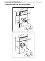
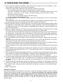
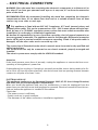
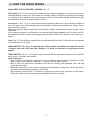
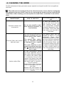
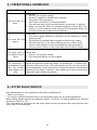
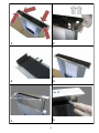
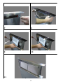
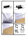
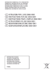
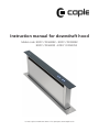
Instruction manual for downdraft hood
Model code: BODY / DD600BK - BODY / DD900BK
BODY / DD600SS - BODY / DD900SS
Contact Caple on 0844 800 3830 or for spare parts www.4caple.co.uk
The symbol
on the product or on its packaging indicates that this product may not be
treated as household waste. Instead it shall be handed over to the applicable collection point
for the recycling of electrical and electronic equipment. By ensuring this product is disposed of
correctly, you will help prevent potential negative consequences for the environment and human health, which could otherwise be caused by inappropriate waste handling of this product.
For more detailed information about recycling of this product, please contact your local city office, your household waste disposal service or the shop where you purchased the product. This
appliance is marked according to the European directive 2002/96/EC on waste electrical and
electronic equipment (WEEE).
CONTENTS
1/ SAFETY INSTRUCTION
- Description of the appliance
4
5
2 / INSTALLING THE HOOD
- Mounting the hood
- Removal of the filter cartridge
- Mounting the filter cartridge
- Electrical connection
6
7
7
8
3 / HOW THE HOOD WORKS 9
4 / CLEANING THE HOOD
11
5 / OPERATIONAL ANOMALIES
12
6 / AFTER SALES SERVICE
12
3
1/ SAFETY INSTRUCTION
Important: keep these instructions for use with the appliance. If the appliance should be
sold or passed on to others, make sure that the instructions are passed on with it. We thank
you for taking note of these suggestions before installing and using the appliance. They have
been written for your personal safety and the safety of others.
These hoods have been designed for personal use in the home. The appliance must be used
by adults. Make sure that children do not come into contact with the appliance and that they
do not use it to play with. Make sure that children do not operate the controls.
-
-
-
-
-
-
-
-
-
-
-
When the appliance is delivered, check the overall appearance of the packaging.
Any remarks should be written on the delivery coupon, of which you keep a copy.
Your appliance is designed for normal domestic use.
It is not designed for commercial or industrial use, or for purposes other than those for which it
was designed.
Any consequences of or damage from incorrect installation or incorrect use of the appliance will
not be covered by the manufacturer’s guarantee.
Repairs must be performed only by an authorised specialist.
Always disconnect the hood before carrying out cleaning or maintenance operations.
Adequately ventilate the area in case the hood is activated simultaneously with other appliances
powered from non-electrical sources so that the hood does not ventilate these combustion
fumes.
It is prohibited to cook food over open flames or operate gas hobs without pots or pans on them
under the hood itself (the flames sucked into the hood might damage the appliance).
Deep frying under the appliance must be done under constant supervision as hot oils and fats
may ignite.
Respect the guidelines for cleaning and replacement of the filters. Accumulated deposits of
grease are a fire hazard.
This appliance must not be used over cook tops powered by wood or coal or in any case, over
cook tops with power levels that could damage the appliance.
Never use steam or high-pressure devices for cleaning your hood (regulations regarding electrical safety).
Never use the hood without the grease filters.
The minimum distance between the open down draft and the surface above it needs to be 400
mm.
When moving the down draft, never place hands inside the operating radius of the pull-out carriage.
The downdraft is equipped with safety switches that block it from functioning, when the front
panel of the grease filters has been disengaged.
Constantly seeking to improve our products, we reserve the right to modify their technical, functional, or aesthetic characteristics as they evolve.
In the case of the version with external motor, for normal downdraft operation, it is necessary
to use an extraction unit (external motor) made by the same manufacturer.
The air collected must not be conveyed into a flue used for smoke or fumes from appliances
powered by anything other than electricity (central heating systems, etc.). As far as concerns
discharging air from the flue, respect the guidelines of the competent authorities.
4
1/ SAFETY INSTRUCTION
- DESCRIPTION OF THE APPLIANCE
75
0 - 1160
12
560 - 86
-1180
580-880
8
300
116
80x230
100
490 -
790 -
1090
75
720
Ø150
200
440
75
0 - 1160
12
560 - 86
-1180
580-880
300
116
720
8
Ø150
340
490 -
790 -
1090
200
5
75
100
440
2/ INSTALLING THE HOOD
1) Before starting the appliance installation, please check that all components are not damaged, in such a
case contact your retailer and do not carry out installation.
Furthermore, please read carefully all of the following installation instructions.
- Use an exhausting pipe whose maximum length does not exceed 5 meters.
- Limit the no. of elbows in the piping , since each elbow reduces the aspiration efficiency of 1 linear
meter. (Ex. : if you use no. 2 x 90 ° elbows, the length of piping l must not exceed 3 meters)
- Avoid abrupt direction changes.
- Use a 150 mm constant diameter pipe for the whole length .
- Use piping approved by standards in force.
Before the installation of the Downdraft, please remove the security piece you can see in the picture
(Fig. 1-2-3-4).
The manufacturer will not be answerable for any capacity or noise problems caused by failure to comply with the above instructions and the warranty will be rendered null and void.
2) Before making the opening, check that there are no structural or other parts inside the cabinet, where
the appliance is to be placed, which could hinder a proper installation. Check that the dimensions of
the Downdraft and the ones of the cooktop are compatible with the cabinet so that the installation can
be carried out properly.
3) Make a rectangular opening, 790 x 100 mm in size, in the back of the cook top for the 90 cm model
and 490 x 100 mm for the 60 cm model and 1090x100mm for the 120cm model.
For models with motor already fitted, remove the screws and the extraction unit to fit the downdraft in
the relevant hole. At this point, insert a seal (silicone) in the bottom section of the frame support (Fig.
18) and place in the relevant hole (Fig. 18-19-20), then proceed to insert the downdraft into the unit.
4) Put the Downdraft in the opening, inserting it from above as shown in Fig. 12.
5) Fix the downdraft inside the cabinet, using the special fixing brackets supplied with the product.
(Fig.13a).
Insert the brackets in the lower side of the downdraft (Fig.13b), in such a way that there is a 2 mm distance between the lower side of bracket and the bottom of the cabinet. (Fig.13c).
This distance will allow the traction to be positioned downwards of the product, at the moment of fixing,
in order to have the stainless steel trim perfectly adhering with the work surface.
Before inserting the screws, please make sure that the appliance is perfectly perpendicular with the work
surface.
6) After completing the installation and connecting the appliance to the mains electricity, lift the downdraft and remove the door block (Fig. 5-6-7). Then open the door (Fig. 8 - 9) and place the filters as
illustrated in Fig. 11.
7) In the version of the Downdraft equipped with motor, install the motor group adjusting the air evacuation direction as required, either downwards or upwards. After installing the motor, connect the air
ducts (Fig. 13). The motor can be fitted either on the front or back side of the downdraft.
8) For versions with outside motor, place the suction unit (outside motor) in a suitable area and fit the
exhaust air flue as illustrated in Fig. 13. Proceed to fit the air outlet ducts between the outside motor and the down draft. Select an air outlet from the five possibilities (Fig. 21) and fit the connection
provided.
9) Put the metallic box containing the electronic components in a place easy to be reached if a technical
assistance is needed (Fig. 14). Connect the electrical connectors of the box to the Downdraft (Fig. 14).
10)For outside motors, connect the motor unit cable to the relevant connector on the electrical components box.
11)Power the appliance.
Downdraft calibration
After having installed the Downdraft, it is necessary to start the calibration procedure, which is aimed at
adjusting the extraction strength of the filtering unit. Connect the product to the power line, making
sure that it is conformed to the supply voltage indicated on the technical data tag. Pushing the ON/1
button (Fig. 22B for SDD2 and 15H for SDD2 TC) the aspiration panel rises. After it has reached a
height of 180 mm from the cooketop, press OFF, to stop the extraction then the Timer and after 2 sec.
the OFF button.
6
The downdraft will carry out the calibration of its aspiration panel rising and retracting for some centimeters. During this phase, the buttons on the push button control panel blink. At the end of the calibration,
the aspiration panel gets back to the previous position and the button stop blinking. Wait until the aspiration panel stops moving before re-activating the extraction.
UTILISATION
This product is intended to extract fumes and fats from cooking. It is designed to work in both suctioning
mode, with outside evacuation, and filtering mode.
EXTERNAL MOTOR VERSION
The hood is equipped with an air outlet to convey smoke outwards (the flue pipe and fixing flange are not supplied).
Check valve blockage
Warning: Before connecting the air exhaust hose, make sure that the check valves are free to
turn over freely.
For hoods with outside air exhaust, fit a check valve to prevent wind and returning air from
entering.
Filtering mode
In case fumes and vapour cannot be evacuated outside, the appliance can be used in the filtering mode.
Carbon filters are required for this type of hood. Air recycled through the charcoal filters is reintroduced into the kitchen, thanks to a duct conveying the air on one side of the cabinet (Fig. 14 bis).
Installation must conform to the regulations in force regarding the ventilation of enclosed environments. In particular, discharged air must not be channelled into a conduit
used for exhaust discharge or discharge from devices that operate with gas or other combustible materials. The use of unused conduits is not permissible without the approval of
a qualified technician.
- GREASE FILTER REMOVAL
- MOUNTING THE CARBON FILTER
The removal and fitting of the grease and carbon filters need to be carried out with the downdraft in the open position. To open the downdraft, push the ON/1 key. Then remove the front
panel, pushing the upper part of each side at the same time. The panel will rotate forwards to
make it possible to access the grease filters (Fig. 16). Remove the grease filters to access the
carbon filters (Fig. 17). IThe replacement of the charcoal filters has to be carried out accordingly to the
effective use of the Downdraft, and in any case at least once every 6 months.
After having replaced the filters, reinstall the front stainless steel panel, otherwise the Downdraft
is not enabled to function.
7
- ELECTRICAL CONNECTION
WARNING: Place the metal box containing the electronic components at a distance of no
less than 65 cm from gas-operated cook tops or in any case, 65 cm from the extraction
point of the hood.
RECOMMENDATION: We recommend installing the metal box containing the electronic
components at least 10 cm above floor level and at a suitable distance from all heat
sources (e.g. oven sides or cook top).
This appliance is fitted with an H05 VVF 3 conductor, 0.75 mm2 (neutral, phase, and
ground) power cable. This can be connected to a 220 – 240 V mono-phase electrical network by way of a CEI 60083 regulation power socket that must remain accessible after
installation, in conformity to installation regulations.
We decline all responsibility in case of accident caused by a lack of ground connection or
incorrect ground connection. The appliance must be fed through a differential protection
device (RCD), with a nominal residual current not exceeding 30mA. If the power cable is
damaged, call the after-sales service to avoid any risk.
The connection of Downdraft to the electric network must be carried out by qualified and
skilled technicians.
The cooker hood can only be connected to one electric network, properly arranged and
installed.
The electric system must comply with the VDE0100 standard.
Attention
If the hood presents some form of anomaly, unplug the appliance or remove the fuse corresponding to the appliance’s power line.
If the appliance has no plug or if the plug is not easily accessible, then a device needs to be fitted to cut it off from the mains electricity; this device must have an opening distance between
contacts on all poles of at least 3 mm.
ELECTRIAL HOOK UP
This appliance conforms to the European Directives 2006/95/EC (Low Voltage Directive)
and 2004/108/EC (Electromagnetic Compatibility).
When you install the appliance and carry out maintenance, it must be unplugged from the
power source or the fuses must be disengaged or removed. Electrical connection must be carried out before the appliance is installed in the cabinet.
Check that:
- The power source is sufficient,
- Power cords are in good condition,
- The diameter of the cables conforms to installation regulations.
8
3/ HOW THE HOOD WORKS
Model SDD2 TOUCH CONTROL VERSION (Fig. 15)
OFF switch: (Fig. 15) It is used to close the aspiration panel completely or to position it at intermediate heights at least mm 180 above the cooktop. While closing the aspiration panel keeps
on working at the speed set up to the height of mm 180 from the cooktop. Below this height
the aspiration function is automatically cut out.
On switch/+: (Fig. 15) It is used to extract the aspiration panel up to the maximum height of
mm. 300 and to set automatically the first aspiration speed when reaching the height of mm
180 from the cooktop.
When pressing the button again after reaching this height, the aspiration motor speed can be
increased.
If the aspiration panel is positioned at an intermediate height between mm 180 and mm 300,
the aspiration panel can start raising again by pressing first the OFF switch and then the On/+.
Switch.
Leds: (Fig. 15) The different speed levels are indicated by blue leds (1. Speed level corresponds
to the led down on the left).
MINUS SWITCH: (Dis. 15) it is working only if the position reached by the aspiration panel
is higher than mm 180 from the cooktop. It is used to decrease the aspiration motor
speed.
TIMER SWITCH: (Fig. 15): it is used to stop automatically the aspiration system and to close the
timer once 10 minutes has expired.
Other functions:
- After 30 hours of appliance operation, the push button panel indicates saturation of the
grease filters by the buttons flashing. To reset, press the timer button.
- After 4 hours of continuous operation from the last setting, the appliance turns off and
closes automatically.
- When the front panel is removed for cleaning and maintenance operations, all the electronic
aspiration and movement functions are locked.
- Anti pinching safety device: if anything is obstructing the closure operation of the downdraft, the operation will stop and the downdraft will move up again.
9
10
4/ CLEANING THE HOOD
Careful maintenance helps guarantee proper operation and good results from an appliance
over time.
The hood must be unplugged from the electrical power source, both by unplugging
the appliance from the socket as well as de-activating the breaker, before removing the
metal filters. After cleaning, you must replace the metal filters as outlined in the instructions.
MAINTENANCE
External surfaces and
accessories
HOW TO PROCEED?
To clean the external surfaces of the hood and the
Do not use metallic scrub- light housing screen use
bers, abrasive products, or only commercially available
household detergents diluthard brushes.
ed in water. Then rinse with
clean water and dry with a
soft cloth.
After 30 hours of functioning, the downdraft will signal the grease filter saturation.
The grease filter saturaCharcoal filter with extract- tion is signalled through
a flashing of the 4 central
able unit open
leds.
The reset function is activated by pushing the timer
key
while the extractable
unit is open.
Active carbon filter
ACCESSORY PRODUCTS TO
USE
In the recirculation mode,
you must substitute the active carbon filter periodically.
To remove the carbon filter
it is necessary first of all to
remove the grease filter and
then to pull the plastic key of
the panel itself to remove it
from its seating.
Follow these steps in reverse
order to insert the active carbon filter.
Replace the used carbon filter on an average of every six
months.
11
The grease filters can be
washed by hand or in the
dishwasher. These filters
need to be cleaned on a regular basis because otherwise
they may present a fire risk.
Refit the grease filters and
front panel, making sure that
the panel is properly fitted at
the sides so that it does not
cause the downdraft to stop
operating.
5/ OPERATIONAL ANOMALIES
SYMPTOM
SOLUTION
Check that:
• There is not a power outage.
• A specific speed has actually been selected.
• The panel is hung properly.
The hood does not
• The 9 pole connection is inserted properly.
work...
• The red reset key, found over the electric system box, is pushed.
• Make sure that the wires are inserted properly in the 9 pole connection, in the connector itself. (During the connection phase, an
excessive pressure could bend the contacts.)
Check that:
• The motor speed selected is sufficient for the quantity of fumes
steam present.
The hood has low
• The kitchen is ventilated well enough to allow for air intake.
output...
• The charcoal filter is not worn (filtering version cooker hood).
• The air outlet channel is free and compliant with paragraph 2.
• The non-return valves of the suctioning unit are free to rotate.
The hood stops in Check that:
the middle of ope- • There is not a power outage.
ration.
• The omnipolar device has not tripped.
The downdraft is
not perfectly in line
with the kitchen
range support surface.
Adjust the position of the body edge , by shifting the “L” brackets positioned in the short sides of the lower body (Fig.24); in order to do it,
lift the downdraft, loosen the screws, change the position until perfect
linearity of the edge is reached , then tighten the screws and put the
downdraft again inside the cabinet.
6/ AFTER SALES SERVICE
Any maintenance on your equipment should be undertaken by:
- Either your dealer,
- Or another qualified mechanic who is an authorized agent for the brand appliances.
When calling, please mention the appliance details (Type Fig. 23a and equipment Fig. 23b and
production date Fig. 23c).
This information is mentioned on the rating label and the production date one placed on the
lower side of the downdraft.
12
1
2
3
4
5
6
13
Pu
sc
h
7
8
9
10
11
14
2mm
12
13
14
14 bis
15
15
16
17
18
19
20
21
16
A
B
C
D
22
A
B
C
23
24
17
E
F
18
Graphics by:
X TYPE ENGINEERING S.r.l
90002004220 - B - 04 /2012