1
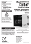
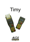
APPENDIX
APPENDIX 1. Warranty Conditions
The following is a summary of the Warranty conditions, but a full version is
available from Atmos.
The Warranty includes:
1. Within the specified time period, the Atmos Warranty covers all
products supplied against any material construction or operation faults
that are found to be of original manufacturing origin, so long as all the
conditions of this warranty have been complied with.
2. The warranty period is for 2 years from the date of invoice, or 12 months
from the date of installation, whichever has the later expiry date. It
covers the replacement of faulty parts and labour, excluding the ignition
electrode, ionisation probe and automatic air vent. .
Atmos gives a 1 year warranty on replacement parts.
3. The warranty period for the heat exchanger and the water heater tank of
the appliance is 5 years, subject to manufacturer’s conditions
4. All products must be used in an appropriate application and manner.
This includes but is not limited to: correct boiler sizing, system design,
system cleansing and use of corrosion inhibitors. Where appropriate and
always in areas of Hard Water(in excess of 200ppm), an approved water
conditioner device must be fitted (in accordance with Building
Regulations).
5. The Benchmark Boiler Commissioning Checklist/Service Record must
be completed and kept up to date, and a copy supplied to Atmos if
required, as proof of correct commissioning and service. In addition the
Warranty card must be completed, and the signed Atmos copy received
by Atmos within 8 days of installation. By signing the Warranty card,
the buyer agrees that the goods have been delivered in a satisfactory
condition.
6. The warranty and guarantee provision shall no longer be valid when it is
established that the defects, damage or excessive wear are due to
improper use or injudicious treatment or to unskilful repair, adjustment,
installation or maintenance by non-approved installers.
7. This warranty shall not apply if the fault is caused by the deposition of
scale, failure or abnormality of gas or water supply, or impact of any
external influence that adversely affects the normal operation of the
product. This shall include but not be restricted to dehydration, abnormal
or high voltage, and hard water.
8. Surface damage and transport damage are outside the scope of this
warranty.
9. The guarantee lapses if the boiler has not had a yearly service by an
approved service agent. The instructions of installation and use that we
supply for the respective appliances must be fully observed.
Note: An extended Warranty period is available as an option from Atmos.
ATMOS MULTI Mk2 version 2008
Appendix Page 1
APPENDIX 2. Spare Parts List
Atmos Multi Mk 2 Parts List
Atmos Multi 24/80
Atmos Multi 24/80 PLUS
Atmos Multi 32/80 PLUS
Atmos Multi 38/80 PLUS
Part Ref.
Drg Ref Description
1
2
3
3.1
3.2
4
5
6
7
8
8
9
10
10
11
11
11.1
11.1
11.2
11.2
11.3
11.3
11.4
12
13
13
13
14
15
15.1
15.2
15.3
15.4
15.5
15.6
16
16
16
16.1
16.2
16.3
16.4
16.5
Wall bracket
Bracket fixing kit
Rear casing
AAV Grommet 15 mm red/brown
Casing latches kit
Locking pin
Air intake pipe
Automatic closing device 3/8"
Automatic air vent 3/8"
Flue gas pipe
Flue gas temp measuring point
Flue pipe
Gas pipe (until end 2006)
Gas pipe (Jan 2007 onwards)
Gas valve & fittings set (until end 2006)
Gas valve & fittings set (see note 2)
(Jan 2007 onwards)
Gas valve (Honeywell VR4605 to end 06)
Gas valve (Honeywell VK4115 Jan 07
on)
(see note 2)
O-Ring 26,57x3,53 (until end 2006)
O-Ring 26,57x3,53 (Jan 2007 onwards)
Bolt M5x8 (until end 2006)
Bolt M5x8 (Jan 2007 onwards)
Nipple 1/2"
Sealing washer
Connecting tube - 24 Model
Connecting tube - 32 Model
Connecting tube - 38 Model
Fixing nut M6
Flow pipe set
Flow pipe
(deleted)
Tightening ring 22 mm
Tightening nut M27x1,5
CH Temperature sensor
Plug 1/2"+ O-Ring
Tank set
Tank set – 24 Plus, 32 Plus Models
Tank set – 38 Plus Model
Tank frame
Earthing washer M8
Hex bolt M8x12
Sealing washer M8
Pump/heat exchanger pipe
ATMOS MULTI Mk2 version 2008
*
*
*
*
*
*
*
*
*
*
*
*
*
*
*
*
*
*
*
*
*
*
*
*
*
*
*
*
*
*
*
*
*
*
*
*
*
*
*
*
*
*
*
*
*
*
*
*
*
*
*
*
*
*
*
*
*
*
*
*
*
*
*
*
07.98.37.043
07.95.82.006
07.90.22.080
07.98.68.026
07.90.82.009
07.98.43.018
07.98.74.298
75.06.65.001
79.40.26.001
07.98.74.295
07.95.15.002
07.98.74.286
07.98.74.282
07.98.74.411
07.95.00.002
07.95.78.005
*
*
*
*
*
*
*
*
07.98.78.003
07.98.78.023
*
*
*
*
*
*
*
*
*
*
*
*
*
*
*
*
*
*
*
*
*
*
*
*
*
*
07.98.83.190
07.98.83.166
82.27.02.908
82.08.93.046
07.98.74.312
07.98.83.189
07.95.74.024
07.95.74.025
07.95.74.038
07.98.82.120
07.95.00.003
07.98.74.283
75.66.99.027
07.98.74.155
07.98.82.119
07.98.63.042
74.53.80.016
07.95.05.008
07.95.05.009
07.95.05.015
07.98.30.006
07.98.82.114
07.98.82.112
82.74.06.903
07.98.74.285
*
*
*
*
*
*
*
*
*
*
*
*
*
*
*
*
*
*
*
*
*
*
*
*
*
*
*
*
*
*
*
*
*
*
*
*
*
*
*
*
*
*
*
*
*
*
*
*
*
*
*
*
*
*
Appendix Page 2
Atmos Multi Mk 2 Parts List
Atmos Multi 24/80
Atmos Multi 24/80 PLUS
Atmos Multi 32/80 PLUS
Atmos Multi 38/80 PLUS
Drg Ref
16.6
16.7
16.8
16.9
16.10
16.11
16.12
16.13
17
18
19.1
19.2
19.3
19.4
19.5
19.6
19.6
19.7
19.8
19.8
19.9
19.10
19.10
19.10
19.11
19.12
19.13
20
20
21
21
22
23
24
25
26
27
27
28
28
29
30
31
32
33
34
35
35
36
Description
Union nut 1"
O-Ring 22x3.0
Bracket bolt
Silicone sealing ring
Adjusting screw M6x25
Support collar 22 mm
Earthing tab 6,3 mm 45°
Screw M4x8 self tap
Thermostat
Rear insulation
Burner casting
Fan casing
Fan
Nut M4
Viewing glass set
Burner set for 24 & 32 Models
Burner set for 38 Model
Ionisation probe set
Ignition electrode set
Sealing ring for ionisation/ignition
electrode
O-Ring 80x2
Mixing chamber 25 mm - 24 Model
Mixing chamber 28 mm - 32 Model
Mixing chamber 30 mm - 38 Model
Screw M6x8
Grommet 15 mm
Nipple cover Ø 6 mm
Ceramic core
Extension piece for 32 Plus, 38 Plus
Mid baffle for 24, 24 Plus
Mid baffle for 32 Plus, 38 Plus
Lower baffle
Condensate collector
Siphon 32x140 mm
Sealing washer 60 mm
Lifting bar set
CH pump (inc. cable loom K5)
CH pump (inc. cable K5) for 38 Plus
3 Port valve (inc. cable loom K7)
3 Port valve actuator
Return pipe for CH pump
Pressure sensor
Pump seal 30 mm
Union nut 1"
Short pipe for pump
T-piece 22x22x22 mm
Pipe with bend - pump
Pipe with bend – helix coil
Elbow connection 22x22 mm
ATMOS MULTI Mk2 version 2008
*
*
*
*
*
*
*
*
*
*
*
*
*
*
*
*
*
*
*
*
*
*
*
*
*
*
*
*
*
*
*
*
*
*
*
*
*
*
*
*
*
*
*
*
*
*
*
*
*
*
*
*
*
*
*
*
*
*
*
*
*
*
*
*
*
*
*
*
*
*
*
*
*
*
*
*
*
*
*
*
*
*
*
*
*
*
*
*
*
*
*
*
*
*
*
*
*
*
*
*
*
*
*
*
*
*
*
*
*
*
*
*
*
*
*
*
*
*
*
*
*
*
*
*
*
*
*
*
*
*
*
*
*
*
*
*
*
*
*
*
*
*
*
*
*
*
*
*
*
*
*
*
*
*
*
*
*
*
*
*
*
*
*
*
*
*
*
*
Part Ref.
07.98.82.113
07.98.83.227
07.98.43.017
07.98.83.231
07.98.82.117
07.98.74.206
68.31.12.828
82.08.93.046
78.76.54.981
07.98.83.229
07.98.07.008
07.98.83.185
07.98.36.003
07.98.82.080
07.95.26.003
07.95.25.002
07.95.25.007
07.95.78.004
07.95.70.006
07.98.83.226
07.98.83.184
07.98.16.002
07.98.16.001
07.98.16.005
07.98.82.082
07.98.68.041
07.98.15.092
07.98.27.001
07.98.27.003
07.98.41.027
07.98.41.031
07.98.41.030
07.98.07.007
07.90.74.200
07.98.83.233
07.95.74.023
07.95.36.002
07.95.36.003
75.83.01.004
75.83.01.006
07.98.74.284
07.98.78.004
07.98.83.230
07.98.82.113
07.98.74.288
07.98.74.304
07.98.74.296
07.98.74.287
74.64.30.958
Appendix Page 3
Atmos Multi Mk 2 Parts List
Atmos Multi 24/80
Atmos Multi 24/80 PLUS
Atmos Multi 32/80 PLUS
Atmos Multi 38/80 PLUS
Drg Ref
37
38
39
40
40
41
42
43
44
44
45
46
47
47
47
47
48
100
101
102
103
103
103
103
104
105
106
106
107
108
109
110
111
112
Note 1
Note 1
Description
Front insulation
Flow pipe
Bracket
Ignition transformer (until end 2006)
Ignition transformer (see note 2)
(Jan 2007 onwards)
Screw M4x8 self tap
Hex bolt M8x12
Controller mounting plate
Controller with front plate
Controller
Controller front plate
Front case set
Data Plate 24 Model
Data Plate 24 Plus Model
Data Plate 32 Plus Model
Data Plate 38 Plus Model
Screw M3x 25
Cable loom K1 (room thermostat)
Cable loom K2 (pressure sensor)
Cable loom K4
(CH flow & tank temp sensors)
Appliance selection 24 Model
Appliance selection 24 Plus Model
Appliance selection 32 Plus Model
Appliance selection 38 Plus Model
Tank temperature sensor
Cable loom K5 (CH pump)
Cable loom K6 (Gas valve, max.
thermostat, Ionisation/ Ignition electrode)
(until end 2006)
Cable loom K6 (Jan 2007 onwards)
(see note 2)
Cable loom K7(included with 3 port
valve)
Cable loom K8 (fan)
Cable K11 (main boiler earth)
Cable loom K12 (ignition earth)
(Jan 07 onwards: included with item 40)
Cable loom K13 (ignition)
Mains lead
Temp. & pressure relief valve
Temp. & press. valve discharge pipe
*
*
*
*
*
*
*
*
*
*
*
*
*
*
*
*
*
*
*
*
*
*
*
*
*
*
*
*
*
*
*
*
*
*
*
*
*
*
*
*
*
*
*
*
*
*
*
*
*
*
*
*
*
*
82.08.93.046
07.98.82.112
07.95.30.001
07.90.80.028
07.95.64.001
07.90.80.023
07.95.22.004
07.98.35.294
07.98.35.295
07.98.35.297
07.98.35.321
07.98.82.115
07.98.66.178
07.98.66.206
07.98.66.212
*
*
*
*
*
*
*
*
*
*
*
*
*
*
Part Ref.
07.98.83.228
07.98.74.308
07.98.37.042
07.98.61.001
07.98.61.002
*
*
*
*
*
*
*
*
*
*
*
*
*
07.98.63.043
07.98.63.044
07.98.63.046
07.98.63.053
07.98.63.047
07.98.66.208
07.98.66.202
*
*
*
*
07.98.66.228
*
*
*
*
-
*
*
*
*
*
*
*
*
*
*
*
*
07.98.66.201
07.98.66.207
07.98.66.204
*
*
*
*
*
*
*
*
*
*
*
*
*
*
*
*
07.98.66.210
07.98.66.120
07.92.64.032
07.99.74.537
*
*
*
Note 1 – This part is not shown in the diagrams. Please refer to the Boiler Schematic (Section 4).
Note 2 – The gas valve and fittings including the ignition transformer have been changed to new
components, and the ignition transformer is now fitted onto the valve.
ATMOS MULTI Mk2 version 2008
Appendix Page 4
ATMOS MULTI Mk2 version 2008
Appendix Page 5
ATMOS MULTI Mk2 version 2008
Appendix Page 6
ATMOS MULTI Mk2 version 2008
Appendix Page 7
ATMOS MULTI Mk2 version 2008
Appendix Page 8
ATMOS MULTI Mk2 version 2008
Appendix Page 9
APPENDIX 3. Fault Finding
1. GENERAL
The Atmos Multi has 3 types of error messages:1. Warning messages
In this case, instead of the status message, a letter appears on the diagnostic display for one second, once every 5
seconds.
2. Blocking messages
A permanently illuminated letter appears on the diagnostic display.
3. Malfunction messages
A flashing letter or number appears on the diagnostic display.
In the event of a warning message, the function to which the message applies will be switched off while the appliance
continues to operate.
In the event of a malfunction message, the entire appliance will be shut down requiring manually resetting before the
boiler will continue operation.
OPERATING CODES ON ATMOS MULTI
See also Table 1 in Section 5 of the Manual. The following appear on the status display:1
2
3
4
Hot water heating operating
Central heating operating
Hot water and central heating – priority to hot water
Hot water and central heating - supply to both
The dot in the bottom right hand corner of the diagnostic display indicates the following burner function:No dot
Slow flashing dot
Increasingly fast flashing dot
Constant dot
No burner
Minimum fire
Higher & higher firing
Burner on maximum output
The dot in the bottom right hand corner of the central heating display: Dot
ATMOS MULTI Mk2 version 2008
Motorised valve energised to send
water to the central heating circuit
Appendix Page 10
2. SUMMARY OF MESSAGES
This section provides a brief description of the warning, blocking and malfunction messages which appear on the
appliances diagnostic display. The causes of these messages are addressed in more detail in section 3.
2.1 Warning messages
A warning message is identified by a letter that appears on the diagnostic display once every 5 seconds, for a period of
1 second, instead of the status message.
Diagnostic display code
Status
Warning every 5
seconds
message
(Number)
b
c
8
d
h
Message
o
o
Incorrect hot water tank temperature reading, value<-10 C or> 118 C
Incorrect central heating water pressure, value between 0 and 0.5 bar or 3 and
4 bar (capacity is limited to low setting)
o
o
Incorrect central heating return sensor reading, value<-10 C or> 118 C
o
o
Incorrect outside sensor reading, value<-15 C or>118 C
2.2 Blocking messages
A blocking is an error that occurs without causing a malfunction. The appliance waits until the blocking has been
resolved and then continues to operate normally. A blocking is indicated by a permanently lit letter on the diagnostic
display.
Diagnostic
display
c
Code
Central heating
water display
HH
LL
C*
F
H
L
n
t
HH
LL
10
11
20
21
31
Message
o
Central heating water temperature sensor error value >118 C
o
Central heating water temperature sensor error, value <-10 C
Central heating pressure lower than 1 bar (occurs when the plug is inserted
into the power socket)
Mains frequency error
Internal error
Electrical mains plug error-correct supply polarity
Mains or reference voltage too low
o
Appliance type recognition error, value >118 C
o
Appliance type recognition error, value <-10 C
Appliance type recognition error, control unit is set to 24/80
plus
Appliance type recognition error, control unit is set to 24/80
Appliance type recognition error, control unit is set to 32/80
plus
Appliance type recognition error, control unit is set to 32/80
plus
Appliance type recognition error, control unit is set to 38/80
* this code will not be stored in the memory
ATMOS MULTI Mk2 version 2008
Appendix Page 11
2.3 Malfunction messages
A malfunction is an error which is so serious that the appliance is locked. A malfunction message is identified by a
locked control unit accompanied by a flashing number or letter on the diagnostic display. The appliance can only be
unlocked by pressing the reset button.
Diagnostic
display
2
3
3.
4
4.
6.
7
7.
8
Code
Central heating
water display
9
9.
Letter
(Dark display)
Message
Fan defective (5Hz deviation per minute)
Incorrect ionisation (flame) signal
No ionisation (flame) signal during start-up procedure
Ionisation signal absent during heat supply (diagnostic code 1-4)
Ionisation signal remains present too long after heat supply
Gas valve control defective
Insufficient flow of central heating water during hot water heating
Insufficient flow of central heating water during radiator heating
Maximum thermostat cuts out and central heating water pressure was lower
than 0.5 bar
Maximum thermostat cuts out and central heating water sensor was higher
o
than 80 C
Safety internal malfunction in control unit
Internal malfunction in control unit
Appliance receiving no voltage
3. CAUSES OF MESSAGES
3.1 Warning messages
A warning message is identified by a letter that appears on the diagnostic display every five seconds for a period of one
second instead of the status message. The appliance continues to operate, but the function to which the message applies
will be switched off of ignored. Once the cause of the warning message has been solved, the appliance will start up
again automatically so resetting is not necessary. The possible causes are described below in order of probability. Also
look for the malfunction in this order.
Status
message
(Number)
Diagnostic display code
Diagnosis
Warning
every 5
seconds
o
Hot water tank temperature <-10 C or
o
>118 C. In sub-program sensor values
o
the message HH (>118 C) or LL (<b
o
10 C) appears on the central heating
water display.
Message
HH
LL
Central heating water display code
Cause
x
x
x
x
x
x
x
x
x
ATMOS MULTI Mk2 version 2008
o
Central heating temperature >118 C
Connector K4 loose or improperly
connected
Temperature sensor wiring interrupted
Sensor defective
Control unit
o
Control heating temperature <-10 C
Short circuit in temperature sensor
wiring
Sensor defective
Control unit
Appendix Page 12
Central heating water pressure too low
or too high. Limiting the output to the
appliances lowest capacity. The
current central heating water pressure
is shown on the central heating
display. If the central heating water
temperature is set on the central
heating display, the current central
heating water pressure can be read
through ‘sub-program sensor values’
c
0 – 0.5
BAR
x
HH
x
Central heating system lacking water
pressure
No venting of the central heating
system through the automatic deaerator
Leak in the appliance or central
heating system
Central heating pressure sensor
defective
Central heating system over
pressurised
Expansion tank defective
Central heating pressure sensor
defective
See cause of HH in status message
LL
x
See cause of LL in status message
HH
x
See cause of HH in status message
LL
x
See cause of LL in status message
x
x
x
3 – 4 BAR
x
x
x
Central heating return temperature
o
o
<-10 C or >118 C. In sub-program
o
sensor values, HH (>118 C) or LL (<o
10 C) will appear on the central
heating water display.
o
o
Outside temperature<-10 C or >118 C.
In sub-program sensor values,
o
o
HH (>118 C) or LL (<-10 C) will
appear on the central heating water
display.
d
h
3.2 Blocking messages
A blocking message is identified by a permanently illuminated letter on the diagnostic display. Once the blocking has
been solved, the appliance will start up again automatically. So resetting is not necessary.
The possible causes are described below in order of probability. Also look for the malfunction in this order.
Code
Diagnostic
display
c
Diagnosis
Central heating
water display
HH
LL
Cause
x
x
x
See cause of HH in ‘status message/b’ [3.1]
See cause of LL in ‘status message/b’ [3.1]
Central heating pressure lower than 1 bar
F
Central heating water temperature > 118°C
Central heating water temperature < -10°C
Appliance blocked because central heating
system pressure is too low
Mains frequency error
x
H
Internal error
x
L
Electrical mains supply
n
Mains or reference voltage too low
x
x
x
x
x
x
x
x
x
x
If this blocking occurs frequently or for a
long period, replace control unit
If this blocking occurs frequently or for a
long period, replace control unit
Mains supply has wrong polarity
Not earthed
Ionisation electrode earth wire loose
Control unit
Mains voltage < 200 volts
Mains voltage insufficient
Control unit
Control unit selected incorrectly
Selection resistance defective
Control unit defective
C*
t
HH
Appliance type recognition error, value >
118°C
LL
Appliance type recognition error, value < 10°C
Appliance type recognition error, the control
unit is set to 24/80
Appliance type recognition error, the control
plus
unit is set to 24/80
Appliance type recognition error, the control
unit is set to 32/80
Appliance type recognition error, the control
plus
unit is set to 32/80
Appliance type recognition error, the control
plus
unit is set to 38/80
10
11
20
21
31
* this code will not be stored in the memory
ATMOS MULTI Mk2 version 2008
Appendix Page 13
3.3 Malfunction messages
A malfunction message is indicated by a flashing number or letter on the diagnostic display combined with a locked
control unit. Once the malfunction is solved, the control unit must be unlocked by pressing the reset button once.
Should the control unit fail to unlock, try again after approx. 20 seconds.
The possible causes are described below in order of probability. Also look for the malfunction in this order.
Code
Diagnostic
display
2
Diagnosis
Fan defective (5 hz deviation per
minute)
3
Incorrect ionisation (flame) signal
3.
No ionisation (flame) signal during
start-up procedure
Cause
x
x
x
x
x
x
x
x
x
x
x
x
4
4.
6
Ionisation signal lost during heat
supply (diagnostic code 1 - 4)
Ionisation signal remains too long
after heat supply
Gas valve control receiving voltage
erroneously
ATMOS MULTI Mk2 version 2008
x
x
x
x
x
x
x
x
x
x
x
x
x
Fan not turning
Fan’s electrical connection loose or improperly connected
Control unit
Valve in gas valve remains open or leaks
Control unit
No gas supply
gas tap closed
gas valve defective
gas valve’s electrical connection loose or improperly connected
Air supply obstructed
Flue tube obstructed
Siphon obstructed
Ionisation cabling not in order
Ionisation probe defective or causing short-circuit such as against burner
No ignition
ignition transformer electrical connection loose or improperly
connected
power cable defective
ignition electrode defective or causing short-circuit
Control unit
Insufficient gas supply
Siphon obstructed
Ionisation electrode defective / causing short-circuit such as against
burner
Gas valve set incorrectly
O2 content more than 7.5% at low setting
Fan’s low capacity circuit defective or interrupted
Burner damaged
Control unit
Valve in gas valve defective, remains open or leaks
Control unit
Wiring error
Control unit
Appendix Page 14
Malfunction messages (continued)
Code
Diagnostic
display
Diagnosis
7
Insufficient circulation
of central heating
water during hot water
heating
Cause
x
x
Insufficient central heating water in the central heating water circuit
- Central heating water pressure too low (minimum 1 bar at the
appliance)
-Automatic de-aerator not functioning properly (air in the appliance)
Central heating pump not running
- Central heating pump stuck
- Connector K5 loose
- Central heating pump defective
- Thermal safety switched off
- Control unit
Insufficient central heating water in the central heating water circuit
- Central heating water pressure too low (minimum 1 bar at the
appliance)
- All (thermostat) radiator taps are closed (pressure difference regulator
not set properly if present)
- Accumulation of air caught somewhere in the central heating water
circuit
-Automatic de-aerator not functioning properly (air in the appliance)
Central heating pump not running
- Central heating pump stuck
- Connector K5 loose
- Central heating pump defective
- Control unit
Central heating water pressure incorrect
Central heating water temperature sensor not properly connected to central
heating water pipe
Thermal safety connection defective
Thermal safety defective
Control unit
Central heating pump not running
- Central heating pump stuck
- Connector K5 loose
- Central heating pump defective
- Control unit
Central heating water temperature sensor not properly connected to central
heating water pipe
Thermal safety connection defective
Thermal safety defective
Control unit
Central pump not running
- Central heating pump stuck
- Connector K5 loose
- Central heating pump defective
- Control unit
Control unit
x
Control unit
x
x
x
x
x
x
Plug not inserted in wall socket
No electricity from wall socket
Wire loom connector k6 not connected
Control unit fuse defective
Mains voltage wiring defective
Control unit
x
7.
Insufficient circulation
of central heating
water during radiator
heating
x
x
8
9
9.
LETTER
[Dark
display]
High limit thermostat
switches off and
central heating water
pressure lower than
0.5 bar
High limit thermostat
switches off and
temperature of central
heating water sensor
o
exceeds 80 C
Control unit safety
malfunction
[Letter such as A or E]
Internal error in control
unit.
Appliance not
receiving any power
ATMOS MULTI Mk2 version 2008
x
x
x
x
x
x
x
x
x
x
x
Appendix Page 15
4. USER PROGRAM
The user program is identified by a permanently lit letter followed by a dot.
x
x
x
x
Access
Next setting
Different value
Exit program
Diagnostic
display
b.
C.
F.
G.
0.**
S.
*
**
:
:
:
:
Press ‘Set’ button for approx. 5 seconds until the letter b. appears
Press ‘Set’ button
Press ‘Hot water’ button
Press ‘Reset’ button
Code
Central heating
water display
01
02
03
88
0. 0
8. 8
88
88
00
01
02
00
01
Function
Setting
Hot water tank temperature
Central heating temperature
Central heating pressure sensor is not active
Central heating pressure
Serial number + last malfunction
Serial number + last blocking
Weather-dependent regulation
60°C
*65°C
70°C
°C
*BAR
*Off
Room thermostat
Timer switch
Non-standard setting (only applies to User program)
Return to standard* (only applies to User program)
standard
only visible if outside temperature sensor is connected
5. INSTALLER PROGRAM
The Installer program is identified by a permanently illuminated letter without a dot.
x
x
x
x
x
Access
Different value
Next setting
Exit program
To sub-program
Diagnostic
display
A
b
c
C
E
F
G
*
:
:
:
:
:
Code
Central heating
water display
88
LL
HH
5b
00
11
60
75
90
00
11
8
88
88
88
8
88
88
88
Press ‘Set’ button for approx. 10 seconds until the letter A appears
Press ‘Hot water’ button
Press ‘Set’ button
Press ‘Reset’ button
Press ‘Set’ button followed by ‘Hot water’ button
Function
Fictitious ionisation flow
Low capacity (continuous)
High capacity (continuous)
To sub-mode sensor values
Modulate at central heating temperature
Central heating water temperature (maximum)
Three-way valve capacity control
Malfunctions (maximum 15)
- 8 = service identification number (0 - 6)
- 8 = malfunction code
Blocks (maximum 16)
- 8 = service identification number (0 - 6)
- 8 = blocking code
Setting
Off
*On
60°C
75°C
*90°C
Off
*On
Begin/end
Last malfunction code
Last malfunction code -1
etc.
Begin/end
Last blocking code
Last blocking code -1
etc.
standard
ATMOS MULTI Mk2 version 2008
Appendix Page 16
Diagnostic
display
h
H
L
n
0**
P
Q
S
Code
Central heating
water display
01
03
05
0. 1
0. 2
0. 3
0. 4
1. 0
24
00
05
10
15
00
02
05
10
5b
00
03
06
5
10
15
20
00
11
t***
Y
10
11
20
21
31
7
15
24
10
21
32
11
24
38
*
**
***
Function
Setting
Pump over-run for central heating
* 1 min.
3 min.
5 min.
*10 min.
20 min.
30 min.
40 min.
1 hour
Continuous
off
5 min.
* 10 min.
15 min.
off
2 min.
5 min.
*10 min.
Last blocking code
off
*3 min.
6 min.
5°C
*10°C
15°C
20°C
Pump over-run for boiler
Low capacity burner time
Central heating acceleration
To sub-program weather-dependent setting
Anti-cycling central heating
Frost-protection (internal on central heating water)
Non-standard setting
(only applies to service program)
Return to standard
(only applies to service program)
Appliance recognition 24/80
plus
Appliance recognition 24/80
Appliance recognition 32/80
plus
Appliance recognition 32/80
plus
Appliance recognition 38/80
Capacity limitation for central heating supply 24/80 and
plus
24/80
Capacity limitation for central heating supply 32/80 and
plus
32/80
Capacity limitation for central heating supply 38/80
plus
7.5 kW
15 kW
*24.5 kW
10 kW
21 kW
*32 kW
11 kW
24 kW
*38 kW
standard
only visible if outside temperature sensor is connected
with the proper selection, the code t will not be visible in the service program
ATMOS MULTI Mk2 version 2008
Appendix Page 17
6. SERVICE SERIAL NUMBER
Every malfunction is preceded by a service identification number. The service identification number is a handy tool for
servicing the ATMOS MULTI. By changing this number after every service, the next time, one can see which blocks
and/or malfunctions occurred since the last service.
To change the service identification number, the malfunction logbook F must first be selected. Then the ‘Hot water’
button is kept pressed in while finally the ‘Set’ button is pressed.
The service identification number will be increased by 1 to a maximum of 6, and will then start again from the number
0. When changing the service identification number, it is simultaneously changed in the blocking logbook.
The example below shows the logbook codes in the CH Water display, obtained by stepping through the most recent
logged faults using the ‘Hot water’ button.
Example
x
x
x
*
**
***
OCT ‘05
OCT ‘06
INSTALLATION OF THE APPLIANCE
CONTENTS OF MALFUNCTION LOGBOOK
CONTENTS OF BLOCKING LOGBOOK
ANNUAL INSPECTION
CONTENTS OF MALFUNCTION LOGBOOK
CONTENTS OF BLOCKING LOGBOOK
SERVICE ID NUMBER INCREASED BY MEANS OF
‘HOT WATER’ AND ‘SET’ BUTTON
OCT ‘07 ANNUAL INSPECTION
CONTENTS OF MALFUNCTION LOGBOOK
CONTENTS OF BLOCKING LOGBOOK
SERVICE ID NUMBER INCREASED BY MEANS OF
‘HOT WATER’ AND ‘SET’ BUTTON
DIAGNOSIS
CENTRAL HEATING WATER DISPLAY
F
G
00-
F*
G**
00-
07.
0c
0-
1-
11-
13.
0c
1-
2-
F***
G
07.
0-
0-
07.
1-
07
1-
Two times 07. means insufficient central heating water flow during central heating operation.
One 0c means for example that the central heating water temperature connector was loose.
Malfunction 13 was added in the second year. This can be seen by the first number 1 (service identification
number). The second number 3. is the malfunction (in this case no ionisation signal during start-up procedure).
The two last malfunctions are preceded by a different service number and are therefore from the previous
services.
COMMENT!
Do not forget to increase the service identification number after each service/maintenance and record this with the date
on the service chart of the appliance.
ATMOS MULTI Mk2 version 2008
Appendix Page 18
ATMOS MULTI Mk2 version 2008
Appendix Page 19
ATMOS MULTI Mk2 version 2008
Appendix Page 20
ATMOS MULTI Mk2 version 2008
Appendix Page 21
ATMOS MULTI Mk2 version 2008
Appendix Page 22