1
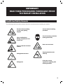
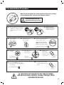
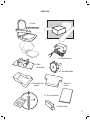
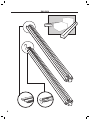
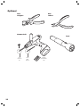
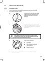
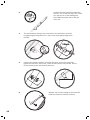
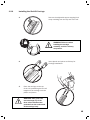
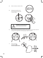
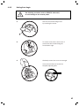
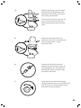
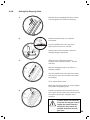
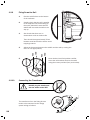
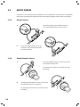
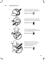
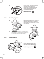
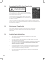
BROOKS STAIRLIFTS
SUPERGLIDE 120
INSTALLATION
PROCEDURES
CONTENTS
Health And Safety Hazards
3
Unpacking the Stairlift Carriage
4
Pre-Installation Procedure
5
Box Contents
6
Installation Tools
9
1.1
9
10
Required
Optional
Installation
1.2
1.3
2
11
Installation Procedure
11
1.2.1
1.2.2
1.2.3
1.2.4
1.2.5
1.2.6
1.2.7
1.2.8
1.2.9
1.2.10
11
12
13
15
17
19
20
23
24
24
Preparation on Site
Joining the Rail
Installing the Rail
Installing the Stairlift Carriage
Setting Seat Angle
Setting Footrest Angle
Installing the Seat
Setting Top Stopping Point
Fixing Down the Rail
Connecting the Transformer
Safety Checks
26
1.3.1
1.3.2
1.3.3
1.3.4
1.3.5
1.3.6
1.3.7
1.3.8
1.3.9
1.3.10
26
26
27
28
28
29
29
29
29
29
Check Controls
Check Remote Controls
Check Safety Sensors
Check Stopping Limits
Check Seat Swivel
Check Battery Isolation Switch
Check Key Switch
Hand Winding
Labelling
Check Correct Fixing of Carriage to Rail
1.4
Demonstrate Stairlift to User
30
1.5
Maintenance
30
1.6
Avoiding Unsafe Installations
30
IMPORTANT!
READ THESE PROCEDURES THOROUGHLY PRIOR
TO STAIRLIFT INSTALLATION
Health And Safety Hazards
The following health and safety hazards should be considered when installing the stairlift:
The risk of loose clothing
or body parts getting
trapped
Injury resulting from
drilling, inappropriate use
of tools etc
Direct or indirect electrical
contact
Falling down the stairs
Falling tools
Correct manual handling
procedure.
Use of necessary protection
(safety glasses etc)
Never use worn tools
Tripping hazards on the
stairway
Follow the current
regulations regarding safe
working practices
3
Unpacking the Stairlift Carriage
WARNING! Take care when handling the carriage assembly,
as this is a heavy component.
Before unpacking carriage it is recommended if possible to
unpack box at Top of Stairway using Brooks PACKING/
UNPACKING INSTRUCTIONS provided.
PLEASE READ PACKAGE INSTRUCTIONS BEFORE REMOVING THE CARRIAGE FROM BOX
1
2
3
4
4
Pre-Installation Procedure
����������������������������������
��������������������������������������������������������������
������������������������������������������������������
�������������������������
����������������������������
��� ��������������������������������
��� ������������������
�
��� ��������������������
��������������
�
��� �������������
�
��� �����������������
����������
�
�
��������������
��������������
����������������
����������������������������
�
�
�����������
������������������������
�
�
�
�
���
���������������
������������������������������������
�
������������������������������������
�
�����������������
�������
������������������������������������
��� Open
������������������
the bag that
�
�
������ ���������������������������������
�
����������������������������
�
��������
�
���������������������
�
���
�
�
�
�
�
�
�
��
�
�
contains
the remotes,
����������������������
batteries
and keys.
��������������������
������������
������������������������������
������������������������
����������������������������
�����������������������������
�������������������������������
�����������������������������������
���
�
�
�
�
����������������
������������
����������������
������������������
���������������
���� ������������������������
�������� ������������������������
�
���������������������
�������������������������������������������
���������������������������������������������
������������������
5
Box Contents
CARRIAGE BOX
�����������
��������������
�����������������
����������
�������������
���������������
�������
�����������
����������������
������������������
������������
����������������
���������������
������������
����������
6
SEAT BOX
�������
��������������
��������
�������������
�������������
��������������
������������
�����������
����������
��������������
�����������
7
RAIL BOX
8
Installation Tools
Required
Open / ring
Spanner
Flat electrical
terminal
screwdriver
Nº2 / Nº3
Philips
screwdriver
Socket
10mm
13mm
17mm
Socket
ratchet
Spirit
Level
Socket
extension
Knife
Tape
Measure
9
Optional
Wire
strippers
Side
cutters
Hammer Drill
7mm
masonry
bit
10
3mm
HSS
drill bit
Torch
Philips
Screwdriver
bits
1.2
INSTALLATION PROCEDURE
1.2.1
Preparation on Site
It is recommended that the following examinations be carried out prior to taking
the rail into the end users’ property:
1.
Visually check the site making sure that all
obstructions such as window sills, pipes,
bulkheads, newel posts etc have been
allowed for.
2.
Examine the stairs, remove any removable
objects that may get damaged or could cause
a tripping hazard when the rail is brought into
the property.
If the stairway is open plan or there is access to the rear of the
installation (not against a wall), then the installation must not go
ahead until the access has been panelled off.
3.
Identify existing damage to:
Decorations
Floor coverings, furniture and
other furnishings
Windows, doors, etc
4.
Do not remove the handrail until the rail has been installed, in case of
mis-measure / abort.
11
1.2.2
Joining the Rail
The stairlift rail is shipped in two pieces that are spliced together during installation.
The upper and lower charge points and upper and lower stopping limit ramps are installed
on the rail sections at the factory.
Before positioning, it is recommended, whenever possible, to join the
rail together at the base of the stairway making assembly easy.
1.
On the bottom rail, loosen the 3 pinch bolts and slide out the 1 inch square
joint-bar until it protrudes approximately 4 ½ inches. Tighten the 3 pinch bolts.
������������
����
����
����
2.
3.
On the upper section of the rail, temporarily
remove the screw from where the gear rack
will go when fully assembled.
Connected to the lower charge point and
running through the inside of the lower rail
section is a two wire cable that terminates
with two female wire connectors.
Connect the male and female wire
connectors of the rail cable together
(brown to brown, blue to blue).
12
The two rail sections now need to be fixed
together.
4.
IMPORTANT!
Make sure that the wiring
isn’t trapped between the
edges of the rail preventing
a flush join.
Re-tighten the pinch bolts to hold
the joint-bar securely in place,
using 2 x 10mm spanners.
5.
Replace the screw into the gear
rack and back into the upper rail.
��
Do not remove the handrail until the rail has been installed,
in case of mis-measure / abort.
1.2.3
Installing the Rail
1.
Position the rail as one complete assembly on the staircase, with the lower
(angled) end resting on the floor, at the bottom of the stairs and the steel
toothed rack uppermost. Place the rail end on the bottom of the rail.
�
��������
�������������
��������������
�����������
13
2.
3.
Position the stair brackets underneath
the rail - one on the first step, one on the
very top step or on the landing and
the middle two either side of the join
in the rail.
The stair brackets clamp to the underside of the rail and are secured
by tightening the long 13mm nut / bolt, which runs right through each
bracket.
13mm
4.
5.
14
Position the bracket so that it’s footrest sits firmly on the stair tread and
tighten the two short 13mm nut / bolts on either side of the bracket. Do not
fix the bracket to the stair tread at this time.
With the rail correctly sitting on the stairs the
handrail if fitted can now be removed.
1.2.4
Installing the Stairlift Carriage
�
WARNING! Take care when
handling the carriage
assembly, as this is a heavy
component.
Insert plastic end pieces to Rail top for
Carriage installation.
2.
3.
�
Remove the adjustable upper stopping limit
ramp moulding from the top end of the rail.
1.
Place the carriage on the top
of the rail, positioning the two rail
lengths on the carriage onto the
plastic end pieces.
WARNING! Take great care
not to damage any of the
three micro-switches that
protrude from the underneath
of the carriage body
15
4.
Switch on Battery isolation switch.
5.
Hold down seat switch, and
drive Carriage onto Rail using
a remote control.
Remember to remove the plastic end
pieces from the top of the rail.
16
6.
Remove yellow warning labels and transit screws attached to both upper and lower
carriage safety edges then fit blanking plugs supplied into holes.
7.
Remove the Safe
Handling Aid. SEE
PACKING INSTRUCTIONS.
1.2.5
Setting Seat Angle
The following procedure must be STRICTLY adhered to,
to avoid damage to the chassis plates.
1.
Remove the footrest hinge cover
by removing the screw.
2.
To remove main cover, remove the 2
screws that are located along the
front bottom edge.
3.
Gradually remove the cover on an angle.
It may be necessary to loosen the
footplate adjusting bolt.
17
18
4.
Loosen the 6 horizontal bolts (3 either side)
until the post can just move.
5.
Adjust the seat to the correct angle
by placing a spirit level on the seat
post platform.
6.
Ensure that the anti-slip clamps (butterfly
brackets) are in the correct horizontal
position. The serrated side should be facing
inward towards the carriage, with the smooth
side facing outward.
7.
Tighten the 6 horizontal bolts using a
13mm socket torque wrench set to
35Nm.
8.
1.2.6
Replace the carriage cover and replace
the two screws.
Setting Footrest Angle
1.
Loosen the centre bolt and adjust to the
correct level using the spirit level.
Once level, tighten the bolt back up.
2.
Return the footrest hinge cover
by replacing the screw.
19
1.2.7
Installing the Seat
The seat assembly now needs to be fitted to the seat post on the carriage.
Carry this out as follows:
1.
Fold up the seat arms and seat base.
2.
Fit Seat Index Plate Cover. Ensure that all
wires are clear and will not become trapped.
Position the index plate as arrowed below.
3.
20
Position the seat on top of the seat post
protruding from the chassis.
4.
With the seat facing across the stairs,
hold the swivel locking handle down,
and gently twist the seat from side to
side, easing it downwards.
Do this until the seat will not lower any
more, and check that the seat post
appears flush with the top of the seat
frame.
5.
Release the seat swivel lever and
rotate the seat until it is locked into the
normal riding position – facing
across the stairs.
6.
Connect the electrical connection
between the seat and the carriage, by
pushing together the ‘DIN’ plugs, and
screwing the collars to ensure a safe,
permanent connection.
7.
Check that the key switch on the upper
carriage safety pad is in the ‘ON’ position and
that the seat is in a locked position facing
across the stairs (see point 5).
21
When all parts are correctly located, the LED display will show
and beep showing
the charging system is not connected to the mains). If other codes are displayed refer
to the error codes in the User Manual.
8.
The stairlift can now be ‘driven’
downwards to locate the motor
drive pinion on to the toothed
rack on the rail. Operate the
toggle switch on the chair arm
towards downstairs (in the
direction of travel).
The lift should cleanly locate on
the rack and begin its first
descent.
9.
Stop the lift 3 or 4 steps down
and switch off the battery
isolator switch.
This is to stop the ‘Batteries Off
Charge’ warning signal.
22
1.2.8
Setting Top Stopping Point
1.
Replace the top stopping limit ramp; but do
not fully tighten the screws at this point.
2.
Switch the power back on to operate
the stairlift.
Run the stairlift back to the top of the
stairs until it comes to a full stop.
Check how level the footrest is with the
landing using the spirit level.
3.
If the footrest IS NOT level with the
landing, run the stairlift down 3 / 4 stairs
and stop.
Slide the stopping ramp up or down to a
suitable position.
Run the stairlift back to the top of the stairs
and check to see if the footrest is level with
the landing.
If not, repeat until correct.
When top stopping position is correct tighten
the screws on stopping ramp.
4.
Position the plastic rail end stop at the end
of the gear rack and drill a 3mm hole into the
aluminium rail. Secure using the screw
provided.
In cases where it is necessary
to cut the rail and gear rack to
length, this plastic end stop
will secure and prevent any
possible movement of loose
gear rack.
23
1.2.9
Fixing Down the Rail
1.
Run the stairlift down to the bottom
of the staircase.
2.
Visually check that the rail is parallel
to the adjacent wall, and looking up
the stairs, behind the seat that the
stairlift will not catch the wall on the
way up.
3.
����
Also check that there are no
obstructions such as window cills.
There should be approximately 25mm
between seat back and the wall to avoid
trapping hazards.
4.
Adjust the clearance between the stairlift and the wall by moving the
rail in or out appropriately.
Once checked and final position verified,
screw the rail brackets down to the stairs
using the screws provided (four per bracket).
5.
���
1.2.10
Connecting the Transformer
DO NOT plug the transformer
into the mains socket YET!
�������
The transformer from the fitting kit now
needs to be connected to the charge
system wiring as follows:
��������������
��������
�������������
24
�������������
��������������
�����������
������������
����������
1.
Insert the transformer lead through the
hole on the underside of the rail (rubber
-grommit) and out through the end of the
rail.
2.
Pull out the charge point wires and connector block from the end
of the Rail and join the wires from the transformer into the connector
block. The transformer output is AC, either wire can be connected to
either terminal.
3.
Push the jointed wires and connector block back into the rail end,
push the rail end cap from the fitting kit over the end of the rail.
Ensure that the transformer wire is neatly routed so it will not cause
a tripping hazard or get caught by the moving stairlift.
Plug in the transformer only
on completion.
25
1.3
SAFETY CHECKS
Checklist - to be completed after installation and, if applicable, recorded on the installation
work report by ticking the appropriate box and making supplementary notes as required.
1.3.1
Check Controls
Press the toggle in the ‘DOWN’ direction.
The stairlift should start to travel down.
1.
2.
1.3.2
Press the toggle switch in the ‘UP’
direction. The stairlift should start
to travel upwards.
Check Remote Controls
1.
Press the GREEN button on the remote and
the stairlift will descend.
By releasing the button the stairlift will stop
travelling.
2.
Pressing the RED button on the remote and
the stairlift will travel in upwards.
By releasing the button the stairlift will stop
travelling.
26
1.3.3
Check Safety Sensors
1.
Footrest ‘top’ side sensor - with the lift
ascending, push top-side spring-loaded edge
of footrest - lift should stop immediately.
LED Display will show
2.
Footrest ‘bottom’ side sensor - with the lift
descending, push bottom-side spring-loaded
edge of footrest - lift should stop immediately.
LED Display will show
3.
Footrest base sensor - with the lift
descending, push in the base of the footrest
- lift should stop immediately.
LED Display will show
4.
Carriage ‘top’ side sensor - with the lift
ascending, push the top-side spring-loaded
moulding attached to the carriage,
immediately surrounding the rail - lift
should stop immediately.
LED Display will show
27
Carriage ‘bottom’ side sensor - with the lift
descending, push the bottom-side
spring- loaded moulding attached to the
carriage immediately above the rail lift should stop immediately.
5.
LED Display will show
1.3.4
Check Stopping Limits
Bottom stopping limit operative - run the lift
right to the bottom of the rail - lift should
automatically come to a ‘soft’ stop at the foot
of the staircase.
1.
2.
1.3.5
Top stopping limit operative - run the lift right to
the top of the rail - lift should automatically come
to a ‘soft’ stop at the top of the staircase.
Check Seat Swivel
Turn the seat toward the top of the
stairs away from the riding position.
The LED display should show
and the stairlift will not operate
28
1.3.6
Check Battery Isolation Switch
Turn the battery isolation switch to the
OFF position or pull out the battery lead.
The LED display should go blank
and the stairlift will not operate.
1.3.7
Check Key Switch
Turn the key switch to the off position.
The LED display should change to
and the stairlift will not operate.
1.3.8
Hand winding
Remove the blanking plug from top of cover,
insert the Hand winding wheel and turn a few
turns observing the correct movement of the
stairlift in both directions.
1.3.9
Labelling
Check all labels are fixed to the stairlift.
1.3.10
Check Correct Fixing of Carriage to Rail
Ride the stairlift up and down once,
ensuring the ride is smooth and
stable and that the stairlift stops in
the correct positions at top and
bottom.
29
1.4
Demonstrate Stairlift to User (if applicable)
Please have the User Manual
to hand for clear explanation
Correct operation of the stairlift, troubleshooting procedures
and a description of the safety features must be demonstrated
to the end user prior to hand over.
You should observe the user using the stairlift once upwards
and once downwards AT LEAST until you are certain that they
are able to use it safely.
If the user is unable to operate the stairlift correctly and safely, the stairlift should be
removed, unless it is to be operated by an attendant. In this case, the attendant should
be present at the installation.
1.5
Maintenance (if applicable)
Ensure that the purchaser is informed of requirements for the examination,
testing and servicing of the stairlift and any associated national regulatory
requirements.
1.6
30
Avoiding Unsafe Installations
•
The installer should not proceed with an installation if, for any reason,
it is considered unsafe.
•
If the user exceeds the Safe Working Load of 127Kg, (300lbs or 20 stones)
the installation should not proceed.
•
If any of the final safety checks fail, they should be repaired and re-tested before
the stairlift is put into service. Under no circumstances should any safety
feature be overridden or disabled.
•
In the event that there is no wall or solid vertical surface behind the stairlift in
its intended position, or on an open plan stairway the installation should not
proceed until adequate shielding has been fitted.
•
If the angle of the stairs is greater than 55º or less than 23º the installation
should not proceed.
31
REGISTER YOUR BROOKS STAIRLIFT AT
www.brooksstairlifts.com/register
© 2006 Brooks Stairlifts