1
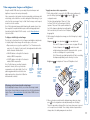
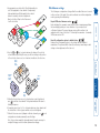
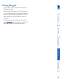
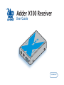
Adder X100 Receiver T O LO C A L PO W ER User Guide TE MO RE R DE ® AD Further information Getting assistance.......................................................................15 Warranty.....................................................................................16 Safety information.....................................................................16 Radio Frequency Energy............................................................17 welcome Connections..................................................................................4 Cable length advice.................................................................4 Connections at the X100 receiver...........................................5 Operation......................................................................................7 General use..............................................................................7 Locking and unlocking the system.........................................7 installation & operation Installation & Operation Configuration...............................................................................8 What are hotkeys?..............................................................8 Entering, using and exiting configuration mode..............8 Password setting......................................................................9 Hot plugging and mouse restoration...................................10 Which restore setting do I use?........................................10 Microsoft and Logitech -specific mouse settings.................10 Video compensation (sharpness and brightness).................11 Skew adjustment...................................................................12 Miscellaneous settings...........................................................13 Performing flash upgrades........................................................14 special configuration Introduction..................................................................................2 Special configuration Welcome contents Contents Welcome PC The local device (AdderView CATx, CAM or other product) connects to the host computer (or KVMA switch). PS/2 MOUSE PS/2 KEYBOARD VIDEO Local device USB welcome The video monitor, mouse, keyboard and speakers* connect to the X100 receiver. X100 Receiver PSU * * X100A or X100AS only, not X100 PS/2 keyboard connection PS/2 mouse connection Video connection Audio connection Brightness control Sharpness control Skew adjustment X100 X100A X100AS This table provides a summary of the abilities of the various X100 receiver models. installation & operation 100 metres or greater separation between the local and remote modules via a single Category 5, or higher, cable. Special circuitry within the X100 receiver allows you to make adjustments to the sharpness and brightness settings to suit your own preferences. Additionally, the X100AS receivers also feature Skew adjustment to counteract the effects of uneven lengths of twisted pair cables that are used to carry the video signals. special configuration and mouse more than 100 metres from a computer system. The range topping X100A and X100AS receivers also allow you to extend your audio accessories away from your computer. Three types of X100 receivers are available to suit your requirements. The long distance link between the originating device and the X100 module is made via Category 5, 5e or 6 twisted pair cabling. Thank you for choosing the Adder X100 receiver. This compact module can be used in conjunction with other Adder products, such as the AdderView CATx, an Adder CAM (Computer Access Module) or other industry leading products. In close harmony with the other Adder device which remains local to the host computer, the X100 receiver allows you to place the controlling keyboard, video monitor contents Introduction contents Supplied items Four self-adhesive rubber feet CD-ROM special configuration Power adapter and countryspecific power lead installation & operation welcome X100 Module Installation & Operation Models X100 and X100A models X100AS Category 5 100m ¹ [100m ¹] 300m ² [200m ²] Category 5e or 6 50 to 100m ¹ [50 to 100m ¹] 300m ² [200m ²] ¹ length limited by skew in the cable. ² length limited by bandwidth compensation amplifiers. In each case the initial values represent maximum distances when using screen resolutions up to 1280 x 1024 @ 60Hz; whereas the [bracketted] values represent distances achievable using resolutions up to 1600 x 1200 @ 60Hz. contents welcome installation & The various X100 receiver models support twisted-pair structured cabling within categories 5, 5e and 6. Of these three cable types, category 5 generally provides the best transmission of video signals because its four pairs of conductors are the most evenly twisted. Category 5e and 6 cables use conductor pairs that are unevenly twisted in order to combat interference effects encountered within higher frequency networks. While these uneven twists work well for Ethernet signals, they can impose problems for the video signals received by the module. The module receives the red, green and blue video signals on separate twisted pairs within the cable. If any of the colour signals are made to travel slightly further or shorter distances than the others, the result is seen as mis-aligned colours on screen. This is called skew and becomes more noticeable as cable runs become longer and screen resolutions/refresh rates increase. X100AS models are equipped with special features to combat the effects of skew - see Skew adjustment. As an approximate guide, you should expect the following maximum cable lengths: special configuration X100 receiver modules offer straightforward installation and generally require minimal configuration. The local device (AdderVeiw CATx, Adder CAM, etc.) connects directly to the computer, while the X100 receiver resides at the other end of the twisted pair cable and attaches to the keyboard, mouse, etc. • Connections at the X100 (remote) module Cable length advice Connections Connections at the X100 receiver R ® 3 Attach the connector of the cable run leading from the local device to the TO LOCAL socket of the X100 receiver. ww d w.a de o r.c m 1 Place the X100 receiver adjacent to the remote user location. 2 Attach the video monitor, keyboard, mouse (and, optionally for X100A and X100AS users, speaker) connectors to the sockets of the Adder X100 receiver. T O LO C A From power adapter 4 (X100A and X100AS models only) Insert the speaker connector to the light green coloured socket situated between the link connector and the power in socket. 5 Insert the output connector of the power supply into the socket at the front edge of the X100 receiver labelled POWER. 6 Insert the IEC connector of the supplied power lead into the corresponding socket of the power supply. Connect the other end of the power lead to a nearby mains socket. 7 Where necessary, use the in-built video compensation feature to eliminate any effects caused by the cable run. See Video compensation for details. welcome From speakers (X100A and X100AS models only) Adder X100 module installation & ER From video monitor Adder X100 module special configuration W From keyboard PO From mouse contents L Category 5, 5e or 6 cable leading to the local device X100 module switches 34 Reserved for future use Determines configuration of hotkeys in conjunction with switch 2 ON 1 2 34 Note: When shipped, all switches are set in the OFF positions and this will produce normal operation. Switches 2 and 3 Switches 2 and 3 determine which two keyboard keys (when pressed in unison) are to be designated as ‘hotkeys’. Hotkeys signal to the X100 receiver that the next key to be pressed is a special configuration command for the module and is not to be passed to the computer system. 2 OFF 3 OFF Hotkeys = CTRL and SHIFT 2 OFF 3 ON Hotkeys = ALT and SHIFT 2 ON 3 OFF Hotkeys = CTRL and ALT 2 ON 3 ON Hotkeys disabled Switch 4 This switch is reserved for future use. welcome 2 installation & 1 special configuration O ON N OFF: Normal operation ON: Flash upgrade Switch 1 OFF: Normal operation. ON: (Before power is applied) Places the X100 receiver into flash upgrade mode so that the internal software can be changed. Please see the Flash upgrade section in the ‘Special configuration’ chapter. Determines configuration of hotkeys in conjunction with switch 3 contents Certain aspects of operation can be affected by the switches on the X100 receiver. Operation To unlock the system . 1 Enter the correct password and press Note: Passwords are NOT case sensitive. Note: If an invalid password has been entered and the keyboard indicators are not flashing as described above, press to clear the incorrect attempt. 2 If the correct password is entered, the screen will be restored and normal operation can continue. To enable the video Simultaneously press the currently configured hotkeys (by default, long with . This command will be required to restore the video if along with is used when no password has been set. To disable the video Simultaneously, press the currently configured hotkeys (by default, along with . and ) and and ) installation & welcome To lock the system 1 First set a password. For further details, please refer to the Password setting section in the ‘Special configuration’ chapter. 2 Simultaneously press the currently configured hotkeys (by default, and ) along with . The screen will go blank and the three keyboard l rol ScLock indicators will begin alternately flashing between the ps CaLock ‘Num Lock’ and ‘Scroll Lock’, and ‘Caps Lock’. This m NuLock sequence indicates that a password is required. contents In situations where the computer system (and the local device) can be locked away, the X100 receiver offers a viable security system to deter unauthorised use. Once a password has been set, a simple key sequence allows the system to be quickly and securely detached from its peripherals. Only the correct password will reconnect the X100 receiver with the local device. special configuration In use, the local device and X100 receiver should be transparent - the system and its peripherals should operate exactly as normal, the only difference being that they are now 100 metres or more apart. In some installations, you may see some ‘shadows’ to the right of high contrast screen characters. This can be caused by an incorrectly selected sharpness setting and it may be necessary to make adjustments to correct this. Please see Video compensation - sharpness and brightness in the ‘Special configuration’ section. Locking and unlocking the system General use Special configuration Hotkeys are two normal keyboard keys that, when pressed simultaneously with a third key, signal to the local device and X100 receiver that you are sending a message specifically to them and not to the computer. The hotkeys are ordinarily and , while a third keypress determines what you want the modules to do. If the standard and hotkeys are also needed for computer tasks, you can change them for another combination using switches 2 and 3 on the X100 receiver: 2 OFF 3 OFF Hotkeys = and (default setting) 2 OFF 3 ON Hotkeys = and 2 ON 3 OFF Hotkeys = and 2 ON 3 ON Hotkeys disabled 2 Press the first letter of the required configuration option, for instance . All three keyboard indicators will illuminate continuously. 3 Press the number of the required configuration option, for instance . The ‘Scroll Lock’ indicator will extinguish, leaving the ‘Num Lock’ and ‘Caps Lock’ indicators lit. contents ps CaLock l rol ScLock welcome To enter and use configuration mode: 1 Simultaneously press the currently configured hotkeys (by default, and ) along with . The three keyboard indicators (‘Num Lock’, ‘Caps Lock’ and ‘Scroll Lock’) will now begin to flash in sequence to show that you are in configuration mode. m NuLock ps CaLock l rol ScLock m NuLock 4 Press to confirm your option. The three keyboard indicators (‘Num Lock’, ‘Caps Lock’ and ‘Scroll Lock’) will now begin to flash in sequence again. To exit from configuration mode: 1 Within configuration mode, the three keyboard indicators should be flashing in sequence to show that the module is ready to receive a new command. 2 Press . The three indicators will return to their normal states. installation & What are hotkeys? Entering, using and exiting configuration mode special configuration You can alter the way that the X100 receiver operates to suit your requirements. This is done using the Configuration mode and you can affect the following settings: • Password setting – allows you to lock the remote module to prevent unauthorised system access. • Mouse restoration and settings – allows you to restore mouse operation and also to change the mouse type. • Video compensation - sharpness & brightness – allows you to manually adjust the video image to ensure that it is crisp and bright. • Skew adjustment (X100AS only) – allows you to manually compensate for possible video errors introduced by long, uneven cable connections. • Miscellaneous settings – report firmware version and restore settings. Configuration Password setting welcome installation & special configuration To set a password and ) along with 1 Simultaneously, press the hotkeys (by default, to enter configuration mode. 2 Press followed by . 3 Now enter your new password, within the following constraints: • Passwords are NOT case sensitive, • Passwords may be any length from one character to a maximum of forty characters, • The following keys may NOT be used: , , , or 4 When you have entered the password, press to signal its completion. 5 Press once more to exit configuration mode. For full details about how to lock and unlock the system using your password, please see the Locking and unlocking the system section in the ‘Installation and operation’ chapter. contents Password protection allows you restrict access to the system only to authorised personnel. A password first needs to be set and then, using the keyboard attached to the X100 receiver, a simple key sequence allows the system to be quickly and securely detached from its peripherals. Recognising an Intellimouse-style mouse The Intellimouse format was introduced to support, among other features, the scroll wheel function. If your mouse has a scroll wheel, then it is likely to support the Intellimouse format. If you have a Microsoft mouse, then it will usually state that it is an Intellimouse on its underside label. Recognising an Intellimouse driver Before hot plugging (or afterwards using only keyboard control), access the Windows Control Panel and select either the Mouse option (on Windows NT, 2000 and XP) or the System option (on Windows 95, 98, ME). Look for the name of the driver, which will usually include the words PS/2 or Intellimouse. Microsoft and Logitech -specific mouse settings welcome In certain installations some Logitech mouse drivers may lose the action of the mouse buttons when used with the standard ‘Microsoft compatible’ signalling protocol used between the modules. To solve this problem, select the ‘Logitech compatible’ mouse signalling protocol. installation & The general rule is that unless both the mouse and the driver are both Intellimouse compatible then you need to restore the mouse as ‘PS/2’. To change mouse signalling protocols 1 Simultaneously, press the hotkeys (by default, to enter configuration mode. 2 Enter the appropriate protocol code: • Microsoft compatible – press • Logitech compatible – press special configuration Which restore setting do I use? To restore mouse operation when hot plugging: 1 Carefully connect the local device and the X100 receiver to the system and its keyboard, mouse, monitor and speakers. and ) along with 2 Simultaneously, press the hotkeys (by default, to enter configuration mode. 3 Enter the appropriate restore function code: • PS/2 – press • IntelliMouse – press 4 To exit configuration mode, press . 5 Move the mouse a short distance and check for appropriate on-screen cursor movement. If the mouse cursor darts erratically around the screen, then cease moving the mouse. This is an indication that the chosen restore function is incorrect. Try again using the other restore function. Note: The restore functions predict the likely mouse resolution settings but may not restore the exact speed or sensitivity settings that were originally set. 3 To exit configuration mode, press and ) along with . It is strongly recommended that you switch off the computer system before attempting to connect the local device and X100 receiver. However, if this is not possible then you need to ‘hot plug’ the local device and X100 receiver while power is still applied to the system. There is not normally a danger of damage to the system, however, when mouse communications are interrupted, often they fail to reinitialise when reconnected. The X100 receiver provides a feature to reinstate mouse communications once the necessary connections have been made. There are two main types of data formats used by current PC mice, these are the older ‘PS/2’ format and the more recent ‘IntelliMouse® ’ format introduced by Microsoft. These use slightly different data arrangements and it is important to know which type was being used before you hot-plugged the local device and X100 receiver. The previous setting depends both on the type of mouse and the type of driver as various combinations of PS/2 and Intellimouse are possible. Using the incorrect restore function may produce unpredictable results and require the system to be rebooted. contents Hot plugging and mouse restoration 10 If the image controls cannot provide a crisp image If, after adjusting the image controls, one or more screen images remain fuzzy or have coloured shadows you may need to use the Skew adjustment feature. Please see Skew adjustment for details (Adder X100AS receiver only). for adjustment. There are 255 brightness levels. Sharpness increase (coarse) Restore default sharpness and brightness settings Sharpness decrease (coarse) Sharpness increase (fine) Exit image controls and save settings Brightness decrease Brightness increase Sharpness decrease (fine) 3 When no shadows are visible and the displayed images have crisp edges, press to exit configuration mode and permanently save all settings. The new compensation settings will be stored, even when power is removed or if a complete reset is initiated. These settings should not require further changes unless the cabling arrangements are altered. welcome installation & Brightness: special configuration To display a suitable high contrast image The best way to clearly view the effect of sharpness and brightness adjustments is to display a high contrast image, with vertical edges, on the screen. • Open a word processor, type the capital letter ‘H’, or ‘M’ and increase the point size to 72 or higher. For best results, the background should be white and the character should be black. • A black shadow on the right of the character indicates under compensation. • A white shadow on the right of the character indicates over compensation. Note: The Word processor method is accurate and quick. However, for the very finest video High contrast Black or bright compensation, use the latest Adder “skew” test black character white shadow on white on the right pattern program which shows both the skew background indicates the need for pattern and a section of mixed size Hs (black on sharpness white and white on black). adjustment To apply remote user video compensation 1 On the keyboard that is connected to the X100 receiver, simultaneously, press the hotkeys (by default, and ) along with to enter configuration mode. The three keyboard indicators (‘Num Lock’, ‘Caps Lock’ and ‘Scroll Lock’) will now begin to flash in sequence. The speed of the sequence indicates the level of the sharpness adjustment currently applied: the slower the rate, the lower the level of sharpness being applied. 2 While viewing the displayed screen image, use the following keys to adjust the controls: Sharpness: for fine adjustment, for coarse adjustment. There are 255 sharpness levels (one coarse step jumps 10 levels). To autoset sharpness: Press to make the module calculate and apply an automatic compensation level - you can use this as a starting point for your fine tuning. Note: If the monitor goes blank and switches off (due to oversetting the sharpness adjustment) press the Home key to restore. Using the in-built X100 controls you can adjust the picture sharpness and brightness to improve the remote picture quality. Video compensation is best carried out when viewing high contrast images with vertical edges, such as black lines on a white background. When doing so, if you notice that the screen image is ‘fuzzy’ or ‘dark’ then the image controls may not be able to solve this condition. Note: If the high contrast images exhibit shadows with separate colours, then there may be a skew problem which requires a different image adjustment (provided only by the Adder X100AS receiver) - see the Skew adjustment section for details. contents Video compensation (sharpness and brightness) 11 Skew adjustment 2 On the remote user keyboard (connected to an Adder X100AS receiver), simultaneously, press the hotkeys (by default, and ) along with enter configuration mode. The three keyboard indicators (‘Num Lock’, ‘Caps Lock’ and ‘Scroll Lock’) will now begin to flash in sequence. welcome special configuration Creating a skew test pattern i Run any image creation/editing application, such as the Paint program supplied with Windows. ii Using the image application create three stacked horizontal rectangles (one red, one green and one blue) that fill the width of the screen. iiiDraw a vertical black line down across the coloured bars and then repeat this vertical line at intervals along the width of the coloured bars. These lines create breaks across the colours and give you more opportunities to view the horizontal position of each colour relative to the others. installation & Using the supplied skew pattern i Insert the supplied Adder Installation CD-ROM into the CD player of the computer. ii Within Windows, use the My Computer option (usually available as a desktop icon or within the Start menu) to view the contents of the CD-ROM. Double-click the Skew entry to display the standard Convergence test test pattern. If necessary, maximise the pattern showing the RGB crosses. In this application window so that the image fills case, the green signal can be seen out of the screen. line with the other two colours. The screen will show a series of fine red, green and blue crosses which should all be in line, vertically and horizontally. Skew affects the horizontal placement of the colours and using this pattern it is much easier to discover which, if any, colours are being adversely affected by the cable link. contents To use skew adjustment 1Display a skew pattern on the appropriate computer. You can either use the supplied skew pattern or create your own: to The category 5, 5e and 6 cabling supported by the X100 receiver consists of four pairs of wires per cable. Three of these pairs are used to convey red, green and blue video signals to the remote video monitor. Due to the slight difference in twist rate between these three pairs, the 12345678 red, green and blue video signals may not arrive at precisely the same time. This is visible as separate colour shadows on high contrast screen images and is particularly apparent when using higher screen resolutions and some types of category 5e and 6 cables. 8 8 Data signal 7 7 To alleviate this situation, the Adder 6 6 Red X100AS receiver provides internal skew 3 3 video signal adjustment that can help to rectify the 5 5 Green situation. The skew adjustment works by 4 4 video signal delaying or advancing the timing of any 2 2 Blue 1 of the red, green or blue colour signals so 1 video signal that they are all delivered to the monitor at precisely the same time. For best results, the “skew” program supplied on the disk or downloadable from www.adder.com or www.adder.info is the most accurate way of setting skew as the red, green and blue lines are rendered exactly on the screen as single pixel wide lines. The skew.bmp test pattern can also be used but it is less accurate. Alternatively, you can create your own skew pattern using a standard image creation package, as detailed opposite. 12 Miscellaneous settings NuLock ps CaLock l rol ScLock m NuLock ps CaLock l rol ScLock m NuLock 4 Press the and keys to retard or advance the timing of the selected colour channel respectively. On screen you will see a change in the position of the selected colour crosses (or colour bars) in relation to the other two. Reset all configuration options to default states - Returns all user configurable options to the settings that are installed at manufacture. The password will be cleared, however, any current image control settings or skew adjustments will not be reset. Advance colour timing Retard colour timing 5 When the selected colour crosses (or colour bars) are correctly positioned, press to exit that colour channel. The keyboard indicators will return to flashing in sequence. 6 If required, repeat steps 3 to 5 to select and adjust any colour channel until the vertical lines of the red, green and blue crosses are all aligned. 7 When all colours are correctly aligned on all video channels, press to exit configuration mode and permanently save all settings. Note: Once you have made the skew adjustments, it may be necessary to re-adjust the image controls to attain optimum screen images. Exit image controls and save settings special configuration installation & Restore default skew settings Report X100-series firmware version Before initiating this command, ensure that the system is running an application that can display typed keys as screen characters - e.g. a word processor or Windows Notepad. The current firmware version will be written to the application in the form of the letter ‘V’ followed by three numbers - for example V201 means version 2.01. contents ps CaLock l rol ScLock The following are configuration settings within the modules that are not covered in other sections of this guide. These can be achieved once within configuration mode by pressing the indicated keys: welcome 3 As appropriate, press either the R, G or B keyboard keys to select the appropriate colour channel. Corresponding keyboard indicators will flash rapidly to show which channel is currently selected for adjustment: Num Lock for Red, Caps Lock for Green and Scroll Lock for Blue. m 13 welcome installation & special configuration The Adder X100 receiver is fully reconfigurable via flash upgrades using the KVM Firmware Uploader utility. During the upgrade you will be required to connect the X100 receiver directly to a computer system using a special cable. The upgrade utility will update the firmware of the X100 receiver and also temporarily transform it so that it can update the CAM unit. Once completed, the X100 receiver will return to its normal operation. The KVM Firmware Uploader utility is available from the Adder Technology website (www.adder.com) and allows you to check the current revision of the X100 firmware. Full instructions are provided with the download file. contents Performing flash upgrades 14 Further information • Adder Technology website – www.adder.com Check the Support section of our website for the latest solutions and driver files. contents Getting assistance • Phone in the UK: in the US: 01954 780044 +1 888 932 3337 installation & 01954 780081 +1 888 275 1117 special configuration in the UK: in the US: further information • Fax welcome • Email – [email protected] 15 contents welcome installation & • For use in dry, oil free indoor environments only. •Do not use to link between buildings. • Ensure that all twisted pair interconnect cables are installed in compliance with all applicable wiring regulations. •Do not connect CATx link interfaces (RJ45 style connectors) to any other equipment, particularly network or telecommunications equipment. • Warning – the power adapter contains live parts. • No user serviceable parts are contained within the power adapter - do not dismantle. • Plug the power adapter into a socket outlet close to the X100 module that it is powering. • Replace the power adapter with a manufacturer approved type only. •Do not use the power adapter if the power adapter case becomes damaged, cracked or broken or if you suspect that it is not operating properly. • If you use a power extension cord with the X100 module, make sure the total ampere rating of the devices plugged into the extension cord do not exceed the cord’s ampere rating. Also, make sure that the total ampere rating of all the devices plugged into the wall outlet does not exceed the wall outlet’s ampere rating. •Do not attempt to service the modules yourself. • The X100 module and power supply can get warm in operation – do not situate them in an enclosed space without any ventilation. • The X100 module does not provide ground isolation and should not be used for any applications that require ground isolation or galvanic isolation. special configuration Adder Technology Ltd warrants that this product shall be free from defects in workmanship and materials for a period of two years from the date of original purchase. If the product should fail to operate correctly in normal use during the warranty period, Adder will replace or repair it free of charge. No liability can be accepted for damage due to misuse or circumstances outside Adder’s control. Also Adder will not be responsible for any loss, damage or injury arising directly or indirectly from the use of this product. Adder’s total liability under the terms of this warranty shall in all circumstances be limited to the replacement value of this product. If any difficulty is experienced in the installation or use of this product that you are unable to resolve, please contact your supplier. Safety information further information Warranty 16 Canadian Department of Communications RFI statement This equipment does not exceed the class A limits for radio noise emissions from digital apparatus set out in the radio interference regulations of the Canadian Department of Communications. Le présent appareil numérique n’émet pas de bruits radioélectriques dépassant les limites applicables aux appareils numériques de la classe A prescrites dans le règlement sur le brouillage radioélectriques publié par le ministère des Communications du Canada. welcome This equipment generates, uses and can radiate radio frequency energy and if not installed and used properly, that is, in strict accordance with the manufacturer’s instructions, may cause interference to radio communication. It has been tested and found to comply with the limits for a class A computing device in accordance with the specifications in Subpart J of part 15 of FCC rules, which are designed to provide reasonable protection against such interference when the equipment is operated in a commercial environment. Operation of this equipment in a residential area may cause interference, in which case the user at his own expense will be required to take whatever measures may be necessary to correct the interference. Changes or modifications not expressly approved by the manufacturer could void the user’s authority to operate the equipment. installation & This equipment has been tested and found to comply with the limits for a class A computing device in accordance with the specifications in the European standard EN55022. These limits are designed to provide reasonable protection against harmful interference. This equipment generates, uses and can radiate radio frequency energy and if not installed and used in accordance with the instructions may cause harmful interference to radio or television reception. However, there is no guarantee that harmful interference will not occur in a particular installation. If this equipment does cause interference to radio or television reception, which can be determined by turning the equipment on and off, the user is encouraged to correct the interference with one or more of the following measures: (a) Reorient or relocate the receiving antenna. (b) Increase the separation between the equipment and the receiver. (c) Connect the equipment to an outlet on a circuit different from that to which the receiver is connected. (d) Consult the supplier or an experienced radio/TV technician for help. FCC Compliance Statement (United States) special configuration European EMC directive 89/336/EEC further information A Category 5 (or better) twisted pair cable must be used to connect the units in order to maintain compliance with radio frequency energy emission regulations and ensure a suitably high level of immunity to electromagnetic disturbances. All other interface cables used with this equipment must be shielded in order to maintain compliance with radio frequency energy emission regulations and ensure a suitably high level of immunity to electromagnetic disturbances. contents Radio Frequency Energy 17 contents installation & special configuration Adder Corporation, 29 Water Street, Newburyport, MA 01950, United States of America Tel: +1-888-932-3337 Fax: +1-888-275-1117 further information Adder Technology Limited, Technology House, Trafalgar Way, Bar Hill, Cambridge, CB3 8SQ, United Kingdom Tel: +44 (0)1954 780044 Fax: +44 (0)1954 780081 welcome © 2006 Adder Technology Limited All trademarks are acknowledged. Release 1.0b December 2006 Part No. ADD0068 Documentation by: www.ctxd.com 18