1
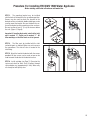
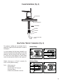
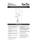
™
™
Owner's Manual
This Manual is for the Installation, Operation,
and Maintenance of the
™
WATER FACTORY SYSTEMS
™
Faucet MATE FM DWS 1500
Drinking Water Appliance
98-91122 1009
Installer: Leave with Homeowner.
Introduction
This manual explains the installation and maintenance instructions for the CUNO/Water Factory Systems™ FaucetMATE™
FM DWS 1500. Please read each section of this manual carefully. The specific model chosen should be appropriate for the
local water conditions and the customer’s needs. Check the Performance Data Sheet which specifies performance
characteristics and the conditions of use.
This CUNO/Water Factory Systems drinking water appliance is designed to connect permanently to a home plumbing system.
To ensure the installation conforms to your state and local plumbing codes, it is recommended that the installation be
performed by a qualified specialist for drinking water appliances or a licensed plumber. Failure to install as instructed will
VOID the warranty.
Table Of Contents
Installation Instructions
Installation Precautions ..............................................................................................................................3
Determine System Location .......................................................................................................................3
Prepare The Area For Installation ...............................................................................................................3
Prepare The Appliance For Installation .......................................................................................................4
Locating The Faucet ...................................................................................................................................4
Make The Faucet Mounting Hole ................................................................................................................4
Mounting The Faucet ..................................................................................................................................5
Mounting The Drinking Water Filtration Appliance .....................................................................................5
Installing The Feed Water Valve/Adapter ....................................................................................................5
Make Tubing Connections ..........................................................................................................................5
Procedure For Installing FM DWS 1500 Water Appliance ..........................................................................6
Replacement Cartridge Change Instructions ..............................................................................................7
Illustrations
System Location (Figure 1) ........................................................................................................................8
Faucet Installation (Figure 2) ......................................................................................................................9
How To Use ‘Push-In’ Connections (Figure 3) ...........................................................................................9
2
Installation Precautions
• The filter must be installed with the inlet and outlet ports
as labeled. Make sure not to reverse connections.
Procedure for Installing
FM DWS 1500
A. Determine System Location
• Do not install on hot water line. Maximum
temperature allowed is 100°F (38°C).
• Do not install on line pressure above 125 psi
(862 kPa).
• Do not use torch or other high temperature
sources near filter head or plastic cartridge.
• Do not install near electric wires or water pipes which
will be in path of drill when selecting the position to
mount the bracket.
• Do not install in direct sunlight.
• Protect from freezing. Drain filter when room temperature
drops below 40°F (4.4°C).
• Allow minimum of 2" (5 cm) clear space under filter to
facilitate cartridge change.
• Mount filter in such a position as to prevent it from being
struck by other items, such as wastebaskets, etc.
• Do not use with water that is microbiologically unsafe or
of unknown quality without adequate disinfection before
or after the system. Systems certified for cyst reduction
may be used on disinfected waters that may contain
filterable cysts.
The filtration system can be located under a sink. Never
install in an area of the home where the temperature may
drop to freezing as damage to the system will result.
The exact placement of the various components of the
appliance will vary from installation to installation. The
installer, in conjunction with the customer, must decide on
where to place the faucet and filtration system by balancing
the homeowners convenience with ease of installation and
servicing. (See Fig. 1)
B. Prepare The Area For Installation
Remove supplies from under the sink and stack them neatly
away from the working area. Arrange a light for the work area,
if necessary. If a basement installation is called for, determine
where components will be located and how they will be
mounted. Special mounting brackets and hardware may be
necessary to secure the system to a wall or ceiling joints.
Inspect cold water supply line to determine if any special
fittings, in addition to what is included in the kit, are
required.
NOTE: It is a good idea at this time to check the condition
of the customer’s undercounter plumbing for any existing
or potential leaks. The customer should be advised of any
problem so there is no misunderstanding of who is
responsible.
• System installation must comply with existing
state or local plumbing codes.
• IMPORTANT: Some local plumbing codes may prohibit
the use of saddle-type valves and/or drain connections.
The use of saddle-type valves are prohibited in Alaska,
Delaware, Idaho, Kentucky, Massachusetts, Michigan,
Minnesota, New Hampshire, Ohio, and South Dakota.
Check your local plumbing codes for any restrictions
that apply. Massachusetts CMR 248 strictly prohibits the
use ofsaddle-type valves. The feed water connection
must conform to applicable plumbing codes.
3
C. Prepare The Appliance For Installation
D) Clean up sharp edges with a file if necessary.
Open shipping carton and remove components. Check that
all installation parts are present which includes the filter
assembly, faucet, installation hardware and tubing.
D. Locating The Faucet
Select a sink or countertop location at least two inches in
diameter on which to mount the drinking water faucet. The
faucet should be positioned so that it empties into the sink.
Make sure the location directly underneath this area is free
of obstruction in order to accommodate the faucet assembly.
If the sink already has a hole provided that can accommodate
the faucet, then no drilling is required and you can proceed
to the section on mounting the faucet. (See Fig. 2)
E. Make The Faucet Mounting Hole
IMPORTANT: It is mandatory that safety glasses be worn
during sink hole drilling operations to prevent eye
injury.
IMPORTANT: Extreme care must be taken when drilling
the hole for the faucet. The surface material is hard and
brittle and easily chipped or cracked. The manufacturer
assumes no responsibility for sink damage resulting from
this installation.
A wide variety of faucet mounting situations may be
encountered, the most common being stainless steel and
ceramic-on-metal sinks. Consult a plumber for the other
materials that may be encountered.
Before starting the hole making operation, always check
below the sink so that nothing interferes with mounting the
faucet such as reinforcing ribs, support brackets or cabinet
construction.
Stainless Steel Sink
Recommended tools:
• Center punch
• Variable speed drill and high speed drill bits
• Chassis punch 9/16” size
• Protective Gloves
Procedure:
A) Center punch a small indent at the desired faucet
location.
Porcelain/Enamel/Ceramic
on sheet metal or cast iron base:
Recommended Tools:
• Variable speed drill
• Porcelain cutter tool set 9/16” size
• Plumber’s putty
It is important to understand what is involved in this
procedure. First, the glassy layer of porcelain must be
penetrated through to the base metal. Second, a center disc
of porcelain must be removed while protecting the
surrounding porcelain against chipping or fracturing. Third,
the base metal must be drilled through to complete the
hole.
IMPORTANT: When using a porcelain cutter it is critical to
take precautions that it is always in a sharpened condition.
Dull cutters are known to chip sinks.
Procedure:
A) Mark the center for the 9/16” hole.
B) Form shallow putty dam around hole area and fill
with enough water to lubricate carbide drill bit.
C) Carefully drill pilot hole through porcelain/enamel
and base metal using carbide type pilot drill.
IMPORTANT: Always operate drill with light
pressure at slow speed (300-400 rpm).
D) Insert pilot tip of spring loaded porcelain cutter into
pilot hole.
E) Drill porcelain/enamel using spring-loaded porcelain
cutter, making certain a complete ring has been cut
through the porcelain/enamel to the metal base.
F) Change to the metal cutter. With slow speed and light
pressure, cut away the inner porcelain/ enamel disc
down to base metal. Make certain that the cutter does
not touch outer rim of the cut porcelain/enamel.
Continue with this bit to cut through metal until sink
has been completely penetrated.
B) Slowly drill required pilot hole for the chassis punch.
C) Set up the chassis punch per instructions and tighten
nut to cut the desired hole size.
4
F. Mounting The Faucet
H. Installing The Feed Water Valve/Adapter
1. Remove all hardware from the threaded nipple of the
faucet except for the plastic base plate. Use a small
amount of putty to seal the base plate.
Due to variations in plumbing types and due to various
State and Local plumbing codes, this product does not
include a feed water adapter/valve. Please obtain the
appropriate code compliant adapter/valve from the
retailer where this product was purchased.
2. Put the blue tubing and threaded nipple through the
faucet mounting hole and position the faucet spout
over the sink.
3. From below sink/countertop, assemble the plastic
bottom washer, star washer and hex nut onto the
threaded nipple and tighten by hand. (See Fig. 2).
4. After rechecking faucet orientation, tighten hex nut with
a 9/16” wrench until faucet feels secure.
5. From above the sink, make any minor orientation
corrections by turning the faucet on its “flats” with a
padded adjustable wrench. Use care so as not to mar
the stainless steel finish.
I. Make Tubing Connections
NOTE: With all the components in place, the tubing
connections can be made. Be sure to arrange the tubing so
that there are no sharp bends. Leave some “play” in the
tubing for ease of servicing. (Figure 3)
NOTE: Try to keep the tubing from filtration system to the
faucet as short as possible to ensure good water flow.
1. Connect one end of the 1/4” orange tubing to the
“Push-In” male connector on the ball valve located on
the inlet side of the filtration assembly. (Refer to Fig. 3
on the use of “Push-In” plastic fittings.) Connect the
other end to the feedwater valve (not included).
G. Mounting The Drinking Water Filtration System
NOTE: Be sure to locate the system where there is a
minimum of 2” clearance underneath it to facilitate filter
cartridge changes.
2. Connect the 1/4” blue tubing from the faucet to the
“Push-In” fitting attached to the outlet connection on
the filtration assembly.
1. Mark the mounting screws location on the cabinet
side wall using the holes on the bracket as guides.
2. Drill starter holes into side wall.
3. Hang the filtration system onto the side wall by
fastening wood screws through the bracket and
into the mounting surface.
5
Procedure For Installing FM DWS 1500 Water Appliance
Before starting, close shut-off valve on cold water line.
STEP 1: The mounting bracket may be installed
with the back of the bracket in the up or down position.
Screws may be used to attach the bracket to the
desired surface or industrial double-sided tape can be
used to mount the bracket. Be sure that both the surface of the bracket and the mounting surface are clean.
Be sure to allow at least 2" (5 cm) of clearance below
the unit. (Figure 1, Page 8)
1
2
3
4
Important: If inverting the bracket, note that the inlet
port is marked “3”. Outlet port is marked “1”. All
other markings on the filter head are to be ignored.
STEP 2: The filter must be installed with the inlet
and outlet ports as labeled. Make sure not to reverse
the connections. The shut-off valve is located in the
inlet fitting.
STEP 3: Attach the head to the bracket with the screws
provided. All four screws can be used, or two can be
used to mount the bracket to the desired surface.
STEP 4: Install cartridge (see Page 7). Pressurize the
system and check for leaks. Flush 3 gallons through
system before use (approximately 6 min). Water may
run cloudy but will quickly clear.
6
Replacement Cartridge Change Instructions
FM DWS 1500
Turn Clockwise To
Shut Off
1. Close the feed water valve and lift up the faucet handle.
Wait approximately 10 seconds for the water pressure
to depressurize. Return faucet handle to the off
position.
2. Twist the filter cartridge 1/4 turn counterclockwise (as
viewed from the bottom) so that the ears on the
cartridge are able to disengage from the head. Firmly
pull the cartridge downward to remove it from the
head.
3. Remove the new filter cartridge from its sanitary sealed
wrapper. (Double check to see that it is the correct
replacement filter cartridge by comparing the labels.)
Turn Counterclockwise
To Turn On
5. Line up the cartridge ears, insert the cartridge and push
it up into the head until it is fully seated. Twist the
cartridge 1/4 turn clockwise to lock it into place.
6. Open the feed water valve and carefully check for
leaks.
7. Lift up on faucet handle to purge air and carbon fines
from the new filter cartridge. Flush 3 gallons through
system before use (approximately 6 min).
NOTE: It is normal to have small air bubbles present in the
product water for 1-2 days after installation and filter
changes. This may result in cloudy filtered water.
4. Using either tap water, food grade silicon lubricant or
glycerine, lubricate the O-ring seals to make cartridge
insertion easier. Do not use petroleum jelly.
It is recommended that cartridges be replaced every 6-12 months, depending on local water conditions and use.
7
System Location (Fig.1)
Allow 2” Min.
Clearance
To Faucet
Outlet Fitting w/
Flow Control
Ball Valve
From Feedwater Source
8
Faucet Installation (Fig. 2)
Plastic Base Plate
Plastic Bottom Washer
Threaded Nipple
Flat Washer
Star Washer
Hex Nut
Blue 1/4” Product Water
Tubing
How To Use ‘Push-In’ Connectors (Fig. 3)
This product is outfitted with user-friendly ‘Push-In’
connectors. Proper use of the connectors is shown in
the diagrams.
It is most important that the tubing selected for use
with these connectors be of high quality, exact size and
roundness, and free of surface nicks and scratches. If
it is necessary to cut the tubing, use a plastic tubing
cutter or sharp razor knife. Make it a clean square cut.
To Attach Tubing
1
Tube
2
Grey Collet
Push tubing straight in as far as it will go. Tubing is secured in.
Should a leak occur at a ‘Push-In’ connector, the
cause is usually defective tubing.
To Release Tubing
1
2
Push in grey collet to release tubing.
Pull tubing straight out.
To fix: • Relieve pressure
• Release tubing
• Cut off at least 1/4” from end
• Re-attach tubing
• Confirm the connection is leak free
9
CUNO Incorporated
CUNO, Faucet Mate and Water Factory Systems are
trademarks of 3M Company used under license.
© 2009 3M Company. All rights reserved.
400 Research Parkway
Meriden, CT 06450, U.S.A.
Toll Free: 1-800-733-1199
Worldwide: 203-237-5541
Fax: 203-238-8701
www.waterfactorysystems.com • www.cuno.com