1
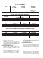
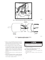
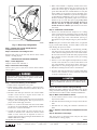
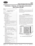
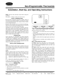
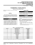
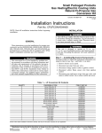
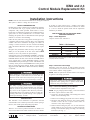
ICM2 and 2.3
Control Module Replacement Kit
Cancels: IIK 333B-60-1
IIK 333B-60-2
9-01
Installation Instructions
NOTE: Read the entire instruction manual before starting the installation.
This symbol → indicates a change since the last issue.
SAFETY CONSIDERATIONS
Installing and servicing of heating and air conditioning equipment
can be hazardous due to gas, system pressures and electrical
components. Only trained personnel should install or service
heating and air conditioning equipment. The qualified installer or
agency must use factory authorized kits or accessories when
modifying this product. Refer to individual instructions packaged
with kits or accessories when installing.
Follow all safety codes. Wear safety glasses and work gloves. Use
a quenching cloth for brazing operations. Have a fire extinguisher
available. Read these instructions thoroughly and follow all
warning or cautions attached to the unit. Consult local building
codes and National Electrical Code (NEC) for special requirements.
Recognize safety information. This is the safety-alert symbol
.
When you see this symbol on the unit and in instructions or
manuals, be alert to the potential for personal injury.
Understand the signal word DANGER, WARNING, CAUTION,
and NOTE. These words are used with the safety-alert symbol.
DANGER identifies the most serious hazards which will result in
severe personal injury or death. WARNING signifies a hazard
which could result in personal injury or death. CAUTION is used
to identify unsafe practices which would result in minor personal
injury or product and property damage. NOTE is used to highlight
suggestions which will result in enhanced installation, reliability,
or operation.
Before installing or servicing unit, always turn off all gas and
electrical supplies to unit. There may be more than one
disconnect switch. Turn off accessory heater power if applicable. Electrical shock can cause personal injury or death.
The ability to properly perform service on this equipment
requires certain expertise, mechanical skills, tools, and equipment. If you do not possess these, do not attempt to perform
any service on this equipment other than those procedures
recommended in the User’s Manual. A failure to follow this
warning could result in possible damage to this equipment,
serious personal injury, or death.
INTRODUCTION
This instruction covers installation of replacement electronic
control modules on all variable speed fan coils, variable speed gas
furnaces, and variable speed small packaged products.
DESCRIPTION AND USAGE
This kit is to be used for products which have an ICM2 or 2.3
motor with a round control module attached to the motor end bell.
If servicing an earlier vintage motor, a complete motor which
includes this module must be used instead of this kit. See Tables
2, 3, and 4 to match the product model with the replacement
module kit part number.
INSTALLATION FOR FAN COILS AND SMALL
PACKAGED PRODUCTS
Step 1—Check Equipment
Compare contents of kit with Table 1.
Table 1—Kit Contents
PART NO.
See Tables 2, 3, 4
111A522AAP7
A-8794728AYP1
HY76TB121
DESCRIPTION
Electronic Control Module
3 1/2–in.
1/4 Hex Bolts
Plastic Locator Pin
Wire Tie
QUANTITY
1
2
1
1
* Replacement control modules are factory programmed for specific products
and model sizes. Even though they look alike, different modules will have
completely different functionality.
Step 2—Disconnect Line Voltage
Disconnect power from fan coil or small packaged unit being
serviced. There may be more than one disconnect switch. Do not
work on motor with line voltage applied.
NOTE: Failure of replacement controller will also occur if power
is applied to unit during replacement.
Wait at least 5 minutes after disconnecting line voltage from
equipment before opening motor to prevent electric shock
which can cause personal injury or death.
Step 3—Disconnect Existing Control Module
1. Remove blower compartment access panel.
NOTE: For gas packaged products unplug 3 wires from induced
draft motor capacitor and move them aside.
2. If necessary, clip wire tie holding wires running from control
module to motor mounting arms.
3. Remove screw holding green ground wire to blower housing.
4. Disconnect both multi-pin connectors from control module
attached to motor. Be sure to depress release latches on
connectors or they may be damaged.
5. Remove blower housing and place it on its side with motor
control module up. It is not necessary to remove motor from
housing. Control module unplugs according to the following
instructions. (See Fig. 1.)
Manufacturer reserves the right to discontinue, or change at any time, specifications or designs without notice and without incurring obligations.
Book 1 1 4 4
PC 101
Catalog No. 534-015
Printed in U.S.A.
Form 40FK-6SI
Pg 1
9-01
Replaces: 40FK-2SI
Tab 3d 6a 2e 8a
Table 2—Fan Coil Replacement Control Module Part Numbers
(FK4, FV4, 40FKA, PF1MNA071)
MOTOR
HORSE POWER
1/2 HP
3/4 HP
REPLACEMENT
MODULE
PART NUMBER
RMOD44AE131
RMOD44AE132
RMOD44AE133
CURRENT
REPLACEMENT
MOTOR NUMBER
HD44AE131
HD44AE132
HD44AE133
RMOD46AE244
HD46AE244
PREVIOUS
REPLACEMENT
MOTOR NUMBERS
HD44AE125, 122, 118, 128
HD44AE127, 124, 119, 129
HD44AE126, 123, 130
HD46AE240, 242, 241
HD52AE118, 243
Table 3—Furnace Replacement Control Module Part Numbers
(333BAV, 333JAV, 355MAV, 58MVP, 58UXV, 58UAV)
MOTOR
HORSE POWER
1/2 HP
3/4 HP
1HP
1/2 HP
3/4 HP
1HP
1/2 HP
1HP
REPLACEMENT
CURRENT
MODULE
REPLACEMENT
PART NUMBER
MOTOR NUMBER
Non-Condensing Furnaces
RMOD44AE120, 121
HD44AE120, 121
RMOD46AE120
HD46AE120
RMOD52AE121
HD52AE121
Condensing Furnaces
RMOD44AE116
HD44AE116
RMOD46AE121
HD46AE121
RMOD52AE120
HD52AE120
Condensing Downflow Furnaces
RMOD44AE117
HD44AE117
RMOD52AE117
HD52AE117
PREVIOUS
REPLACEMENT
MOTOR NUMBERS
HD44AE120, 121
HD46AE120
HD52AE121
HD44AE116
HD46AE121
HD52AE120, 116
HD44AE117
HD52AE117
Table 4—Light Commercial Blower Motor Replacement Control Module Part Numbers
(48GP-, 50GL-, 50JZ-, 48SX-, 48HX-, 50SX-, 50HX048-060; 583B-, 702B-, 602B-, 557ANX-, 589ANW-, 658ANW048060, 657ANX048, 657APX060
MOTOR HORSE
POWER
1 HP
1/2 HP
3/4 HP
3/4 HP
1 HP
REPLACEMENT
MODULE
PART NUMBER
RMOD52AE123
RMOD44AE134
RMOD46AE134
RMOD46AE245
RMOD52AE134
CURRENT
REPLACEMENT
MOTOR NUMBER
HD52AE123
HD44AE134
HD46AE134
HD46AE245
HD52AE134
PREVIOUS
REPLACEMENT
MOTOR NUMBERS
HD52AE119
New
New
New
New
2. If any motor fails these tests, do not install control module.
The motor is defective and must be replaced. Installing
new control module will cause it to fail also. Spin wheel to
be sure motor turns freely.
Step 5—Install New Control Module
6. Remove two 1/4-in. hex head bolts from old control module
and discard. DO NOT REMOVE TORX HEAD SCREWS
located next to 1/4-in. hex head bolts.
7. Carefully lift control module off motor. Depress latch on
connector to disconnect wire connector that attaches control
module to motor. Latch must be depressed to remove or
connector and/or motor may be damaged. DO NOT PULL ON
WIRES. GRIP PLUG ONLY.
→ Step 4—Motor Check-Out Procedure
1. Remove new controller from box and place it on a working
surface with all electrical components facing up. Find plastic
locator pin (in bag of fasteners included with kit). Locate deep
slot along upper edge of new control module. (See Fig. 2.)
Slide plastic locator pin with pin facing away from control into
slot.
NOTE: This pin is needed on older ICM2 motors, recognizable
by gray control module housing. On newer ICM2.3 motors with
the black housing this pin is not needed.
1. When control module is completely detached from motor,
verify with standard ohmmeter that the resistance from each
motor lead in motor plug to unpainted motor end plate is
greater than 100k ohms. Use standard ohmmeter to verify that
motor windings are not shorted or open by measuring resistance between each combination of pins in motor plug (there
are 3 different combinations, pin 1-2, pin 2-3, and pin 1-3).
Resistance should be approximately equal across each combination of any two of the three pins in plug.
2
2. Position new control module over motor/housing assembly
such that locator pin is aligned with mating hole on motor.
Attach connector coming from motor to new control module.
Be sure connector latches. It will click when properly inserted.
Place controller on motor with plastic locator pin in mating
hole on motor.
A98537
Fig. 1—Disconnecting Control Module from Blower Motor
MULTI-PIN
CONNECTOR
ELECTRONIC
CONTROL
MODULE
LOCATOR
PIN
INDOOR
BLOWER
MOTOR
HEX HEAD
BOLTS
A98517
Fig. 2—Orientation of ICM2.3 to Blower Motor
(Blower housing not shown)
3. Find two 3 1/2-in. bolts supplied and slip them into 2 holes on
back of new controller. Use 1/4-in. hex head driver to bolt new
control module to back of blower motor. (See Fig. 2.) Tighten
bolts 1/4 turn past finger tight. Do not over tighten.
INSTALLING CONNECTORS INCORRECTLY WILL RESULT IN IMMEDIATE FAILURE OF CONTROL MODULE.
4. Before replacing blower/motor assembly check installation to
see if some application fault has caused motor to fail. Is there
any evidence of water damage to failed control module
(corrosion on inside or outside of casing)? If yes, check that
equipment is properly leveled and drains are unplugged, with
functioning ’P’ traps, as required. Verify the correct motor
mounting orientation and a suitable drip loop in the cables.
(See Fig. 3.)
7. Secure wires from control module to motor mounting arm
with wire tie. (See Fig. 3.)
8. Reconnect any other wiring connections which apply.
Step 6—Make Final Installation Check
1. Is motor control secured to motor? Is there appropriate drip
loop in motor cables?
5. Slide blower housing back into fan coil/small packaged unit
and remount it.
2. Determine that blower housing is correctly secured to blower
shelf.
6. Reconnect both multi-pin connectors to control module being
careful to insert connector in correct orientation (connectors
are keyed to install only one way). Reconnect ground wire, if
used, to housing as originally connected.
3
7. When control module is completely detached from motor,
verify with standard ohmmeter that the resistance from each
motor lead in motor plug to unpainted motor end plate is
greater than 100k ohms. Use standard ohmmeter to verify that
motor windings are not shorted or open by measuring resistance between each combination of pins in motor plug (there
are three different combinations, pin 1-2, pin 2-3, and pin 1-3).
Resistance should be approximatley equal across each combination of any two of the three pins in plug. If any motor
fails these tests, do not install control module. The motor is
defective and must be replaced. Installing new control
module will cause it to fail also. Spin wheel to be sure motor
turns freely.
Step 4—Install New Control Module
1. Remove new controller from box and place it on a working
surface with all electrical components facing up. Find plastic
locator pin (in bag of fasteners included with kit. Locate deep
slot along upper edge of new control module. (See Fig. 2.)
Slide plastic locator pin with pin facing away from control into
slot.
DRIP LOOP
A98560
Fig. 3—Drip Loop Configuration
Step 7—Replace Fan Coil/Air Handler Blower
Compartment Access Panel
Step 8—Reconnect Line Voltage to Unit
Reconnect line voltage to unit and verify that new motor control
module is working properly.
INSTALLATION FOR GAS FURNACES
Step 1—Check Equipment
Compare contents of kit with Table 1.
Step 2—Disconnect Line Voltage
Turn off 115vac power to unit. Do not work on motor with line
voltage applied.
Wait at least 5 minutes after disconnecting line voltage from
equipment before opening motor to prevent electric shock
which can cause personal injury or death.
Step 3—Disconnect Existing Control Module
1. Remove blower compartment access panel
2. Remove blower assembly from furnace as directed in unit’s
Service and Maintenance Instructions for Blower Motor and
Wheel Maintenance.
3. Disconnect both mult-pin connectors from control module
attached to motor. Be sure to depress releasee latches on
connectors or they may be damaged.
4. Remove motor mounting leg bolts and rotate motor clockwise
90 degrees, then reinstall leg bolts. This step is necessary for
proper control module plug orientation.
5. Remove two 1/4-in. hex head bolts from old control module
and discard. DO NOT REMOVE TORX HEAD SCREWS
located next to 1/4-in. hex head bolts.
6. Carefully lift control module off motor. Depress latch on
connector to disconnect wire connector that attaches control
module to motor. Latch must be depressed to remove or
connector and/or motor may be damaged. DO NOT PULL ON
WIRES. GRIP PLUG ONLY.
Copyright 2001 Carrier Corporation
NOTE: This pin is needed on older ICM2 motors, recognizable
by gray control module housing. On newer ICM2.3 motors with
black housing this pin is not needed.
2. Position new control module over motor/housing assembly
such that locator pin is aligned with mating hole on motor.
Attach connector coming from motor to new control module.
Be sure connector latches. It will click when properly inserted.
Place controller on motor with plastic locator pin in mating
hole on motor.
3. Find two 3 1/2-in. bolts supplied and slip them into two holes
on back of new controller. Use 1/4-in. hex head driver to bolt
new control module to back of blower motor. (See Fig. 2.)
Tighten bolts 1/4 turn past finger tight. Do not over tighten.
4. Slide blower housing back into furnace and remount it.
5. Reconnect both multi-pin connectors to control module being
careful to insert connector in correct orientation (connectors
are keyed to install only one way).
INSTALLING CONNECTORS INCORRECTLY WILL RESULT IN IMMEDIATE FAILURE OF CONTROL MODULE.
Step 5—Reconnect Furnace Piping and Wiring
Reinstall vent piping, condensate trap, condensate tubes, and any
wiring connections which apply. See unit’s Service and Maintenance Instructions for Blower Motor and Wheel Maintenance.
Step 6—Make Final Installation Check
1. Is motor control secured to motor? Is there appropriate drip
loop in motor cables?
2. Determine that blower housing is correctly secured to blower
shelf.
3. Determine that all venting and condensate connections are
made.
Step 7—Replace Furnace Blower Compartment Access
Panel
Step 8—Reconnect Line Voltage
Turn 115vac power to unit back on and verify that new motor
control module is working properly.
333b602
Manufacturer reserves the right to discontinue, or change at any time, specifications or designs without notice and without incurring obligations.
Book 1 1 4 4
PC 101
Catalog No. 534-015
Printed in U.S.A.
Form 40FK-6SI
Pg 4
9-01
Replaces: 40FK-2SI
Tab 3d 6a 2e 8a