1
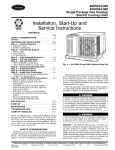
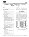
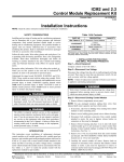
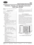
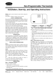
Integrated Control Motor (ICM2)
Troubleshooting Guide
CONTENTS
COMPONENT DESCRIPTION
GENERAL . . . . . . . . . . . . . . . . . . . . . . . . . . . . . . . . . . . 1
COMPONENT DESCRIPTION . . . . . . . . . . . . . . . . . 1-5
ICM2 Selection Modes . . . . . . . . . . . . . . . . . . . . . . . . 1
SEQUENCE OF OPERATION . . . . . . . . . . . . . . . . . . 5
Continuous Fan Operation . . . . . . . . . . . . . . . . . . . . 5
Cooling Mode, 50HX,SX Units . . . . . . . . . . . . . . . . . 5
Cooling Mode, 48HX,SX Units . . . . . . . . . . . . . . . . . 5
Heating Mode, 48HX,SX Units . . . . . . . . . . . . . . . . . 5
Electric Heat Mode . . . . . . . . . . . . . . . . . . . . . . . . . . . 5
Heat Pump, Heating with Auxiliary Heat . . . . . . . 5
ICM2 Control Power . . . . . . . . . . . . . . . . . . . . . . . . . . 5
Low-Voltage Circuit Fusing . . . . . . . . . . . . . . . . . . . 5
Motor Power Connections . . . . . . . . . . . . . . . . . . . . 5
OPERATING PROBLEMS . . . . . . . . . . . . . . . . . . . . . 5-7
Fan Will Not Turn On From Thermostat . . . . . . . . 5
Fan Will Turn On,
But Electric Heat Stages Will Not . . . . . . . . . . . 7
Easy Select Board Fuse Keeps Blowing . . . . . . . 7
Motor Does Not Run . . . . . . . . . . . . . . . . . . . . . . . . . 7
Motor Shaft Does Not Rotate Smoothly . . . . . . . . 7
Motor Does Not Run Smoothly . . . . . . . . . . . . . . . . 7
Motor Does Not Stop Running . . . . . . . . . . . . . . . . 7
TROUBLESHOOTING SUMMARY . . . . . . . . . . . . 8-16
The ICM2 (Fig. 1) is powered with high voltage at all
times. It is pre-programmed and contains airflows for all modes
of operation.
The ICM2 reacts to changes in system static pressures to
maintain constant airflow. The blower delivers requested airflow up to about 0.7 in. of static pressure.
The ICM2 will not operate with high voltage alone; low
voltage must be applied to the control plug for the motor to
run. The ICM2 is first fed high voltage through the 5-pin
connector. As this occurs, the AC power is rectified to DC
by a diode module. After rectification, the DC signal is electronically communicated and fed in sequential order to three
stator windings. The frequency of communication pulses determines motor speed. The rotor is permanently magnetized.
The ICM2 interfaces with the Easy Select Board (Fig. 2
and 3). Setting up desired system airflow is accomplished
through selections made on the Easy Select Board. Power
for the system is supplied from a 230-vac, 60 Hz line. A
class 2 voltage (24 vac nominal) transformer is used for thermostat connections. The transformer is located either in, or
below, the main unit control box, depending on the unit. The
secondary (SEC) side of the transformer is connected to the
control box. The 24-vac secondary circuit includes a socket,
soldered into the circuit at SEC2, to receive a 5-amp automotivetype fuse.
GENERAL
This manual contains information to assist in troubleshooting operating problems and errors associated with the
Integrated Control Motor (ICM2). The ICM2 is used in the
units listed in Table 1:
Table 1 — Units With ICM2
UNIT
48HX
48SX
50HX
50SX
UNIT SIZE
048,060
048,060
048,060
048,060
ICM2 Selection Modes — Connections to the thermostat are made at leads connected through P1 of the Easy
Select Board. Eighteen 0.187-in. quick-connect terminals comprise the field select taps, which provide programming selection for ICM2. Wiring for the 5 selection modes is listed
in Table 2.
Table 2 — ICM2 Selection Mode Wiring
MODE
AUX Heat Range
AC/HP Size
Type
AC/HP CFM Adjust
AC/HP Time Delay
WIRE COLOR
Violet
Blue
Orange
Black
Gray
LEGEND
Before performing service or repair operations on unit,
turn off main unit power. Electrical shock could cause
personal injury.
AC — Air Conditioning
HP — Heat Pump
Manufacturer reserves the right to discontinue, or change at any time, specifications or designs without notice and without incurring obligations.
Book 1 1 1 4 4 4
PC 111
Catalog No. 534-897
Printed in U.S.A.
Form 48/50HX,SX-1T
Pg 1
2-97
Replaces: New
Tab 1a 1b 5a 5a 6a 6b
Table 3 — Allowable Airflows for AUX HEAT
1
2
3
4
5
AUX
HEAT
POWER CONNECTOR
CFM
Gas Heat
Input Size
(Btuh)
80,000
100,000
120,000
140,000
Electric
Heater Package
(5-10 kW)
9 10 11 12 13 14 15 16
1 2 3 4 5 6 7 8
CONTROL CONNECTOR
DO NOT REMOVE
OPTIONAL
SAFETY
GROUND
EASY SELECT BOARD TERMINAL
1
2
3
4
1300
1400
1600
1700
X
X
X
X
X
X
X
X
X
X
X
X
X
X
AC/HP SIZE — the preset factory default selection forAC/HP
Size is 400 cfm per ton. The selection pins are configured
for 350 cfm per ton at terminals 1 and 3, and 400 cfm per
ton at terminals 2 and 4.
TYPE — The type is a preset factory default selection. The
factory setting is AC for 48/50SX units. For 48HX units, the
factory setting is AC. For 50HX units, the factory setting is
HP. The HPC provides the same airflow as the AC selection.
(See Fig. 2.)
OPTIONAL
SAFETY
GROUND
CONTROL
CONNECTOR
POWER
CONNECTOR
DRAIN
HOLE
Fig. 1 — Integrated Control Motor 2
The 48HX,SX and 50HX,SX units are factory-set to operate properly with system components. See Fig. 4 for factory default settings. To reconfigure a basic system, refer to
information printed on the circuit board next to select pins,
and to base unit installation instructions. Move the 5 selection wires to match the components used.
AUX HEAT RANGE — Airflow for 48HX,SX units is a
preset factory selection. The airflow selection must not be
set lower than the default. Refer to Table 3 for the allowable
airflows.
Airflow for 50HX,SX units requires the installer to
select the auxiliary heat airflow that best suits the installation. Refer to installation instructions for electric heaters. See
Table 3 for available airflow.
Each select pin is configured for a certain airflow. The airflow will be supplied in the emergency heat mode, which is
the heating mode on units with electric heat as the primary
heating source.
For heat pump units, the ICM2 will run whichever is higher;
heat pump airflow or electric heat airflow. The preset factory
default selection is the highest airflow. This helps ensure safe
heater operation.
LEGEND
IFO — Indoor (Evaporator) Fan On
JW — Jumper Wire
Fig. 2 — Easy Select Board
AC/HP CFM ADJUST — The preset factory default selection is MED. Selections HI and LO will adjust the airflow
supplied for all operation modes. Refer to Table 4. The selection options are provided for the installer to meet individual installation needs (static compensation, noise, etc.).
Table 4 — Airflow Percentage Difference From
Nominal (MED Setting)
MODE
FAN ONLY COOLING HEATING HEAT PUMP
LO ADJUST
−15%
−12.5%
−15%
−10%
HI ADJUST
15%
12.5%
15%
10%
2
3
P1
Y1
Y/Y2
R
G
E/W1/W2
JW1
W3
W2
E/W1
G
Y1
Y/Y2
O
C
R
L
LEGEND
IFO — Indoor Fan On
JW — Jumper Wire
7
6
5
4
3
2
1
P2
10
9
8
7
6
5
4
3
2
1
L
IFO
JW2
SEC 2
JW3
SEC 1
R2
2W
D3
D1
D2
O
R3
2W
Y/Y2
D5
D4
G
GRY
HI
HP
HPC
MED
3
4
AC
ORN
BLK
LO
TYPE
AC/HP
CFM ADJUST
2
1
AC/HP
TIME DELAY
Y1
Fig. 3 — Easy Select Board Circuitry
R1
2W
W2
4
3
3
4
2
2
1
VIO
BLU
1
AUX HEAT
RANGE
AC/HP
SIZE
48HX, SX MODELS
AUX. HEAT RANGE
1
VIO
2
1300
3
1400
4
1600
1750
AC/HP SIZE
1
BLU
2
1400
3
1600
4
1750
2000
TYPE
ORN
AC
BLK
LO
HPC
HP
AC/HP CFM ADJUST
MED
HI
AC/HP TIME DELAY
1
GRY
3
2
30 sec ON/
60 sec OFF
4
0 sec ON/
30 sec OFF
0 sec ON/
0 sec OFF
0 sec ON/
45 sec OFF
50SX MODELS
AUX. HEAT RANGE
1
VIO
2
1300
3
4
1600
1400
1750
AC/HP SIZE
1
BLU
2
1400
3
4
1750
1600
2000
TYPE
ORN
AC
BLK
LO
HPC
HP
AC/HP CFM ADJUST
MED
HI
AC/HP TIME DELAY
1
GRY
3
2
30 sec ON/
60 sec OFF
4
0 sec ON/
30 sec OFF
0 sec ON/
0 sec OFF
0 sec ON/
45 sec OFF
50HX MODELS
AUX. HEAT RANGE
1
VIO
2
1300
3
4
1600
1400
1750
AC/HP SIZE
1
BLU
2
1400
3
4
1750
1600
2000
TYPE
ORN
AC
BLK
LO
HPC
HP
AC/HP CFM ADJUST
MED
HI
AC/HP TIME DELAY
1
GRY
30 sec ON/
60 sec OFF
3
2
0 sec ON/
30 sec OFF
0 sec ON/
0 sec OFF
FACTORY DEFAULT SETTING
NOTE: The AC/HP Size setting is Terminal 2 for size 048 and Terminal 4 for size 060.
Fig. 4 — Factory Default Settings
4
4
0 sec ON/
45 sec OFF
AC/HP TIME DELAY — Four motor operation delay profiles are provided to customize and enhance system operation. These selections include an option for no delays, which
may be used during service procedures. When other components, such as Integrated Gas Control (IGC), are used to
perform the delay function the preset factory default setting
is terminal 2 for 48HX,SX units.
Also available is a 30-second ON/60-second OFF delay
profile at terminal 1. This profile may be used to allow system coils time to heat or cool, and may minimize some cold
blow in heat pump operation.
A 30-second OFF delay at terminal 3 and a 45-second OFF
delay at terminal 4 are optional.
Heat Pump, Heating With Auxiliary Heat — Thermostat closes circuits R to Y/Y2 and R to Y1, with R to W2,
W3 or E (and R to O in case of defrost). In the event that
electric heating is called for by the thermostat while heat
pump is operating in heat or defrost mode, the electric heating signal will appear at motor connector pin 1. If necessary,
the motor will modify airflow output to provide an airflow
that is safe for operation of electric heater.
ICM2 Control Power — The ICM2 control power is
supplied for R circuit through runs to motor control connector pin 5, then through motor control harness to motor. The
C side of low voltage control power circuit is connected by
printed circuit runs to motor connector pins 3 and 4, then
through motor control harness to motor.
SEQUENCE OF OPERATION
Low-Voltage Circuit Fusing — Low-voltage circuit
is fused by a board-mounted 5-amp automotive-type fuse placed
in series with transformer SEC2 and R circuit. The C circuit
of transformer is referenced to chassis ground through a printedcircuit run at SEC1, connected to a metal standoff marked
‘Ground Screw Required.’ A ground screw must be in place
or erratic motor operation may result.
Continuous Fan Operation — The thermostat closes
circuit R to G. The G signal is sent directly to ICM2.
Cooling Mode, 50HX and 50SX Units — The thermostat closes circuit R to G, R to Y/Y2, R to O, and R to Y1
(heat pump only) for single speed. The Y/Y2 signal is sent
directly to ICM2. On heat pump units, Y1 signal is also sent
directly to ICM2.
Motor Power Connections — The high-voltage
230-vac power input to the Easy Select Board is provided
through line side of contactor to plug 4 of motor. High voltage terminals are 4 and 5. Terminal 3 is ground connection.
Cooling Mode, 48HX and 48SX Units — Thermostat closes, closing circuits from R to G, R to Y1, R to Y2
and O (48HX units only). All but the G signal are sent to
ICM2 directly. The G signal is not sent directly because the
JW3 jumper is cut to prevent feedback in heating mode. The
G signal is sent to the Integrated Gas Control (IGC) board,
where the indoor fan contacts closes and energize the IFO
(Indoor Fan On) terminal. It is then sent to the ICM2
directly.
OPERATING PROBLEMS
Turn off all power to unit before performing any service
procedure to avoid the possibility of electric shock and
personal injury.
Heating Mode, 48HX and 48SX Units
48HX UNITS — For heat pumps, the thermostat closes, closing circuits R to G, R to Y1 and R to Y/Y2 are sent to ICM2
directly. The IGC board sends the G signal to ICM2 through
the IFO terminal.
For gas heat units, refer to sequence of operation, heating
mode for 48SX units, below.
48SX UNITS — Thermostat closes, closing circuit from R
to W1. Signal is sent to both the IGC board and the ICM2.
When the indoor fan contacts close on the IGC board, a
24-volt signal is sent to ICM2 through the IFO terminal.
Fan Will Not Turn On From Thermostat — This
may indicate a problem with high voltage connections. Perform the following checks:
1. Check power leads L1 and L2. If L1 and L2 are not receiving power the system cannot function.
2. Check 5-pin connector at motor for 230 volts, or check
for continuity.
3. Check the low-voltage transformer leads. Be sure they
are wired correctly.
4. Check output voltage of transformer secondary side SEC1
and SEC2. Ensure transformer output is approximately
24 vac. If transformer output is 0 vac and the transformer
is receiving correct input voltage (208 v or 240 v), then
the transformer must be replaced. Use a Carrierrecommended transformer.
Electric Heat Mode — Thermostat closes circuit R to
W2, W3, or E. The terminal block positions W2, W3 and E
are tied together by jumpers JW1 and JW2. These jumpers
are provided for future flexibility staging of electric heater
banks. When staging is a requirement, the installer must cut
jumpers and wires in thermostats, following common procedure and practice. The 3 electric heater inputs are also interlocked through diodes D1, D2 and D3 to motor input W.
5
If the transformer output is 24 vac, check the Easy Select
Board voltage as follows:
Check low-voltage fuse (Fig. 2). If fuse is blown, replace
it. The transformer cannot supply power to the Easy Select
Board with a loose or blown fuse.
If the fuse blows when the unit has power supplied to it,
the system likely has one of the following problems:
• Electrical short or miswiring. Check control circuit.
• Transformer load exceeding maximum of 40 va. If the load
is excessive, the low-voltage 5-amp fuse will blow to protect the transformer. Check relays for excessive current draw.
Refer to Tables 5 and 6 for male/female quick connect
terminals and connections.
Table 5 — Male/Female Quick Connect Terminals
FEMALE CONNECTION SIZE
MALE CONNECTION
Y/Y2
Y1
SEC1
0.25 x 0.032
SEC2
IFO
O
AUX1
AUX2
G
RED
0.187 x 0.032
L
UNITS 48/50HX,SX
High and single speed
Low speed compressor
Secondary connection from transformer (24 vac). This connection is
common to chassis ground through eyelet marked GROUND SCREW
REQUIRED.
Secondary connection from transformer (24 vac)
Indoor Fan ON terminal
4-Way valve
Low voltage ground for auxiliary option (24 vac)
Low voltage output for auxiliary option (24 vac)
Indoor Fan
Common to R screw terminal and SEC2
This connection is a field termination for use in connection leads (L) of
thermostat. There is no connection of this terminal with control circuitry.
Table 6 — Connections and Connector
TYPE
CONNECTION
TYPE
CONNECTOR
PIN NO.
Pin 1
Thermostat
Connection
10-Pin
Header
Integrated
Control Motor 2
7-Pin
Header
Pin
Pin
Pin
Pin
Pin
Pin
Pin
Pin
Pin
Pin
Pin
Pin
Pin
Pin
Pin
Pin
2
3
4
5
6
7
8
9
10
1
2
3
4
5
6
7
DESCRIPTION
L — This connection is a field termination for use in connecting leads (L) of
thermostat. There is no connection of this terminal with control circuitry.
R — Connection for R signal to thermostat (24 vac)
C — Connection for C terminal to thermostat (24 vac common)
O — Connection for O signal from thermostat
Y/Y2 — Connection for Y signal from thermostat
Y1 — Connection for low-speed compressor operation
G — Connection for G signal from thermostat
E/W1 — Connection for E signal from thermostat/W1 on Gas Heat
W2 — Connection for W2 signal from thermostat
W3 — Connection for W3 signal from outdoor thermostat
Diode OR output of E/W1 or W3 or W2 thermostat signals
Thermostat G signal
Common to C, SEC1, and chassis ground
Common to C, SEC1, and chassis ground
Common to R and SEC2 (via 5-amp fuse)
Thermostat Y/Y2 signal
Thermostat Y1 signal
6
2. Verify that there are approximately 230 v at terminals of
contactor. If not, determine if high-voltage is entering the
unit.
3. Verify that there is a low-voltage control signal to the motor. The motor receives control signals through the 7-pin
motor plug P2. The voltage output of each pin in the
plug will be different, depending on mode or operation.
Table 7 lists voltage present in each pin of 7-pin plug for
each operating mode. Testing should be done between the
points listed in Table 7, and the common C screw terminal. If all the values of any one of the operating modes
check out, and the motor still fails to run, it is likely the
motor is defective and will need replacement.
Fan Will Turn On, But Electric Heat Stages Will
Not — Perform the following checks:
1. Check relay wirings, fuses to electric heaters (if applicable), and voltage to relay. All relays numbered one receive a 24-vac signal. If the correct voltage is being received, check if relay is closing. If the relay is not closing,
relay must be replaced.
2. Check for blown diodes. If diodes are blown it is likely
that a plug is miswired. Easy Select Board must be replaced if diode is bad.
3. Check if traces on back of Easy Select Board are overheated. If traces are overheated, there likely has been a
high-voltage short, or high-voltage has been applied to a
low-voltage circuit. This can be prevented by ensuring
the Easy Select Board has been correctly wired prior to
applying power.
Motor Shaft Does Not Rotate Smoothly — The
motor shaft normally does not run smoothly. This is due to
steps in rotation, called motor cogging. The cogging is caused
by permanent magnets passing each pole in the motor.
However, the shaft should not require excessive force to
turn. If shaft is very difficult to turn, motor control or bearings have failed and the motor must be replaced.
Easy Select Board Fuse Keeps Blowing — When
the low-voltage fuse blows, it is likely that the transformer
would have blown had the low-voltage fuse not been in circuit to protect it. The fuse usually blows when there is high
current drawn on the transformer, high-voltage applied to the
low-voltage circuit, or a direct secondary short.
When there is high current drawn on the transformer, it is
most likely because the transformer has been shorted or the
system is drawing more va than the transformer rating allows. When fuse blows because of high voltage, the system
has mixed high and low voltage signals.
Perform the following checks:
1. Check transformer, thermostat and control box wiring.
2. Check to be sure low-voltage and high-voltage wiring are
connected to proper terminals.
3. Check va draw on transformer. If va draw is more than va
rating of the transformer, fuse will blow. Transformer must
be replaced with one that has a higher va rating.
Motor Does Not Run Smoothly — Perform the following check:
Check blower wheel for damage and determine if blower
wheel is out of balance. If it is not defective, the motor will
likely need replacement.
Motor Does Not Stop Running — Perform the following checks:
1. Check for good ground between motor ground lead, transformer common lead, and control board. If this does not
stop the motor, continue to Step 2.
2. Remove all thermostat wiring. If this makes the motor
stop, it means the circuit board is faulty and must be replaced. If it does not stop, continue to Step 3.
3. Remove the 7-pin plug. If motor still runs, replace motor.
Motor Does Not Run — Perform the following checks:
1. Check all plugs and receptacles on ICM2 circuit board
and motor for bad connections. Be sure all plugs are fully
seated.
Table 7 — Motor Control Test Values
SCREW TERMINALS
HAVING 24 VAC
OPERATING MODE
Electric
1-Speed AC
2-Speed AC, Low Speed
2-Speed AC, High Speed
1-Speed HP
1-Speed HP
2-Speed HP, Low Speed
2-Speed HP, Low Speed
2-Speed HP, High Speed
2-Speed HP, High Speed
Continous Fan
Heating
Cooling
Cooling
Cooling
Cooling
Heating
Cooling
Heating
Cooling
Heating
R
R
R
R
R
R
R
R
R
R
R
W2
Y/Y2
Y1
Y/Y2
Y/Y2
Y/Y2
Y1
Y1
Y/Y2
Y/Y2
G
W3*
G
G
G
G
G
G
G
Y1
Y1
E*
O
O
G
G
O
W
Pin 1
24 vac
0
0
0
0
0
0
0
0
0
0
VOLTAGES — 7-PIN PLUG
G
C
C
R
Pin2
Pin 3 Pin 4 Pin 5
0
0
0
24 vac
24 vac
0
0
24 vac
24 vac
0
0
24 vac
24 vac
0
0
24 vac
24 vac
0
0
24 vac
24 vac
0
0
24 vac
24 vac
0
0
24 vac
24 vac
0
0
24 vac
24 vac
0
0
24 vac
24 vac
0
0
24 vac
24 vac
0
0
24 vac
P2
Y/Y2
Pin 6
0
24 vac
0
24 vac
24 vac
24 vac
0
0
24 vac
24 vac
0
LEGEND
AC — Air Conditioning
HP — Heat Pump
*Pin 1 has 24 vac with or without jumpers whenever any individual heater input or any combination of heater inputs are energized.
7
Y
Pin 7
0
0
24 vac
0
0
0
24 vac
24 vac
24 vac
24 vac
0
TROUBLESHOOTING SUMMARY
Use Table 8 and Fig. 5-12 in troubleshooting.
Table 8 — Troubleshooting Summary
SYMPTOM
Motor runs in some operation modes,
but not in others.
CAUSE
Poor connection
between components
Burnt components
Circuit board will not operate.
Blown fuse
Blown transformer
Motor is hard to turn manually.
Motor control or bearing failure
Faulty circuit board, thermostat
Motor does not stop running.
Faulty motor
Motor does not operate.
Burnt components
REMEDY
Check wiring harness connectors (see Note 1).
Check for a good ground connection between
motor ground lead and circuit board screw.
Check thermostat connections (see Note 2).
Check for burn traces or burnt components. If present,
replace circuit board.
Check 5-amp fuse
Check for 24v between SEC1 and SEC2.
If no voltage present, check transformer.
Replace motor
Test circuit board by removing 7-pin plug from circuit board.
If motor stops, it is a problem with the circuit board or thermostat.
Test thermostat by disconnecting it from circuit board.
If motor fails to stop running once 7-pin plug is removed from
circuit board, replace motor.
Replace motor and verify that drip loop is present
on connection wires.
LEGEND
SEC — Secondary
NOTES:
1. To check wiring harness, shut off power to unit. Remove 5-pin plug from motor. See Fig. 1. Never remove 5-pin plug from motor with power on.
Check for 24v between pin-1 and pin-12 on the 16-pin plug. If no voltage is present, replace wiring harness. If voltage is present, jumper terminals
R-Y/Y2 on circuit board and check for 24v between pin-12 and pin-14 and pin-16 (see below).
16
15
14
13
12
11
10
9
8
7
6
5
4
3
2
1
16-PIN PLUG
2. To check thermostat, remove thermostat wires from circuit board. Jumper screw terminals one at a time as follows: R-G, R-Y/Y2, R-Y1 and R-W2
to check connections.
8
LEGEND
AWG
BR
C
CAP
CB
COMP
CR
CTD
DB
DFT
DR
EQUIP
FL
FS
FU
GND
GVR
HLR
HR
HS
HV TRAN
I
ICM
IDM
IFM
IFO
IGC
LPS
LR
LS
MGV
OAT
OFM
QT
RS
RVS
SEC
TRAN
—
—
—
—
—
—
—
—
—
—
—
—
—
—
—
—
—
—
—
—
—
—
—
—
—
—
—
—
—
—
—
—
—
—
—
—
—
—
American Wire Gage
Blower Relay
Contactor, Compressor
Capacitor
Circuit Breaker
Compressor Motor
Compressor Relay
Compressor Time Delay
Defrost Board
Defrost Thermostat
Defrost Relay
Equipment
Fuse Link
Flame Sensor
Fuse
Ground
Gas Valve Relay
Heater Lockout Relay
Heater Relay (Strip Heat)
Hall Effect Sensor
High-Voltage Transformer
Ignitor
Integrated Control Motor
Induced-Draft Motor
Indoor-Fan Motor
Indoor-Fan On
Integrated Gas Control
Low-Pressure Switch
Lockout Relay
Limit Switch
Main Gas Valve
Outdoor-Air Thermostat
Outdoor-Fan Motor
Quadruple Terminal
Rollout Switch
Reversing Valve Solenoid
Secondary
Transformer
Field Splice
Marked Wire
Terminal (Marked)
Terminal (Unmarked)
Terminal Block
Splice
Splice (Marked)
Factory Wiring
Field Control Wiring
Field Power Wiring
Accessory or Optional Wiring
To Indicate Common Potential
Only, Not to Represent Wiring
NOTES:
1. If any of the original wire furnished must be
replaced, it must be replaced with type
90 C wire or its equivalent.
2. Set heat anticipator at .6.
3. Use copper conductors only.
4. ICM board connections.
TERMINAL
NO.
1
2
3
4
CFM
(VIO) Aux,
Heat Range
1300
1400
1600
1750
(BLU) AC/HP
Size
1400
1600
1750
2000
(GRY) AC/HP 30 sec. ON 0 sec. ON 0 sec. ON
0 sec. ON
Time Delay
1 min. OFF 0 sec. OFF 30 sec. OFF 45 sec. OFF
LED INDICATIONS
ERROR MODE
LED INDICATION
Normal Operation
ON
Hardware Failure
OFF
Fan ON/OFF Delay Modified 1 FLASH
Limit Switch Fault
2 FLASH
Flame Sense Fault
3 FLASH
5 Consecutive Limit Switch
Faults
4 FLASH
Ignition Lockout Fault
5 FLASH
Inducer Switch Fault
6 FLASH
Rollout Switch Fault
7 FLASH
Internal Control Fault
8 FLASH
1. Three-second pause between error
code display.
2. If more than one error exits, all applicable error codes shall be displayed in
numerical sequence.
Fig. 5 — Wiring Diagram, Units 48HX048,060; 208/230-1-60
9
LEGEND
AWG
BR
C
CAP
CB
COMP
CR
CTD
DB
DFT
DR
EQUIP
FL
FS
FU
GND
GVR
HLR
HR
HS
HV TRAN
I
ICM
IDM
IFM
IFO
IGC
IP
LPS
LR
LS
MGV
OAT
OFM
QT
RS
RVS
SEC
TH
TRAN
—
—
—
—
—
—
—
—
—
—
—
—
—
—
—
—
—
—
—
—
—
—
—
—
—
—
—
—
—
—
—
—
—
—
—
—
—
—
—
—
American Wire Gage
Blower Relay
Contactor, Compressor
Capacitor
Circuit Breaker
Compressor Motor
Compressor Relay
Compressor Time Delay
Defrost Board
Defrost Thermostat
Defrost Relay
Equipment
Fuse Link
Flame Sensor
Fuse
Ground
Gas Valve Relay
Heater Lockout Relay
Heater Relay (Strip Heat)
Hall Effect Sensor
High-Voltage Transformer
Ignitor
Integrated Control Motor
Induced-Draft Motor
Indoor-Fan Motor
Indoor-Fan On
Integrated Gas Control
Internal Protector
Low-Pressure Switch
Lockout Relay
Limit Switch
Main Gas Valve
Outdoor-Air Thermostat
Outdoor-Fan Motor
Quadruple Terminal
Rollout Switch
Reversing Valve Solenoid
Secondary
Thermostat-Heating
Transformer
Field Splice
Marked Wire
Terminal (Marked)
Terminal (Unmarked)
Terminal Block
Splice
Splice (Marked)
Factory Wiring
Field Control Wiring
Field Power Wiring
Accessory or Optional Wiring
To Indicate Common Potential
Only, Not to Represent Wiring
NOTES:
1. If any of the original wire furnished must be
replaced, it must be replaced with type
90 C wire or its equivalent.
2. Set heat anticipator at .6.
3. Use copper conductors only.
4. ICM board connections.
TERMINAL
NO.
1
2
3
4
CFM
(VIO) Aux,
Heat Range
1300
1400
1600
1750
(BLU) AC/HP
Size
1400
1600
1750
2000
(GRY) AC/HP
Time Delay
30 sec.
ON
1 min.
OFF
0 sec.
ON
0 sec.
OFF
0 sec.
ON
30 sec.
OFF
0 sec.
ON
45 sec.
OFF
LED INDICATIONS
ERROR MODE
LED INDICATION
Normal Operation
ON
Hardware Failure
OFF
Fan ON/OFF Delay Modified 1 FLASH
Limit Switch Fault
2 FLASH
Flame Sense Fault
3 FLASH
5 Consecutive Limit Switch
Faults
4 FLASH
Ignition Lockout Fault
5 FLASH
Inducer Switch Fault
6 FLASH
Rollout Switch Fault
7 FLASH
Internal Control Fault
8 FLASH
1. Three-second pause between error
code display.
2. If more than one error exits, all applicable error codes shall be displayed in
numerical sequence.
Fig. 6 — Wiring Diagram, Units 48HX048,060; 208/230-3-60
10
LEGEND
AWG
BR
C
CAP
COMP
CR
EQUIP
FL
FS
FU
GND
GVR
HS
HV TRAN
I
ICM
IDM
IFM
IGC
LS
MGV
NEC
OFM
PWR
QT
—
—
—
—
—
—
—
—
—
—
—
—
—
—
—
—
—
—
—
—
—
—
—
—
—
American Wire Gage
RS
Blower Relay
SEC
Contactor
TRAN
Capacitor
Compressor Motor
Combustion Relay
Equipment
Fuse Link
Flame Sensor
Fuse
Ground
Gas Valve Relay
Hall Effect Sensor
High-Voltage Transformer
Ignitor
Integrated Control Motor
Induced-Draft Motor
Indoor-Fan Motor
Integrated Gas Control
Limit Switch
Main Gas Valve
National Electrical Code
Outdoor-Fan Motor
Power
Quadruple Terminal
—
—
—
Rollout Switch
Secondary
Transformer
Field Splice
Terminal (Marked)
NOTES:
1. If any of the original wire furnished must be replaced, it
must be replaced with type 90 C wire or its equivalent.
2. Use copper conductors only.
3. ICM board connections.
TERMINAL
NO.
2
Splice
Splice (Marked)
Factory Wiring
Field Control Wiring
Field Power Wiring
Accessory or
Optional Wiring
To Indicate
Common Potential
Only, Not to
Represent Wiring
3
4
CFM
(VIO) Aux,
Heat Range
(BLU) AC/HP
Size
(GRY) AC/HP
Time Delay
Fig. 7 — Wiring Diagram, Units 48SX048,060; 208/230-1-60
11
1
Terminal (Unmarked)
1300
1400
1600
1750
1400
1600
1750
2000
30 sec.
ON
1 min.
OFF
0 sec.
ON
0 sec.
OFF
0 sec.
ON
30 sec.
OFF
0 sec.
ON
45 sec.
OFF
LEGEND
AWG
BR
C
CAP
COMP
CR
EQUIP
FL
FS
FU
GND
GVR
HS
HV TRAN
I
ICM
IDM
IFM
IGC
LS
MGV
NEC
OFM
PWR
QT
—
—
—
—
—
—
—
—
—
—
—
—
—
—
—
—
—
—
—
—
—
—
—
—
—
American Wire Gage
Blower Relay
Contactor
Capacitor
Compressor Motor
Combustion Relay
Equipment
Fuse Link
Flame Sensor
Fuse
Ground
Gas Valve Relay
Hall Effect Sensor
High-Voltage Transformer
Ignitor
Integrated Control Motor
Induced-Draft Motor
Indoor-Fan Motor
Integrated Gas Control
Limit Switch
Main Gas Valve
National Electrical Code
Outdoor-Fan Motor
Power
Quadruple Terminal
RS
RT
SEC
TRAN
—
—
—
—
Rollout Switch
Red Terminal
Secondary
Transformer
Field Splice
Terminal (Marked)
NOTES:
1. If any of the original wire furnished must be replaced, it
must be replaced with type 90 C wire or its equivalent.
2. Use copper conductors only.
3. ICM board connections.
TERMINAL
NO.
2
Splice
Splice (Marked)
Factory Wiring
Field Control Wiring
Field Power Wiring
Accessory or
Optional Wiring
To Indicate
Common Potential
Only, Not to
Represent Wiring
3
4
CFM
(VIO) Aux,
Heat Range
(BLU) AC/HP
Size
(GRY) AC/HP
Time Delay
Fig. 8 — Wiring Diagram, Units 48SX048,060; 208/230-3-60
12
1
Terminal (Unmarked)
1300
1400
1600
1750
1400
1600
1750
2000
30 sec.
ON
1 min.
OFF
0 sec.
ON
0 sec.
OFF
0 sec.
ON
30 sec.
OFF
0 sec.
ON
45 sec.
OFF
AWG
C
CAP
COMP
CTD
DB
DFT
DR
EQUIP
FL
FU
GND
HR
ICM
IFM
IFO
IP
LPS
OF
OFM
QT
RVS
SEC
TRAN
—
—
—
—
—
—
—
—
—
—
—
—
—
—
—
—
—
—
—
—
—
—
—
—
LEGEND
American Wire Gage
Contactor, Compressor
Capacitor
Compressor Motor
Compressor Time Delay
Defrost Board
Defrost Thermostat
Defrost Relay
Equipment
Fuse Link
Fuse
Ground
Heater Relay (Strip Heat)
Integrated Control Motor
Indoor-Fan Motor
Indoor-Fan On
Internal Protector
Low-Pressure Switch
Outdoor Fan
Outdoor-Fan Motor
Quadruple Terminal
Reversing Valve Solenoid
Secondary
Transformer
TERMINAL NO.
NOTES:
1. If any of the original wire furnished
must be replaced, it must be replaced with type 90 C wire or its
equivalent.
2. Set heat anticipator at .6.
3. Use copper conductors only.
4. ICM board connections.
1
Marked Wire
Terminal (Marked)
Terminal (Unmarked)
Terminal Block
Splice
Splice (Marked)
Factory Wiring
Field Control Wiring
Field Power Wiring
Accessory or
Optional Wiring
To Indicate
Common Potential
Only, Not to
Represent Wiring
2
3
4
1600
1750
1750
2000
CFM
(VIO) Aux, Heat Range
(BLU) AC/HP Size
1300
1400
1400
1600
sec. ON 0 sec. ON 0 sec. ON
0 sec. ON
(GRY) AC/HP Time Delay 30
1 min. OFF 0 sec. OFF 30 sec. OFF 45 sec. OFF
Fig. 9 — Wiring Diagram, Units 50HX048,060; 208/230-1-60
13
Field Splice
LEGEND
AWG
C
CAP
COMP
CTD
DB
DFT
DR
EQUIP
FL
FU
GND
HR
ICM
IFM
IFO
IP
LPS
LS
OFM
QT
RVS
TRAN
—
—
—
—
—
—
—
—
—
—
—
—
—
—
—
—
—
—
—
—
—
—
—
American Wire Gage
Contactor, Compressor
Capacitor
Compressor Motor
Compressor Time Delay
Defrost Board
Defrost Thermostat
Defrost Relay
Equipment
Fuse Link
Fuse
Ground
Heater Relay (Strip Heat)
Integrated Control Motor
Indoor-Fan Motor
Indoor-Fan On
Internal Protector
Low-Pressure Switch
Limit Switch
Outdoor-Fan Motor
Quadruple Terminal
Reversing Valve Solenoid
Transformer
TERMINAL NO.
1
Field Splice
Marked Wire
Terminal (Marked)
Terminal (Unmarked)
Terminal Block
Splice
Splice (Marked)
Factory Wiring
Field Control Wiring
Field Power Wiring
Accessory or
Optional Wiring
To Indicate
Common Potential
Only, Not to
Represent Wiring
2
3
4
1600
1750
1750
2000
CFM
NOTES:
1. If any of the original wire furnished must be replaced, it
must be replaced with type 90 C wire or its equivalent.
2. Set heat anticipator at .6.
3. Use copper conductors only.
4. ICM board connections.
(VIO) Aux, Heat Range
(BLU) AC/HP Size
1300
1400
sec. ON 0 sec. ON
0 sec. ON
0 sec. ON
(GRY) AC/HP Time Delay 30
1 min. OFF 0 sec. OFF 30 sec. OFF 45 sec. OFF
Fig. 10 — Wiring Diagram, Units 50HX048,060; 208/230-3-60
14
1400
1600
AWG
C
CAP
COMP
EQUIP
FL
FU
GND
HR
ICM
IFO
OFM
QT
SEC
TRAN
—
—
—
—
—
—
—
—
—
—
—
—
—
—
—
LEGEND
American Wire Gage
Contactor, Compressor
Capacitor
Compressor Motor
Equipment
Fuse Link
Fuse
Ground
Heater Relay (Strip Heat)
Integrated Control Motor
Indoor-Fan On
Outdoor-Fan Motor
Quadruple Terminal
Secondary
Transformer
Terminal (Marked)
Terminal (Unmarked)
Terminal Block
Splice
Splice (Marked)
Factory Wiring
Field Control Wiring
Field Power Wiring
Accessory or
Optional Wiring
To Indicate
Common Potential
Only, Not to
Represent Wiring
Field Splice
Marked Wire
NOTES:
1. If any of the original wire furnished must be replaced, it must be replaced with type
90 C wire or its equivalent.
2. Number(s) indicates the line location of contacts. A bracket over (2) numbers signifies
single pole double throw contacts. An underlined number signify a normally closed contact. Plain numbers (no lines), signify a normally open contact.
3. Set heat anticipator at .6 amp for first stage and .3 amp for second stage.
4. Use copper conductors only.
5. ICM board connections.
TERMINAL NO.
1
2
3
4
CFM
(VIO) Aux,
Heat Range
(BLU)
AC/HP Size
(GRY) AC/HP
Time Delay
1300
1400
1600
1750
1400
1600
1750
2000
30 sec. ON 0 sec. ON 0 sec. ON
0 sec. ON
1 min. OFF 0 sec. OFF 30 sec. OFF 45 sec. OFF
Fig. 11 — Wiring Diagram, Units 50SX048,060; 208/230-1-60
15
LEGEND
AWG
C
CAP
COMP
EQUIP
FL
FU
GND
HR
ICM
IFM
IFO
OFM
QT
SEC
TRAN
—
—
—
—
—
—
—
—
—
—
—
—
—
—
—
—
American Wire Gage
Contactor, Compressor
Capacitor
Compressor Motor
Equipment
Fuse Link
Fuse
Ground
Heater Relay (Strip Heat)
Integrated Control Motor
Indoor-Fan Motor
Indoor-Fan On
Outdoor-Fan Motor
Quadruple Terminal
Secondary
Transformer
Marked Wire
Terminal (Marked)
Terminal (Unmarked)
Terminal Block
Splice
Splice (Marked)
Factory Wiring
Field Control Wiring
Field Power Wiring
Accessory or Optional Wiring
To Indicate Common Potential
Only, Not to Represent Wiring
Field Splice
NOTES:
1. If any of the original wire furnished must be replaced, it must be replaced with type 90 C wire
or its equivalent.
2. Number(s) indicates the line location of contacts. A bracket over (2) numbers signifies single
pole double throw contacts. An underlined number signifies a normally closed contact. Plain
numbers (no lines), signify a normally open contact.
3. Set heat anticipator at .6 amp for first stage and .3 amp for second stage.
4. Use copper conductors only.
5. ICM board connections.
TERMINAL
NO.
1
2
3
4
CFM
(VIO) Aux,
Heat Range
(BLU) AC/HP
Size
1300
1400
1600
1750
1400
1600
1750
2000
(GRY) AC/HP
Time Delay
30 sec. ON
1 min. OFF
0 sec. ON
0 sec. OFF
0 sec. ON
30 sec. OFF
0 sec. ON
45 sec. OFF
Fig. 12 — Wiring Diagram, Units 50SX048,060; 208/230-3-60
Copyright 1997 Carrier Corporation
Manufacturer reserves the right to discontinue, or change at any time, specifications or designs without notice and without incurring obligations.
Book 1 1 1 4 4 4
PC 111
Catalog No. 534-897
Printed in U.S.A.
Form 48/50HX,SX-1T
Pg 16
2-97
Replaces: New
Tab 1a 1b 5a 5a 6a 6b