1
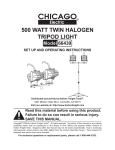
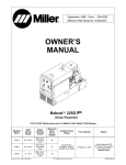
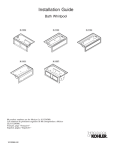
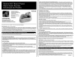
JETTED SINK INSTALLATION INSTRUCTIONS
Table of Contents
JETTED SINK SAFETY........................................................... 1
INSTALLATION REQUIREMENTS ........................................ 2
Tools and Parts .................................................................... 2
Location Requirements ........................................................ 2
Electrical Requirements ....................................................... 2
Plumbing Requirements....................................................... 3
INSTALLATION INSTRUCTIONS ......................................... 3
Unpack Jetted Sink.............................................................. 3
Prepare Countertop ...................................................................3
Prepare Jetted Sink ...................................................................3
Install Pop-Up Drain...................................................................4
Install Faucet..............................................................................5
Install Jetted Sink.......................................................................5
Connect Water Supply...............................................................5
Connect Power Supply..............................................................6
Complete Installation .................................................................6
®
JETTED SINK SAFETY
Your safety and the safety of others are very important.
We have provided many important safety messages in this manual and on your appliance. Always read and obey all safety
messages.
This is the safety alert symbol.
This symbol alerts you to potential hazards that can kill or hurt you and others.
All safety messages will follow the safety alert symbol and either the word “DANGER” or “WARNING.”
These words mean:
DANGER
WARNING
You can be killed or seriously injured if you don't immediately
follow instructions.
You can be killed or seriously injured if you don't follow
instructions.
All safety messages will tell you what the potential hazard is, tell you how to reduce the chance of injury, and tell you what can
happen if the instructions are not followed.
8537100B
INSTALLATION REQUIREMENTS
NOTE: The countertop on the right-hand side of the cabinet must
extend at least 6" (15.2 cm) from the right side of the opening to
the inside cabinet wall. This location will accommodate the
pump/motor, which must be enclosed.
Tools and Parts
Gather the required tools and parts before starting installation.
Read and follow the instructions provided with any tools listed
here.
Countertop cutout dimensions
Tools Needed
■
Jigsaw
■
Tub and tile caulk
■
Hole saw
■
Dust mask
■
Drill
36"
(91.4 cm)
23"
(58.4 cm)
20"
(50.8 cm)
Parts Needed
■
Faucet with check valve and accompanying plumbing
supplies as needed
Check local codes. Check existing electrical supply. See
“Electrical Requirements.”
All plumbing connections should be made by a licensed, qualified
plumber.
6"
(15.2 cm)
min.
24"
(61 cm)
A
Location Requirements
Proper installation is your responsibility.
You will need:
■ A water heater set to deliver a maximum of 120°F (49°C)
water to the jetted sink.
■
A. Radius corners—1" (2.5 cm)
Access to a hot and cold water supply and drain as shown.
Electrical Requirements
A
WARNING
B
C
Electrical Shock Hazard
Plug into a grounded 3 prong outlet.
A. Hot and cold water supply
B. Grounded 3 prong, GFCI-protected electrical outlet
C. Drain
Do not remove ground prong.
Do not use an adapter.
■
■
This outlet must be a grounded 3 prong, GFCI-protected
electrical outlet located inside the base cabinet. The GFCIprotected electrical outlet must be installed within 2 ft (61 cm)
of the countertop on the right side and a minimum of 16"
(40.6 cm) above the finished floor to allow room for the timer.
Do not use an extension cord.
Failure to follow these instructions can result in death,
fire, or electrical shock.
A 36" x 24" (91.4 cm x 61 cm) countertop with a 23" x 20"
(58.4 cm x 50.8 cm) opening with 1" (2.5 cm) radius corners
to install sink basin.
■
2
The jetted sink is supplied with a 1 HP, 110 volt pump/motor
that draws 6.5 amps. A 15 amp, grounded 3 prong,
GFCI-protected electrical outlet is required.
■
A circuit breaker is recommended.
■
■
The jetted sink is equipped with a power supply cord having a
3 prong grounding plug.
Check with a qualified electrician if you are not sure the jetted
sink is properly grounded.
■
Do not have a fuse in the neutral or ground circuit.
■
To minimize possible shock hazard, the timer must be
plugged into a mating, 3 prong, grounding-type outlet,
grounded in accordance with local codes and ordinances. If a
mating GFCI-protected electrical outlet is not available, it is
the personal responsibility and obligation of the customer to
have the properly grounded GFCI-protected electrical outlet
installed by a qualified electrician.
Plumbing Requirements
Sink should be plumbed to local plumbing codes.
All plumbing connections should be made by licensed, qualified
plumbers.
INSTALLATION INSTRUCTIONS
This jetted sink has been water tested and found to be fully
operational and leak free prior to shipping. Freight handling and
job site exposure might have caused the jetted sink's condition
to deteriorate. This unit must be tested for leaks and defects prior
to enclosure/final installation. Failure to test for leaks and defects
will void the warranty.
Style 2
If installing the faucet in the jetted sink, you must first drill a
faucet hole into the sink itself before installing the jetted sink in
the countertop opening. Use the appropriate size hole saw to
make an opening large enough for your faucet.
2. Working with 2 or more people, either on the floor or on the
countertop, whichever is more comfortable, place the jetted
sink upside down on top of the 2 longer crossbars that you
saved from the sink packaging as shown.
Unpack Jetted Sink
WARNING
Excessive Weight Hazard
Use two or more people to move and install jetted sink.
Failure to do so can result in back or other injury.
■
Remove jetted sink from shipping carton. Remove all
protective packaging materials such as tape and shipping
pads. Save the 2 longer crossbars that were used to brace
the sink in the carton. You will need these later.
■
To prevent floor damage, set the jetted sink onto cardboard
prior to installing in countertop.
A
Prepare Countertop
A. Crossbars from packing materials
1. Place the jetted sink upside down on the countertop in the
location where you want it installed.
2. With a pencil, trace a line around the outside edge of the
jetted sink onto the countertop. Remove the jetted sink from
the countertop.
3. Measure in ¹⁄₂" (1.3 cm) and draw a new line inside the first
jetted sink outline. Cut the countertop on this inside line.
3. Determine the location on the underside of the jetted sink
where you will install the faucet. Mark the correct placement
for the holes with a pencil.
IMPORTANT:
■
Care must be taken when drilling to avoid damaging the
jetted sink.
■
While drilling, do not apply excessive pressure. Allow the
drill to do the work.
■
Do not drill completely through the top surface.
Prepare Jetted Sink
1. Determine faucet location.
4. Drill a pilot hole from the bottom first. Stop drilling when the
pilot bit pierces the top surface of the jetted sink.
5. Flip the jetted sink over so that it is right side up. Place on
cardboard packing material.
6. Drilling from the top, place the pilot bit into the hole you made
while drilling from the back.
7. Drill straight down and through the jetted sink.
Style 1
If installing the faucet in the countertop, prepare the openings
needed now. You have the option of locating the faucet opening
in the countertop at either the rear or left-hand side of the sink.
3
Install Pop-Up Drain
4. Make sure the grating and the waste body are aligned and
seated to let the water pass freely.
5. Using the large, flat-head screw, attach the grating to the
waste body assembly. Do not fully tighten the screw.
A
I
J
K
B
L
C
A
M
D
E
F
G
N
H
A. Grating
A. Drain plug
B. Adjusting screw
C. Large flat-head screw
D. Grating
E. Sponge seal
F. Jetted sink base
G. Rubber seal
H. Waste body
I. Pop-up drain control
J. Top nut
K. Rubber seal
L. Locknut
M. Torque tube
N. Cable assembly
6. Attach the pop-up drain control knob to the torque tube.
Screw the locknut sufficiently down the torque tube to allow
the torque tube to be pushed up through the hole in the sink.
Fit the rubber seal onto the torque tube and push the torque
tube up through the hole.
1. Fit the white, sponge seal to the grating and place the grating
in the drain hole.
2. Fit the black, rubber seal (ribbed side up) into the recess in
the top of the waste body.
3. Place the waste body assembly on the underside of the jetted
sink directly below the grating.
7. Screw the top nut down the torque tube as far as it will go.
8. Push the torque tube back down the hole until the shoulder of
the top nut is touching the sink.
A
A. Waste body assembly
4
9. On the underside of the jetted sink, finger tighten the locknut.
Install Faucet
Install a faucet with a check valve in the countertop or the sink
according to the instructions provided with the faucet.
Install Jetted Sink
NOTE: Before installing the sink into the countertop, attach one
end of the clear, air-line hose to the bottom of the jetted sink on/
off button as shown.
10. Attach the pop-up drain control knob.
A
C
B
11. Swivel the waste body and the torque tube into the best
position to avoid contact with other jetted sink accessories,
making sure the control cable is not twisted.
12. Fully tighten the locknut. Push in the control knob and twist to
check that the movement functions freely.
13. Fully tighten the large, flat-head screw.
NOTE: Do not overtighten the large, flat-head screw. Hand
tight plus ¹⁄₄ turn should be sufficient to ensure an adequate
seal.
A. Clear, air-line hose
B. On/off button (bottom)
C. On/off button (top)
14. Adjust the drain plug height by turning the adjusting screw.
1. Caulk under the lip of the jetted sink and place it in the
23" x 20" (58.4 cm x 50.8 cm) hole cutout (no clamps or
screws required).
2. Clean the excess caulk off the countertop and let dry
completely before using.
Connect Water Supply
The jetted sink should be plumbed to local plumbing codes.
All plumbing connections should be made by licensed, qualified
plumbers.
A
A. Adjusting screw
5
Connect Power Supply
The TF-1TD is a solid state switch with a built-in, 10-minute time
delay feature. The unit plugs into any grounded 3 prong
GFCI-protected electrical wall outlet.
IMPORTANT: It is recommended that the timer control be
installed in-line between the 115V AC power supply and the
grounded 3 prong GFCI-protected electrical outlet. Consult an
electrician or other qualified installer for assistance.
WARNING
Electrical Shock Hazard
Plug into a grounded 3 prong outlet.
Do not remove ground prong.
Do not use an adapter.
Do not use an extension cord.
Failure to follow these instructions can result in death,
fire, or electrical shock.
1. Plug the cord into the receptacle on the TF-1TD timer control
box.
2. Plug the TF1TD timer control box into a grounded 3 prong
GFCI-protected electrical outlet.
3. Attach the other end of the clear, air-line hose to the bottom
of the TF-1TD timer control box. You may cut the hose to the
proper length if necessary.
Complete Installation
1. Check to be sure you have all of your tools.
2. Check the electrical requirements. Be sure that you have the
correct electrical supply and the recommended grounding
method. See “Electrical Requirements.”
3. Check to be sure all parts are now installed. If there is an
extra part, go back through the steps to see which step was
skipped.
4. Dispose of/recycle all packaging materials.
5. Check to be sure the water faucets are working.
6. Check for leaks around the faucet and drain.
7. Use a mild solution of liquid household cleaner and warm
water to remove waxy residue caused by the protective
shipping material. Dry thoroughly with a soft cloth. For more
information, see the “Cleaning Your Jetted Sink” section of
the Use and Care Guide.
8. Read “Jetted Sink Use” in the Jetted Sink Use and Care
Guide.
9. To test your jetted sink, fill it to the correct level with water
and measure half of the normal recommended amount of
low-sudsing detergent. Pour detergent into the jetted sink.
Set the jet speed control and push the on/off button to start
the pump/motor. Allow it to complete one 10-minute cycle.
E
4³⁄₈" (11.1 cm)
F
A
B
1³⁄₄" (4.5 cm)
3¹⁄₈" (7.9 cm)
C
D
A. Grounded 3 prong GFCI-protected
electrical outlet
B. TF-1TD unit
C. Clear air-line hose
D. Pump/motor
E. On/off button
F. Jetted sink basin
8537100B
© 2004 Whirlpool Corporation.
All rights reserved.
® Registered Trademark/TM Trademark of Whirlpool, U.S.A.
11/04
Printed in U.S.A.